Embed Size (px)
Citation preview

HAL Id: hal-00848875https://hal.archives-ouvertes.fr/hal-00848875
Submitted on 29 Jul 2013
HAL is a multi-disciplinary open accessarchive for the deposit and dissemination of sci-entific research documents, whether they are pub-lished or not. The documents may come fromteaching and research institutions in France orabroad, or from public or private research centers.
L’archive ouverte pluridisciplinaire HAL, estdestinée au dépôt et à la diffusion de documentsscientifiques de niveau recherche, publiés ou non,émanant des établissements d’enseignement et derecherche français ou étrangers, des laboratoirespublics ou privés.
A comprehensive detailed chemical kinetic reactionmechanism for combustion of n-alkane hydrocarbons
from n-octane to n-hexadecaneCharles K. Westbrook, William J. Pitz, Olivier Herbinet, Henry J. Curran,
Emma J. Silke
To cite this version:Charles K. Westbrook, William J. Pitz, Olivier Herbinet, Henry J. Curran, Emma J. Silke. Acomprehensive detailed chemical kinetic reaction mechanism for combustion of n-alkane hydrocar-bons from n-octane to n-hexadecane. Combustion and Flame, Elsevier, 2008, 156, pp.181-199.�10.1016/j.combustflame.2008.07.014�. �hal-00848875�

A comprehensive detailed chemical kinetic reaction mechanism for combustion of n‐alkane hydrocarbons from n‐octane to n‐hexadecane
Charles K. Westbrooka,*, William J. Pitza, Olivier Herbineta, Henry J. Currana,b, Emma J. Silkea
aLawrence Livermore National Laboratory, Livermore, CA 94550, USA bUniversity College of Ireland, Galway, Ireland
Abstract Detailed chemical kinetic reaction mechanisms have been developed to describe the pyrolysis and oxidation of nine n‐alkanes larger than n‐heptane, including n‐octane (n‐C8H18), n‐nonane (n‐C9H20), n‐decane (n‐C10H22), n‐undecane (n‐C11H24), n‐dodecane (n‐C12H26), n‐tridecane (n‐C13H28), n‐tetradecane (n‐C14H30), n‐pentadecane (n‐C15H32), and n‐hexadecane (n‐C16H34). These mechanisms include both high temperature and low temperature reaction pathways. The mechanisms are based on previous mechanisms for the primary reference fuels n‐heptane and iso‐octane, using the reaction classes first developed for n‐heptane. Individual reaction class rules are as simple as possible in order to focus on the parallelism between all of the n‐alkane fuels included in the mechanisms. These mechanisms are validated through extensive comparisons between computed and experimental data from a wide variety of different sources. In addition, numerical experiments are carried out to examine features of n‐alkane combustion in which the detailed mechanisms can be used to compare reactivities of different n‐alkane fuels. The mechanisms for these n‐alkanes are presented as a single detailed mechanism, which can be edited to produce efficient mechanisms for any of the n‐alkanes included, and the entire mechanism, with supporting thermochemical and transport data, together with an explanatory glossary explaining notations and structural details, is available for download from our web page. Keywords: Kinetic modeling; Hydrocarbons; Ignition

1. Introduction Practical fuels for transportation and other systems consist of complex mixtures of many types of hydrocarbon species. Jet fuels, diesel fuel, gasoline and natural gas contain hundreds and often thousands of distinct chemical compounds. To deal with this complexity, species can be collected into structural classes in order to understand their combustion properties and construct surrogate mixtures for those practical fuels. It is common to define surrogates for practical fuels in terms of several basic structural classes of compounds, usually n‐alkanes, branched or iso‐alkanes, aromatics, polycyclic alkanes, olefins, naphthenes, and oxygenated hydrocarbons for gasoline [1], diesel fuel [2], and jet fuel [3,4]. Straight‐chain or n‐alkane species are important components in all of these practical transportation fuels. The structure of a hydrocarbon fuel has a profound impact on the ignition and other combustion properties of that fuel. Empirical correlations between species molecular size and structure and ignition properties have existed for many years [5], based on experimental studies, and in recent years, the roles of fundamental kinetic properties of these hydrocarbon fuels on ignition rates have become clearer [6‐8]. Straight‐chain hydrocarbons are more easily ignited under engine conditions than branched‐chain or aromatic hydrocarbons, and these ignition properties are commonly quantified in terms of octane number for spark‐ignition engines and cetane number for diesel engines. Ignition properties are also of central importance in homogeneous charge, compression ignition (HCCI) engines and other configurations of similar behavior that involve low temperature combustion (LTC). The familiar octane and cetane scales are both defined in terms of reference fuels which provide practical limits to ignition properties. For both scales, there is a reference fuel that ignites easily and another reference fuel that is difficult to ignite. The fuel that defines zero octane number and easy ignition in spark‐ignition engines is n‐heptane, and the fuel that defines 100 cetane number or easy ignition in diesel engines is n‐hexadecane, so in both cases, the reference fuel that is easily ignited is an n‐alkane. For comparison, the fuel that defines poor ignition for both scales is a highly branched hydrocarbon, iso‐octane for gasoline and 2,2,4,4,6,8,8‐heptamethyl nonane for diesel. The easily ignited fuels, n‐heptane and n‐hexadecane, are noteworthy for the extensive amounts of low temperature reactivity that they produce. Low temperature reaction pathways are controlled by alkylperoxy radical isomerization, and low temperature reactivity is an essential part of their rapid, early ignition kinetics. The highly branched fuels that define the low‐reactivity limits of the octane and cetane scales are much slower to react because they exhibit little or no low temperature reactivity. While the practical reference fuels are n‐heptane and n‐hexadecane, all of the n‐alkane fuels from n‐heptane to n‐hexadecane and even larger are present in most practical transportation fuels. The present work focuses on the obvious structural similarities among these highly reactive n‐alkane species, building on them to simplify the process of mechanism construction. Many authors have studied laboratory‐scale experiments and practical engine phenomena with our past n‐heptane kinetic mechanism [9], and the present paper extends the same methodology to C8‐C16 n‐alkanes. The work of Curran et al. [9,10] defined kinetic mechanisms for large hydrocarbons in terms of specific reaction classes and exploited a modular form for mechanism construction that is employed in the present work. This type of construction has been used by others (e.g., [11‐23]) and makes it quite simple to improve different reaction class descriptions as guided by new kinetics research.

The present reaction mechanisms provide “comprehensive” kinetic mechanisms [24,25], which use multiple, varied experimental inputs to validate the mechanisms, including results from shock tube, flow reactor, rapid compression machine, static reactor, stirred reactor, laminar flame, opposed flow diffusion flame, engine, and any other types of experiments available to test the reaction mechanism. Comprehensive mechanisms have been developed for many fuels [9,10,26‐34], largely for fuels where many types of experiments have provided validation data. Unfortunately, for the large n‐alkanes of interest in this paper, there are fewer such experimental studies that provide good validation results, although they are the object of numerous ongoing research projects. The present work includes as many as possible of such validation data. Comprehensive chemical kinetic reaction mechanisms, such as those reported here, are inherently “works in progress” which are updated continuously. The past success of the base n‐heptane mechanism, as well as the overall good success of these new mechanisms at reproducing the experimental results available as described below, suggest that they can be useful in their current form. The present combined n‐alkane model is new in the sense of simultaneously providing powerful chemical kinetic tools for an important family of practical hydrocarbon fuels, all with the same structural type, from n‐octane to n‐hexadecane. 2. Previous work An early detailed kinetic mechanism was developed for n‐hexadecane by Chevalier et al. [35], which included both high and low temperature reaction pathways and was used to simulate engine knock phenomena. That mechanism included approximately 1200 species and 7000 elementary reactions and used specified rules for rates of various reaction types. Nehse et al. [36] developed detailed kinetic reaction mechanisms for n‐decane and n‐heptane to simulate intermediate temperature shock tube experiments for both fuels. A recent study [37] demonstrated the capability to generate detailed kinetic mechanisms for alkane fuels of any desired size and illustrated this by analyzing experimental data for n‐hexadecane. The EXGAS code system [14‐16,38‐45] has been used to produce reaction mechanisms using established reaction rate rules, including mechanisms for n‐decane and n‐hexadecane, addressing both high and low temperature oxidation regimes. Recent extensions of EXGAS capabilities have addressed cyclo‐alkanes and cyclo‐alkenes [41,42] and large alkenes [16,43,44], for use in analyses of HCCI combustion [45]. Cathonnet, Dagaut and co‐workers have developed a large variety of kinetic mechanisms including those for n‐decane and n‐hexadecane [46‐51]. Many of these mechanisms have been tested through comparisons between model calculations and experimental results from jet‐stirred reactor (JSR) within the intermediate and high temperature regime. Dagaut et al. [48‐51] used n‐decane as a surrogate for kinetics of kerosene for jet engine simulations. More recently, their work [50,51] has focused on using n‐decane together with other surrogate compounds, especially cyclo‐alkanes and aromatics, to better represent the soot production and emissions properties of kerosene. Dagaut et al. [52,53] recently extended this same approach to use a kinetic mechanism for n‐hexadecane to simulate oxidation of rapeseed oil methyl ester, a prominent biodiesel fuel. Olchanski and Burcat [54] developed a reduced high temperature kinetic mechanism for n‐decane to examine reflected shock wave ignition delay experiments. Bikas and Peters [13] developed a full temperature range, somewhat reduced kinetic mechanism to carry out n‐decane combustion simulations in laminar flames, jet‐stirred reactors, and shock tubes. Zeppieri et al. [17] developed a skeletal kinetic mechanism for high and intermediate temperature n‐decane oxidation which uses

partial equilibrium among alkyl radicals [18] and has the ability to carry out very efficient simulations under appropriate conditions, but it does not include low temperature reaction pathways. Recent kinetic modeling of pyrolysis in n‐dodecane by Herbinet et al. [19] and Dahm et al. [55] have used the EXGAS approach to provide kinetic mechanisms to study pyrolysis of n‐dodecane. Lindstedt and Maurice [56,57] developed n‐heptane and n‐decane reaction mechanisms and applied them to combustion of jet fuels. A number of reviews of n‐alkane combustion have appeared recently, each of which surveys kinetic modeling approaches as well as the relevant literature of experimental studies that can be used for model validation. Dagaut and Cathonnet [58] surveyed a large body of experiments and kinetic modeling of kerosene combustion, showing how surrogate fuel mixtures, including their n‐decane kinetic mechanism but also including aromatic and other species, can predict sooting behavior and overall heat release. Buda et al. [20] discussed the importance of unified kinetic mechanisms for alkanes over both the low and high temperature regimes, an approach similar to that which has motivated the present work. Similarly, Ranzi et al. [21] used a “lumped” mechanism development approach to provide mechanisms for n‐decane, n‐dodecane and n‐hexadecane, and the mechanism lumping reduces the size of each mechanism. Finally, Battin‐Leclerc [59] has carried out a very recent review of low temperature experiments and kinetic models, intercomparing existing kinetic models for this regime. 3. Kinetic mechanisms In the current work, chemical kinetic reaction mechanisms for large n‐alkane fuels are developed and used for a variety of applications. Because of their modular construction, it is quite simple to discard those portions that relate to n‐alkanes larger than the fuel targeted for study. Similarly, the submechanisms relevant to low temperature problems can be eliminated to provide a smaller, high temperature mechanism for applications such as flame propagation and some classes of high temperature shock tube, flow reactor, and stirred reactor applications. The different n‐alkane mechanisms have a self‐consistent kinetic approach, so that the differences in their predictions are due only to the different sizes of the fuels, not to different submodels or assumptions made in parts of each mechanism. Future modifications can be made simultaneously for all the n‐alkanes, with the goal being to keep the kinetic approach as similar as possible from one n‐alkane to all the others. These mechanisms are validated in this paper as thoroughly as possible, given that relatively few kinetic studies have been reported for many of these larger n‐alkanes. In some cases, the same experiments are simulated for each of the C7–C16 mechanisms, leading to some interesting insights to hydrocarbon ignition that have not been previously appreciated. Few experimental kinetic studies have addressed site‐specific reaction rates or product pathways for fuels with 8 or more carbon atoms, including those in the present study. In addition, chemical reaction rate theory becomes difficult as the number of heavy atoms exceeds 5 or 6. As a result, it is necessary to employ rules of similarity for the rates and products of the very large number of reactions in these models as described below. In cases where transition‐state theory [60,61] or other theoretical approaches can provide better rate expressions, it is straightforward to replace the present estimated rate expressions with improved versions. The THERM software [62] was used to compute thermochemical data for the species involved in the C8–C16 n‐alkane kinetic mechanisms. This provides an internally consistent set of values for specific heats, heats of formation, enthalpies of formation and bond strengths that then produce consistent equilibrium constants and reverse reaction rates. There are alternative sources for thermochemical data (e.g., Yu et al. [63]) that can also be used. The modular mechanism construction of the present mechanism makes it relatively straightforward to exchange one set of thermochemistry for another

as desired. We have chosen to restrict our focus for mechanism validation studies to homogeneous kinetic problems and not address laminar flame problems, in order to assess the validity of the reaction mechanisms to problems that are purely kinetic in nature. All of the new reaction mechanisms are available on our Web page at: https://www‐pls.llnl.gov/?url=science_and_technology‐chemistry‐combustion together with the required thermochemical tables, presented in Chemkin‐compatible format, based on the widespread usage of that format. We expect to refine and improve the present mechanisms in the future. Among these anticipated upgrades are (1) a more general treatment of O2QOOH isomerization reactions to include alternative [64] reaction pathways, (2) implementation of the direct molecular elimination reaction path for production of olefin + HO2 from decomposition reactions of alkylperoxy radicals, (3) three‐parameter reaction rate expressions for addition reactions of alkyl + O2 and QOOH + O2 reactions, and (4) increased detail in reaction submechanisms for oxidation of large olefin species, including site‐specific H atom abstraction reactions (Mehl et al. [22]). 3.1. Reaction classes Curran et al. [9] constructed a kinetic mechanism for combustion of n‐heptane and organized the large number of elementary reactions into 25 reaction “classes.” The same approach was used for the subsequent reaction mechanism for iso‐octane [10], although the rules for the iso‐octane mechanism were not identical to those for n‐heptane, since iso‐octane includes structural features that do not occur in n‐heptane. The same reaction classes were used for the present n‐alkane reaction mechanisms, with very few changes as noted below. The classes have been discussed in detail in these previous papers and are not repeated here, so the reader is referred to these sources for additional detail. As demonstrated below, the present mechanisms accurately reproduce a sufficiently broad range of available experimental results for large n‐alkane combustion that they can be useful in further modeling studies and used to produce reduced and skeletal reaction mechanisms for efficient and accurate CFD simulations. An overall reaction path diagram for hydrocarbon combustion and ignition in particular is shown in Figure 1.
Figure 1. Overall reaction path diagram describing hydrocarbon ignition at high and low
temperatures.

The kinetic reaction mechanism for each n‐alkane can be divided into a primarily high temperature mechanism in which the major alkyl radicals decompose thermally into a smaller alkyl radical and an olefin species (the upper portion of Figure 1 and reaction classes 1–9 below), and a lower temperature mechanism initiated by the addition of molecular oxygen to the major alkyl radicals, shown in the lower portion of Figure 1 and reaction classes 10–25 below, and based largely on the work of Pollard [65]. For the lower temperature regime, both families of reaction classes should be included in kinetic models, while for higher temperatures only the first family of 9 reaction classes must be included. Since the rate of addition of molecular oxygen to alkyl radicals and the equilibrium of that reaction depend on pressure as well as to temperature, the value of the temperature that divides the high and low temperature regimes varies with the problem pressure, so some care must be taken when the low temperature reaction submechanism is omitted. High temperature mechanism Reaction class 1: Unimolecular fuel decomposition Reaction class 2: H‐atom abstractions Reaction class 3: Alkyl radical decomposition Reaction class 4: Alkyl radical+O2=olefin+HO2 Reaction class 5: Alkyl radical isomerization Reaction class 6: H atom abstraction from olefins Reaction class 7: Addition of radical species to olefins Reaction class 8: Alkenyl radical decomposition Reaction class 9: Olefin decomposition Low temperature (high pressure) mechanism Reaction class 10: Alkyl radical addition to O2 Reaction class 11: R+R′O2=RO+R′O Reaction class 12: Alkylperoxy radical isomerization Reaction class 13: RO2+HO2=ROOH+O2 Reaction class 14: RO2+H2O2=ROOH+HO2 Reaction class 15: RO2+CH3O2=RO+CH3O+O2 Reaction class 16: RO2+R′O2=RO+R′O+O2 Reaction class 17: RO2H=RO+OH Reaction class 18: Alkoxy radical decomposition Reaction class 19: QOOH decomposition and production of cyclic ethers Reaction class 20: QOOH beta decomposition to produce olefin+HO2 Reaction class 21: QOOH decomposition to small olefin, aldehyde and OH Reaction class 22: Addition of QOOH to molecular oxygen O2 Reaction class 23: O2QOOH isomerization to carbonylhydroperoxide + OH Reaction class 24: Carbonylhydroperoxide decomposition Reaction class 25: Reactions of cyclic ethers with OH and HO2 In general, reaction rates are prescribed in one direction and the reverse rates are computed using the principle of microscopic reversibility, using the thermochemical parameters for each reactant. In the case of most unimolecular decomposition reactions of both stable and radical species (i.e., classes 1, 3, 7, 10, 18, 21 and 22), the reaction rates are specified in the reverse (i.e., addition) direction. In the present mechanisms, the direct reaction of O2 with the alkyl radicals (class 4) is not included, although the same net reaction is assumed to take place via a sequence of classes 10, 12 and 20. Recent studies [66‐69] have concluded that a direct, molecular elimination reaction of RO2 leads to olefin+HO2 products, and this reaction pathway may be included in these mechanisms in the future. For reaction classes 11 and 16, we assume that R and R′ both have the same number of

carbon atoms, which is reasonable except for multicomponent fuels, where the R and R′ species should be included for “cross terms” with R and R′ representing each of the fuel components. Retroene decomposition reactions of the large 1‐olefins were added to the conventional olefin decomposition reactions in class 9, using rate expressions from Herbinet et al. [19]. These reactions were found to improve the model predictions of the large 1‐olefins and propene in n‐alkane pyrolysis simulations as described below. These detailed reaction mechanisms are built upon a core mechanism for the smaller C/H/O species. The core H2/O2 mechanism was taken from O'Conaire et al. [31] and the C1–C4 submechanism for the present work was developed by Curran [70] and is itself a constantly evolving submechanism which is included in the overall mechanism. These are large reaction mechanisms which require significant amounts of computer disk space and memory to execute, and on some laptop computers with limited capacities, the largest of these mechanisms cannot be accommodated. The mechanism for n‐hexadecane includes 8130 elementary reversible reactions among 2116 chemical species, and these totals increase when additional submechanisms are added, such as a reasonably complete NOx or soot submodel. The sizes of some of the fuel mechanisms from C10 through C16 when species and reactions for larger fuels have been removed are the following:
C16H34 C14H30 C12H26 C10H22 Reactions 8130 6449 5030 3878 Species 2116 1668 1282 940
4. Validation studies Unlike many smaller hydrocarbon fuels such as methane, propane or even n‐heptane, the larger n‐alkanes have received much less attention in kinetic studies, and relatively few studies have been published that can be used for mechanism validation. Fortunately, when the few available sources are combined from all of the C8–C16 n‐alkanes, they cover most or all of the parameter ranges that are commonly encountered. These include shock tube ignition, rapid compression machine ignition, jet‐stirred reactors, flow reactors, and laminar flames, covering both low and high temperature phenomena. The majority of these data were obtained for n‐decane combustion, with smaller numbers of studies of other n‐alkanes. As shown below, we also found it interesting to carry out families of computed results to provide a unified description of n‐alkane ignition in the jet‐stirred reactor and for intermediate temperature shock tube conditions to examine trends for the entire range of n‐alkane fuels. Comparisons are carried out between available experimental results and model computations using the current reaction mechanisms. It is organized as follows, indicating the type of experiment, fuels used, and the source of the experimental results. Test 1.Pyrolysis of n‐nonane and n‐dodecane by Zhou et al. [71]. Test 2.Pyrolysis of n‐dodecane by Herbinet et al. [19]. Test 3.High temperature shock tube ignition of n‐decane by Davidson et al. [72,73]. Test 4.High temperature shock tube ignition of n‐decane by Olchanski and Burcat [54]. Test 5.Intermediate temperature shock tube ignition of n‐decane by Pfahl et al. [74]. Test 6.Kinetic modeling computations of intermediate temperature shock tube ignition of all n‐alkanes from n‐heptane through n‐hexadecane. Test 7.Intermediate temperature shock tube ignition of n‐decane by Zhukov et al. [75,76].

Test 8.Intermediate temperature rapid compression machine ignition of n‐decane by Kumar et al. [77]. Test 9.Intermediate temperature flow reactor pyrolysis of n‐decane by Zeppieri et al. [17]. Test 10.Intermediate temperature flow reactor oxidation of n‐decane by Zeppieri et al. [17]. Test 11.Low and intermediate temperature jet‐stirred reactor oxidation of n‐decane by Dagaut et al. [78]. Test 12.Intermediate temperature jet‐stirred reactor oxidation of n‐decane by Dagaut et al. [48]. Test 13.Intermediate temperature jet‐stirred reactor oxidation of n‐hexadecane and rapeseed methyl ester fuel by Ristori et al. [46]. Test 14.Intermediate temperature jet‐stirred reactor oxidation of n‐decane by Dagaut et al. [48] and [50] and kinetic modeling computations of oxidation of n‐alkanes from n‐octane. Test 15.Low temperature pressurized flow reactor oxidation of n‐dodecane oxidation by Agosta et al. [79]. Each of these mechanism validation exercises is relatively brief, providing a summary of the overall model results compared with available experimental results. Some examples below show only a sampling of the possible species comparisons or one value of an equivalence ratio, operating pressure, or residence time where the original experimental paper may have many additional results. The examples include some cases in which the agreement between experiment and computation is excellent, but other examples with poorer agreement are also shown. In some of the examples, the original paper included some kinetic modeling and the present model results are usually consistent with the previous model results, but in other cases this is the first opportunity to include kinetic analysis. In this latter case, the kinetic modeling adds new insights to the experimental results and a more detailed, thorough study of the combined experimental/computed work is probably warranted but is not included here due to limitations in space available. 4.1. Test 1: Pyrolysis of n‐dodecane and n‐nonane in a flow reactor Large n‐alkanes are of considerable interest in various process engineering applications. As a result, there are numerous studies of conversion of n‐alkanes to other chemical species as potential commercial products, and one such study was selected for mechanism validation. In this study by Zhou et al. [71], n‐alkane thermal pyrolysis, or thermolysis, of n‐nonane, n‐dodecane, n‐tridecane, and n‐hexadecane (and n‐docosane, n‐C22H46) and their mixtures were studied at temperatures from 623 to 893 K at atmospheric pressure, in a tubular stainless steel reactor. Under these conditions, 10–40% of the n‐alkane fuel was consumed, leading primarily to 1‐olefins from ethene up to the 1‐olefin with the same number of carbon atoms as the n‐alkane fuel. Overall, yields of 1‐olefins decreased with increasing molecular weight; very little of the 1‐olefin with the same number of carbon atoms as the fuel was produced, and amounts of the next‐smaller 1‐olefin production were also quite small. These trends are very similar to those for 1‐olefin production described below for n‐alkane oxidation in the jet‐stirred reactor summarized in Figure 25. Computed results for product distributions are compared with the experimental results in Figure 2 for n‐dodecane at atmospheric pressure and 893 K. Both experimental and kinetic modeling results are shown at the same degree of fuel conversion, 35.6% in this case. The overall agreement is quite good, and the kinetic model correctly identifies ethene as the major product, although the model overpredicts its absolute level. The larger (C>2) 1‐olefin with the highest concentration is 1‐C6H12 in both the model and the experiments, and although not shown in the figure, the levels of 1‐undecene and 1‐dodecene are very small in both the experiments and the calculations.

Figure 2. Products of n‐dodecane thermolysis at 893 K at 35.6% fuel conversion, experiments from
Zhou et al. [71] at 1 atm. Experimental results are solid bars, computed results are shaded. Similar agreement was observed for thermolysis of n‐nonane, shown in Figure 3. Again, most of the predicted product levels are quite close to the experimental results, while the ethene level is again overpredicted by the model. These results are shown when both the experiments and model showed approximately 9.3% conversion of the n‐nonane.
Figure 3. Products of n‐nonane thermolysis at 893 K at 9.3% fuel conversion, experiments from Zhou
et al. [71] at 1 atm. Experimental results are solid bars, computed results are shaded. 4.2. Test 2: n‐Dodecane pyrolysis in a JSR Herbinet et al. [19] carried out a series of gas‐phase pyrolysis experiments, using 2% n‐dodecane in 98% He diluent, in a jet‐stirred reactor specially designed to study thermal decomposition of liquid hydrocarbons. Experiments were carried out at temperatures from 773 to 1073 K, and concentrations of 32 chemical species produced during the pyrolysis were measured at residence times from 1 to 5 s. Species measured included hydrogen, small saturated and unsaturated

hydrocarbons, a wide range of 1‐alkenes, and a variety of small aromatic, polyaromatic and cycloparaffin species. Herbinet et al. also carried out modeling simulations of their experimental results, using a mechanism for combustion of n‐dodecane produced from their EXGAS software [14,15,38‐40], in which they included reaction pathways forming and consuming aromatic compounds. Aromatics are a relatively minor product of the pyrolysis, and in our validation simulations, we did not include the aromatic or the cycloparaffin species formation reactions in order to focus on the n‐alkane portion of the pyrolysis process. At a residence time of 1 s, pyrolysis is slow for temperatures below 800 K, proceeds more rapidly at higher temperatures, dominated by production of 1‐alkenes in the temperature range from about 875 to 975 K, and these 1‐alkenes are consumed rapidly at reactor temperatures above 1000 K. All of these features are reproduced quite well by the present reaction mechanism. The major products of these experiments were hydrogen, methane, ethene, and propene, followed by a series of 1‐alkenes from ethene to 1‐undecene, with smaller levels of aromatic and cyclic paraffins, and a sample of these results are shown in Figure 4. Percent conversion of n‐dodecane and production of methane, ethene, propene and 1‐undecene all show excellent agreement between measured and computed values.
Figure 4. Conversion of fuel and species produced in n‐dodecane pyrolysis (2% n‐dodecane, 98% He) at 1 s residence time for a range of temperatures. Experimental values [51] are shown as symbols,
lines show computed results, dashed curves include retroene reactions of 1‐alkenes. Most 1‐alkenes larger than propene are somewhat overpredicted by the present mechanism, as seen from the 1‐decene profile in Figure 4, with similar results for 1‐hexene, 1‐heptene, and 1‐octene. However, the computed 1‐undecene is very close to the experimental results, and the computed level of 1‐nonene is slightly smaller than the experimental values. Retroene reactions of the 1‐alkenes were introduced into the mechanism of Herbinet et al. [19,55]. These reactions represent a unimolecular decomposition pathway, involving a 1,5 hydrogen shift followed by a dissociation into a smaller 1‐alkene and propene. The A factors and activation energies are smaller than those for unimolecular decomposition of 1‐alkenes via C‐C bond scission [80], and

they contribute to 1‐alkene consumption primarily over the range of temperatures in this pyrolysis study. Inclusion of these retroene reactions in the present n‐alkane mechanisms produced only small changes in computed levels of the large 1‐alkenes illustrated in Figure 4. Propene levels are increased when retroene reactions are included, and the computed concentrations of the larger 1‐alkenes are reduced, since the retroene reactions provide additional production pathways for propene and consumption pathways for these larger alkene species. For 1‐alkenes overpredicted by the original mechanism, these reactions improve the agreement between computed and experimental results. The retroene reactions have little effect on the computed levels of the major product species or on the overall rate of n‐dodecane conversion. Herbinet et al. also reported some concentration measurements over a range of pyrolysis residence times, which provides a somewhat different validation task than the measurements described above at a fixed residence time. In one such experiment, a mixture with 2% n‐dodecane and 98% helium, at a temperature of 973 K and at atmospheric pressure was studied, with a large variety of species concentrations measured at residence times from one to five seconds. We simulated this experiment with the present reaction mechanism, and the results are summarized in Figure 5.
Figure 5. Fuel conversion and species histories in n‐dodecane pyrolysis [51] (2% n‐dodecane, 98% He). Temperature is 973 K, symbols are experimental points, lines are computed results. Dashed
curves include retroene 1‐alkene decompositions, solid curves do not include them. These results show the evolution of the pyrolysis, with the initial fuel decomposition converting the fuel into large 1‐alkenes from 1‐undecene to 1‐hexene as intermediate products. The 1‐alkenes are subsequently consumed, producing smaller 1‐alkenes, eventually producing ethene, propene, methane and hydrogen. The time‐dependent 1‐alkene concentrations all have the same overall shape, with an initial increase to an elevated level, followed by consumption and conversion to final products.

These experiments were simulated as described above with two versions of the mechanism, with and without the 1‐alkene retroene reactions. These results are shown in Figure 5, showing the major products ethene and methane, a minor product in 1,3‐butadiene, and two of the 1‐alkene intermediates, 1‐decene and 1‐hexene. The initial mechanism overpredicts the intermediate levels of most of the 1‐alkene intermediate species concentrations, but when retroene 1‐alkene species decomposition reactions were included, the peak 1‐alkene concentrations were reduced and became much closer to the measured values. These retroene reactions compete with abstraction reactions and C‐C bond‐breaking reactions of the 1‐alkenes, both of which produce radical species, while the retroene reactions produce only less reactive olefinic products. As a result, inclusion of these reactions reduces radical levels and slows the overall rate of pyrolysis, resulting in the reduced production rates of ethene, methane and 1,3‐butadiene shown in Figure 5. 4.3. Shock tube simulations High temperature shock tube ignition of larger n‐alkanes has been studied by Olchanski and Burcat [54], Davidson et al. [72,73], and Zhukov et al. [75,76] for n‐decane, and the present n‐alkane mechanism was used to simulate their results. Larger hydrocarbons have rarely been studied in shock tube experiments, primarily because the low volatility of the liquid fuels makes it difficult to prepare homogeneous gas‐phase fuel/oxidizer mixtures. For these calculations with n‐decane fuel, the portions of the full mechanism describing C13–C16 kinetics were removed, making the calculations more efficient, as noted above. 4.4. Test 3: High temperature shock tube ignition of n‐decane Frequently, shock tube experiments of hydrocarbon ignition provide only ignition delay times for mechanism validation. Such integrated measurements are useful but often are of limited value. Some recent studies have added the capability of measuring selected radical concentrations during the ignition delay period, providing a much more demanding test of a reaction mechanism. Davidson et al. [72] measured OH concentrations during the shock tube ignition of n‐decane and three smaller n‐alkanes, and these n‐decane experiments were used to test the present kinetic mechanism. These shock tube experiments were carried out at temperatures from 1400 to nearly 1800 K, in the high temperature regime for the kinetic schemes. Post‐shock pressures were all about 2 atm, and the reactive mixtures are all close to stoichiometric and very dilute in argon. Four groups of shocks were
reported, three groups with 300 ppm n‐decane at ϕ=0.8, ϕ=1.0 and ϕ=1.2, and a fourth, stoichiometric group with 2000 ppm n‐decane, and complete time‐dependent OH profiles were included for only 3 of these experiments. A representative example of the measurements is shown as the dashed curve in Figure 6, with a negligible induction period, followed by a fairly steep rise to a level of about 200 ppm at about 225 μs. The experimental results were characterized by the time at which the OH reaches half its maximum level, which is marked by the bar on the time axis at 154 ms. The second indicator is the final “plateau” level of the OH concentration, which is at 206 ppm, shown by the bar on the right‐hand side of the figure.

Figure 6. Experimental [72] and computed OH mole fractions in n‐decane ignition. To = 1525 K, ϕ = 1, n‐C10H22 initial concentration is 300 ppm.
The results of the model simulation are shown as the solid curve in Figure 6, showing an early rise in OH concentration followed by a rapid rise to a final level very similar to that measured experimentally. The computational OH curve reaches half of its final value at about 100 ms, whereas the experimental value is 154 ms, and the experimental and computed plateau OH levels are nearly equal. Two additional examples of these results are shown in Figure 7. Davidson et al. did not include the full OH profiles for these two shocks, but their metrics of “time of half maximum value” and the final OH level are included in both cases in Figure 7. In the first case in Figure 7, the model reproduces the midpoint of the rise in OH and the plateau value quite well. In the second case, the increased fuel content (i.e., 2000 ppm) produces enough energy to make the ignition very rapid, and the time of ignition is captured accurately by the model. In the same case, the OH overshoots its final value, and the computed OH is falling towards its plateau value at a somewhat longer time scale than the end of the computation.
Figure 7. Computed OH concentrations for (left) To = 1706 K, 300 ppm n‐decane, ϕ = 1.2, and (right)
To = 1404 K, 2000 ppm, ϕ = 1.0. Experiments from [72]. 4.5. Test 4: High temperature shock tube ignition of n‐decane Olchanski and Burcat [54] investigated shock tube ignition delays of mixtures of n‐decane and oxygen, diluted in argon. A total of 144 individual shock experiments were carried out, divided into eight distinct mixtures with 0.49 to 1.5% n‐decane and 4.16 to 23.25% O2, with equivalence ratios between 0.7 and 3.0, temperatures from 1239 to 1616 K, and pressures from 1.82 to 10 atm. Detailed information for 30 of the 144 shocks was available and used to compute model simulations with the present mechanism.

Olchanski and Burcat derived an overall correlation of their ignition delay time τ measurements which describes their 144 experiments, to give: τ=10−12±0.2exp(34240/RT)[C10H22]
0.60±0.06[O2]−1.305±0.042[Ar]0.08±0.05s
and a function β β=τ/([C10H22]
0.60[O2]−1.305[Ar]0.08). This correlation function is shown as the solid line in Figure 8, together with filled squares showing the values of β from the 30 experimental shocks provided by Olchanski and Burcat. The 30 corresponding values of β computed from the kinetic model are shown as triangles in Figure 8. For most of the shocks, the kinetic mechanism reproduces the experimental results quite well, and these
cases are shown as filled triangles. However, for the 8 richest mixtures, with ϕ=3.0 and 1.6, shown as open triangles in Figure 8, the kinetic model predicts ignition delay times that are significantly shorter than the experimentally observed values with values of β correspondingly smaller than the correlation function. These 8 cases are also among the highest temperature shocks reported, and at this time it is not clear whether those fuel‐rich, high temperature cases reflect inaccuracies in the kinetic mechanism or problems with those experiments. Olchanski and Burcat [54] used several different kinetic mechanisms [14,34,57] to attempt to simulate their own shock tube ignition results, with generally poor agreement. They noted that all of the mechanisms produced computed results that were much faster or had a higher activation energy than the experimental correlation, consistent with the results computed with the present mechanism and shown in Figure 8. For these n‐decane simulations, we used a mechanism with species and reactions needed for n‐alkanes as large as n‐C12H26, so production of some species larger than the n‐decane fuel was possible, which can slow the overall ignition rate. The present mechanism does not include submechanisms to produce soot precursors and small aromatic species which can also reduce the rate of ignition. Note that the
richest case in the present set of shocks, at ϕ=3.0, might be expected to produce some soot, and if soot production were included in the reaction mechanism, longer ignition delay times than the present results would be expected. At this time the differences in the most fuel‐rich results shown in Figure 8 remain unexplained.
Figure 8. Computed and experimental [54] ignition delay times for n‐decane/O2/Ar mixtures behind reflected shock waves. Experiments are shown as filled squares, computed results as triangles. Open
triangles show computed results for ϕ = 1.6.

4.6. Test 5: Intermediate temperature shock tube ignition of n‐decane Intermediate temperature shock tube experiments have been carried out by Adomeit et al. for mixtures of n‐heptane and air [81] and, more recently, n‐decane and air [74]. The n‐heptane/air experiments were carried out at 6.5, 13.5 and 40 bar pressure and for stoichiometric, lean and rich fuel/air mixtures. The experiments for n‐heptane/air have been widely used to validate fully detailed mechanisms, as well as reduced or skeletal kinetic mechanisms for n‐heptane oxidation. The n‐decane experiments, at pressures of 13 bar for equivalence ratios of 0.5, 1.0 and 2.0, and at 50 bar for equivalence ratios of 0.67, 1.0 and 2.0, have also been used for the same purposes of validation of recent mechanisms for n‐decane/air kinetics. The experiments, as illustrated in Figure 9, show a transition from low temperature to high temperature ignition, with a negative temperature coefficient (NTC) region between them for temperatures from about 750 to 900 K. The n‐heptane experiments demonstrate not only the NTC behavior but also the variation in NTC behavior with equivalence ratio and with pressure. In particular, increasing pressure and increasing equivalence ratio move the NTC region to gradually higher temperatures but also reduce the magnitude of the NTC behavior.
Figure 9. Shock tube ignition delay times for n‐heptane and n‐decane, all at 13.5 bar pressure and
stoichiometric fuel/air. Experiments are n‐heptane (♦) (Ciezki and Adomeit [81]) and n‐decane (▴) (Pfahl et al. [74]). n‐Heptane (■) computed results from Ref. [9], n‐decane (●) results computed from
the current mechanism. Nehse et al. [36] examined these ignition results for n‐heptane and n‐decane using a somewhat lumped kinetic mechanism, successfully reproducing the major features of the temperature and equivalence ratio variations for both fuels. Another interesting result of Nehse et al. was that the computed ignition delay times for stoichiometric n‐decane/air at 13.5 bar pressure were nearly identical to the results for n‐heptane/air. Pfahl et al. [74] had noted similarities between the ignition delays of these two fuels but noted that the n‐decane results had slightly shorter ignition delays at lower temperatures (Figure 9). The experimental results for both stoichiometric n‐heptane and n‐decane mixtures in air at 13.5 bar are compared with computed results using the present kinetic mechanisms in Figure 9, showing very good agreement for both fuels. Similar close agreement was found for mixtures at 6.5 and 40 bar pressures and at equivalence ratios of 0.5 and 2.0 for n‐heptane/air and 0.67 and 2.0 for n‐decane.

The higher pressure experiments are of particular value for mechanism validation because they address pressures encountered during ignition in diesel and HCCI engines and under knocking conditions in spark‐ignition engines. Computed results by Nehse et al. [36] also showed good agreement with the same experimental results. 4.7. Test 6: Kinetic modeling computations of intermediate temperature shock tube ignition of n‐alkanes from n‐heptane through n‐hexadecane Although the above experimental results [74,81] are available for comparison only for n‐heptane and n‐decane, we carried out a complete series of simulations at 13.5 bar initial pressure for each n‐alkane from n‐heptane through n‐hexadecane at stoichiometric conditions to assess the ignition behavior of each n‐alkane, and the results are shown in Figure 10. Within the uncertainties of the calculations, each fuel shows virtually identical ignition delay times except within the NTC region, where there is a slight trend where the ignition delay time increases as the length of the n‐alkane chain decreases at post‐shock temperatures just below 1000 K.
Figure 10. Computed ignition delay times for stoichiometric n‐alkanes in air at 13.5 bar.
This family of computed problems has some interesting features. For these n‐alkanes, each mixture is stoichiometric in air, and a stoichiometric mixture is nearly all air, with a very small amount of fuel. For example, the present n‐octane/air mixture contains 98.35% air and only 1.65% n‐octane, while the n‐hexadecane/air mixture contains 99.15% air and 0.85% n‐hexadecane. Initial compositions of the other stoichiometric n‐alkane/air mixtures vary monotonically between these two limits and all are approximately 99% air and between 0.85 and 1.65% fuel. While each mixture contains nearly equal amounts of oxygen, there are twice as many n‐octane molecules as n‐hexadecane molecules in their respective stoichiometric fuel/air mixtures, but there are twice as many C atoms in each molecule of n‐hexadecane as in each molecule of n‐octane, so the carbon content of each mixture is nearly identical for all the mixtures. While these results apply to only one set of operating conditions, in a shock tube at stoichiometric conditions, the implications of these results are far‐reaching with respect to defining surrogate fuels for combustion applications. For these conditions, any of these n‐alkanes can be used to substitute for any other, with equivalent results. In practical computing terms, this would suggest using the n‐alkane with the smallest mechanism, and therefore the least computational costs, to predict the behavior of any of the other n‐alkanes. This idea will recur below in the discussion of the jet‐stirred reactor simulations, and it is a concept with quite general applications.

4.8. Test 7: Intermediate temperature shock tube ignition of n‐decane Zhukov et al. [75,76] reported results of ignition delay experiments for stoichiometric and lean mixtures of n‐decane in air behind reflected shock waves. Stoichiometric mixtures at 13 and 80 atm
pressure and lean (ϕ=0.5) mixtures at 78 atm were included, with post‐shock temperatures from 800 to 1300 K. Zhukov et al. compared their experimental ignition delay times with those of Pfahl et al. [74] with generally good agreement, at both 13 and 80 atm pressures. The measured ignition delay times were compared with computed values, using four different reaction mechanisms based on EXGAS, Bikas and Peters [13], Lindstedt and Maurice [56,57] and Zeppieri et al. [17]. The mechanism of Zeppieri et al. was unsuccessful in reproducing the experimental results, due to the lack of low temperature reaction pathways which are important at the conditions of these experiments, and the other mechanisms provided results that were described as inaccurate by Zhukov et al., largely due to computed ignition delay times that were judged to be too long. We used the present n‐alkane mechanism for n‐decane to simulate the shock tube experiments of Zhukov et al. The results at 13 atm pressure, for stoichiometric mixtures of n‐decane and air, are summarized in Figure 11. Similar to the model results of Bikas and Peters, reported by Zhukov et al., our computed ignition delay values were longer than the measured results by factors about 1.5, with a larger difference for the lowest temperature point. Similar results were obtained for the higher
pressure (∼80 atm) experiments for ϕ=0.5 and 1.0, shown in Figures 12 and 13. In all three cases, it appears that the computed results are longer than the measured values by a modest margin. Both high pressure experiments and model calculations show a distinct NTC behavior for the
stoichiometric mixtures in Figure 13 but little or no NTC behavior at ϕ=0.5. For the stoichiometric mixtures, the model and experimental results are in good agreement at both high and low temperatures.
Figure 11. Computed and experimental ignition delay times for ϕ = 1, n‐decane/air at 13 atm pressure. Experiments (◊) from Zhukov et al. [75,76], present model (♦).

Figure 12. Computed and experimental ignition delay times for ϕ = 0.5, n‐decane/air at 80 atm pressure. Experiments (◊) from Zhukov et al. [75,76], present model (♦).
Figure 13. Computed and experimental ignition delay times for ϕ = 1.0, n‐decane/air at 80 atm pressure. Experiments (◊) from Zhukov et al. [75,76], present model (♦).
In order to put the shock tube results of Zhukov et al. into context with the other high pressure shock tube and RCM ignition experiments and modeling results to be discussed below, in Figure 14 we have added the Zhukov et al. data to the same plot as in the analysis for the other intermediate temperature shock tube experiments shown in Figure 9, with all the data measured at approximately 13–14 bar. The experiments of Zhukov et al. and the corresponding computed ignition delay times using the present n‐alkane mechanism are shown as the open symbols at the highest extent of the temperature range covered in Figure 14. At this degree of precision, it appears that both the experimental results of Zhukov et al. and the present modeling results are well within the expected ranges established by the other experiments and model calculations. The differences between modeling calculations and the individual Zhukov et al. measurements in the other figures above are evidently not significant. Although not shown in Figure 14, the computed results reported by Zhukov et al., using reaction mechanisms from Bikas and Peters [13] and Lindstedt and Maurice [56,57] at 13‐14 bar pressure, are also within the scatter of data at the highest temperatures plotted in Figure 14.

Figure 14. Ignition delay times for stoichiometric n‐decane and n‐heptane in shock tubes and rapid compression machines at approximately 14 bar pressure. Experimental high temperature shock tube
results from Zhukov et al. [75,76] shown by (◊), present model by (△). All other symbols are the same as in Figure. 9.
The conclusions are somewhat different for higher pressure ignition conditions. The experimental
results at ϕ=1 and 50 bar [74] and 80 bar [75,76] pressure are summarized in Figure 15, together with the computed results from the present n‐alkane mechanisms. The two sets of experimental and modeling results show some similarities. Both model and experiments show that ignition becomes faster as the pressure increases, and the amount of change in the experiments as pressure changes from 50 to 80 bar is reproduced well by the mechanism. In addition, the amount of NTC behavior seems to decrease as pressure increases, although the temperature range over which NTC behavior is observed seems to be nearly the same at 50 bar as at 80 bar.
Figure 15. Comparisons of shock tube experimental and computed ignition delay times of Zhukov et
al. [75,76] at 80 bar (□) and Pfahl et al. [74] at 50 bar (♦), for n‐decane at ϕ = 1. Filled symbols show corresponding computed results.
However, at both pressures, the computed results are longer than the experimental values by about a factor of 2–3. The differences between experimental and modeling results seem about the same at 80 bar as at 50 bar, so the model accurately reproduces the pressure dependence of ignition delay over this range of pressures, but these high pressure ignition curves do not converge to a single

overall picture such as that for 13 bar pressure shown in Figure 14. As a result, we must conclude that the kinetic mechanism does not accurately reproduce the observed results of these ignition events at very high pressures, and further study of both the kinetic reaction pathways and the experimental results is required. It is possible that the mechanism does not adequately include the correct variations in pressure dependence of some elementary reactions or reaction pathways. Alternatively, Fieweger et al. [82], Petersen et al. [83], Dryer and Chaos [84, [85], and Vasu et al. [86] have shown that under conditions like those in the Zhukov et al. [75,76] and Pfahl et al. [74] experiments, autoignition can occur via an inhomogeneous, deflagrative mild ignition that can accelerate the onset of a subsequent ignition. The result is an ignition that is observed to occur earlier than the present type of homogeneous phenomenon predicts, which could explain the results shown in Figure 15. Further experimental results at elevated pressures would be very helpful in resolving these important differences. 4.9. Test 8: Intermediate temperature rapid compression machine ignition of n‐decane The low and intermediate temperature regimes for hydrocarbon oxidation are often studied experimentally in the rapid compression machine (RCM). Typical reaction temperatures in RCM experiments are from about 650 and 900 K, which spans the negative temperature coefficient (NTC) region, with its important implications for hydrocarbon ignition in internal combustion engines. RCM experiments have the same limitations for low vapor pressure fuels that were noted above for shock tube experiments. We could not find any formally published RCM studies of ignition of n‐alkanes larger than n‐heptane, but Kumar et al. [77] recently carried out RCM experiments using n‐decane as the fuel. At the time of our study, their work had not yet been published, but they graciously gave us permission to use their preliminary results to test our mechanism, realizing that the experimental results are still subject to revision. In the Kumar et al. experiments, vaporized mixtures of n‐decane, oxygen and diluent were mixed at an equivalence ratio of 0.8. Low pressure, pre‐compression stroke gas mixture temperatures were varied in order to achieve a range of compressed temperatures, and these gases are then compressed rapidly to pressures in the range from 7 to 30 bar and temperatures of 630–706 K. The duration of the compression stroke is approximately 30 ms. The experimental RCM facility of Kumar et al. uses a novel piston, designed to make the post‐compression gas mixture temperature as homogeneous as possible by removing the boundary layer gases that form during the compression stroke. Post‐compression stroke ignition delay times are measured and compared with computed results using appropriate reaction mechanisms. Kumar et al. focused on post‐compression stroke pressures similar to those used in the shock tube autoignition experiments of Pfahl et al. [74] at 7 bar and 14 bar, but at temperatures lower than those examined in the shock tube experiments. Kumar et al. computed ignition delay times using the reaction mechanism of Bikas and Peters [13], at 14.3 bar compressed gas pressure and over a temperature range from 635 to 700 K. We carried out ignition delay simulations using the present n‐alkane mechanism. A series of computed results at a compressed gas pressure of 14.3 bar, is summarized in Figure 16, showing a familiar pattern of two‐stage ignitions for compressed gas temperatures of 680 to 740 K. These computed results did not show any NTC behavior, which would be expected at higher temperatures.

Figure 16. Computed pressures in RCM experiments at 14.3 bar pressure, ϕ = 1.0, with n‐decane and air, at different compressed gas temperatures, using the current mechanism.
We added both sets of computed RCM predictions and the preliminary experimental results of Kumar et al. [77] to the earlier shock tube results for the ignition of n‐decane/air at 13–14 bar initial pressure, and the combined data are shown in Figure 17. The experimental and computed results of Kumar et al., using the Bikas and Peters mechanism, were obtained at an equivalence ratio of 0.8, while the present model results and the shock tube results of Zhukov et al. [75,76], Ciezki and Adomeit [81] and Pfahl et al. [74] were obtained for stoichiometric mixtures. Computations show
that ignition delay times in this range of conditions decrease by approximately 5% from ϕ=0.8 to 1.0, so the experimental results of Kumar et al. and the computed results from Bikas and Peters were
scaled from ϕ=0.8 to 1.0 by a factor of 0.95, to compare with stoichiometric results.
Figure 17. Ignition delay times for stoichiometric n‐decane and n‐heptane in shock tubes and rapid compression machines at approximately 14 bar pressure. RCM predictions of Kumar et al. [77] using
the mechanism of Bikas and Peters (○) are scaled from ϕ = 0.8 for comparison, RCM results
computed by present model (△). Experimental results for n‐decane from Kumar et al. (■) have been
scaled from ϕ = 0.8 to ϕ = 1.0, experimental results for n‐heptane from Cox et al. [87] are shown as a solid line, scaled from 7 to 14 bar. All other symbols for shock tube ignition are the same as in
Figure 14. Both sets of computed RCM ignition delay results agree closely with the shock tube results in Figure 17, falling on the same continuous curve. The experimental results for ignition delay of Kumar et al.

[77] are slightly faster than the other results in Figure 17, but their temperature dependence is the same as for the other n‐decane and n‐heptane results. An additional set of comparable experimental results is available from the RCM experiments of Cox et al. [87] for stoichiometric mixtures of n‐heptane/air at compressed gas pressures of about 7 bar, and these results, scaled to 14 bar by 1/P [86], are plotted in Figure 17 as a solid line. This is a large difference in pressures, so the scaling is questionable and this agreement with the higher pressure results may be simply fortuitous, but Cox et al. used the same n‐heptane mechanism as that on which the present n‐alkane mechanisms are based, to compute modeling results in good agreement with their measurements. The experimental results of Kumar et al. are relatively close to the others in Figure 17 and, like the results above for the shock tube results of Zhukov et al., may be entirely consistent with the other experiments. However, there may be additional factors responsible for the modest amount of disagreement with the other experimental and modeling results. We included the effects of reactions occurring during the compression stroke, finding that ignition delay times computed including the compression stroke were less than 5% shorter than those computed when neglecting the compression stroke. Past studies of RCM ignition of n‐heptane [87] showed considerable amounts of fuel consumption during the compression stroke at compressed gas temperatures above 800 K, but that same study showed negligible reaction during the compression stroke at lower temperatures, comparable to those in the present studies. The low vapor pressure of n‐decane makes it challenging to prepare a precise amount of fuel and air for the RCM, so there are numerous possible sources of experimental uncertainties in the measurements. All of the results in Figure 17 are plotted as functions of the post‐shock and post‐compression stroke temperatures, which are often complex to evaluate for the RCM experiments. Kumar et al. compute their post‐shock temperatures from the initial, pre‐compression stroke conditions by following the compression stroke, allowing for heat losses and the complex effects of the capture of the boundary layer by the piston design. If the post‐shock temperatures were higher than those determined in the preliminary analysis of Kumar et al. [77] by only 20 K, then the experimental results would be indistinguishable from all the other results in Figure 17. In addition, the same type of inhomogeneous, deflagrative mild ignition that was discussed above for some of the shock tube studies could also accelerate RCM ignition if it were to be detected in these RCM experiments. Finally, we are postulating that shock tube and RCM ignition should be internally consistent as suggested by Figure 17, so additional analysis is advised. 4.10. Flow reactor experiments Zeppieri et al. [17] carried out pyrolysis and oxidation experiments for n‐decane in the Princeton flow reactor at atmospheric pressure, measuring intermediate and product concentrations as functions of time. They also developed reduced and skeletal kinetic mechanisms that reproduced many of the measured species levels. 4.11. Test 9: Intermediate temperature flow reactor pyrolysis of n‐decane The pyrolysis experiment used 1456 ppm n‐decane in nitrogen at an initial temperature of 1060 K and found ethene, propene and larger 1‐olefins as major products, in addition to methane, ethane and acetylene. The computed species concentrations for n‐decane and the major products are shown in Figure 18. Comparisons between experiments and measurements are also excellent for methane and 1,3‐butadiene, and within factors of 2 for 1‐butene, 1‐pentene and most other species.

Figure 18. Fuel and major pyrolysis products of n‐decane in the Princeton flow reactor [17], 1456 ppm n‐decane, 1060 K, 1 atm. Lines show computed results, symbols show experimental results.
Ethene (▴, dashed line), propene (■, dotted line), n‐decane (♦, solid line), ethane (●, dot‐dashed line). 4.12. Test 10: Intermediate temperature flow reactor oxidation of n‐decane Comparisons between computed and experimental results for an oxidation case are shown in Figures 19 and 20. The mixture is stoichiometric and dilute, with 1452 ppm n‐decane, at an initial temperature of 1019 K and 1 bar pressure. The major products are ethene, carbon monoxide, 1‐butene, propene, methane, 1‐hexene, ethane and 1,3‐butadiene, and the model shows good agreement with experimental results, except for CO, with the computations showing an earlier rise in CO concentration than in the experiments. We note that the skeletal mechanism of Zeppieri et al. [17] showed the same early rise in CO concentrations.
Figure 19. Major species concentrations for n‐decane oxidation in the Princeton flow reactor, To =
1019 K, 1452 ppm n‐decane, ϕ = 1.0, 1 atm. Lines show computed results, symbols show
experimental results [17]. n‐Cetane (■, solid line), ethene (▴, dashed line), CO (♦, dotted line), propene (△, dash‐dotted line).
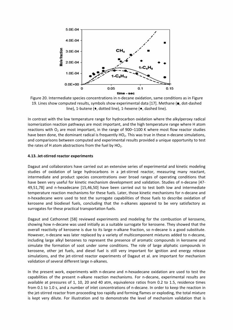
Figure 20. Intermediate species concentrations in n‐decane oxidation, same conditions as in Figure 19. Lines show computed results, symbols show experimental data [17]. Methane (■, dot‐dashed
line), 1‐butene (♦, dotted line), 1‐hexene (●, dashed line). In contrast with the low temperature range for hydrocarbon oxidation where the alkylperoxy radical isomerization reaction pathways are most important, and the high temperature range where H atom reactions with O2 are most important, in the range of 900–1100 K where most flow reactor studies have been done, the dominant radical is frequently HO2. This was true in these n‐decane simulations, and comparisons between computed and experimental results provided a unique opportunity to test the rates of H atom abstractions from the fuel by HO2. 4.13. Jet‐stirred reactor experiments Dagaut and collaborators have carried out an extensive series of experimental and kinetic modeling studies of oxidation of large hydrocarbons in a jet‐stirred reactor, measuring many reactant, intermediate and product species concentrations over broad ranges of operating conditions that have been very useful for kinetic mechanism development and validation. Studies of n‐decane [47‐49,51,78] and n‐hexadecane [15,46,50] have been carried out to test both low and intermediate temperature reaction mechanisms for these fuels. Later, those kinetic mechanisms for n‐decane and n‐hexadecane were used to test the surrogate capabilities of those fuels to describe oxidation of kerosene and biodiesel fuels, concluding that the n‐alkanes appeared to be very satisfactory as surrogates for these practical transportation fuels. Dagaut and Cathonnet [58] reviewed experiments and modeling for the combustion of kerosene, showing how n‐decane was used initially as a suitable surrogate for kerosene. They showed that the overall reactivity of kerosene is due to its large n‐alkane fraction, so n‐decane is a good substitute. However, n‐decane was later replaced by a variety of multicomponent mixtures added to n‐decane, including large alkyl benzenes to represent the presence of aromatic compounds in kerosene and simulate the formation of soot under some conditions. The role of large aliphatic compounds in kerosene, other jet fuels, and diesel fuel is still very important for ignition and energy release simulations, and the jet‐stirred reactor experiments of Dagaut et al. are important for mechanism validation of several different large n‐alkanes. In the present work, experiments with n‐decane and n‐hexadecane oxidation are used to test the capabilities of the present n‐alkane reaction mechanisms. For n‐decane, experimental results are available at pressures of 1, 10, 20 and 40 atm, equivalence ratios from 0.2 to 1.5, residence times from 0.1 to 1.0 s, and a number of inlet concentrations of n‐decane. In order to keep the reaction in the jet‐stirred reactor from proceeding too rapidly and forming flames or exploding, the total mixture is kept very dilute. For illustration and to demonstrate the level of mechanism validation that is

possible with these experiments, below we show comparisons between experimental and computed results for two different stoichiometric mixtures at 10 atm pressure. 4.14. Test 11: Low and intermediate temperature jet‐stirred reactor oxidation of n‐decane Dagaut et al. [78] carried out an early study of oxidation of n‐decane over an especially wide range of temperatures, from 550 to 1150 K, which includes the entire negative temperature coefficient (NTC) range and into the beginning of the high temperature regime. This provides a unique opportunity to test the kinetic mechanism for n‐decane over this wide range of temperatures. The example used for comparisons with the present kinetic model was for stoichiometric n‐decane/oxygen/nitrogen, with an initial n‐decane mole fraction of 0.1%, at 10 atm pressure, reactor residence time of 1 s, over a temperature range from 550 to 1150 K. More than 20 distinct stable species mole fractions were measured as functions of the reactor temperature. Comparisons between computed and experimental mole fractions for n‐decane, methane and formaldehyde are shown in Figure 21, with comparable results for CO, CO2 and propene in Figure 22. The fuel, CO and CO2 profiles show strong indications of NTC behavior, with somewhat less NTC behavior for propene and formaldehyde and very little NTC behavior for methane. The agreement between computed and experimental results is excellent for all the species in Figures 21 and 22, with the exception of CO2, for which the kinetic model shows less low temperature production of CO2, although the mechanism accurately reproduces its higher temperature behavior. Overall agreement with other species was also very good, including both the low temperature (550–750 K) and the intermediate temperature (750–1000 K) regimes.
Figure. 21. Jet‐stirred reactor oxidation of 0.1% n‐decane, ϕ = 1, 10 atm pressure, residence time of 1 s. Experiments from Dagaut et al. [78] are filled symbols, computed results are open symbols
connected by lines.

Figure 22. Jet‐stirred reactor oxidation of 0.1% n‐decane, ϕ = 1, 10 atm pressure, residence time of 1 s. Experiments from Dagaut et al. [78] are filled symbols, computed results are open symbols
connected by lines. In the low temperature regime, Dagaut et al. [78] measured the mole fractions of the major cyclic ethers, including tetrahydropyrans, tetrahydrofurans, oxitanes and oxiranes which contain cyclic structures with one O‐atom and 5, 4, 3, and 2 C atoms, respectively. These cyclic compounds are critical features of the low temperature alkylperoxy radical isomerization reaction pathways that lead to two‐stage autoignition and properties including octane numbers for gasolines [6,65]. Specifically, the reaction pathways producting tetrahydrofurans are the only pathways that provide chain branching at low temperatures, while those pathways leading to oxirans, oxetans and tetrahydropyrans lead to chain propagation, so the ratios of these cyclic ethers are important metrics for low temperature ignitability. Very few combustion kinetics measurements have been made of their relative production rates in carefully controlled experiments, so the experimental results of Dagaut et al. [78] are especially valuable. In their experiments, tetrahydrofurans were produced at much greater rates than any of the other cyclic ether classes, and the two cyclic ethers with highest concentrations were 2‐methyl‐5‐pentyl‐tetrahydrofuran (C10O2‐5 in our mechanism) and 2‐ethyl‐5‐butyl‐tetrafuran (C10O3‐6), followed by 2,5‐dipropyl‐tetrahydrofuran (C10O4‐7) and 2‐hexyl‐tetrahydrofuran (C10O1‐4). In the experiments of Dagaut et al., relative amounts of formation of these tetrahydrofurans was reported as (1.51, 1.48, 0.96, 0.30), respectively. Measured profiles as functions of reactor temperature are compared with the computed values in Figure 23 (the profile of C10O1‐4 was not reported by Dagaut et al.). Measured and computed values are in very good agreement, and the relative levels of the first 3 tetrahydrofurans are in excellent agreement. The observation that the tetrahydrofurans were the only major cyclic ethers in these experiments is also reproduced by the model.

Figure 23. Mole fractions of tetrahydrofurans in jet‐stirred reactor at ϕ = 1, 10 atm pressure, 0.1% n‐decane in nitrogen, 1 s residence time. Symbols are experimental results [78], lines are computed.
Black line shows computed results for C10O1‐4 (2‐hexyl‐tetrahydrofuran). 4.15. Test 12: Intermediate temperature jet‐stirred reactor oxidation of n‐decane Dagaut et al. [48] reported a study of n‐decane and kerosene combustion at 10 atm pressure in the jet‐stirred reactor. A detailed kinetic model was also developed, intended for intermediate temperature systems (873–1033 K), which reproduced the observations quite well for most species. An important accomplishment of this paper was its demonstration that the n‐decane fuel produced nearly identical intermediate and product distributions as the kerosene, so n‐decane was established as a reliable surrogate for jet fuel/kerosene. The example used here describes a dilute (1000 ppm fuel) stoichiometric mixture of n‐decane and oxygen, at 10 atm pressure and a residence time in the stirred reactor of 0.5 s. Figure 24 shows the computed and experimental values for 5 species for which measured values were reported, with good agreement between model and experiment.
Figure 24. Chemical species concentrations in a jet‐stirred reactor oxidation of n‐decane, 10 atm
pressure, 1000 ppm n‐decane, ϕ = 1.0, residence time of 0.5 s. Lines represent computed values, symbols are experimental results [48].

Other interesting kinetic information from this simulation includes the relative levels of the C10 olefins and the 1‐olefins for species with fewer than 10 carbon atoms. The decenes are shown in Figure 25, together with the concentration of the n‐decane fuel.
Figure 25. Computed levels of decenes produced in oxidation of n‐decane in jet‐stirred reactor, same
conditions as in Figure 24. Concentration of n‐decane is shown for comparison. The decenes have their highest concentrations at relatively low temperatures, where the fuel consumption rate is greatest. Production of conjugate olefins during n‐alkane oxidation is relatively difficult because it requires breaking a C‐H bond following H atom abstraction from the fuel, rather than breaking a C‐C bond via β‐scission, which is faster at temperatures around 800 K. The 1‐decene is produced at low rates because it requires breaking a primary CH bond with its higher bond energy, rather than a secondary C‐H bond. The 5‐decene also is produced at lower levels because it has only one reaction sequence for production, in contrast to the multiple formation pathways for the 2‐, 3‐, and 4‐decenes. For the olefins with fewer than 10 carbon atoms, the present mechanism predicts that 1‐olefins have much higher concentrations than the other olefins with the same number of carbon atoms. This trend is easy to explain as a result of β‐scission of alkyl radicals produced from H atom abstraction from n‐decane, and the pattern is observed for combustion of all of the n‐alkanes in both kinetic modeling and experiments. The relative concentrations of 1‐olefins produced from n‐decane are shown in Figure 26, showing that those olefins with multiple production reaction pathways have much higher concentrations than those with more limited production pathways with higher energy barriers. Note that the C9 1‐olefin, like the 1‐decene discussed above, has a very low concentration, due to its unique production path which requires abstraction of an H‐atom from the 3‐site in n‐decane followed by breaking the C‐C bond between the first and second carbon atoms in the linear chain.

Figure 26. Concentrations of 1‐olefins produced during oxidation of n‐decane in a jet‐stirred reactor.
Same conditions as Figure 24. The same trend, in which the principal olefins produced are 1‐olefins, and the selectivity increases with decreasing 1‐olefin length as seen in Figure 26, was noted above in the pyrolysis mechanism tests shown in Figures 2 and 3, and it is a general feature of n‐alkane oxidation reaction pathways. 4.16. Test 13: Intermediate temperature jet‐stirred reactor oxidation of n‐hexadecane and rapeseed methyl ester fuel Experimental and computed results were reported for stirred reactor oxidation of n‐hexadecane by Ristori et al. [46,50], and additional kinetic analysis and modeling of the same experiments were reported by Fournet et al. [15]. The present kinetic mechanism for n‐hexadecane was used to calculate the species profiles for each of the n‐hexadecane experiments, which included mixtures at
ϕ=0.5, 1.0 and 1.5, all with initial mole fraction of n‐hexadecane of 0.03%, diluted in N2, at atmospheric pressure, over a temperature range from 1000 to 1250 K, with a residence time of 0.07 s. The same experiments were used to validate the previous modeling studies of Dagaut et al. [46,50] and Fournet et al. [15], and the agreement between the experimental data and the present computed results was good, and very comparable to those previous studies. Examples of these comparisons are shown in Figure 27 for several of the measured chemical species, for the fuel‐rich
case at ϕ=1.5.
Figure 27. Comparison between computed and experimental [46] results for selected species in
n‐C16H34 oxidation in a JSR. Conditions are ϕ = 1.5, 1 atm pressure, and 0.07 s residence time.

These are complex mechanisms for such large fuel molecules, and judging only from the JSR simulations, it appears that the mechanism produces the observed intermediates with reasonable accuracy, but there are many areas in which greater precision is desirable, and considerable further study is needed. Recently, Dagaut et al. [53] used a kinetic mechanism for n‐hexadecane to simulate combustion of rapeseed methyl ester (RME) biodiesel fuel in a JSR. The overall agreement between experimental RME species measurements and computed species levels for n‐hexadecane fuel was very good. The largest disagreement was for CO2 at temperatures below 1100 K, where the experiments indicated concentrations of CO2 much higher than the computed values, especially at lower reactor temperatures. These simulations were repeated with the present n‐hexadecane kinetic mechanism, with initial mole fractions of 0.0005625 n‐C16H34, 0.011 O2 and N2 diluent, and the results for the major species are shown in Figure 28.
Figure 28. Major species profiles in JSR oxidation, comparing RME experiments [53] and present
n‐hexadecane model. Conditions are stoichiometric, 1 atm, 0.07 s residence time. As in Dagaut et al. [53], the overall agreement is very good. Similar agreement was observed for most other species; for example, the computed level of 1‐C6H12 reached a peak mole fraction of 6×10⁻⁵ at 1000 K, and the peak mole fraction of the same species was measured to be 4×10⁻⁵ at the same temperature. Also in agreement with Dagaut et al., the most significant difference between calculations and experiments was found to be the CO2 levels at lower temperatures as seen in Figure 28. This difference is due to the methyl ester group in RME, which produces CO2 at temperatures below 1100 K directly during fuel decomposition, rather than via oxidation of CO, which is delayed until higher temperatures during oxidation of n‐hexadecane. Low temperature production of CO2 from a methyl ester group has been observed in other large methyl ester fuels [23,88], and the peak in CO2 mole fraction at 950–1000 K in Figure 28 is a “signature” of methyl ester oxidation that is not reproduced during oxidation of n‐alkanes. Otherwise, it appears that n‐alkanes can reproduce many of the combustion characteristics of large methyl esters, as first shown by Dagaut et al. [53]. 4.17. Test 14: Intermediate temperature jet‐stirred reactor oxidation of n‐decane and kinetic modeling computations of oxidation of n‐alkanes from n‐octane through n‐hexadecane In a series of jet‐stirred reactor experiments, Dagaut et al. [51] reported results from a family of n‐decane/O2/N2 mixtures, with very dilute inlet fuel concentrations (700 ppm n‐decane), a residence time of 0.07 s, at atmospheric pressure, over a wide range of oxygen concentrations from lean to rich. We used the present kinetic mechanisms for the n‐alkanes to carry out a series of numerical

experiments under the same jet‐stirred reactor conditions as those reported by Dagaut et al. We calculated stoichiometric cases for n‐octane, n‐decane, n‐dodecane, n‐tetradecane and n‐hexadecane. We scaled the inlet concentrations for each n‐alkane to match the carbon atom flux with that for n‐decane; therefore the inlet levels were (n‐octane/O2) = (875 ppm/10938 ppm), for n‐decane (700 ppm/10850 ppm), for n‐dodecane (583 ppm/10750 ppm), for n‐tetradecane (500 ppm/10750 ppm), and for n‐hexadecane (438 ppm/10718 ppm). This approximately also scales the total H atom flux, although the H atom amounts change slightly while the carbon content remains constant. The results of the jet‐stirred reactor calculations are shown in Figure 29, showing the fuel concentrations for n‐octane, n‐decane and n‐dodecane, under conditions of constant C atom input flux. The fuel mole fraction curves are different in order to keep the carbon flux constant for all of the mixtures, but an interesting result is observed for nearly all of the other species in the group of calculations, as shown in Figure 30 in which the levels of ethene, methane and 1‐butene are plotted during the computed oxidation of n‐octane, n‐decane, n‐dodecane, n‐tetradecane and n‐hexadecane. The computed concentrations of these species, and most others not shown, are very nearly equal to each other, regardless of the n‐alkane fuel being used. There are minor trends in the species levels shown in Figure 30; at 1000 K, the highest levels of methane and ethane are for n‐hexadecane and the lowest values are for n‐octane, with the opposite trend in the levels of 1‐butene. However, the main conclusion from Figure 30 is that the species levels are so nearly identical for all of the n‐alkanes. Experimentally measured values for the n‐decane case are shown in Figure 30. From these results, it appears that any large n‐alkane fuel could serve as a reliable surrogate for any of the others, as long as the fuel level is properly scaled. For example, n‐octane or n‐decane would be very acceptable surrogates for a larger fuel such as n‐hexadecane, thereby reducing significantly the computational costs of kinetic simulations. The only species not reliably simulated with this approach are the larger stable species associated with the larger fuel that are not included in the mechanism for the smaller surrogate fuel.
Figure 29. Fuel concentrations in jet‐stirred reactor simulations. Initial values are scaled to 700 ppm in n‐decane for comparison. Mixtures are stoichiometric, 1 atm pressure, residence time of 0.07 s. Experimental values are shown for n‐decane (symbols) [51]. Lines are computed results for n‐octane
(dotted), n‐decane (solid), n‐dodecane (dashed).

Figure. 30. Computed concentrations of ethene (solid lines), methane (dashed lines) and 1‐butene
(dotted lines) for n‐alkane fuels under jet‐stirred reactor conditions. Symbols represent experimental
values from Dagaut et al. [51] for n‐decane oxidation, ethene (□), methane (◊), and 1‐butene (△). As noted by Dagaut and Cathonnet [58], n‐decane can reproduce the overall reactivity, heat release and many intermediate species levels in combustion of kerosene jet fuel, but this approach is still unable to address other questions such as sooting and the influences of aromatic species in the kerosene fuel. When the fuel itself includes significant amounts of aromatic species, then use of a multicomponent surrogate mixture which includes a relevant aromatic compound is required. For this reason, Dagaut and Cathonnet included n‐propyl benzene and n‐propyl cyclohexane with n‐decane to provide a more realistic kerosene surrogate. 4.18. Test 15: Low temperature pressurized flow reactor oxidation of n‐dodecane Agosta et al. [79] used a pressurized flow reactor to study autoignition and combustion of several components of a proposed surrogate jet fuel. One of the components was n‐dodecane, and they used a semi‐detailed kinetic model to analyze their measured results, showing reasonably good agreement. Related analysis of the same measurements was carried out in a larger study of semi‐detailed kinetic mechanisms by Ranzi et al. [21]. We have used the same experimental data to test the present mechanism for n‐dodecane. The experiments on n‐dodecane were carried out at 8 atm pressure for dilute lean mixtures. The inlet temperature of the reactants and nitrogen diluent was varied slowly from about 900 K down to about 600 K, and the overall reactivity was determined by measuring the CO concentrations in the reacting gases after an experimental residence time of 120 ms. The time constant for the inlet temperature variation is much longer than the reactant residence time in the flow reactor, so the reacting conditions are assumed locally time independent. Detailed simulations of these pressurized
flow reactor experiments focused on two cases at equivalence ratio of ϕ =0.2 and 0.3, and the resulting CO results are compared with the experimental data in Figure 31.

Figure 31. Computed and experimental CO concentrations in pressurized flow reactor [79] oxidation of n‐dodecane, at 8 atm, residence time of 120 ms. Computed values are shown for curves with filled
symbols, experiments with open symbols, ϕ = 0.2 (◊ and ), and ϕ = 0.3 ( and ). All n‐alkane oxidation in the temperature range of these pressurized flow reactor experiments is strongly influenced by low temperature, alkylperoxy radical isomerization kinetics, and production of CO is part of that reaction sequence. The degree of agreement between measured and computed values in Figure 31 is a very demanding test of the validity of the kinetic mechanism. At both values of equivalence ratio, the kinetic model shows that the peak reaction zone is shifted slightly towards lower temperatures, compared to the measurements. The same type of shift toward lower temperatures was observed by Ranzi et al. using their semi‐detailed or lumped kinetic model, although the shift was less in their simulations than that shown in Figure 31. The good agreement in the absolute peak levels of CO also provides support for the reaction mechanism. 5. Summary Kinetic mechanisms for the large n‐alkanes described and tested here extend to much larger n‐alkanes modeling capabilities that have been available for n‐heptane for some years. Attention has been given to providing the same level of kinetic detail that was contained in the previous n‐heptane mechanism, so the experience that has been developed using the n‐heptane mechanism is directly applicable to these larger fuels. The greater size of the new mechanisms make mechanism reduction an even more serious challenge than before, so these mechanisms should provide a valuable set of mechanisms to test reduction systems. The lumping techniques of Dryer [17] and Ranzi [21,34] have already been applied to mechanisms similar to the present group. These mechanisms also should be valuable for developing surrogate fuels [1‐4] for practical systems and for unique systems such as biodiesel fuels. Large n‐alkanes are prominent in transportation fuels, so the present mechanisms may be useful in making surrogate fuel mixtures more realistic than previously possible. A more subtle impact on surrogate fuel definitions is provided by the n‐alkane intercomparisons above showing that ignition and combustion of the n‐alkanes from octane through hexadecane are remarkably similar. Ignition (see Figure 10) and oxidation (see Figure 30) of the n‐alkanes, while not identical, are sufficiently similar that they can be exchanged for each other in many application simulations. This explains why our earlier n‐heptane mechanism [9] has been so useful as a diesel fuel surrogate in past studies, despite its smaller size than conventional diesel fuel molecules; its ignition rate is close enough to those of real diesel fuels, whose ignition rate and cetane number are established by its large n‐alkane components, that diesel ignition is quite well reproduced by n‐heptane.

Recent work of Dagaut et al. [52,53] has successfully used large n‐alkanes as useful surrogates for kerosene and biodiesel fuels. The present work shows that the long straight‐chain structure of the n‐alkanes controls their ignition, and this clearly extends to long straight‐chain molecules with additional functional groups attached to the end of the chain. Large n‐alkanes should be successful as surrogates for other chemical species with similar structures, especially long‐chain n‐alkyl benzenes and n‐alkyl cyclohexanes and cyclopentanes [51]. Some prominent engine modeling groups [89] are building surrogates for biodiesel fuels by combining a large n‐alkane such as n‐heptane or n‐decane with a smaller methyl ester such as methyl butanoate; the n‐alkane then reproduces the ignition properties of the biodiesel while the small methyl ester reproduces the low temperature early production of CO and CO2. A wider range of n‐alkanes for which kinetic reaction mechanisms are available can enhance such biodiesel surrogate modeling efforts. These mechanisms have been developed in somewhat simplified forms. We are aware of numerous improvements that would make them more general and more applicable to new systems. Perhaps most important are extensions that would make them more specific towards kinetic modeling of olefins. Other refinements should provide a more accurate theoretical description of some kinetic processes, as well as more accurate extensions to much higher pressures. Of course, mechanism upgrades and refinements add more complexity and computational costs to detailed modeling efforts. However, in the present form, these mechanisms provide capabilities for simulation of combustion of n‐alkane fuels. Acknowledgments The authors thank Prof. F. Battin‐Leclerc for many valuable discussions and Prof. C.J. Sung for experimental RCM results prior to publication. This work was supported by the U.S. Department of Energy, Office of Freedom CAR and Vehicle Technologies, and the authors thank program managers Kevin Stork and Gurpreet Singh for their support of this work. This work was performed under the auspices of the U.S. Department of Energy by the Lawrence Livermore National Laboratory under Contract DE‐AC52‐07NA27344. References [1]W.J. Pitz, N.P. Cernansky, F.L. Dryer, F.N. Egolfopoulos, J.T. Farrell, D.G. Friend, H. Pitsch, Society of Automotive Engineers, paper SAE‐2007‐01‐0175, 2007 [2]J.T. Farrell, N.P. Cernansky, F.L. Dryer, D.G. Friend, C.A. Hergart, C.K. Law, R.M. McDavid, C.J. Mueller, A.K. Patel, H. Pitsch, Society of Automotive Engineers, paper SAE‐2007‐01‐0201, 2007 [3]A. Violi, S. Yan, E.G. Eddings, A. Sarofim, S. Granata, T. Faravelli, E. Ranzi Combust. Sci. Technol., 174 (2002), pp. 399–417 [4]M. Colket, T. Edwards, S. Williams, N.P. Cernansky, D.L. Miller, F. Egolfopoulos, P. Lindstedt, K. Seshadri, F.L. Dryer, C.K. Law, D. Friend, D.B. Lenhert, H. Pitsch, A. Sarofim, M. Smooke, W. Tsang, AIAA publication AIAA‐2007‐0770, 2007 [5]W.G. Lovell Ind. Eng. Chem., 40 (1948), pp. 2388–2438 [6]C.K. Westbrook, W.J. Pitz, W.R. Leppard, Society of Automotive Engineers, paper SAE‐912314, 1991 [7]C.K. Westbrook, W.J. Pitz, J.E. Boercker, H.J. Curran, J.F. Griffiths, C. Mohamed, M. Ribaucour

Proc. Combust. Inst., 29 (2002), pp. 1311–1318 [8]M. Ribaucour, R. Minetti, L.R. Sochet, H.J. Curran, W.J. Pitz, C.K. Westbrook Proc. Combust. Inst., 28 (2000), pp. 1671–1678 [9]H.J. Curran, P. Gaffuri, W.J. Pitz, C.K. Westbrook Combust. Flame, 114 (1998), pp. 149–177 [10]H.J. Curran, P. Gaffuri, W.J. Pitz, C.K. Westbrook Combust. Flame, 129 (2002), pp. 253–280 [11]E.S. Blurock J. Chem. Inf. Comput. Sci., 44 (2004), pp. 1336–1347 [12]G. Moréac, E.S. Blurock, F. Mauss Combust. Sci. Technol., 178 (2006), pp. 2025–2038 [13]G. Bikas, N. Peters Combust. Flame, 126 (2001), pp. 1456–1475 [14]F. Battin‐Leclerc, R. Fournet, P.A. Glaude, B. Judenherc, V. Warth, G.M. Côme, G. Scacchi Proc. Combust. Inst., 28 (2000), pp. 1597–1605 [15]R. Fournet, F. Battin‐Leclert, P.A. Glaude, B. Judenherc, V. Warth, G.M. Côme, G. Scacchi, A. Ristori, G. Pengloan, P. Dagaut, M. Cathonnet Int. J. Chem. Kinet., 33 (2001), pp. 574–586 [16]G. Vanhove, R. Minetti, S. Touchard, R. Fournet, P.A. Glaude, F. Battin‐Leclerc Combust. Flame, 145 (2006), pp. 272–281 [17]S.P. Zeppieri, S.D. Klotz, F.L. Dryer Proc. Combust. Inst., 28 (2000), pp. 1587–1595 [18]T.J. Held, A.J. Marchese, F.L. Dryer Combust. Sci. Technol., 123 (1997), pp. 107–146 [19]O. Herbinet, P.‐M. Marquaire, F. Battin‐Leclerc, R. Fournet J. Anal. Appl. Pyrolysis, 78 (2007), pp. 419–429 [20]F. Buda, R. Bounaceur, V. Warth, P.A. Glaude, R. Fournet, F. Battin‐Leclerc Combust. Flame, 142 (2005), pp. 170–186 [21]E. Ranzi, A. Frassoldati, S. Granata, T. Faravelli Ind. Eng. Chem. Res., 44 (2005), pp. 5170–5183 [22]M. Mehl, G. Vanhove, W.J. Pitz, E. Ranzi, Combust. Flame (2008), doi:10.1016/j.combustflame.2008.07.004, in press [23]O. Herbinet, W.J. Pitz, C.K. Westbrook Combust. Flame, 154 (2008), pp. 507–528 [24]C.K. Westbrook, F.L. Dryer

Proc. Combust. Inst., 18 (1980), pp. 749–767 [25]C.K. Westbrook, F.L. Dryer Prog. Energy Combust. Sci., 10 (1980), pp. 1–57 [26]C.K. Westbrook, F.L. Dryer Combust. Sci. Technol., 20 (1979), pp. 125–140 [27]C.K. Westbrook, W.J. Pitz Combust. Sci. Technol., 37 (1984), pp. 117–152 [28]W.J. Pitz, C.K. Westbrook, W.M. Proscia, F.L. Dryer Proc. Combust. Inst., 20 (1984), pp. 831–843 [29]J. Li, Z.W. Zhao, A. Kazakov, M. Chaos, F.L. Dryer, J.J. Scire Int. J. Chem. Kinet., 39 (2007), pp. 109–136 [30]J. Li, Z.W. Zhao, A. Kazakov, F.L. Dryer Int. J. Chem. Kinet., 36 (2004), pp. 566–575 [31]M. O'Conaire, H.J. Curran, J.M. Simmie, W.J. Pitz, C.K. Westbrook Int. J. Chem. Kinet., 36 (2004), pp. 603–622 [32]T.J. Held, F.L. Dryer Int. J. Chem. Kinet., 30 (1998), pp. 805–830 [33]S. Hochgreb, F.L. Dryer Combust. Flame, 91 (1992), pp. 257–284 [34]E. Ranzi, A. Sogaro, P. Gaffuri, G. Pennati, C.K. Westbrook, W.J. Pitz Combust. Flame, 99 (1994), pp. 201–211 [35]C. Chevalier, E.J. Pitz, J. Warnatz, C.K. Westbrook, H. Melenk Proc. Combust. Inst., 24 (1992), pp. 93–101 [36]M. Nehse, J. Warnatz, C. Chevalier Proc. Combust. Inst., 26 (1996), pp. 773–780 [37]Y. Muharam, J. Warnatz Phys. Chem. Chem. Phys. (2007), pp. 4218–4229 [38]V. Warth, N. Stef, P.A. Glaude, F. Battin‐Leclerc, G. Scacchi, G.M. Côme Combust. Flame, 114 (1998), pp. 81–102 [39]V. Warth, F. Battin‐Leclerc, R. Fournet, P.A. Glaude, G.M. Côme, G. Scacchi Comput. Chem., 24 (2000), pp. 541–560 [40]P.A. Glaude, V. Warth, R. Fournet, F. Battin‐Leclerc, G. Schacchi, G.M. Côme Int. J. Chem. Kinet., 30 (1998), pp. 949–959 [41]G. Dayma, P.A. Glaude, R. Fournet, F. Battin‐Leclerc Int. J. Chem. Kinet., 35 (2003), pp. 273–285

[42]F. Buda, B. Heyberger, R. Fournet, P.‐A. Glaude, V. Warth, F. Battin‐Leclerc Energy Fuels, 20 (2006), pp. 1450–1459 [43]S. Touchard, R. Fournet, P.A. Glaude, V. Warth, F. Battin‐Leclerc, G. Vanhove, M. Ribaucour, R. Minetti Proc. Combust. Inst., 30 (2005), p. 1073 [44]S. Touchard, F. Buda, G. Dayma, P.A. Glaude, R. Fournet, F. Battin‐Leclerc Int. J. Chem. Kinet., 37 (2005), pp. 451–463 [45]R. Bounaceur, P.A. Glaude, R. Fournet, F. Battin‐Leclerc, S. Jay, A. Pires da Cruz Int. J. Vehicle Design, 44 (2007), pp. 124–142 [46]A. Ristori, P. Dagaut, M. Cathonnet Combust. Flame, 125 (2001), pp. 1128–1137 [47]C. Balès‐Guéret, M. Cathonnet, J.‐C. Boettner, F. Gaillard Energy Fuels, 6 (1992), pp. 189–194 [48]P. Dagaut, M. Reuillon, J.‐C. Boettner, M. Cathonnet Proc. Combust. Inst., 25 (1994), pp. 919–926 [49]P. Dagaut, M. Reuillon, M. Cathonnet Combust. Sci. Technol., 103 (1994), pp. 349–359 [50]P. Dagaut Phys. Chem. Chem. Phys., 4 (2002), pp. 2079–2094 [51]P. Dagaut, A. El Bakali, A. Ristori Fuel, 85 (2006), pp. 944–956 [52]P. Dagaut, S. Gaïl J. Phys. Chem. A, 111 (2007), pp. 3992–4000 [53]P. Dagaut, S. Gaïl, M. Sahasrabudhe Proc. Combust. Inst., 31 (2007), pp. 2955–2961 [54]E. Olchanski, A. Burcat Int. J. Chem. Kinet., 38 (2006), pp. 703–713 [55]K.D. Dahm, P.S. Virk, R. Bounaceur, F. Battin‐Leclerc, P.M. Marquaire, R. Fournet, E. Daniau, M. Bouchez J. Anal. Appl. Pyrolysis, 71 (2004), pp. 865–881 [56]R.P. Lindstedt, L.Q. Maurice Combust. Sci. Technol., 107 (1995), pp. 317–353 [57]R.P. Lindstedt, L.Q. Maurice J. Prop. Power, 16 (2000), pp. 187–195 [58]P. Dagaut, M. Cathonnet

Prog. Energy Combust. Sci., 32 (2006), pp. 48–92 [59]F. Battin‐Leclerc, Prog. Energy Combust. Sci. (2008), in press [60]N. Cohen, K.R. Westberg Int. J. Chem. Kinet., 18 (1986), pp. 99–140 [61]N. Cohen Int. J. Chem. Kinet., 23 (1991), pp. 683–700 [62]E.R. Ritter, J.W. Bozzelli Int. J. Chem. Kinet., 23 (1991), pp. 767–778 [63]J. Yu, R. Sumathi, W.H. Green J. Am. Chem. Soc., 126 (2004), pp. 12685–12700 [64]E.J. Silke, W.J. Pitz, C.K. Westbrook, M. Ribaucour J. Phys. Chem. A, 111 (19) (2007), pp. 3761–3775 [65]R.T. Pollard C.H. Bamford, C.F.H. Tipper (Eds.), Comprehensive Chemical Kinetics, vol. 17Elsevier, New York (1977), p. 249 [66]H. Sun, J.W. Bozzelli J. Phys. Chem. A, 108 (10) (2004), pp. 1694–1711 [67]C.Y. Sheng, J.W. Bozzelli, A.M. Dean, A.Y. Chang J. Phys. Chem. A, 106 (2002), pp. 7276–7293 [68]J.D. DeSain, S.J. Klippenstein, J.A. Miller, C.A. Taatjes J. Phys. Chem. A, 107 (2003), pp. 4415–4427 [69]H. Carstensen, C.V. Naik, A.M. Dean J. Phys. Chem. A, 109 (2005), pp. 2264–2281 [70]E.L. Petersen, D.M. Kalitan, S. Simmons, G. Bourque, H.J. Curran, J.M. Simmie Proc. Combust. Inst., 31 (2007), pp. 447–454 [71]P. Zhou, O.L. Hollis, B.L. Crynes Ind. Eng. Chem. Res., 26 (1987), pp. 846–852 [72]D.F. Davidson, J.T. Herbon, D.C. Horning, R.K. Hanson Int. J. Chem. Kinet., 33 (2001), pp. 775–783 [73]D.C. Horning, D.F. Davidson, R.K. Hanson J. Propul. Power, 18 (2002), pp. 363–371 [74]U. Pfahl, K. Fieweger, G. Adomeit Proc. Combust. Inst., 26 (1996), pp. 781–789 [75]V.P. Zhukov, V.A. Sechenov, A.Y. Starikovskii Combust. Flame, 153 (2008), pp. 130–136

[76]V.P. Zhukov, D.L. Tsyganov, V.A. Sechenov, A.Y. Starikovskii, Proceedings of the European Combustion Meeting, Belgium, April, 2005 [77]K. Kumar, G. Mittal, C.J. Sung, Paper D05, in: Fifth US Combustion Meeting, March 25–28, 2007 [78]P. Dagaut, M. Reuillon, M. Cathonnet, D. Voisin J. Chim. Phys., 92 (1995), pp. 47–76 [79]A. Agosta, N.P. Cernansky, D.L. Miller, T. Faravelli, E. Ranzi Exp. Therm. Fluid Sci., 28 (2004), pp. 701–708 [80]W. Tsang, R.F. Hampson J. Phys. Chem. Ref. Data, 15 (1986), pp. 1087–1279 [81]H.K. Ciezki, G. Adomeit Combust. Flame, 93 (1993), pp. 421–433 [82]K. Fieweger, R. Blumenthal, G. Adomeit Combust. Flame, 109 (1997), pp. 599–619 [83]E.L. Petersen, M. Lamnaouer, J. de Vries, H. Curran, J. Simmie, M. Fikri, C. Schulz, G. Bourque, Proc. Int. Symp. Shock Waves, July, 2007 [84]M. Chaos, F.L. Dryer Combust. Sci. Technol., 180 (2008), pp. 1051–1094 [85]F.L. Dryer, M. Chaos Combust. Flame, 152 (2008), pp. 293–299 [86]S.S. Vasu, D.F. Davidson, Z. Hong, V. Vasudevan, R.K. Hanson, Proc. Combust. Inst. 32 (2009), in press [87]A. Cox, J.F. Griffiths, C. Mohamed, H.J. Curran, W.J. Pitz, C.K. Westbrook Proc. Combust. Inst., 26 (1996), pp. 2685–2692 [88]C.K. Westbrook, W.J. Pitz, H.J. Curran J. Phys. Chem. A, 110 (2006), pp. 6912–6922 [89]R.D. Reitz, University of Wisconsin Engine Research Center, personal communication, 2008