Embed Size (px)
Citation preview

Electr EngDOI 10.1007/s00202-017-0559-6
ORIGINAL PAPER
A comprehensive comparison of STATCOM versus SVC-basedfuzzy controller for stability improvement of wind farm connectedto multi-machine power system
M. G. Hemeida1 · Hegazy Rezk1,2 · Mohamed M. Hamada1
Received: 28 October 2016 / Accepted: 5 May 2017© Springer-Verlag Berlin Heidelberg 2017
Abstract Stabilization of wind farm (WF) is consideredone of the major serious issues for developing power sys-tems based on renewable energy sources. A comparisonof dynamic performances for FACTS devices like STAT-COM and SVC is presented in this paper. Such devicesare employed to stabilize WF integrated with multi-machinepower system (WFMPS). Fuzzy logic controller (FLC) hasbeen employed for controlling FACTS devices to enhanceWFMPS performance under different abnormal conditions.Three-phase to ground short circuit fault has been takeninto consideration in different locations of system. MAT-LAB/Simulink is used to perform the modeling and sim-ulation of WFMPS. The obtained results demonstrate theeffect of both SVC- and STATCOM-based FLC on dampingthe system oscillations and improving the system dynamicperformance in the post-fault duration. The comparison con-firms superior dynamic performance and fast fault recoveryof STATCOM-based FLC through different fault conditionscompared with SVC-based FLC.
Keywords Wind energy system · STATCOM · SVC andfuzzy logic control
B Hegazy [email protected]
1 Electrical Engineering Department, Faculty of Engineering,Minia University, Minya, Egypt
2 College of Engineering at Wadi Aldawaser, Prince Sattam binAbdulaziz University, P.O. Box 54, Wadi Aldawaser 11991,Saudi Arabia
1 Introduction
Renewable energy systems that do not need fuel and do notaffect the environment have been considered an essential sig-nificance due to scarcity of fossil fuel [1,2]. Furthermore,increasing of electrical energy demand and growing envi-ronmental concerns. Wind power is the primary source inEurope and USA in 2015. 63 GW has been added during2015; therefore, the total installed capacity of wind energysystems (WESs) reaches up to 433 GW around the world.Figure 1 displays worldwide wind power capacity and yearlyadditions during the period from 2005 into 2015. The top 10countries,which have the highest capacity ofWESs, are illus-trated in Fig. 2. WESs are playing a main role for supplyingelectricity demand in many countries such as Denmark (42%of demand in 2015), Germany (60%) and Uruguay (15.5%)[3]. Accordingly, impacts of WES on utility grid (UG) havea huge attention from researchers. Besides its high capacity,WES has been considered cost competitive and environmen-tally friendly [4]. SCIG, PMSG and DFIG are consideredessential types of wind power generators. DFIG is widelyused in the WES due to its flexibility in control and highefficiency [5].
Today, wind farm (WF) connected to grid is used fre-quently. Therefore, its transient and dynamic performanceenhancement became an essential issue and received a hugeinterest from researchers. The flexible AC transmission sys-tems (FACTS) can be employed for ensuring power qualityof WF. They are perfect compensators for solving systemtroubles due to nonlinear loads and abnormal conditions.It has been considered the best solution to enhance perfor-mance of WF fed to UG as well as multi-machine systems.FACTS devices include different configurations like STAT-COM, SVC and UPFC [6]. STATCOM can generate andabsorb reactive power for controlling parameters of WES.
123

Electr Eng
Fig. 1 Worldwide wind power capacity and yearly additions during the period from 2005 into 2015
Fig. 2 The top 10 countries, which have the highest capacity of WESs, 2015
Improving performance of WES connected to UG has beenstudied for many years using FACTS devices for both steadyand transient states [7,8]. Many conventional techniques areproposed to control FACTS devices like PI and PID con-trollers. The shortage in the conventional control approachcharacteristics is their limited performance to a pre-scribedoperating conditions. Fuzzy logic control (FLC) has beenconsidered applicable choice commonly employed in differ-ent applications.
In this study, WF has been fed to the well-knownthree-machine nine-bus western system coordinate coun-cil (WSCC) power system. STATCOM and SVC are usedfor enhancing stability performance of WF. For investi-gating feasibility of proposed technique, a three-phase to
ground short circuit fault has taken into consideration for100 ms. in three different locations of the system. The dura-tion fault is increased to indicate their effect on the systemresponse.
2 Literature review
Several studies have been performed to enhance performanceof WES. Direct algorithms that can be employed for enhanc-ing dynamic stability of WES fed to UG-based SCIG havebeen presented [9]. Integration of SVC with WF to enhancevoltage and transient stability has been studied in [10,11].STATCOM has been used for improving generator output
123

Electr Eng
voltage and power under variable speed operation [12]. Alsoit is integrated with WF fed to UG to improve the dynamicand transient performances [13,14]. STATCOM is coupledwith WF-based FSIG for enhancing the voltage stability.STATCOM with capacity 10 MVA is used with WF in Bon-neville power administration system. Results of integrationindicated that STATCOM is an effective approach for reduc-ing voltage collapse due to gird disturbances. Furthermore, itimproves fault ride-through (FRT) capability of WF [15]. Anew control technique-based STATCOM has been proposedfor enhancing FRT capability of fixed speed IGs in [16]. Theintegration between a neurofuzzy controllers (NFC) tech-nique with STATCOM and SSSC for recovery of IGs fromsevere system disturbances and to stabilize wind generatorfed to UG has been presented in [17]. STATCOM has beenemployed for mitigating voltage fluctuations and improv-ing FRT capability of WF-based FSIG. The results indicatedthat the STATCOM has a significant effect on improvingthe power quality and enhancing FRT of WF [18]. Stabi-lizing of a WES using DFIGs or employing STATCOMunder changing of wind speed and grid fault is investi-gated. The results indicated that the WES can efficientlystabilize with both systems [19]. The effect of installingSTATCOM on improving the stability of FSIG-based WEShas been performed under different fault conditions [17].Various techniques are used by Saxena and Kumar [20] inorder to determine the parameters of STATCOM. Such tech-niques include GA, ANN and ANFIS. The performance ofSTATCOM is studied with changing wind speed. Further-more, the performance is evaluatedunder dynamic conditionsvia composite load. Results of the investigation indicatedthat the overall performance of STATCOM is enhanced andconfirms the superiority proposed algorithms over classicaltechniques under large disturbances [20]. Laouera et al. [21]studied the role of STATCOM with wind farm. The effectof reactive power injection for maintaining voltage withinthe limit has been investigated. MATLAB simulation hasbeen used to perform the considered analysis [21]. Ahsanand Siddiqui [22] investigated the effect of the integrationbetween 12 MW wind farm-based SCIG and STATCOMwith normal and abnormal conditions. The results indicatedthat STATCOM regulates fast changing of the voltage. Fur-thermore, STATCOM supplies active power for the period ofsuper-capacitor fault condition [22]. Das et al. [23] presenteda comparison between STATCOM and SVC for enhance-ment of voltage security. The results show the STATCOMis better than SVC for ensuring voltage security. Further-more, it can decrease reactive power line loss significantly[21]. The evaluation and comparison of STATCOM againstSVC that used for controlling and enhance the voltage profilehave been carried out by Rostami et al. [24]. The perfor-mance is evaluated under two different conditions. Suchconditions include 20% increasing in the load demand and
also symmetrical short circuit fault [24]. Cakir and Rad-man [25] investigated determining the optimum placementfor STATCOM and SVC for damping out the oscillationsvia residue technique. IEEE 14- Bus system has been mod-eled via PSAT software for demonstrating the performanceof studied method. The obtained results indicated that STAT-COM is more effective than SVC to damp out the oscillation.Pereira et al. [26] investigated the impact of STATCOM andSVC in dynamic voltage stability under low-voltage ridethrough. The considered WF includes WTGs-based FSIG.Moreover, various load models have been considered. Theoptimal location of STATCOM in multi-machine power sys-tem has been performed based on optimization technique.Such techniques include Cuckoo Search [27] and Imperi-alist competitive algorithm [28]. The STATCOM has beenemployed for achieving damping enhancement of wind farmconnected with a multi-machine system [29]. The proposedsystem includes a hybrid PID plus fuzzy controller. Theobtained results showed that hybrid PID plus FLC are betterthan for PID only to improve the stability of the stud-ied system [28]. In [30], a STATCOM has been employedfor improving the voltage profile at load bus in micro-grid.
3 System configuration
The case study has been applied to a commonly used WSCCsystem. Figure 3 illustrates the single line diagram of stud-ied system configuration and its parameters [31]. WSCCincludes 3-machines 9-bus and fed to three loads. MAT-LAB/Simulink has been employed to perform the modelingand simulation of studied system. A WF-based DFIG isfed to WSCC system instead of generator number 3 withthe same generated power. WF consists of three differentgroups each one has 20 turbine with capacity of 1.5 MW.Each group is connected to 575/13.8 KV transformer. Therating of each FACTS device is 100 MVAR. The specifica-tions of wind turbine are shown in Table 1. The descriptionof models for the studied system is described in next sec-tions.
4 DFIG-based wind farm
The integration of variable speed wind turbine and DFIGis received increasing attention. DFIG has numerous meritscompared with SCIG and PMSG such merits as high effi-ciency and flexible control and furthermore fast active andreactive power control and reduced mechanical stresses. Thestator of DFIG is directly fed to 3-phase system, whereas itsrotor is fed toUGvia transformer and back-to-back converteras illustrated in Fig. 4. The essential parts of the converter are
123
Electr Eng
Fig. 3 Studied power system configuration (60 Hz, 100 MVA Base)
Table 1 Parameters of windturbine-based DFIG Generator power (MW) 1.5/0.9 Friction factor (p.u.) 0.01
Phase to phase voltage (V ) 575 DC-Link voltage 1200
Stator resistance (p.u.) 0.00706 DC-Link capacitor 0.01
Rotor resistance (p.u.) 0.005 DC Battery capacity kWh 900
Stator leakage inductance (p.u.) 0.171 DC voltage regulator gains [Kp, Ki] [0.002 0.05]
Rotor leakage inductance (p.u.) 0.156 GSC regulator gains [Kp, Ki] [2.5 500]
Magnetizing inductance (p.u.) 2.9 RSC regulator gains [Kp, Ki] [0.3 8]
Base frequency (Hz) 60 Pairs of poles 3
rotor side converter (RSC), grid side converter (GSC), anddc-link capacitor [32]. The active and reactive power can becontrolled via RSC. On the other hand, GSC controls DC-link voltage. Furthermore, it ensures operation of converterwith a unity power factor.
The power converter takes about 20–30% of the totalpower for achieving full control of the generator. Accord-ingly, converter costs decreased and also power lossesminimized compared with fully variable speed WES witha full-rated converter.
123

Electr Eng
Fig. 4 Wind turbine-basedDFIG
5 Fuzzy logic control technique
Identification of PI controller parameters in order to enhanceSVCorSTATCOMperformance cannot be simplydone. FLChas been considered one of the nonlinear and robust controltechniques based on expert knowledge, and there is no needto have the accurate model of the system [33,34]. Fuzzifica-tion module, rule base, inference engine and defuzzificationmodule are considered as essential elements of FLC [33].In this work, Mamdani’s type FLC has been selected sinceit has some merits over Sugeno type. It is the intuitive,widespread acceptance and well suited to human input. Itcan easily implemented for controlling SVC susceptance (β)and STATCOM quadratic axis reference current (I ∗
q ). Theinput to FLC is the error voltage signal and change of error.FLC output is used to integrate (Iq ) in case of STATCOMand susceptance for SVC. The inputs and output member-ship function consists of seven linguistics of triangular type.The linguistic variables E , CE, and the controller outputwill take on the following linguistic values: (NB) = Nega-tive Big; (NM) = Negative Medium; (NS) = Negative Small;(Z) = Zero; (PS) = Positive Small; (PM) = Positive Medium;(PB) = Positive Big. The FLC rules and membership func-tions are illustrated in Table 2 and Fig. 5, respectively [35]. Ithas two inputs each has seven linguistics that produce forty-nine possibilities or rules. When applying the rules on theFLC input, the output is introduced that may be expressedby the FLC surface as shown in Fig. 6.
6 Static VAR compensator based FLC
SVCs can generate or absorb reactive power. As illustratedin Fig. 7, SVC configuration can be represented by thyris-tor switched reactor (TSR), thyristor control reactor (TCR),
Table 2 FLC rules
E CE
NB NM NS Z PS PM PB
NB NB NB NB NB NM NS Z
NM NB NB NB NM NS Z PS
NS NB NB NM NS Z PS PM
Z NB NM NS Z PS PM PB
PS NM NS Z PS PM PB PB
PM NS Z PS PM PB PB PB
PB Z PS PM PB PB PB PB
thyristor switched capacitor (TSC) or a parallel combinationof these configurations. The output reactive power is con-trolled via varyingfiring angle ofSCR.TCR inductive currentis controlled through a continuous control of firing angle [36].There are many important reasons for installing SVCs suchas improving dynamic voltage control [37]. Furthermore, itcan increase transferred power in case of low-voltage condi-tions. Accordingly, SVC decreases undesirable fault impactsupon generator for maintaining it in service. Voltage con-trol system is the principal basis of SVC that provides thesignal for firing thyristors for changing SVC’s susceptancevalue for keeping system voltage with required level [38].The operating principle of SVCwas explained and discussedin numerous papers [36–38].
Figure 8 shows the MATLAB/Simulink model of SVC-based FLC model. The system voltage is measured thencompared with reference voltage. After that error signal andits change are fed to FLC controller. The FLC output isemployed for generating the SVC’s susceptance (β). Theoutput is used to regulate the PWM inverter through varyingthe firing angle. This gives the appropriate reactive power[37,38].
123

Electr Eng
Fig. 5 FLC membershipfunctions; a Error signal bchange of Error c the outputsignal
123

Electr Eng
Fig. 6 Surface of FLC
Fig. 7 SVC configuration model
7 STATCOM-based FLC
STATCOM has been considered as one of shunt-connectedreactive power compensation devices. It is a solid-stateswitching converter supplied by energy source capacitor orenergy-storage device at its input terminals [39]. The outputlagging or leading reactive current is controlled independentof the AC system voltage. It consists of a voltage sourceconverter (VSC) which can produce 3-phase voltages. VSCwas driven via a dc storage capacitor. Schematic diagram ofSTATCOM construction is illustrated in Fig. 9 [40].
STATCOM can be employed for many purposes suchas filtering harmonics and improving stability. Moreover, itdeals voltage collapse. Integration of STATCOM with windturbine gives it a better performance and stabilizes the system[41]. Transfer reactive power amongSTATCOMand any sys-
Fig. 8 MATLAB/Simulink model of SVC-based FLC
123

Electr Eng
Fig. 9 Configuration model of STATCOM
tem achieved via controlling STATCOM magnitude voltagebased on the following relation [39,42];
Qc = V 21
Xtr− V1Vs
Xtrcos(θs − θ0) = V 2
1 − V1VS
Xtr
where;
Qc reactive power exchange between STATCOM andUG;
V1 UG voltage;Vs STATCOM output terminal voltage;Xtr Transformer leakage reactance.
The Simulink model for STATCOM-based FLC is shownin Fig. 10. The system voltage is measured at system pointof common coupling then compared with reference value.Then, the error signal and change of error are fed to FLC thatprovides the reactive reference current Iqre f . The STATCOMreactive current Iq is compared with Iqre f , and the output ofthe current regulator is the angle phase shift of the PWMinverter.
8 Analysis and discussion of simulation results
The WSCC power system considered in Fig. 3 has beenintegrated with FACTS devices (SVC, STATCOM) basedon fuzzy controller. Figure 11 shows a MATLAB/Simulinkmodel of studied system. For testing the system performance,a 3-phase to ground short circuit fault is applied at three dif-ferent locations. Such locations are selected to be positionedat the connection point of wind farmwithWSCC system, thesecond point located near to WF and the third one is sited farfromWF. Accordingly, the locations of faults are positionedat wind farm bus (B3), at system bus (B9) and at load 3 atbus (B8). A comparative study is held for investigating effectof STATCOM and SVC-based FLC on the system stabilityduring disturbance. The detailed analysis of three differentcases is explained as below:
8.1 Fault located at WF bus 3
A 3-phase to ground short circuit has been occurred at windfarm Bus 3. The fault duration was 0.1 s. it occurs at 1.0 sand cleared at 1.1 s. Figure 12 displays the dynamic timeresponse of SVC and STATCOM reactive power and theircontrol signals. From this figure, it can be noted that bothSVC and STATCOM supplied the same amount of reactivepower. The output reactive power of STATCOM is smoothwith faster response. On the other hand, SVC output is sharpwith much more ripples. The current quadratic axis compo-nent (Iq ) of STATCOMhas been quickly varied with reactivepower demand compared to SVC susceptance (β).
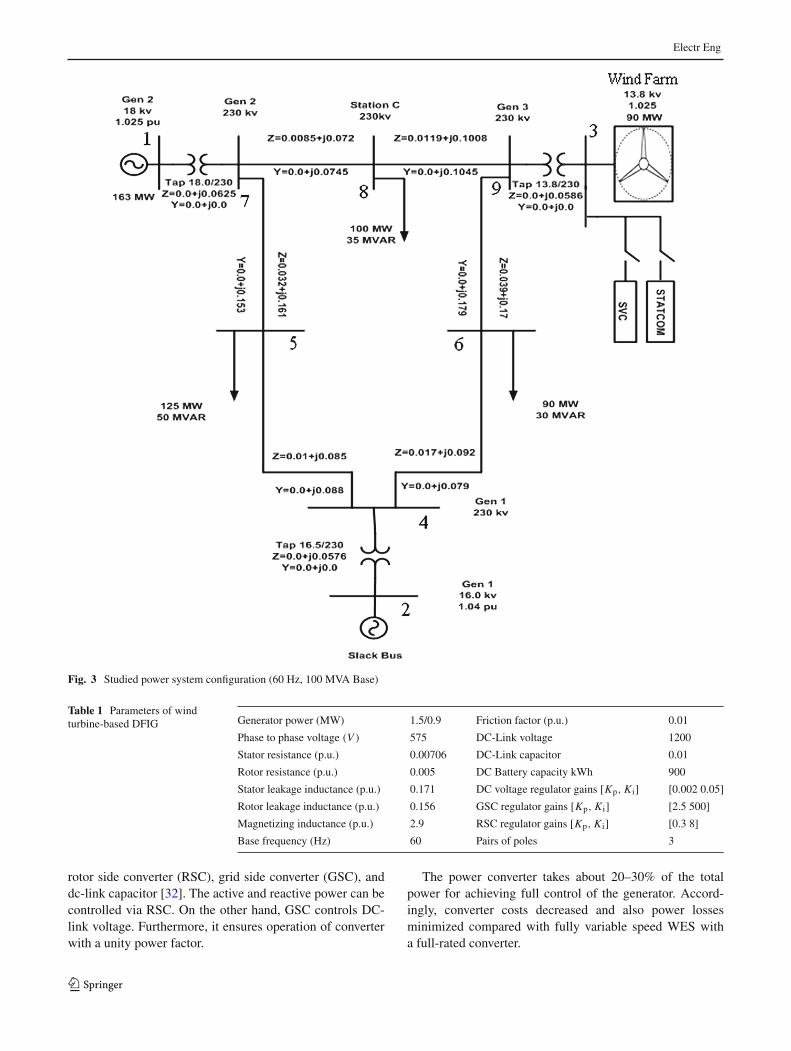
The dynamic time response of voltage, current, active,and reactive power of generator 1 is shown in Fig. 13. Onecan be noted that the system is unstable for a short periodbecause the fault is far away from this bus. The systemusing FACTs devices reaches steady state within 50%of time
Fig. 10 MATLAB/Simulink model of STATCOM-Based FLC
123

Electr Eng
Fig. 11 Simulink model of overall studied system
1.00 1.10 1.20 1.30 1.40
0
0.1
0.2
0.3
Time (sec)
SV
C re
activ
e po
wer
1.00 1.10 1.20 1.30 1.40
-0.1
0
0.1
0.2
0.3
0.4
Time (sec)
STA
TCO
M re
activ
e po
wer
1.00 1.10 1.20 1.30 1.40
-0.2
0
0.2
0.4
Time (sec)
SV
C s
usce
ptan
ce
1.00 1.10 1.20 1.30 1.40-0.4
-0.2
0
0.2
0.4
Time (sec)
STA
TCO
M Iq
Fig. 12 Dynamic time response of SVC and STATCOM reactive power
123
Electr Eng
1.00 1.05 1.1 1.15
0.2
0.4
0.6
0.8
1
Time (sec)
Vol
tage
(pu)
1.00 1.10 1.20 1.30 1.40
0.8
1
1.2
1.4
Time (sec)
Cur
rent
(pu)
no FACTsSVC FLCSTATCOM FLC
1.00 1.10 1.20 1.30 1.40
0.20.40.60.8
11.21.4
Time (sec)
Act
ive
Pow
er(p
u)
1.00 1.10 1.20 1.30 1.40-0.5
0
0.5
Time (sec)
Rea
ctiv
e P
ower
(pu)
no FACTsSVC FLCSTATCOM FLC
no FACTsSVC FLCSTATCOM FLC
no FACTsSVC FLCSTATCOM FLC
Fig. 13 Dynamic time response of voltage, current, active and reactive power of generator 1
1.00 1.10 1.20 1.30 1.40
0.4
0.6
0.8
1
1.2
Time (sec)
Vol
tage
(pu)
no FACTsSVC FLCSTATCOM FLC
1.00 1.10 1.20 1.30 1.40
0.7
0.8
0.9
1
1.1
1.2
Time (sec)
Cur
rent
(pu)
no FACTsSVC FLCSTATCOM FLC
1.00 1.10 1.20 1.30 1.40-1.4
-1.2
-1
-0.8
-0.6
-0.4
-0.2
Time (sec)
Act
ive
Pow
er(p
u)
no FACTsSVC FLCSTATCOM FLC
1.00 1.10 1.20 1.30 1.40
-0.5
0
0.5
Time (sec)
Rea
ctiv
e P
ower
(pu)
no FACTsSVC FLCSTATCOM FLC
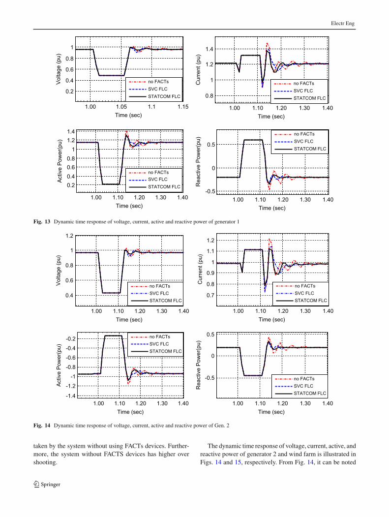
Fig. 14 Dynamic time response of voltage, current, active and reactive power of Gen. 2
taken by the system without using FACTs devices. Further-more, the system without FACTS devices has higher overshooting.
The dynamic time response of voltage, current, active, andreactive power of generator 2 and wind farm is illustrated inFigs. 14 and 15, respectively. From Fig. 14, it can be noted
123

Electr Eng
1.00 1.10 1.20 1.30 1.400
0.5
1
Time (sec)
Vol
tage
(pu)
no FACTsSVC FLCSTATCOM FLC
1.00 1.10 1.20 1.30 1.400
0.5
1
1.5
2
Time (sec)
Cur
rent
(pu)
no FACTsSVC FLCSTATCOM FLC
1.00 1.10 1.20 1.30 1.40
0
0.5
1
Time (sec)
Act
ive
Pow
er(p
u)
no FACTsSVC FLCSTATCOM FLC
1.00 1.10 1.20 1.30 1.40
-0.2
0
0.2
0.4
0.6
0.8
Time (sec)
Rea
ctiv
e P
ower
(pu)
no FACTsSVC FLCSTATCOM FLC
Fig. 15 Dynamic time response of voltage, current, active and reactive power of wind farm
1.00 1.10 1.20 1.30 1.40
0.4
0.6
0.8
1
1.2
Time (sec)
Vol
tage
bus
6 (p
u)
1.00 1.10 1.20 1.30 1.40
0.4
0.6
0.8
1
1.2
Time (sec)
Vol
tage
bus
7 (p
u)
1.00 1.10 1.20 1.30 1.400.2
0.4
0.6
0.8
1
1.2
Time (sec)
Vol
tage
bus
8 (p
u)
1.00 1.10 1.20 1.30 1.40
0.2
0.4
0.6
0.8
1
1.2
Time (sec)
Vol
tage
bus
9 (p
u)
no FACTsSVC FLCSTATCOM FLC
no FACTsSVC FLCSTATCOM FLC
no FACTsSVC FLCSTATCOM FLC
no FACTsSVC FLCSTATCOM FLC
Fig. 16 Dynamic time response of voltage at Buses B6, B7, B8 and B9
that the system using FACTs devices reaches steady statequickly (0.09 s). The system without FACTs devices takeslonger time to be stable (0.15 s).
From Fig. 15, it can be concluded that STATCOM andSVC have better time response. They have lower over shoot-ing (9%) and the system without facts has higher over
123

Electr Eng
1.00 1.10 1.20 1.30 1.400.2
0.4
0.6
0.8
1
1.2
Time (sec)
Vol
tage
(pu)
1.00 1.10 1.20 1.30 1.40
1
1.2
1.4
1.6
X: 430Y: 1.228
Time (sec)
Cur
rent
(pu)
1.00 1.10 1.20 1.30 1.400
0.5
1
Time (sec)
Act
ive
Pow
er(p
u)
1.00 1.10 1.20 1.30 1.40
-0.4
-0.2
0
0.2
0.4
0.6
Time (sec)
Rea
ctiv
e P
ower
(pu)
no FACTs
SVC FLCSTATCOM FLC
no FACTs
SVC FLCSTATCOM FLC
no FACTs
SVC FLC
STATCOM FLC
no FACTs
SVC FLC
STATCOM FLC
Fig. 17 Dynamic time response of voltage, current, active and reactive power of generator 1
shooting (17%). Also the system without FACTs devicestakes too long time to be stable again (0.18 s) compared tosystem with SVC and STATCOM (0.07 s).
The dynamic time response of voltage of system BusesB6, B7, B8 and B9 is illustrated in Fig. 16. For the figure,it can found that the time response of all system Buses volt-age improved by FACTs devices. The system with FACTSdevices has smaller settling time and overshooting. Further-more, STATCOM provides better performance than SVC.
8.2 Fault located at bus 8
The dynamic time response of voltage, current, active, andreactive power of machine number one is illustrated inFig. 17.
From Fig. 17, one can note that the system is unstable fora short period because the fault is far away from this bus.The system using FACTs devices reaches steady state within(0.07 s) almost half of time taken by the systemwithout usingFACTs devices (0.12 s). Furthermore, the system withoutFACTS devices has higher over shooting (3%) compared tosystem with FACTs (1%). STATCOM provides much betterperformance than SVC. The dynamic time response of volt-age, current, active and reactive power of machine numbertwo is illustrated in Fig. 18. From Fig. 18, one can notedthat FACTs devices improve overall system characteristics;the system has smooth and fast response. It can be noted
that the system using FACTs devices reaches steady statequickly (0.08 s). The system without FACTs devices takeslonger time to be stable (0.15 s). Furthermore, the response ofthe system without FACTS devices is sharp with much moreripples. Also, it has higher over shooting (5%) compared tosystem with FACTs devices (1%).
Figure 19 displays the dynamic time response of voltage,current, active, and reactive power of WF. It can be con-cluded that STATCOM and SVC have better time response.They have lower over shooting (9%), and the system with-out FACTs has higher over shooting (16%). Also the systemwithout FACTs devices takes too long time to be stable again(0.16 s) compared to system with FACTs devices (0.09 s).
The dynamic time response of voltage of system BusesB6, B7, B8, and B9 is illustrated in Fig. 20. It can concludethat the time response of all system buses voltage improvedby FACTs devices. The system connected to FACTS deviceshas smaller settling time and overshooting.
8.3 Fault located at bus 9
A100-ms temporary three-phase short circuit is applied after1.0 s at Bus 9. Fig. 21 displays the dynamic time responseof voltage, current, active, and reactive power of generator1. From this figure, it can be noted that the system usingFACTs devices reaches steady state quickly (0.07 s). Thesystem without FACTs devices takes longer time to be stable
123

Electr Eng
1.00 1.10 1.20 1.30 1.40
0.2
0.4
0.6
0.8
1
Time (sec)
Vol
tage
(pu)
1.00 1.10 1.20 1.30 1.40
0.8
1
1.2
1.4
Time (sec)
Cur
rent
(pu)
1.00 1.10 1.20 1.30 1.40
-1
-0.5
0
Time (sec)
Act
ive
Pow
er(p
u)
1.00 1.10 1.20 1.30 1.40-0.4
-0.2
0
0.2
0.4
Time (sec)
Rea
ctiv
e P
ower
(pu)
no FACTsSVC FLCSTATCOM FLC
no FACTsSVC FLCSTATCOM FLC
no FACTsSVC FLCSTATCOM FLC
no FACTsSVC FLCSTATCOM FLC
Fig. 18 Dynamic time response of generator 2 parameters
1.00 1.10 1.20 1.30 1.40
0.2
0.4
0.6
0.8
1
1.2
Time (sec)
Vol
tage
(pu)
1.00 1.10 1.20 1.30 1.40
0
0.5
1
Time (sec)
Cur
rent
(pu)
1.00 1.10 1.20 1.30 1.40
-0.2
0
0.2
0.4
0.6
Time (sec)
Act
ive
Pow
er(p
u)
1.00 1.10 1.20 1.30 1.40
-0.2
0
0.2
0.4
0.6
0.8
Time (sec)
Rea
ctiv
e P
ower
(pu)
no FACTsSVC FLCSTATCOM FLC
no FACTsSVC FLCSTATCOM FLC
no FACTsSVC FLCSTATCOM FLC
no FACTsSVC FLCSTATCOM FLC
Fig. 19 Dynamic time response of WF parameters
(0.17 s). Also the over shooting value is higher for sys-tem without FACTS (4%) compared to system with FACTs(2%).
Figure 22 displays the dynamic time response of voltage,current, active, and reactive power of machine number two.It can be concluded that STATCOM and SVC have better
123

Electr Eng
1.00 1.10 1.20 1.30 1.400.2
0.4
0.6
0.8
1
1.2
Time (sec)
Vol
tage
bus
6 (p
u)
1.00 1.10 1.20 1.30 1.400
0.5
1
Time (sec)
Vol
tage
bus
7 (p
u)1.00 1.10 1.20 1.30 1.40
0
0.5
1
Time (sec)
Vol
tage
bus
8 (p
u)
1.00 1.10 1.20 1.30 1.400
0.5
1
Time (sec)V
olta
ge b
us9
(pu)
no FACTsSVC FLCSTATCOM FLC
no FACTsSVC FLCSTATCOM FLC
no FACTsSVC FLCSTATCOM FLC
no FACTsSVC FLCSTATCOM FLC
Fig. 20 Dynamic time response of voltage at Buses B6, B7, B8, and B9
1.00 1.10 1.20 1.30 1.400.4
0.6
0.8
1
Time (sec)
Vol
tage
(pu)
1.00 1.10 1.20 1.30 1.40
1
1.2
1.4
1.6
Time (sec)
Cur
rent
(pu)
1.00 1.10 1.20 1.30 1.40 1.000
0.5
1
Time (sec)
Act
ive
Pow
er(p
u)
1.00 1.10 1.20 1.30 1.40
-0.4
-0.2
0
0.2
0.4
0.6
Time (sec)
Rea
ctiv
e P
ower
(pu)
no FACTsSVC FLCSTATCOM FLC
no FACTsSVC FLCSTATCOM FLC
no FACTsSVC FLCSTATCOM FLC
no FACTsSVC FLCSTATCOM FLC
Fig. 21 Dynamic time response of generator 1 parameters
time response. They have lower over shooting (1%), and thesystem without facts has higher over shooting (4%). Alsothe system without FACTs devices takes too long time to
be stable again (0.15 s) compared to system with SVC andSTATCOM (0.08).
Figure 23 displays the dynamic time response of volt-age, current, active, and reactive power of machine number
123

Electr Eng
1.00 1.10 1.20 1.30 1.40
0.4
0.6
0.8
1
Time (sec)
Vol
tage
(pu)
1.00 1.10 1.20 1.30 1.40
0.8
1
1.2
Time (sec)
Cur
rent
(pu)
1.00 1.10 1.20 1.30 1.40
-1
-0.5
0
Time (sec)
Act
ive
Pow
er(p
u)
1.00 1.10 1.20 1.30 1.40
-0.4
-0.2
0
0.2
0.4
Time (sec)
Rea
ctiv
e P
ower
(pu)
no FACTsSVC FLCSTATCOM FLC
no FACTsSVC FLCSTATCOM FLC
no FACTsSVC FLCSTATCOM FLC
no FACTsSVC FLCSTATCOM FLC
Fig. 22 Dynamic time response of generator 2 parameters
1.00 1.10 1.20 1.30 1.40
0.2
0.4
0.6
0.8
1
1.2
Time (sec)
Vol
tage
(pu)
no FACTsSVC FLCSTATCOM FLC
1.00 1.10 1.20 1.30 1.40
0.5
1
1.5
Time (sec)
Cur
rent
(pu)
no FACTsSVC FLCSTATCOM FLC
1.00 1.10 1.20 1.30 1.40
-0.2
0
0.2
0.4
0.6
Time (sec)
Act
ive
Pow
er(p
u)
no FACTsSVC FLCSTATCOM FLC
1.00 1.10 1.20 1.30 1.40
0
0.5
1
Time (sec)
Rea
ctiv
e P
ower
(pu)
no FACTsSVC FLCSTATCOM FLC
Fig. 23 Dynamic time response of WF parameters
three. In this state, the effectiveness of FACTs device isvery clear because the fault is very close to WES. It canbe concluded that STATCOM and SVC have better time
response. They have lower over shooting (9%), and the sys-tem without FACTs has higher over shooting (17%). Alsothe system without FACTs devices takes too long time to be
123

Electr Eng
stable again (0.15 s) compared to systemwith FACTs devices(0.08 s).
9 Conclusion
In this paper, the performance of wind farm-based DFIGfed to WSCC multi-machine power system has been eval-uated. The studied system subjected to sever three lines toground fault at various locations. Such locations are selectedto be positioned at the connection point of wind farm withWSCC system, the second point is located near to windfarm, and the third one is sited far from wind farm. A Mam-dani’s type FLC has been employed for controlling SVCand STATCOM that connected at wind farm. A compari-son study between SVC and STATCOM has been carriedout. The results of comparison reveal that FLC has a bet-ter performance with less overshoot during transient faults.Both SVC and STATCOM supplied the power system withreactive power under fault condition. FLC controller pro-vides better damping oscillation with a reduced settling time,fast and smooth response under fault conditions. Moreover,both SVC and STATCOM provide rapid recovery of termi-nal voltage after fault clearance. Finally, it can be said thatSTATCOM provides better performance than SVC, espe-cially if such devices controlled via fractional-order-basedfuzzy logic control. The integration between FLC robustnessand the accuracy of fractional-order will enhance the over-all system performance in comparison with the conventionalones.
References
1. Mohamed A, Eltamaly MAM, Abdulrahman I Alolah (2015)Sizing and techno-economic analysis of stand-alone hybrid pho-tovoltaic/wind/diesel/battery power generation systems. J RenewSustain Energy 7(6):063128
2. Mohamed AM, Eltamaly AM, Alolah AI (2016) PSO-based smartgrid application for sizing and optimization of hybrid renewableenergy systems. PloS one 11(8):e0159702
3. Renewables 2016 Global Status Report http://www.ren21.net/status-of-renewables/global-status-report/
4. Laouer M, Mekkaoui A, Younes M (2014) STATCOM and capaci-tor banks in a fixed-speed wind farm. Energy Procedia 50:882–892
5. Yufei T et al (2014) Reactive power control of grid-connected windfarm based on adaptive dynamic programming. Neuro Comput125:125–133
6. Olamaei J et al (2012) Advanced control of FACTS devices forimproving power quality regarding to wind warms. Energy Proce-dia 14:298–303
7. Kamarposhti M, Alinezhad M (2010) Comparison of SVC andSTATCOM in static voltage stability margin enhancement. Int JElectr Electron Eng 4(5):323–328
8. Yao XU, LI F (2014) Adaptive PI control of STATCOM for voltageregulation. IEEE Trans Power Deliv 29(3):1002–1011
9. Li H, Zhao B, Yang C, Chen HW, Chen Z (2011) Analysis andestimation of transient stability for a grid-connected wind turbinewith induction generator. Renew Energy 36:1469–1476
10. Le Cuong D, Bollen Math HJ (2010) Ride-through of inductiongenerator based wind park with switched capacitor, SVC, or STAT-COM, IEEE Power and Energy Society General Meeting, pp. 1–7
11. Marta M, Suul J, Tore U (2008) Low voltage ride through of windfarms with cage generators: STATCOM versus SVC. IEEE TransPower Electron 23(3):1104–1117
12. Stiebler M (2012) PM synchronous generator with diode rectifierfor wind systems using FACTS compensators. In: Internationalsymposium on power electronics, electrical drives, automation andmotion (SPEEDAM), pp 1295–1300
13. Wessels C et al (2013) StatCom control at wind farms with fixed-speed induction generators under asymmetrical grid faults. IndElectron IEEE Trans 60(7):2864–2873
14. Akshaya M, Varma RK, Ravi S (2014) SSR Alleviation by STAT-COM in induction-generator-based wind farm connected to seriescompensated line. Sustain Energy IEEE Trans 5(3):947–957
15. Qi L, Langston J, Steurer M (2008) Applying a STATCOMfor stability improvement to an existing wind farm with fixed-speed induction generators. Power and Energy Society GeneralMeeting—Conversion andDelivery of Electrical Energy, 21st Cen-tury, IEEE, pp 1–6
16. Jahangir H et. al, (2009) Robust STATCOM control for theenhancement of fault ride-through capability of fixed speed windgenerators. Control Applications, (CCA) & Intelligent Control,(ISIC), IEEE, pp 1505–1510
17. Kachroo R, Dalvi HS (2012) Study of various types of faults withneuro fuzzy controlled SSSC and STATCOM in stabilization ofgrid connected wind generator. In: Fifth international conferenceon emerging trends in engineering and technology (ICETET), pp202–206
18. Tian G,Wang S, Liu G (2010) Power quality and transient stabilityimprovement of wind farm with fixed-speed induction generatorsusing a STATCOM. In: International conference on power systemtechnology (POWERCON), pp 1–6
19. Okedu KE (2010) A study of wind farm stabilization using DFIGor STATCOM considering grid requirements. J Eng Sci Technol3(1):200–209
20. SaxenaN,KumarA (2016)Reactive power control in decentralizedhybrid power systemwith STATCOMusing GA, ANN and ANFISmethods. Electr Power Energy Syst 83:175–187
21. Laouera M, Mekkaouia A, Younesb M (2014) STATCOM andcapacitor banks in a fixed-speed wind farm. Energy Procedia50:882–892
22. Ahsan S, Siddiqui AS (2016) Dynamic compensation of real andreactive power in wind farms using STATCOM. Perspect Sci8:519–521
23. Das P et al. A Comparative Study in Improvement of Voltage Secu-rity in A Multi-Bus Power System Using STATCOM and SVC.978-1-4673-0136-7/11/$26.00 ©2011 IEEE
24. Rostami M, Soleymani S, Mozafari B (2012) Improve the voltageprofile of grid connected induction generator under load varia-tion and symmetrical short circuit in the presence of SVC andSTATCOM. In: Proceedings of 17th conference on electrical powerdistribution networks (EPDC), Tehran, Iran, 2–3 May 2012
25. Cakir G, RadmanG (2013) Placement and performance analysis ofSTATCOM and SVC for damping oscillation. In: 3rd internationalconference on electric power and energy conversion systems,YildizTechnical University, Istanbul, Turkey, October 2–4
26. Pereira R et al (2014) Comparative study of STATCOM andSVC performance on dynamic voltage collapse of an electricpower system with wind generation. IEEE Latin America Trans12(2):138–145
123

Electr Eng
27. Abd-Elazim SM, Ali ES (2016) Optimal location of STATCOM inmultimachine power system for increasing loadability by CuckooSearch algorithm. Electr Power Energy Syst 80:240–251
28. Abd-Elazim SM, Ali ES (2016) Imperialist competitive algorithmfor optimal STATCOM design in a multimachine power system.Electr Power Energy Syst 76:136–146
29. Wang Li, Truong D-N (2013) Stability enhancement of DFIG-based offshore wind farm fed to a multi-machine system usinga STATCOM. IEEE Trans Power Syst 28(3):2882–2889
30. Mohanty KB, Pati S (2016) Fuzzy logic controller based STAT-COM for voltage profile improvement in a micro-grid. In: AnnualIEEE conference in systems (SysCon), pp 1–6
31. Mondal D, Chakrabarti A, Sengupta A (2010) Selection of opti-mum location of power system stabilizer in a multimachine powersystem. J Electr Electron Eng Res 2(1):1–13
32. TangY, Ju P,HeH,QinC,WuF (2013)Optimized control ofDFIG-basedwind generation using sensitivity analysis and particle swarmoptimization. IEEE Trans Smart Grid 4(1):509–520
33. Narimani M, Rajiv K (2010) Application of static var compensator(SVC) with fuzzy controller for grid integration of wind farm. In:23rd Canadian Conference on Electrical and Computer Engineer-ing (CCECE). IEEE, pp 1–6
34. Bai Y, Wang D (2006) Fundamentals of fuzzy logic control–fuzzysets, fuzzy rules and defuzzifications. Advanced fuzzy logic tech-nologies in industrial applications. Springer, London
35. Shi J, KalamA, Shi P (2015) Improving power quality and stabilityof wind energy conversion system with fuzzy-controlled STAT-COM. Aust J Electr Electron Eng 12(3):183–193
36. Hasan N, Farooq S (2012) Dynamic performance analysis of DFIGbased wind farm STATCOM and SVC. Int J Emerg Technol AdvEng (IJETA) 2(7):461–469
37. Nadarajah M et al (2003) Comparison of PSS, SVC, and STAT-COM controllers for damping power system oscillations. PowerSyst IEEE Trans 18(2):786–792
38. Lo KL, KHAN L (2000) Fuzzy logic based SVC for power sys-tem transient stability enhancement. In: International conferenceon electric utility deregulation and restructuring and power tech-nologies, Proceedings. DRPT. IEEE, pp 453–458
39. SreekanthN, PavanKumarReddyN (2012) PI&Fuzzy logic basedcontrollers STATCOM for grid connectedwind generator. Int J EngRes Appl (IJERA) 2(5):617–623
40. Laouer M, Mekkaoui A, Younes M (2014) STATCOM and capaci-tor banks in a fixed-speed wind farm. Energy Procedia 50:882–892
41. Obulesu D, Kodad SF, Sankar Ram BV (2009) Novel developmentof a fuzzy control scheme with Upfc’s for damping of oscillationsin multi-machine power systems. Int J Rev Comput 1:25–40
42. Noueldeen O, Rihan M, Hasanin B (2011) Stability improvementof fixed speed induction generator wind farm using STATCOMduring different fault locations and durations. Ain Shams Eng J2(1):1–10
123