Embed Size (px)
Citation preview

A complete simulation
ecosystem - LS-DYNA
TRB First International Roadside Safety Conference Presented by Jason Wang (LSTC)

Silverado / Box-Beam Guardrail
Courtesy of: Steve Kan, Dhafer Marzougui (CCSA, George Mason University)

VOLVO XC90 GEN II Crash CAE model 2014
• CrachFEM materials
• Detailed HAZ welds
• Multiple airbags
• Rolling wheels
• New powertrain models
• New chassis models
• Steering mechanics from
wheel to steering wheel
• Total number of elements: 10 000 000+
• Number of CPU’s: 480
Courtesy of: VOLVO CAR CORPORATION

Outline
• Introduction
• Resources
– Dummies and Barriers
– LS-OPT/LS-TaSC
– Materials
– Element
formulations/Isogeometric
Analysis (IGA)
– Contacts
– User Interface
• Multiphysics solvers
– ALE
– Particle Methods/Meshfree
– Implicit analysis
– Frequency Domain Analysis
– ICFD
– Electro-Magnetic Solver
• Efficiency, Performance
• Summary

LS-PrePost
LS-DYNA
No additional license cost
USA
LS-OPT/LS-TaSC
Dummies & Barriers
Livermore Software Technology Corporation
(LSTC)
Founded by Dr. Hallquist in 1987

LS-DYNA Applications
Automotive Crash and safety
NVH & Durability
FSI
Aerospace Bird strike
Containment
Crash
Manufacturing Stamping
Forging
Welding
Consumer Products
Structural Earthquake safety
Concrete structures
Homeland security
Electronics Drop analysis
Package analysis
Thermal
Defense Weapons design
Blast and Penetration
Underwater Shock Analysis
Biosciences
Development costs are spread across many industries
Explicit/Implicit
Heat Transfer
ALE & Mesh Free i.e., EFG, SPH, Airbag Particle
User Interface Elements, Materials, Loads
Acoustics, Frequency
Response, Modal
Methods
Discrete Element Methods
Incompressible Fluids
CESE Compressible Fluids
Electromagnetics
Control Systems
Includes coupled Multi-Physics, Multi-Scale , and Multi-Stage in one Scalable Code
LS-DYNA - Current Capabilities

Multi-physics and Multi-stage Structure + Fluid + EM + Heat Transfer
Implicit + Explicit ….
Multi-scale Failure predictions, i.e., spot welds
Multi-formulations linear + nonlinear + peridynamics + …
The Neon crash model is courtesy of FHWA/NHTSA National Crash Analysis
Center
Single Model for Multiple Disciplines Manufacturing, Durability, NVH, Crash, FSI
LS-DYNA - One Code, One Model
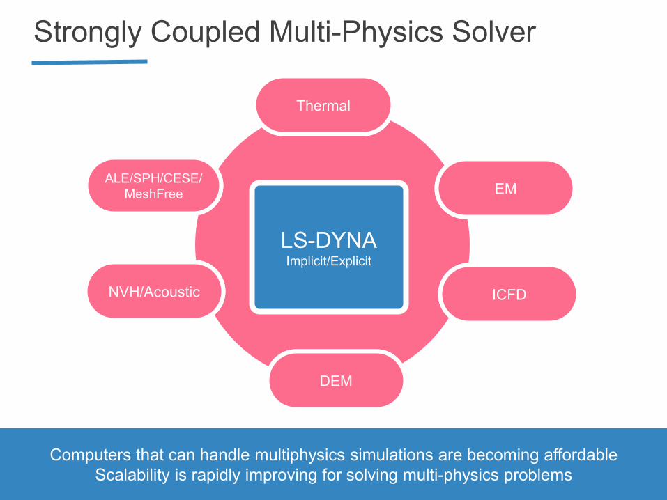
Strongly Coupled Multi-Physics Solver
ALE/SPH/CESE/
MeshFree
Thermal
EM
ICFD
DEM
NVH/Acoustic
Computers that can handle multiphysics simulations are becoming affordable
Scalability is rapidly improving for solving multi-physics problems
LS-DYNA Implicit/Explicit

Dummies and Barriers
• For licensed LS-DYNA users – No separate licensing from LS-DYNA.
• Continuous updates and support from LSTC and
distributors
• Companies may improve models and keep the
improvements proprietary
• Companies may redistribute their improved models
to their suppliers and subsidiaries for LS-DYNA
simulations

Released LSTC Dummy Models
Detailed Models FAST Models
HYBRID III 5th HYBRID III 5th
HYBRID III 50th HYBRID III 50th
HYBRID III 95th (scaled) HYBRID III 95th
SID IIs D SID IIs D
EuroSID 2 HYBRID III 5th Lower Body
EuroSID 2re HYBRID III 50th Lower Body
USSID HYBRID III 50th standing
HYBRID III 6-year-old THOR (alpha)
Free Motion Headform
Pedestrian Legforms

Improvements and Developments
Update in progress:
• EuroSID 2-re
• Hybrid III 50th
• Hybrid III 5th Female
• Thor FAST
New development:
• Hybrid III 3-year old
• WorldSID 50th
• Hybrid II

LSTC family of barriers
ECER95 shell
IIHS shell/solid
ODB shell/hybrid
214 shell/solid
AE-MDB shell
RCAR Barrier OMDB New PDB BARRIER
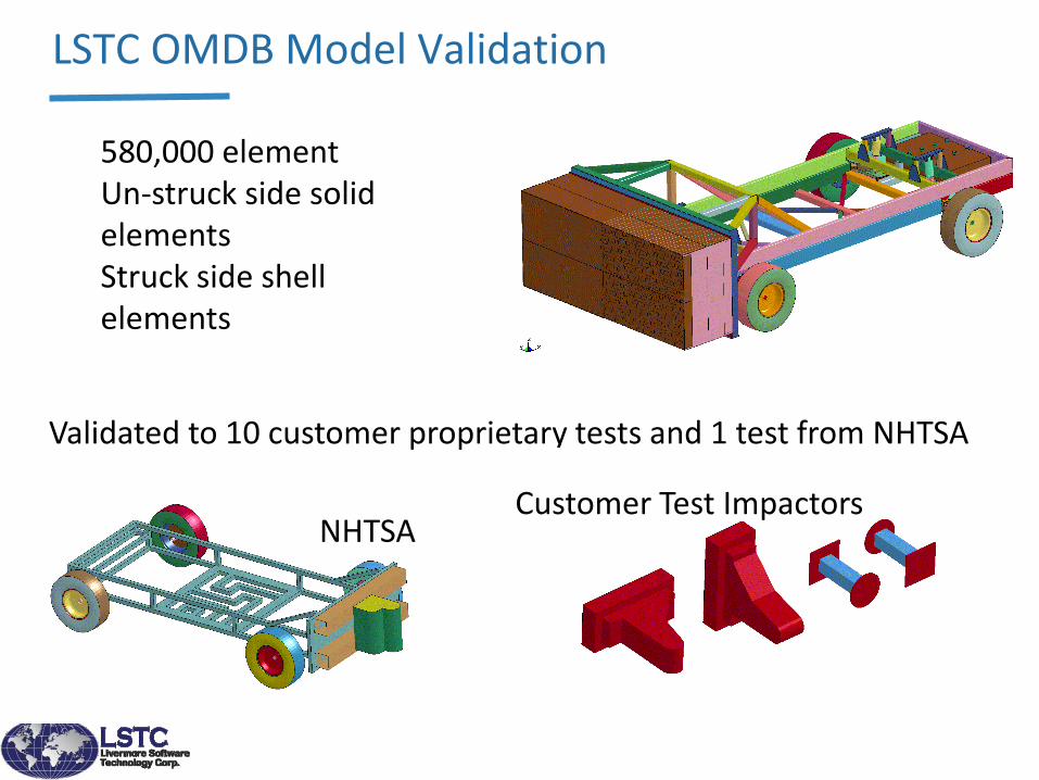
LSTC OMDB Model Validation
580,000 element Un-struck side solid elements Struck side shell elements
Validated to 10 customer proprietary tests and 1 test from NHTSA
NHTSA Customer Test Impactors

LSTC Dummy and Barrier Models
• LSTC is committed to the continued development and support of our released and future dummy and barrier models
• LSTC dummy and barrier models are available at no additional cost to current LS-DYNA customers
• All models are unencrypted and may be changed by customers
• Feedback is greatly appreciated but not required
For questions and feedback related to LSTC dummy and barrier models, please contact [email protected]
LS-OPT/LS-TaSC
Simulation-based Multidisciplinary Optimization.
• Seamlessly integrated with LS-DYNA
• Interfaces with a large number of pre/post-processors &
3rd party solvers.(ANSA, MetaPost, MATLAB, Excel,
NASTRAN)

LS-OPT
• The main analysis and optimization features of LS-OPT:
• Design Improvement and Optimization (MDO/MOO)
• System Identification
• Reliability-Based Optimization/Robust Design Optimization
• Outlier Analysis
• LS-DYNA job control • Network-based job scheduling and queuing
• Monitoring, logging, post-processing
• Secure Proxy Server (LSTCVM)

MDO: Vehicle Crash and Body Dynamics
6 Crash Modes + Body Dynamics Mode:
- approximately 3 million element models
Allen Sheldon, Ed Helwig (Honda R&D)

Tolerance Optimization
• Parameters
– 6 thicknesses bounded by tolerance: 𝒕 ∈ 𝑈[𝒕 (1 − 𝛿𝑡), 𝒕 (1 + 𝛿𝑡)]
– 1 relative tolerance (%) parameter: 𝛿𝑡
• Objective Functions:
– min𝒕 ,𝛿𝑡
Mass(𝒕 )
– max𝒕 ,𝛿𝑡
𝛿𝑡
• Performance constraints
– 𝑃 pulse1 𝒕 > 1 ≤ 휀
– 𝑃 pulse2 𝒕 > 1 ≤ 휀
– 𝑃 disp 𝒕 > 1 ≤ 휀
Total vehicle mass: 1800 kg Mass of optimized parts: 138 kg Maximum Mass Reduction: 23 kg Maximum Tolerance: 0.031 with corresponding mass reduction 18 kg
3,4
1,2 5
6
10 64
73
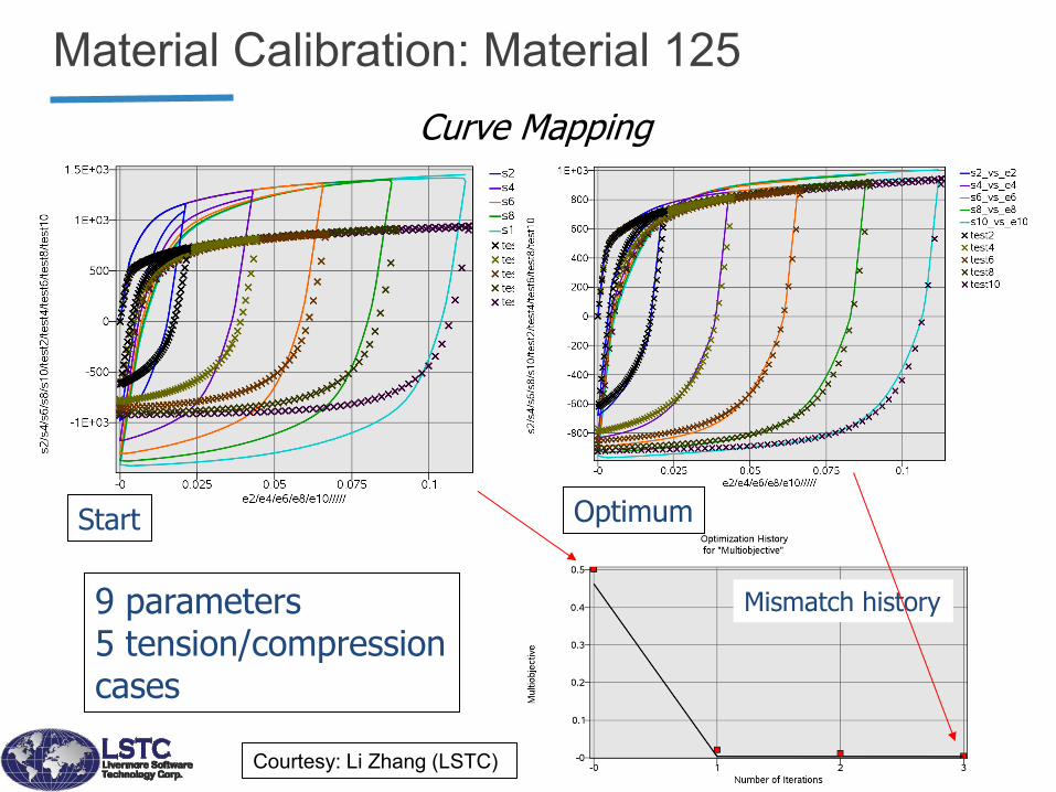
Material Calibration: Material 125
9 parameters 5 tension/compression cases
Mismatch history
Start Optimum
Courtesy: Li Zhang (LSTC)
Curve Mapping
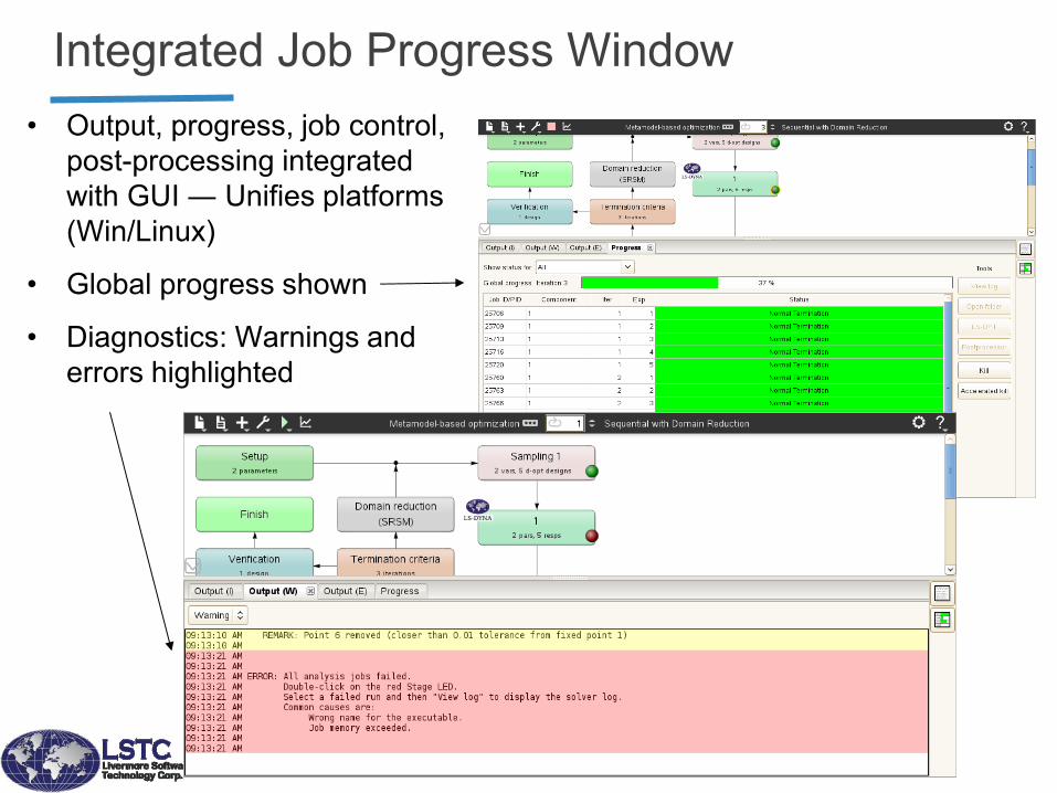
Integrated Job Progress Window
• Output, progress, job control,
post-processing integrated
with GUI ― Unifies platforms
(Win/Linux)
• Global progress shown
• Diagnostics: Warnings and
errors highlighted
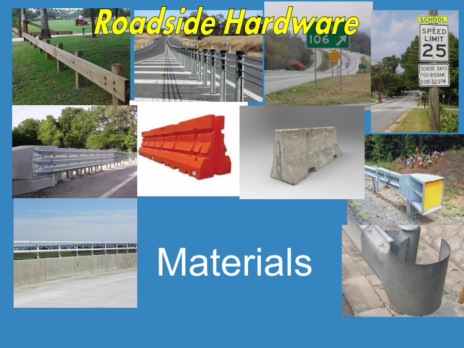
Materials

Geo-materials
• Geo-materials (Geologic Materials) include …
– Soil
– Rock
– Concrete
• Characteristics of Geo-materials
– Brittle in tension
– Pressure-dependent yield surface
– Can be highly compressible
• Macromechanical approach
• Mesomechanical approach - DEM

Concrete materials
MAT_# Material Description
72R3 *MAT_CONCRETE_DAMAGE_REL3 Karagozian & Case (K&C) Concrete
Model Release 3
78 *MAT_SOIL_CONCRETE Concrete and soil
84/85 *MAT_WINFRITH_CONCRETE Winfrith Concrete Model
159 *MAT_CSCM Continuous Surface Cap Model
272 *MAT_RHT RHT Concrete Model. An advanced
concrete model based on work by
Riedel, Thoma, and Hiermaier
= + + +
concrete aggregate
(>1mm)
sand
(<1mm)
pores mortar
Rebar

Other materials
• Foam Materials
• Hyperelastic Materials
• Polymer Materials
• Wood
• Biological materials
• Fabrics
• Glass and Ceramics
• ~300 material models
A great location to find out the existing efforts
http://www.dynalook.com

Element Formulations/
Isogeometric Analysis(IGA)
Courtesy of: Steve Kan, Dhafer Marzougui (CCSA, George Mason University)

Element Types in LS-DYNA®
• Point elements (mass, inertia)
• Discrete elements (springs, dampers)
• Beams
• Solids (2D and 3D, Lagrangian, Eulerian, ALE)
• Shells
• Thick Shells (8 noded)
• Seatbelts (and related components)
• EFG and SPH (meshless)
• Discrete, rigid spheres

27-node Solid Element
• Solid Formulation 24
• Accurate for large deformation, severe distortion
• Selective reduced integration to alleviate volumetric locking
• Excellent behavior in bending, one element is used over plate thickness
• Support *ELEMENT_SOLID_H8TOH27
• Under development 20, 64 node solid elements
27-node Hexahedron 21-node Pentahedron 19-node Pyramid 15-node Tetrahedral

4mm 2mm 1mm
Contact Force
Internal energy Relative coarse mesh can get converged results
Elform2 fine 27 node coarse 27 node fine
1 1.35 28
27-node Solid Element One layer element over thickness direction

Isogeometric Analysis (IGA)
• Element technology:
– T-spline input
– Trimmed NURBS patches
– Solid NURBS elements
– Mass scaling
• Boundary conditions:
– Tied edge-to-edge and edge-to-surface contact
– Nodes-to-surface
– Penalty-based boundary conditions
– Pressure loading
• Integration with other analysis capabilities:
– Fluid-structure interaction
– Frequency response analysis

regular NURBS-patch
trimmed NURBS
4 regular NURBS-patches
Control Points
Control Net
trimming
curve - standard in CAD
NURBS Meshes

*ELEMENT_SHELL_NURBS_PATCH
Standard
Shell-Elements
Trimmed
NURBS displacement
displacement
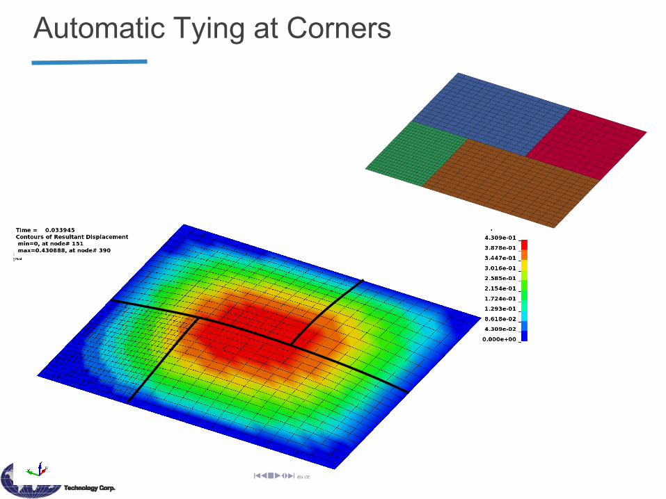
Automatic Tying at Corners

Combined FEA + IGA
Talk 6.2 Current Status of LS-DYNA® Iso-geometric Analysis in Crash Simulation Y. Chen, S-P. Lin, O. Faruque, J. Alanoly, M. El-Essawi, R. Baskaran

Contacts Allows unmerged Lagrangian elements to interact with each other • Parts that impact/push/slide/rub against each other
• Parts that should be tied together

Contacts
– Nodes/Segments based, Soft=0/1
– Segments/Segments based, Soft=2, Mortar
Nodes
Segments
Segments
Segments

Mortar Contact for Lagrangian/Classical FEM
• M.A.Puso and T.A.Laursen, A mortar segment-to-segment contact method for large deformation solid mechanics, Comput. Methods Appl. Mech. Engrg. 193 (2004)
• Goal to make it simple and universal with minimal options – Additional CPU time for increased accuracy
• Features – Segment to Segment with Accurate Contact Stress Integration
– Physical Geometry Contact
• Flat edges on shells
• Beams are cylinders with flat ends
• Couples to rotations for beams to exert moments
• Contact with sharp edges on solids and thick shells
– Friction
• Table, part and dynamic friction
• Wear prediction
• Ongoing improvements – High Order Element support
– Bucket sort frequency

Mortar Contact - Solids
SOFT=0 /1 SOFT=2 MORTAR
Mortar contact creates internal contact segments to deal with edges
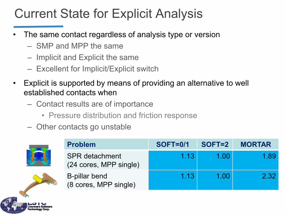
Current State for Explicit Analysis
• The same contact regardless of analysis type or version
– SMP and MPP the same
– Implicit and Explicit the same
– Excellent for Implicit/Explicit switch
• Explicit is supported by means of providing an alternative to well
established contacts when
– Contact results are of importance
• Pressure distribution and friction response
– Other contacts go unstable
Problem SOFT=0/1 SOFT=2 MORTAR
SPR detachment
(24 cores, MPP single)
1.13 1.00 1.89
B-pillar bend
(8 cores, MPP single)
1.13 1.00 2.32

Explicit Examples
Jensen et al, ”Broad-Spectrum Stress and Vibration Analysis of Large Composite Container”

User Interface
Provide an open interface for user to communicate with the
ecosystem. Accept user defined
• Loading
• Material model
• Element formulation
• Conatct
• External solver
• 3rd party libraries

*CONTACT_AUTOMATIC_..._TIEBREAK_USER
• User-defined interface for tiebreak contact
• Alternative models can be implemented
• Available for SMP, MPP and HYBRID
subroutine utb101(sig_n,sig_t,disp_n,disp_t,vel_n,vel_t,cn,ct,
. uparm,uhis,idcon,idsn,idms,areasn,areams,time,dt2,ncycle,crv,
. nnpcrv,temp,ifail,ioffset)
c
c User subroutine for tiebreak contact: OPTION=101
c
c Purpose: To define normal and tangential stresses and possible failure
c in a contact with tiebreak connection
c
c Variables:
c
c sig_n,sig_t = normal and tangential stress (output)
c disp_n,disp_t = normal and tangential displacement (input)
c vel_n,vel_t = normal and tangential relative velocity (input)
c cn,ct = normal and tangential stiffness (input)
c uparm = user defined tiebreak parameters (input)
c uhis = user defined tiebreak history variables (input/output)
c ...
• 3rd Party usermat interface, CrachFEM, etc

Couple with external solver
Interface to transfer necessary data between ls-dyna and
user program to perform coupled analysis
LS-DYNA External solver
𝑋
𝐹

Deformation
FEM
Structures
Lagrange
Accurate, Robust/Fast
Contact
Mesh distortion
Negative volume
Element eroding
Euler
Very expansive
Interface reconstruction
Lagrange
Expansive
Contact
Choice of solvers

ALE • Support 1D, 2D and 3D and
mapping
• Coupling between FEM, SPH, DEM (Interface reconstruction)
• Thermal explicit/implicit coupling
• Multi-material supports
• Incompressible fluid
■ Applications Fluid-Structure Interaction(FSI)
Bottle dropping, Sloshing and Splashing
High Velocity Impact, Bird strike
Explosion, Underwater explosion, Soil
penetration
Shape charge
Fragmentation and Spallation of the solid

FSI – Hydroplaning
Three Zone Concept
B.J.Allbert, SAE 680140 (1968)
Bulk Zone
Thin Film Zone
Dry Zone
A
B
C
:
:
:
Travel direction
Contact area
A B C
Water Tire
Road
Courtesy of The Yokohama Tire Co Ltd.
The dynamic pressure of water lifts tires off the ground.
Complete loss of traction
Hydroplaning test at a proving ground

FSI – Hydroplaning
Beginning water front
Bottom view - Half cut-off tire Tire-to-road contact force
Loss traction
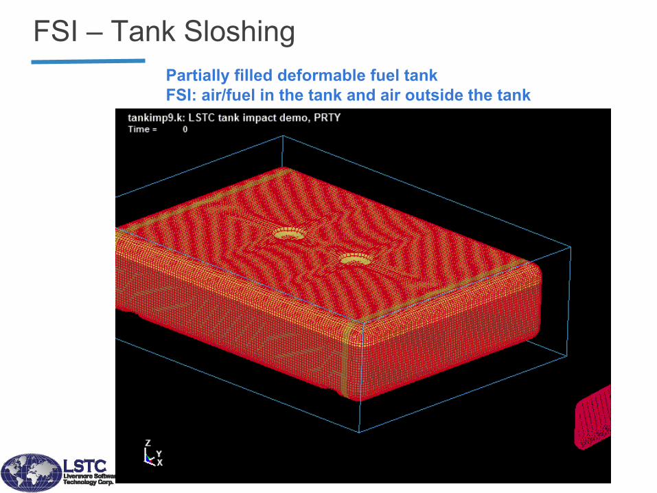
FSI – Tank Sloshing
Partially filled deformable fuel tank
FSI: air/fuel in the tank and air outside the tank

Particle/Meshfree Methods
55
Discrete
DEM (Discrete Element Method)
CPM (Particle Gas)
Particle Blast (DEM with CPM)
Continuum
Meshfree Collocation - SPH
Meshfree Galerkin – EFG, SPG,
MEFEM, Peridynamics

SPH - Introduction and Motivation
• Support 2D and 3D
• *Couple with FEM/DEM and different SPH parts (contact)
• SPH/Thermal explicit coupling
• More fluid capabilities
■ Applications
– Fluid-Structure Interaction, Bottle dropping.
– Sloshing and Splashing.
– Incompressible fluids.
– High Velocity Impact, Bird strike.
– Explosion, Underwater explosion, Soil
penetration.
– Forging and Extrusion, Metal cutting, Foam
packing.
– Fragmentation and Spallation of the solid.

SPH Enhancements
[1] Janosi, I. M., Jan, D., Szabo, K. G. and Tel, Tamas. “Turbulent drag reduction in dam-
break flows”. Experiments in Fluids, 37: 219-229, (2004).
Experiment [1] ICFD (Implicit) SPH (Explicit)
Murnaghan Equation of State Weakly compressible formulation to numerically reduce the sound speed, and
consequently increase the time step size
Enforce low compressibility
Validation: 2D dambreak, free surface flow

SPH/FEM hybrid element
Solid elements eroded, substituted with
SPH elements with user defined material New SPH elements coupled with FEM element
through hybrid elements.
Hybrid elements generated automatically

Modelling gas under “ideal gas law” as a set of rigid particles in “random motion”.
CPM - Introduction and Motivation
1xp
2xp
ms10t
■ Based on Kinetic Molecular Theory (KMT)
■ Follow Maxwell-Boltzmann velocity
distribution
■ Provide a realistic airbag deployment
process
■ Overcome many FSI problems using
traditional CFD numerical methods
■ Perfect for airbag out of position (OOP)
study

CPM - Enhancement on internal vents
H. Ida, M. Aoki, M. Asaoka, K. Ohtani,"A Study of gas flow behavior in airbag deployment simulation",24th International Technical Conference on the Enhanced Safety of Vehicles(ESV). No. 15-0081, 2015.

CPM - Vent with internal structure
CPM helps to design more sophisticated airbag.

DEM - Introduction and Motivation
■ Granular Media
■ Numerical Simulations Help to Design
■ Storage
■ Silos
■ Piles
■ Transportation
■ Conveyor belts/ screws
■ Pumps
■ Processing
■ Sorting
■ Mixing/ Segregation
■ Filling
■ Hopper/ funnel flow [Wiese Förderelemente GmbH]

DEM - Introduction and Motivation
Normal Force Fn=-k ∆X + C vn Tangential Force Ft=min(μFn, ∫kvtdt + C vt ) ∆X is the particle overlap k is the spring constant vn and vt are the normal and tangential velocity C is the dashpot damping coefficient μ is the friction coefficient
foamed clay dry sand wet sand fresh concrete “water”

DEM General Features
• *DEFINE_DE_TO_SURFACE_COUPLING
• Non-reflecting B.C. used on the exterior boundaries of an analysis
model of an infinite domain
Without
NRBC
With
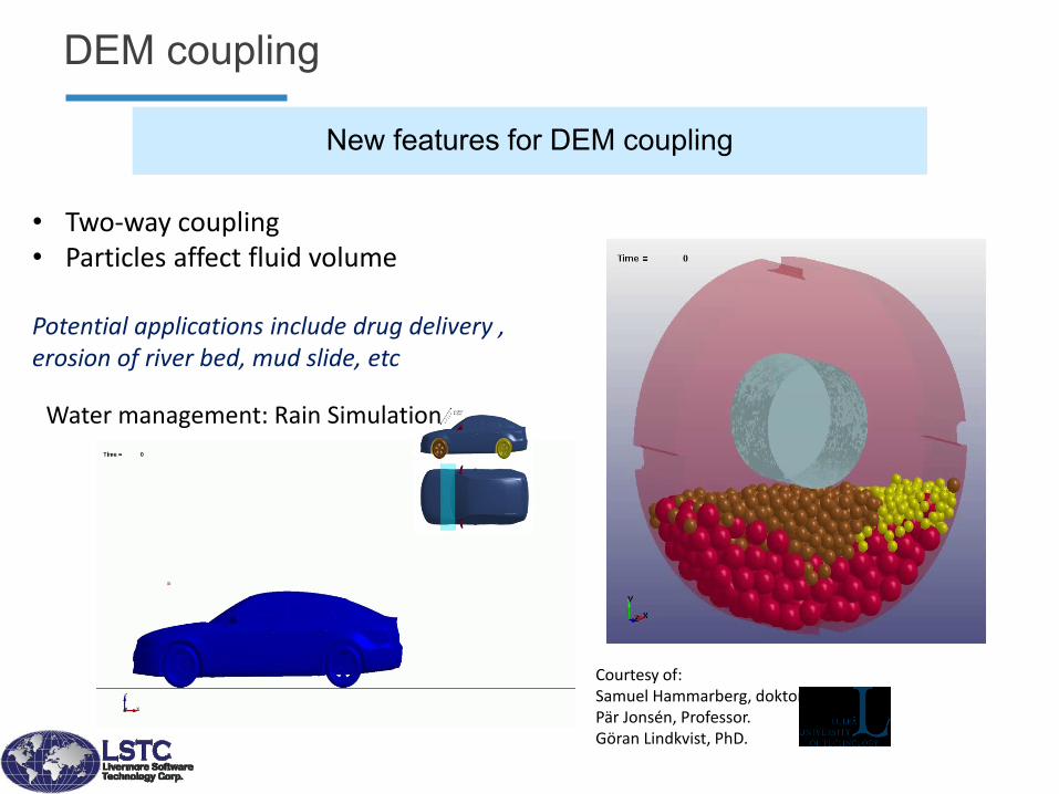
New features for DEM coupling
DEM coupling
• Two-way coupling • Particles affect fluid volume
Potential applications include drug delivery , erosion of river bed, mud slide, etc
Courtesy of: Samuel Hammarberg, doktorand. Pär Jonsén, Professor. Göran Lindkvist, PhD.
Water management: Rain Simulation

DEM – tire moving through wet/dry sand

DEM – Bonded DEM
Use bonds to form other shapes
• Particles are linked to their neighboring particles through bonds within a specified range.
• The properties of the bonds represent the complete mechanical behavior of Solid Mechanics.
• The bonds are independent from the DES model.
• They are calculated from Bulk Modulus and Shear Modulus of materials.
• Contact is disabled between bonded pair
• Contact is reactivated after bond broken
P1 P2 BOND 1<->2
P3
P6
P5
P4

DEM – Food sorting process

DEM – Bonded DEM
Displacement Damage

DEM for external load approximation
ICFD/DEM coupling

Efficiency, Performance Shared memory
• SMP (Shared Memory Parallel)
Start and base from serial code
Using OpenMP directives to split the tasks
Only run on SMP (single image) computers
Scalable up to ~16 CPUs
Clusters
• MPP (Message Passing Parallel)
Using the domain decomposition method
Using MPI for communications between sub-domains
Work on both SMP machines and clusters
Scalable >> 16 CPUs

0
2000
4000
6000
8000
10000
12000
14000
16000
1994 1996 1998 1999 2000 2002 2004 2006 2008 2014 2016
Model size for production crash analysis
Turn around time ~16 hours
BT shell
Fully integrated shell More sophisticated mat model
HW: Vector Vector+SMP SMP+Clusters Clusters Multicores
SW: Serial Serial+SMP SMP/MPI MPI+SMP
Smaller elements Solid spotweld cluster Multi-Physics
Mo
del S
ize (
x1000)
Transition from
SMP to MPP
Solid elements!
SMP only
MPP only

Moore’s Law
Do you notice cores/socket increase?
Do you see clockrate increase? Intel Code name Min. feature sz Rel. core/sck Clockrate Instruction
Bloomfield 45nm 2008 4 3.2 GHz SSE
Westmere 32nm 2010 6 2.4 GHz SSE
SandyBridge 32nm 2011 6 3.1 GHz AVX
Haswell 22nm 2013 18 2.5GHz AVX2
Skylake 14nm 2015 28 1.8GHz AVX512
Data collected from Wikipedia

Courtesy of: Steve Kan, Dhafer Marzougui (CCSA, George Mason University)
Road side safety simulations
• Contact Slide through a long guardrail
• Contact occurs in a small region
• Long simulation time
• Hard to scale with MPP
1
6
11
16
21
26
31
16 116 216 316 416CPU
Per
form
an
ceideal
Total
element
contact
rigidbody
Scaling of contact

Parallel Computing
CPU core counts
SMP MPP HYBRID
1 16 512
n nodes clusters 12 cores 2 sockets
Regular MPP n x 2 x 12 ranks
72 cores
72 MPP ranks
Hybrid MPP n x 2 ranks
72 cores
6 MPP ranks SMP
MPP
HYBRID
5,000+
SMP SMP
SMP SMP
SMP

New features and algorithms will be continuously implemented to handle new challenges and applications Electromagnetics,
Acoustics,
Compressible and incompressible fluids
Isogeometric shell & solid elements, isogeometric contact algorithms
Discrete elements
Peridynamics
Simulation based airbag folding and THUMS dummy positioning
Control systems and links to 3rd party control systems software
Composite material manufacturing
Battery response in crashworthiness simulations
Sparse solver developments for scalability to huge # of cores
Multi-scale capabilities are under development
Future

Capabilities Multi-physics and Multi-stage Structure + Fluid + EM + Heat Transfer
Implicit + Explicit ….
Multi-scale Accurate failure predictions
Multi-formulations linear + nonlinear + peridynamics + …
Our ultimate goal is to deliver one highly scalable software
to replace the multiplicity of software products currently
used for analysis in the engineering design process. Only
one model is needed and created.
Summary

Aerospace Working Group (awg.lstc.com)
Downloadable Input examples!
Tailor made function
Thank you!