Embed Size (px)
Citation preview
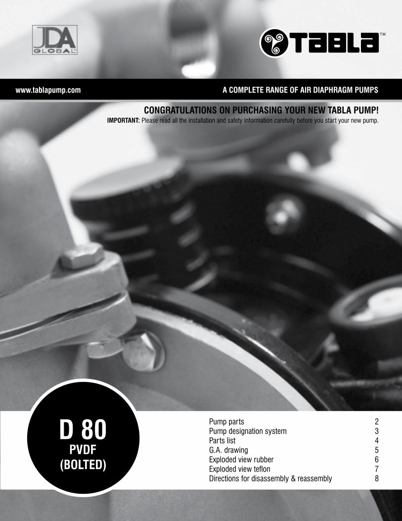
A COMPLETE RANGE OF AIR DIAPHRAGM PUMPSwww.tablapump.com
CONGRATULATIONS ON PURCHASING YOUR NEW TABLA PUMP!IMPORTANT: Please read all the installation and safety information carefully before you start your new pump.
Pump parts 2 Pump designation system 3Parts list 4G.A. drawing 5Exploded view rubber 6Exploded view teflon 7Directions for disassembly & reassembly 8
TM
D 80PVDF
(BOLTED)
TM
www.pricepumps.co.inwww.tablapump.com
2
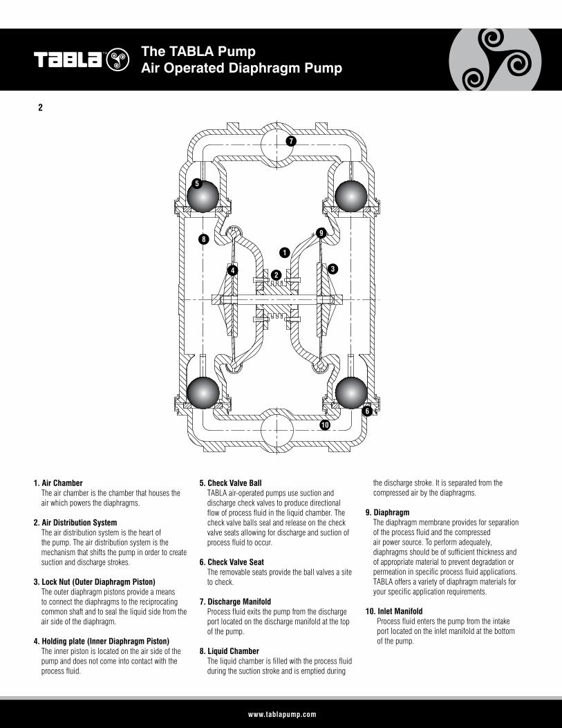
1. Air Chamber The air chamber is the chamber that houses the
air which powers the diaphragms.
2. Air Distribution System The air distribution system is the heart of
the pump. The air distribution system is the mechanism that shifts the pump in order to create suction and discharge strokes.
3. Lock Nut (Outer Diaphragm Piston) The outer diaphragm pistons provide a means
to connect the diaphragms to the reciprocating common shaft and to seal the liquid side from the air side of the diaphragm.
4. Holding plate (Inner Diaphragm Piston) The inner piston is located on the air side of the
pump and does not come into contact with the process fluid.
5. Check Valve Ball TABLA air-operated pumps use suction and
discharge check valves to produce directional flow of process fluid in the liquid chamber. The check valve balls seal and release on the check valve seats allowing for discharge and suction of process fluid to occur.
6. Check Valve Seat The removable seats provide the ball valves a site
to check.
7. Discharge Manifold Process fluid exits the pump from the discharge
port located on the discharge manifold at the top of the pump.
8. Liquid Chamber The liquid chamber is filled with the process fluid
during the suction stroke and is emptied during
the discharge stroke. It is separated from the compressed air by the diaphragms.
9. Diaphragm The diaphragm membrane provides for separation
of the process fluid and the compressed air power source. To perform adequately, diaphragms should be of sufficient thickness and of appropriate material to prevent degradation or permeation in specific process fluid applications. TABLA offers a variety of diaphragm materials for your specific application requirements.
10. Inlet Manifold Process fluid enters the pump from the intake
port located on the inlet manifold at the bottom of the pump.
1
32
10
4
9
5
8
7
The TABLA PumpAir Operated Diaphragm Pump
6

www.pricepumps.co.inwww.tablapump.com
TMThe TABLA PumpAir Operated Diaphragm Pump Pump Designation System
1AIR DISTRIBUTION SYSTEM
2 LIQUID PORT SIZE
3 WETTED PARTS 7,8
DIAPHRAGMS, VALVE BALLS
9 VALVE SEATS 11 CONNECTIONS
D Dura valve 40 40mm / 1 1/2” S Stainless Steel SN Santoprene™ (balls only)
S Stainless Steel N NPT
4 AIR CHAMBERS10
O-RING12 BOLTED
(OR CLAMPED)
A Aluminium TF TeflonB
Bolted
5 CENTER BLOCK
PPolypropylene (carbon-filled)
6 AIR VALVE
P Polypropylene
X / XX / XXXX / XX / XX / XXX / X / X1 2 3 4 5 6 7 8 9 10 11
1 AIR DISTRIBUTION SYSTEM 2 LIQUID PORT
SIZE 3 WETTED PARTS7,8
DIAPHRAGMS & VALVE BALLS 9 VALVE SEATS 11 CONNECTIONS
D Dura valve 15 15mm / 1/2” A Aluminium BN Buna - N / Nitrile A Aluminium N NPT
L Legacy valve 25 25mm / 1” S Stainless Steel ND Nordel / EPDM P Polypropylene B BSP
40 40mm / 1 1/2” P Polypropylene NE Neoprene S Stainless Steel 12 BOLTED(OR CLAMPED)
50 50mm / 2” K Kynar® / PVDF PU Polyurethane K Kynar® / PVDF B Bolted
80 80mm / 3” 4 AIR CHAMBERS SNSantoprene™ (balls only)
C Cast IronC Clamped
A Aluminium TFPTFE (with NEO back-up)
BN Buna - N / Nitrile
PPolypropylene (carbon-filled)
VT Viton/ FKMNE Neoprene
5 CENTER BLOCK ND Nordel / EPDM
A Aluminium VT Viton
PPolypropylene (carbon-filled)
SP Santoprene
6 AIR VALVE 10 O-RING
A Aluminium BN Buna - N / Nitrile
NE Neoprene
ND Nordel / EPDM
VT Viton
TF Teflon
12
D / 40 / SAPP / SN / TF / STF / N / B1 2 3 4 5 6 7 8 9 10 11 12
3

Par
ts L
ist
SR.NO DISCRIPTION QUANTITY TEFLON FITTED
PUMP OUTER PARTS
1 Liquid chamber 2 nos 80-5100-21
2 Suction bend 2 nos 80-5500-21
3 Discharge bend 2 nos 80-5400-21
4 Suc / Dis Tec 2 nos 80-5600-21
5 Valve balls 4 nos 80-1080-55
6 Valve seat 4 nos 80-1120-21
7 Ball cage 4 nos 80-5700-21
8 Seat gasket 4 nos 80-1200-53
9 Tee gasket 4 nos 80-1207-53
10 Inner diaphragm plate 2 nos 80-4501-01
11 Outer diaphragm plate 2 nos 80-4601-20
12 Diaphragm 2 nos 80-1010-55
13 Back up diaphragm 2 nos 80-1060-51
AIR CENTER PARTS
14 Center block 1 nos 80-3110-23
15 Center block “o” ring 4 nos 80-1300-51
16 Main shaft 1 nos 80-3811-59
17 Air chamber gasket 2 nos 80-3210-60
18 Air cover 2 nos 80-3620-01
19 Pilot bush ring 5 nos 80-3411-07
20 Pilot bushing “o” ring 6 nos 80-1312-51
21 Pilot bushing ring 2 nos 80-3412-07
22 Pilot shaft 1 nos 80-3410-03
23 Air valve body 1 nos 80-3710-23
24 Air valve 1 nos 80-2010-01
25 Piston Block Cap 2 nos 80-2310-01
26 Snap ring 2 nos 80-2410-61
27 Piston Block Cap “o” ring 2 nos 25-1205-53
28 Air valve w/o guide 1 nos 80-2510-01
29 Air valve cover gasket 1 nos 80-3212-60
30 Air valve gasket 1 nos 80-3211-60
ACCESSORIES
31 Muffler 1 nos 50-3500-23
32 Mounting pads 4 nos 80-8100-51
33 Air nipple 1 nos 50-8200-07
HARDWARE SET 80-6603-03
34 Air cover bolts(5 / 16 X 1”)
12 nos 40-6352-03
35 Chamber bolts(1/2” X 3 1/2”)
20 nos 80-6100-03
36 Suction discharge bolt 32 nos 25-6101-03
37 P.B. Holding bolts(1/4” X 4”)
6 nos 50-6300-03
38 Tee Bolt 32 nos 80-6056-03
MOC Neoprene Buna
Diaphragm 40-1010-55 40-1010-52
Balls 40-1080-55 40-1080-52
Tee o” ring N/A N/A
Seat o ring N/A N/A
Pump model 80-2503 80-2506

www.pricepumps.co.inwww.tablapump.com
TM
5
J.S.
Mumbai - 400 028. Tel. : 24440582 Fax. : 022 24440588 E-Mail :[email protected] :8, Gr. Flr.Hind Service Industrial Estate, Off Veer Savarkar Marg, Shivaji Park,
Factory : Plot No. 743, Phase II, G.I.D.C. Gundlav - 396 035, Dist. Valsad, PRICE PUMPSPVT. LTD.
PR CE
Gujarat State. Telefax : (02632) 236379, E-Mail :[email protected]
DIMENSIONS
• • • •
K c/c M c/c
•••
•N
BD
E
C
A
H
H
• • • • • • • •
50
95
• • • • • •
MOUNTING PAID
MOUNTING PAID DETAILS
58'' BSP
11
10
G. A. drawing without mounting pad and flange
D 80 PVDF Bolted

TM
www.pricepumps.co.inwww.tablapump.com

www.pricepumps.co.inwww.tablapump.com
TM
7
DETAIL - A
19 212022
1
2
3
4
5
7
86
9
10131211
14 16 15 1817
22 20
19
21
23
24272526
2829
30
31
32
33
35
34
35
35
36
34
37
43
38
Mumbai - 400 028. Tel. : 24453501 Fax. : 022 4440588 E-Mail :[email protected] :8, Gr. Flr.Hind Service Industrial Estate, Off Veer Savarkar Marg, Shivaji Park,
Factory : Plot No. 743, Phase II, G.I.D.C. Gundlav - 396 035, Dist. Valsad, PRICE PUMPSPVT. LTD. Gujarat State. Telefax : (02632) 236379, E-Mail :[email protected] view- TEFLON fitted
D 80 PVDF Bolted

TM
www.pricepumps.co.inwww.tablapump.com
Directions For Disassembly & Reassembly D 80 PVDF Bolted
8
STEP 2 STEP 5
STEP 3
Lift away the discharge manifold to expose the valve balls and seats.
Remove the discharge valve balls, O-rings and seats (Fig 4) from the liquid chambers and inspect for nicks, gouges, chemical attack or abrasive wear. Replace worn parts with genuine TABLA parts for reliable performance.
STEP 4 STEP 7STEP 1
Remove the discharge valve balls, O-rings and seats (Fig 7) from the liquid chambers and inspect for nicks, gouges, chemical attack or abrasive wear. Replace worn parts with genuine TABLA parts for reliable performance.
Before starting disassembly, mark a line from each liquid chamber to its corresponding air chamber. This line will assist in proper alignment during reassembly.
Utilizing a wrench, remove the bolts that fasten the discharge manifold to the liquid chambers.
Remove the bolts which fasten the suction manifold to the liquid chambers.
DISASSEMBLY
Lift suction manifold from liquid chambers and centre section to expose intake valve balls and seat. Inspect ball cage area of liquid chamber for excessive wear and damage.
STEP 6
CAUTION: Before any maintenance or repair is attempted, the compressed air line to the pump should be disconnected and all air pressure allowed to bleed from the pump. Disconnect all intake, discharge, and air lines. Drain the pump by turning it upside down and allowing any fluid to flow into a suitable container. Be aware of any hazardous effects of contact with your process fluid.
TOOLS REQUIRED:• Wrench• Allen Wrench• Adjustable Wrench• Adjustable Spanner• Vise equipped with soft jaws (such as plywood, plastic or other suitable material)

www.pricepumps.co.inwww.tablapump.com
TM
9
STEP 8
STEP 9
Remove one set of bolts, which secure one liquid chamber to the center section.
STEP 12
STEP 10
Lift liquid chamber away from center section to expose diaphragm and lock nut (outer piston).
Using an adjustable wrench, or by rotating the diaphragm by hand, remove the diaphragm assembly.
NOTE: Due to varying torque values, one of the following two situations may occur:
1) The lock nut (outer piston), diaphragm and holding plate (inner piston) remain attached to the shaft and the entire assembly can be removed from the center section (Fig 12).
2) The lock nut (outer piston), diaphragm and holding plate (inner piston) separate from the shaft which remains connected to the opposite side diaphragm assembly (Fig 13). Repeat disassembly instructions for the opposite liquid chamber. Inspect diaphragm assembly and shaft for signs of wear or chemical attack. Replace all worn parts with genuine TABLA parts for reliable performance.
To remove diaphragm assembly from shaft, secure shaft with soft jaws (a vise fitted with plywood or other suitable material) to ensure shaft is not nicked, scratched, or gouged. Using an adjustable wrench or by hand, remove diaphragm assembly from shaft. Inspect all parts for wear and replace with genuine TABLA parts if necessary.
REASSEMBLY
STEP 11
Upon performing applicable maintenance to the air distribution system, the pump can now be reassembled. Please refer to the disassembly instructions for photos and parts placement. To reassemble the pump, follow the disassembly instructions in reverse order. The air distribution system needs to be assembled first, then the diaphragms and finally the wetted parts. Please find the applicable torque specifications on this page. The following tips will assist in the assembly process.• Clean the inside of the center section shaft bushing to
ensure no damage is done to new seals.• Stainless bolts should be lubed to reduce the
possibility of seizing during tightening.• Ensure proper alignment on the sealing surfaces of
intake and discharge manifolds.• Liquid chambers are easier to attach when the
diaphragm is inverted. Prior to attaching the second water chamber, push diaphragm assembly so that it is as close as possible to the center section.
• PVDF pumps require Teflon® gasket kits for improved sealing. Gasket kits may be installed on other pumps where sealing is an issue.
MAXIMUM TORQUE SPECIFICATIONS
DESCRIPTION OF PART PLASTIC PUMPS
AIR VALVE 3.4m-N[30in.-lbs.]
LOCK NUT (OUTER PISTON) 51.5m-N[38ft.-lbs.]
SMALL CLAMP BAND 9.6m-N[85in.-lbs.]
NUT - BOLTS (Rubber Diaphragm) 18.6m-N[165in.-lbs.]
NUT - BOLTS (Teflon Diaphragm) 18.6m-N[165in.-lbs.]

TM
www.pricepumps.co.inwww.tablapump.com
Directions For Disassembly & Reassembly Air Distribution systemD 80 PVDF Bolted
10
Now check the centre block i.e. air valve with air cover Take out main shaft, replace If worn out or scored. Check shaft block bush ‘O’ rings, replace If worn out.
Remove the piston circlips, check piston block gasket and piston block cover.
Remove pilot shaft by unscrewing two nylock nuts if found damage replace them.
Remove piston block cap by help and holding bolts. Check the ‘O’ rings. Replace if worn out or damaged.
Remove the locknuts (outer piston) with the help of a Bench wice.
Remove the diaphragm & lock nut If diaphragm are damaged replace them (always replace both the diaphragm).
Remove the piston block from the shaft block by opening the 4 holding bolts.
DISASSEMBLY
TOOLS REQUIRED:• Adjustable Spanner• 1⁄4” Spanner• 5⁄16” Spanner• Circlip Plyer• Vise equipped with soft jaws (such as plywood, plastic or other suitable material)
STEP 1
STEP 2
STEP 3
STEP 4
STEP 5
STEP 6
STEP 7

www.pricepumps.co.inwww.tablapump.com
TM
11
STEP 12
Check the air covers and shaft block gaskets. If found damaged, replace them.
Remove the pilot bushes. Check the ‘O’ rings. Replace if worn out or damaged.
Pilot bushes with rings and ‘O’ rings.
STEP 9
Remove air cover if required. Change gasket if Required.
Remove the piston. Check Piston rings. Clean the piston with solvent.
ASSEMBLY
For assembly, follow the reverse procedure.
STEP 8
STEP 10
STEP 11

ww
w.s
ixof
usde
sign
.com
AVAILABLE MATERIALS OF CONSTRUCTION - PUMPSSuction/discharge size 1/2” (15mm) 1”(25mm) 11/2”(40mm) 2”(50mm) 3”(75mm)
B = Bolted C = Clamped B C B C B C B C B C
Polypropylene (PP) 3 3 3 3 3 3 3 3
Polyvinylidene Fluoride (PVDF) 3 3 3 3 3 3 3 3
Stainless Steel (SS) 3 3 3 3 3
Aluminium (AL) 3 3 3 3 3
Cast Iron (CI) 3 3 3 3 3
Please consult us for your requirements for Hastelloy C, Alloy 20 etc.
A COMPLETE RANGE OF AIR DIAPHRAGM PUMPS
ISO 9001 : 2008
ISO 14001 : 2004
www.tablapump.com
T8585-3
TM
JDA Global LLC | 1351 Park Avenue, Suite 104, Redlands, CA, USA 92373