Embed Size (px)
Citation preview
Bell Labs Technical Journal ◆ October–December 1998 63Copyright 1998. Lucent Technologies Inc. All rights reserved.
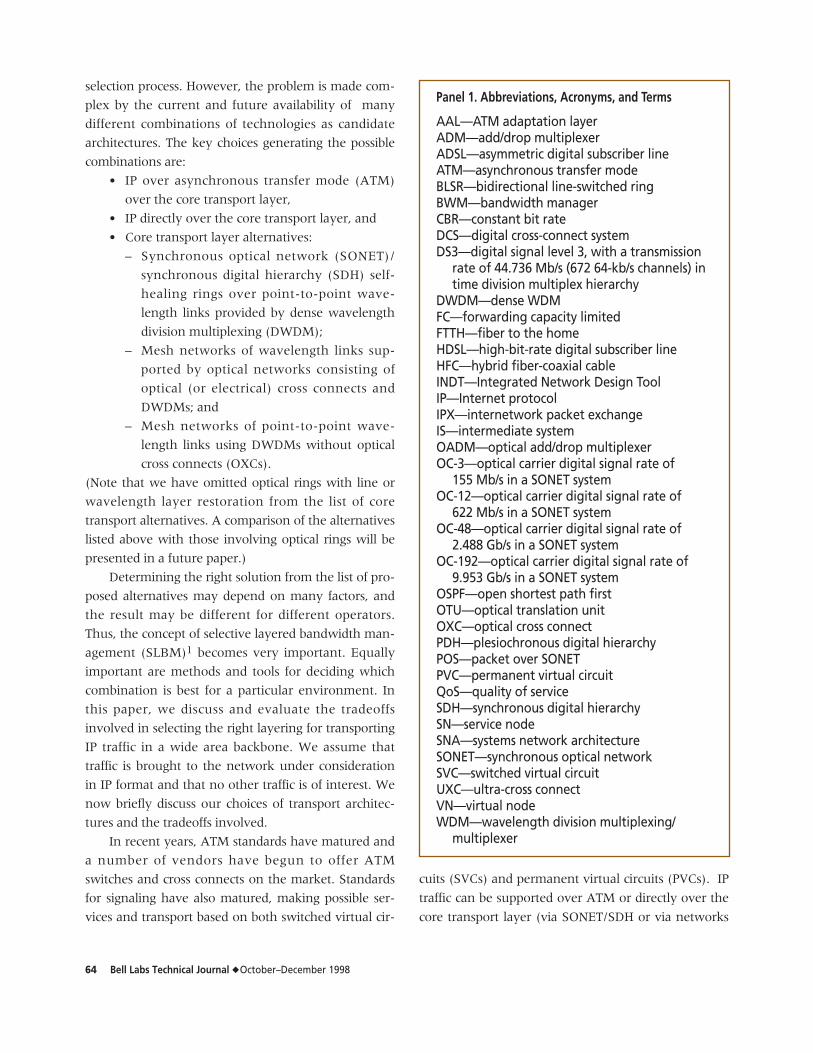
IntroductionThere has been a tremendous explosion in
Internet and corporate intranet traffic in recent years.
Service providers have been projecting growth rates
ranging from 50 to 300% per year for this traffic. This
growth is being fueled by various Web-based applica-
tions (for example, e-commerce and multimedia col-
laboration) and by the indirect impact of increased
computing power and storage capacity in the end sys-
tems. The advent of new services with increasing
intelligence and bandwidth needs will further add to
the traffic growth. The introduction of new access
technologies such as asymmetric digital subscriber line
(ADSL), high-bit-rate digital subscriber line (HDSL),
hybrid fiber-coaxial cable (HFC), and fiber to the
home (FTTH) will remove access bottlenecks and
impose an even faster growth of demand on the back-
bone network.
The selection of networking technologies and
architectures to be deployed to accommodate the
growth in Internet protocol (IP) traffic is a critical deci-
sion for network operators. Economics, performance,
reliability, and future proofing are key measures in the
♦ A Comparison of Next-GenerationIP-Centric Transport ArchitecturesBharat T. Doshi, Subrahmanyam Dravida, P. Harshavardhana,and M. Akber Qureshi
The popularity of the Internet and Internet protocol (IP)-based intranets is promisingenormous growth in data traffic originating from IP endpoints, prompting networkoperators to reconsider network architectures so that they can most effectivelyabsorb the projected growth. At the same time, new technologies are being intro-duced at a phenomenal pace, providing network operators with numerous and com-plex choices involving dense wavelength division multiplexing (DWDM), synchronousoptical networks (SONETs), packet over SONET (POS), packet over wavelength (POW),and asynchronous transfer mode (ATM). In this paper, we evaluate alternative trans-port architectures for carrying IP-based traffic using the projected traffic data, nodalconfiguration, and optical fiber connectivity of a realistic, national-scale IP back-bone. We compare the option of carrying IP directly versus IP over ATM for threetypes of transport architecture: SONET bidirectional line-switched rings (BLSRs); meshnetworks of optical (or electrical) cross connects; and DWDMs without underlyingoptical cross connects (OXCs)—that is, with one or more wavelength links betweeneach pair of IP switches. These options also include restoration choices. SONET BLSRsprovide fast restoration based on self-healing ring technology. OXCs provide fastrestoration for underlying mesh at the wavelength level. For point-to-point wave-length links, we consider service-level (IP and ATM) restoration. We compare theseoptions in terms of many network characteristics—port counts, circuit miles, wave-length miles, fiber miles, and overall cost—and consider all the critical constraintsand flexibilities for each choice.
64 Bell Labs Technical Journal ◆ October–December 1998
selection process. However, the problem is made com-
plex by the current and future availability of many
different combinations of technologies as candidate
architectures. The key choices generating the possible
combinations are:
• IP over asynchronous transfer mode (ATM)
over the core transport layer,
• IP directly over the core transport layer, and
• Core transport layer alternatives:
– Synchronous optical network (SONET)/
synchronous digital hierarchy (SDH) self-
healing rings over point-to-point wave-
length links provided by dense wavelength
division multiplexing (DWDM);
– Mesh networks of wavelength links sup-
ported by optical networks consisting of
optical (or electrical) cross connects and
DWDMs; and
– Mesh networks of point-to-point wave-
length links using DWDMs without optical
cross connects (OXCs).
(Note that we have omitted optical rings with line or
wavelength layer restoration from the list of core
transport alternatives. A comparison of the alternatives
listed above with those involving optical rings will be
presented in a future paper.)
Determining the right solution from the list of pro-
posed alternatives may depend on many factors, and
the result may be different for different operators.
Thus, the concept of selective layered bandwidth man-
agement (SLBM)1 becomes very important. Equally
important are methods and tools for deciding which
combination is best for a particular environment. In
this paper, we discuss and evaluate the tradeoffs
involved in selecting the right layering for transporting
IP traffic in a wide area backbone. We assume that
traffic is brought to the network under consideration
in IP format and that no other traffic is of interest. We
now briefly discuss our choices of transport architec-
tures and the tradeoffs involved.
In recent years, ATM standards have matured and
a number of vendors have begun to offer ATM
switches and cross connects on the market. Standards
for signaling have also matured, making possible ser-
vices and transport based on both switched virtual cir-
cuits (SVCs) and permanent virtual circuits (PVCs). IP
traffic can be supported over ATM or directly over the
core transport layer (via SONET/SDH or via networks
Panel 1. Abbreviations, Acronyms, and Terms
AAL—ATM adaptation layerADM—add/drop multiplexerADSL—asymmetric digital subscriber lineATM—asynchronous transfer modeBLSR—bidirectional line-switched ringBWM—bandwidth managerCBR—constant bit rateDCS—digital cross-connect systemDS3—digital signal level 3, with a transmission
rate of 44.736 Mb/s (672 64-kb/s channels) intime division multiplex hierarchy
DWDM—dense WDMFC—forwarding capacity limitedFTTH—fiber to the homeHDSL—high-bit-rate digital subscriber lineHFC—hybrid fiber-coaxial cableINDT—Integrated Network Design ToolIP—Internet protocolIPX—internetwork packet exchangeIS—intermediate systemOADM—optical add/drop multiplexerOC-3—optical carrier digital signal rate of
155 Mb/s in a SONET systemOC-12—optical carrier digital signal rate of
622 Mb/s in a SONET systemOC-48—optical carrier digital signal rate of
2.488 Gb/s in a SONET systemOC-192—optical carrier digital signal rate of
9.953 Gb/s in a SONET systemOSPF—open shortest path firstOTU—optical translation unitOXC—optical cross connectPDH—plesiochronous digital hierarchyPOS—packet over SONETPVC—permanent virtual circuitQoS—quality of serviceSDH—synchronous digital hierarchySN—service nodeSNA—systems network architectureSONET—synchronous optical networkSVC—switched virtual circuitUXC—ultra-cross connectVN—virtual nodeWDM—wavelength division multiplexing/
multiplexer
Bell Labs Technical Journal ◆ October–December 1998 65
of wavelength links). There are two principal advan-
tages of using ATM technology for carrying IP traffic.
First, ATM is a connection-oriented networking proto-
col that provides traffic engineering capabilities as well
as routing and grooming flexibilities. An ATM network
designer can allow multiple paths for IP traffic
between two edge routers by setting up multiple PVCs
and/or SVCs along different paths. Moreover,
resources can be reserved on these paths through pro-
visioning or signaling mechanisms. The network effi-
ciency can be improved by packing PVCs and SVCs on
multiple paths so that ports and links are better uti-
lized. Intermediate ATM switches provide grooming to
further improve the efficiency.
A second advantage of ATM is the ability to pro-
vide quality of service (QoS) differentiation. This abil-
ity is not important for IP traffic in the core backbone,
where the QoS differentiation capability of ATM is not
advantageous if the IP network outside the ATM cloud
does not provide QoS differentiation. If the IP network
does provide it (it will in the future), then the inter-
vening ATM layer is not beneficial. Of course, when
extended close to the end systems, the QoS differentia-
tion capability of ATM is an advantage, especially
because ATM can then integrate voice, private line,
and other traffic over the infrastructure designed for
carrying IP traffic. It may also provide transport for
high-quality IP telephony. Since we focus on the core
backbone, we ignore the differentiated QoS capability
of ATM. In other words, we assume that the service
provider has decided to bring IP traffic to the backbone
and is concerned with the selection of layering only in
the backbone.
Of course, having ATM between IP and the core
transport layer has its own disadvantages. ATM was
intended as a technology to integrate multiple services
and, therefore, was not optimized to transport a single
service such as IP. In particular, ATM imposes a band-
width overhead—commonly known as cell tax—of 20
to 25% for IP traffic. The cell tax is composed of two
parts: the ATM header and the ATM adaptation layer
(AAL) overhead (the wastage incurred in the last cell
due to segmentation of a data packet into cells). ATM
also introduces an additional layer of equipment that
must be deployed and managed. Thus, packet over
SONET (POS)2 interfaces are becoming important on
routers that directly transport IP traffic on the SONET
physical layer.
The choice between IP over ATM and IP directly
over the core transport layer thus involves tradeoffs
between the inefficiency caused by additional protocol
and equipment overhead and the efficiency generated
by the flexible routing and grooming provided by
ATM. While we focus exclusively on these tradeoffs,
other factors may also play a role in decision making.
These include embedded networks, the feasibility and
cost of building high-capacity ATM and IP switches,
other limitations on existing IP switches (for example,
forwarding capacity and traffic engineering features),
and the standards status of protocol innovations.
In addition to the IP versus IP over ATM choice at
higher layers, there are decisions to be made for the
core transport layers. The main questions regarding
these layers are:
• Should SONET/SDH be used in future net-
works?
• What role should be played by optical layer
networking?
Many factors affect these decisions. Certainly, a
SONET/SDH layer adds protocol overhead and equip-
ment cost. On the other hand, it provides a bandwidth
management function when point-to-point traffic may
not justify the whole wavelength. It also provides a
variety of management functions critical for smooth
operation of the network. Some or all of these func-
tions must be provided at the optical layer or at the
service layer before removal of the SONET/SDH layer
can be considered seriously. One such function is
restoration. The SONET/SDH layer provides fault
detection and restoration function in linear mesh or
ring-based networks. In particular, self-healing
SONET/SDH rings can restore service within 50 to
100 msec after any single failure. The emergence of
optical add/drop multiplexers (OADMs) and OXCs will
allow true optical networking layers to be deployed in
the future. They will also allow an arbitrary mesh or
ring topology at the physical layer. Advances in
restoration algorithms and architectures3 will allow
subsecond restoration at the optical layer in both ring
and mesh topologies. With these advances, we may
66 Bell Labs Technical Journal ◆ October–December 1998
have a true alternative to SONET/SDH ring restora-
tion. Restoration may also be performed at the IP or
ATM layer; it generally takes a longer time but may be
acceptable for many services. The time required for IP
or ATM layer restoration can be reduced significantly
by using aggregation techniques and precomputation
of restoration routes.
Thus, the key choices are presence or absence of
the SONET/SDH networking layer and, in the latter
case, optical or service layer restoration. For the
SONET/SDH layer, we use self-healing rings. For other
cases, we use the best mesh topology. The tradeoffs
among the available alternatives include equipment
costs, protocol overheads, restoration capacity needs,
facility requirements, and facility utilization. While dif-
ferences in restoration speeds may be important, we do
not consider restoration speed in our trade-off analysis.
The tradeoffs we consider between IP over ATM
and IP directly over the core transport layer reflect
some of the emerging enhancements in IP networks.
However, other advances will add more of the ATM-
like capabilities to IP switches and networks and will
affect the tradeoffs. First, most legacy routers use
software-based forwarding and are limited by the for-
warding capacity rather than by the aggregate link
capacities. In networks with such routers, there is a
significant penalty in using routers for grooming traffic
between other routers. Additionally, the links and
ports may have to be underutilized to account for the
limit on the forwarding capacity. Finally, this limit
may require more routers in a pure IP network. ATM
switches, on the other hand, always provide line-
speed switching, thus making the grooming function
essentially free. The emergence of IP switches with
wire-speed forwarding capability will make this dis-
tinction irrelevant. The more flexible routing and load-
balancing capabilities of ATM will still remain
important. The latter may be provided in IP networks
via multiprotocol label switching (MPLS) and explicit
route selection capabilities. While the QoS differentia-
tion capability of ATM may be an important advantage
if implemented as close as possible to the end sys-
tems—where integration of traffic with different QoS
requirements is an objective—even that picture is
changing. In particular, emerging IP switches (for
example, Lucent Technologies’ PacketStarTM IP
switch4) with wire-speed packet classification, sophisti-
cated QoS capability using hierarchical bandwidth
guarantees and active buffer management, and more
flexible routing are making IP switches comparable to
ATM switches in QoS management functions. Finally,
while the high end of IP switches may be more expen-
sive than corresponding ATM switches, the difference
is getting smaller.
While the ATM layer adds equipment and opera-
tions costs to the network, the additional cost depends
on how the various layers are implemented and oper-
ated. In particular, the move to build IP, ATM, and
SONET/SDH layers into a single piece of equipment
with flexible use of layers and integrated operations
minimizes both the capital and operations cost impact
of additional layers while providing the benefits of
flexible bandwidth management.
Since we focus on only one networking scenario
(wide area backbone carrying only IP traffic) and
assume some emerging capabilities in IP switches,
our results present only one dimension of a multi-
dimensional decision problem. Ongoing work cover-
ing the issues more exhaustively will be presented in
future papers.
Transport Architecture Choices for IP TrafficWe now describe the alternative architectures for
transporting IP traffic in a wide area backbone in some
detail. We begin with the architectures and tradeoffs
for IP over ATM and for IP directly over the core trans-
port layer.
IP over ATM Versus IP Directly over the Core Transport LayerIP provides connectionless service to direct traffic
through the network using addresses in the IP header
and routing table in each IP router. In particular, cur-
rent IP routers implement the following simple routing
concept: Given a destination address, a routing table
provides the next IP router address (and outgoing
port) corresponding to the shortest path through the
network. The shortest paths are based on the weights
assigned to the links in the network. State exchange
and route calculation protocols keep the routing tables
current by consistently updating them to reflect any
change in network behavior or topology. Two packets
Bell Labs Technical Journal ◆ October–December 1998 67
between the same source-destination pair will follow
different paths through the network if one is routed
before the update and the other is routed after the
update, assuming the update changed the shortest
path between the source-destination pair because of
changes in link weights. However, most IP networks
change link weights only in the event of failure. Thus,
the packets to a given destination typically follow the
same route in the absence of failure. Note that most IP
routers today route packets based on destination only
rather than on source-destination pair. Moreover, they
are limited by the aggregate forwarding capacity (in
packets per second) rather than by the aggregate link
speeds. Both have an impact on the efficiency of IP-
based networks.
The impact of the limitation on the forwarding
capacity is obvious. In particular, a router limited by
the forwarding capacity has a total capacity less than
the sum of the speeds of the links (ports) terminating
on it. This may create underutilization of long haul
links if there is no intervening layer to pack these
links. The limit on the forwarding capacity also limits
the scalability of router technology. The impact of rigid
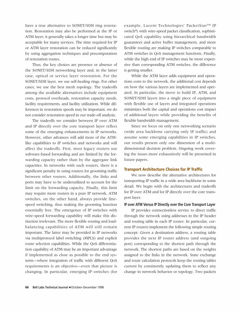
routing needs more explanation. Simple shortest-path
routing based on the destination address limits the
ability to pack bandwidth pipes and ports efficiently.
To understand this, consider the example illustrated in
Figure 1. Figure 1a depicts the bandwidth needed to
carry IP traffic between three source-destination node
pairs while providing acceptable service: 1.2 OC-12
between A and C, 0.6 OC-12 between A and B, and
0.7 OC-12 between B and C. This traffic can be packed
efficiently, requiring only a single OC-12 pipe between
each node pair, if 1.2 OC-12 traffic between source-
destination pair (A, C) can be split across two different
paths: (A → C) and (A → B → C), as shown in
Figure 1d. Suppose (A → C) is the only shortest path
between source-destination pair (A, C) for the current
link weights. In that case, IP routing protocols—for
example, OSPF and intermediate system (IS-IS)—do
not allow the splitting of traffic between (A → C) and
(A → B → C), thereby forcing inefficient packing.
C
A B
(a) Point-to-pointbandwidth needs
0.6-OC-12
1.2-OC-12 0.7-OC-12
C
B
(c) IP (OSPF)
2-OC-12
2-OC-12
C
A B
(b) IP (OSPF)
1-OC-12
2-OC-12 1-OC-12
C
A B
(d) Ideal
1-OC-12
1-OC-12 1-OC-12IP – Internet protocolOC – Optical carrierOSPF – Open shortest path first
A
Figure 1.Ideal routing and OSPF constraints.
68 Bell Labs Technical Journal ◆ October–December 1998
Figures 1b and 1c illustrate the two possible allocations
of OC-12 pipes between nodes satisfying the single
path constraint between a source-destination pair. Both
require more ports and links than in the ideal case.
Note that if the traffic between A and C needs
0.2 OC-12 instead of 1.2 OC-12, then all of this traffic
can be routed along path (A → B → C), eliminating
the link from node A to node C completely. Thus,
IP routing protocols allow efficient packing by elimi-
nating an entire link, but they do not allow splitting
the traffic to allow better packing.
ATM, on the other hand, provides connection-
oriented service and allows multiple paths between
the same source-destination pair whenever it is prof-
itable to do so. It also allows explicit routes that are dif-
ferent from the shortest path. Thus, ATM can provide
better packing of bandwidth pipes and ports. This is
one reason why ATM is a potential candidate to carry
IP traffic in the backbone in spite of the 20 to 25%
(average) cell tax to carry IP traffic over ATM.
Wherever IP pipes are already heavily utilized, carry-
ing IP on ATM is not justified because additional facili-
ties (and ports) may be needed to absorb the cell tax.
For the case in which IP pipes are lightly utilized, car-
rying IP over ATM may be more economical even
after considering the cost of ATM equipment. Of
course, there is then the tradeoff between using ATM
for finer bandwidth management and using
SONET/SDH equipment for lower granularity band-
width management.
The value of using ATM for carrying IP traffic thus
depends on the price of ATM equipment and the sav-
ings in cost, if any, that it may provide at the transport
layer for carrying fewer efficiently filled pipes. The for-
mer depends on how ATM and IP layers are imple-
mented. The latter depends on the facility granularity,
the cost of equipment in the core transport network to
provide that granularity, and the restoration strategy.
Note that the cost savings from packing transport facil-
ities depends on the transport technology and the
restoration strategy. As noted earlier, we do not con-
sider differences in the ability of IP and ATM to scale
the aggregate switching capacity and interface speeds
while continuing to provide wire-speed processing.
Architectures and Layering at the Core Transport LayerWe next describe the alternatives at the core
transport layer. Three possible architectures are
detailed in the following sections.
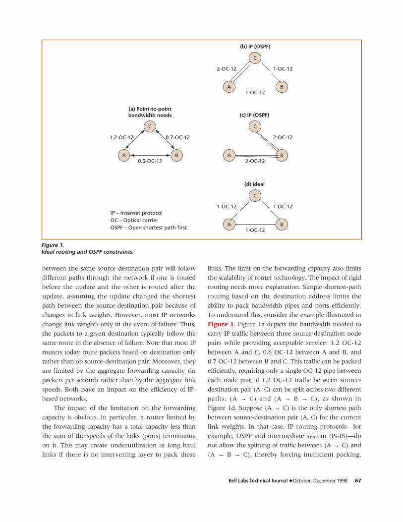
Architecture 1. The first alternative is a core trans-
port network consisting of an interconnected system of
SONET bidirectional line-switched rings (BLSRs) built
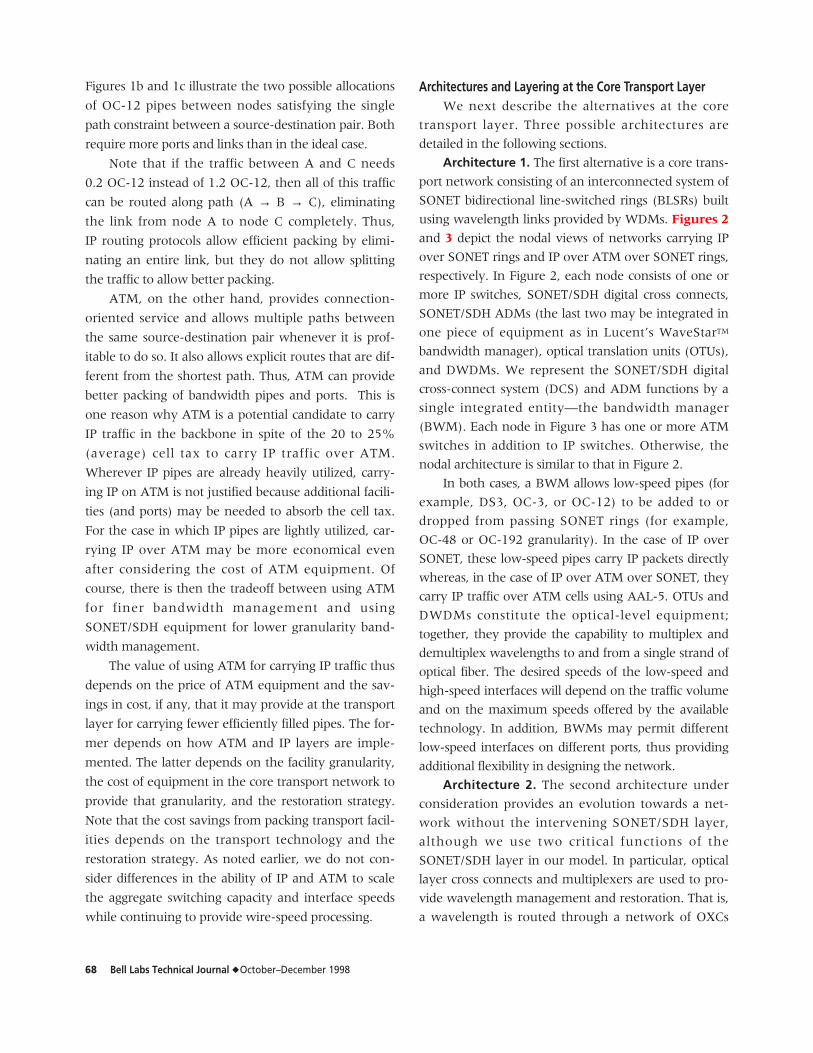
using wavelength links provided by WDMs. Figures 2
and 3 depict the nodal views of networks carrying IP
over SONET rings and IP over ATM over SONET rings,
respectively. In Figure 2, each node consists of one or
more IP switches, SONET/SDH digital cross connects,
SONET/SDH ADMs (the last two may be integrated in
one piece of equipment as in Lucent’s WaveStarTM
bandwidth manager), optical translation units (OTUs),
and DWDMs. We represent the SONET/SDH digital
cross-connect system (DCS) and ADM functions by a
single integrated entity—the bandwidth manager
(BWM). Each node in Figure 3 has one or more ATM
switches in addition to IP switches. Otherwise, the
nodal architecture is similar to that in Figure 2.
In both cases, a BWM allows low-speed pipes (for
example, DS3, OC-3, or OC-12) to be added to or
dropped from passing SONET rings (for example,
OC-48 or OC-192 granularity). In the case of IP over
SONET, these low-speed pipes carry IP packets directly
whereas, in the case of IP over ATM over SONET, they
carry IP traffic over ATM cells using AAL-5. OTUs and
DWDMs constitute the optical-level equipment;
together, they provide the capability to multiplex and
demultiplex wavelengths to and from a single strand of
optical fiber. The desired speeds of the low-speed and
high-speed interfaces will depend on the traffic volume
and on the maximum speeds offered by the available
technology. In addition, BWMs may permit different
low-speed interfaces on different ports, thus providing
additional flexibility in designing the network.
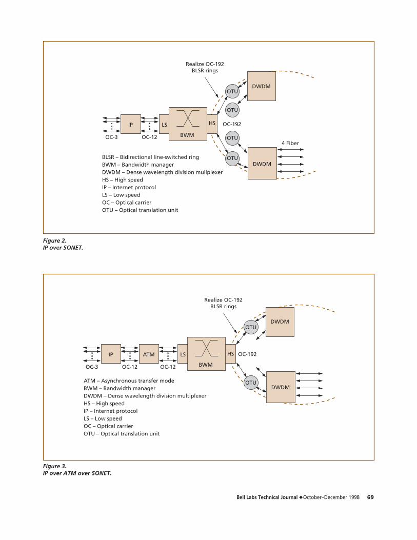
Architecture 2. The second architecture under
consideration provides an evolution towards a net-
work without the intervening SONET/SDH layer,
although we use two critical functions of the
SONET/SDH layer in our model. In particular, optical
layer cross connects and multiplexers are used to pro-
vide wavelength management and restoration. That is,
a wavelength is routed through a network of OXCs
Bell Labs Technical Journal ◆ October–December 1998 69
HS
BLSR – Bidirectional line-switched ringBWM – Bandwidth managerDWDM – Dense wavelength division muliplexerHS – High speedIP – Internet protocolLS – Low speedOC – Optical carrierOTU – Optical translation unit
IP LS
BWM
OTU
OTU
DWDM
DWDM
OC-192
4 Fiber
Realize OC-192BLSR rings
OC-3 OC-12 OTU
OTU
Figure 2.IP over SONET.
Figure 3.IP over ATM over SONET.
HS
ATM – Asynchronous transfer modeBWM – Bandwidth managerDWDM – Dense wavelength division multiplexerHS – High speedIP – Internet protocolLS – Low speedOC – Optical carrierOTU – Optical translation unit
IP LS
BWM
OTUDWDM
DWDMOTU
OC-192
Realize OC-192BLSR rings
OC-3 OC-12
ATM
OC-12
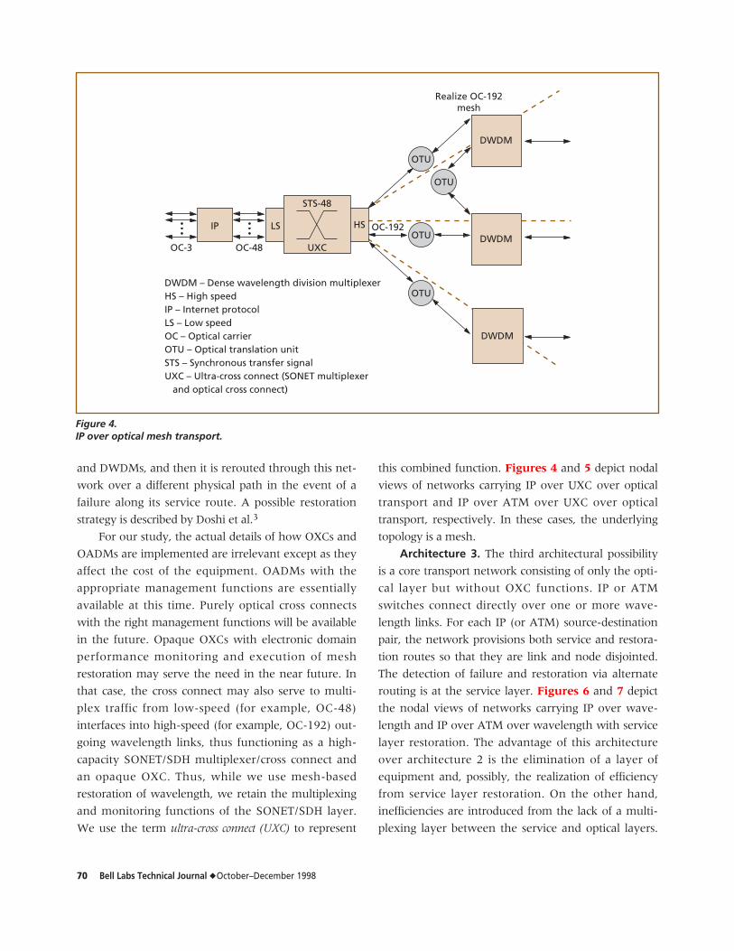
70 Bell Labs Technical Journal ◆ October–December 1998
and DWDMs, and then it is rerouted through this net-
work over a different physical path in the event of a
failure along its service route. A possible restoration
strategy is described by Doshi et al.3
For our study, the actual details of how OXCs and
OADMs are implemented are irrelevant except as they
affect the cost of the equipment. OADMs with the
appropriate management functions are essentially
available at this time. Purely optical cross connects
with the right management functions will be available
in the future. Opaque OXCs with electronic domain
performance monitoring and execution of mesh
restoration may serve the need in the near future. In
that case, the cross connect may also serve to multi-
plex traffic from low-speed (for example, OC-48)
interfaces into high-speed (for example, OC-192) out-
going wavelength links, thus functioning as a high-
capacity SONET/SDH multiplexer/cross connect and
an opaque OXC. Thus, while we use mesh-based
restoration of wavelength, we retain the multiplexing
and monitoring functions of the SONET/SDH layer.
We use the term ultra-cross connect (UXC) to represent
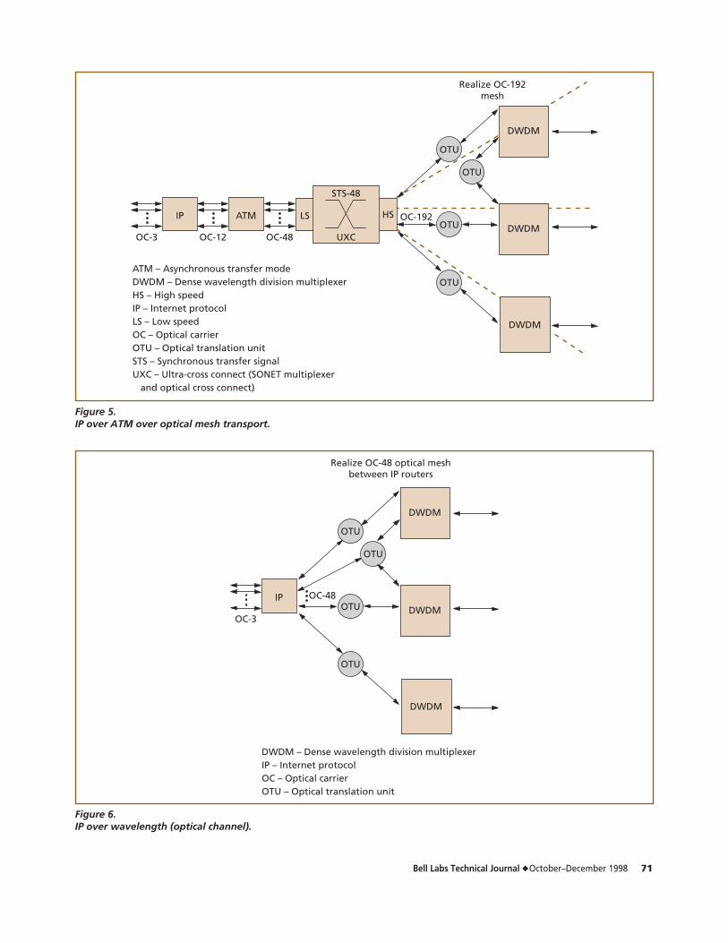
this combined function. Figures 4 and 5 depict nodal
views of networks carrying IP over UXC over optical
transport and IP over ATM over UXC over optical
transport, respectively. In these cases, the underlying
topology is a mesh.
Architecture 3. The third architectural possibility
is a core transport network consisting of only the opti-
cal layer but without OXC functions. IP or ATM
switches connect directly over one or more wave-
length links. For each IP (or ATM) source-destination
pair, the network provisions both service and restora-
tion routes so that they are link and node disjointed.
The detection of failure and restoration via alternate
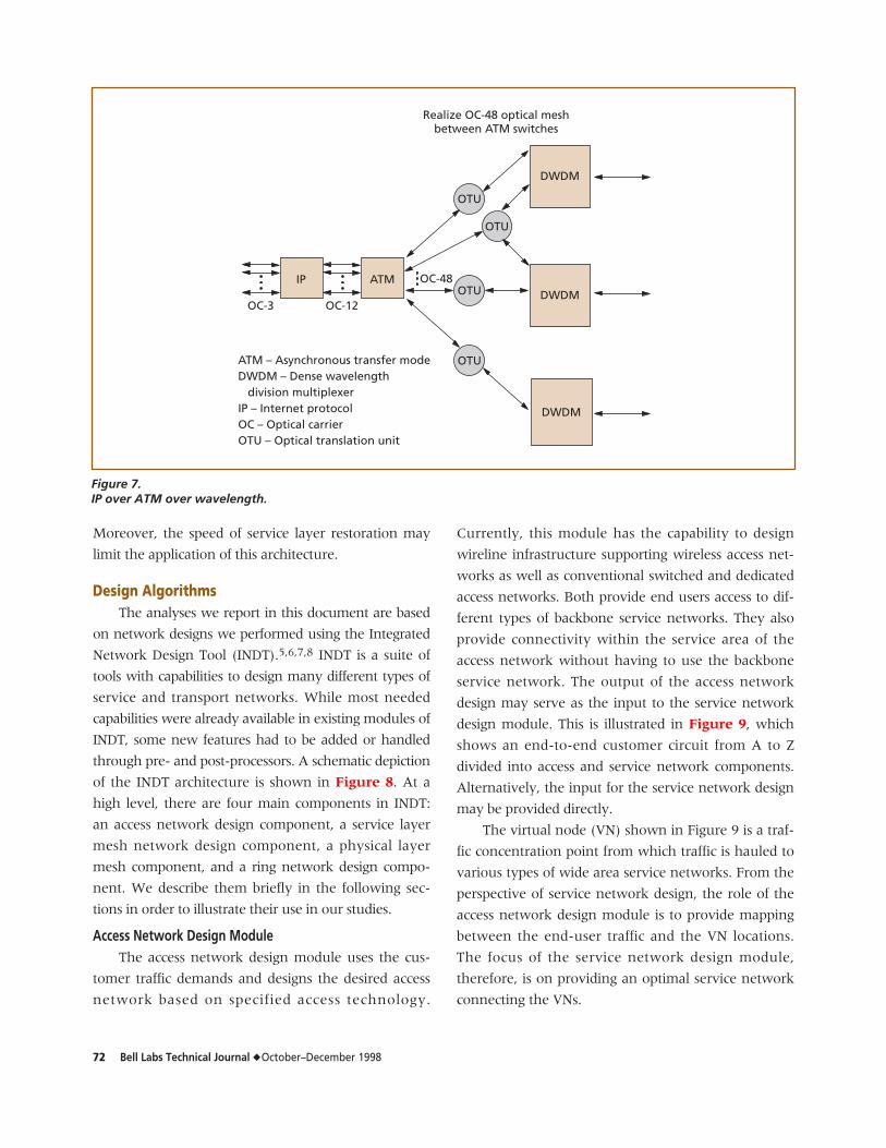
routing is at the service layer. Figures 6 and 7 depict
the nodal views of networks carrying IP over wave-
length and IP over ATM over wavelength with service
layer restoration. The advantage of this architecture
over architecture 2 is the elimination of a layer of
equipment and, possibly, the realization of efficiency
from service layer restoration. On the other hand,
inefficiencies are introduced from the lack of a multi-
plexing layer between the service and optical layers.
HS
DWDM – Dense wavelength division multiplexerHS – High speedIP – Internet protocolLS – Low speedOC – Optical carrierOTU – Optical translation unitSTS – Synchronous transfer signalUXC – Ultra-cross connect (SONET multiplexer and optical cross connect)
IP LS
UXC
OTU
DWDM
DWDM
OC-192
Realize OC-192mesh
OC-3 OC-48
STS-48
DWDM
OTU
OTU
OTU
Figure 4.IP over optical mesh transport.
Bell Labs Technical Journal ◆ October–December 1998 71
ATM – Asynchronous transfer modeDWDM – Dense wavelength division multiplexerHS – High speedIP – Internet protocolLS – Low speedOC – Optical carrierOTU – Optical translation unitSTS – Synchronous transfer signalUXC – Ultra-cross connect (SONET multiplexer and optical cross connect)
IP
OC-3 OC-48
ATM
OC-12
HSLS
UXC
OTU
DWDM
DWDM
OC-192
Realize OC-192mesh
STS-48
DWDM
OTU
OTU
OTU
Figure 5.IP over ATM over optical mesh transport.
DWDM – Dense wavelength division multiplexerIP – Internet protocolOC – Optical carrierOTU – Optical translation unit
IP
OC-3
OTU
DWDM
DWDM
OC-48
Realize OC-48 optical meshbetween IP routers
DWDM
OTU
OTU
OTU
Figure 6.IP over wavelength (optical channel).
72 Bell Labs Technical Journal ◆ October–December 1998
Moreover, the speed of service layer restoration may
limit the application of this architecture.
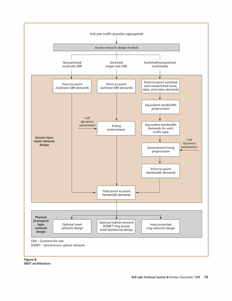
Design AlgorithmsThe analyses we report in this document are based
on network designs we performed using the Integrated
Network Design Tool (INDT).5,6,7,8 INDT is a suite of
tools with capabilities to design many different types of
service and transport networks. While most needed
capabilities were already available in existing modules of
INDT, some new features had to be added or handled
through pre- and post-processors. A schematic depiction
of the INDT architecture is shown in Figure 8. At a
high level, there are four main components in INDT:
an access network design component, a service layer
mesh network design component, a physical layer
mesh component, and a ring network design compo-
nent. We describe them briefly in the following sec-
tions in order to illustrate their use in our studies.
Access Network Design ModuleThe access network design module uses the cus-
tomer traffic demands and designs the desired access
network based on specified access technology.
Currently, this module has the capability to design
wireline infrastructure supporting wireless access net-
works as well as conventional switched and dedicated
access networks. Both provide end users access to dif-
ferent types of backbone service networks. They also
provide connectivity within the service area of the
access network without having to use the backbone
service network. The output of the access network
design may serve as the input to the service network
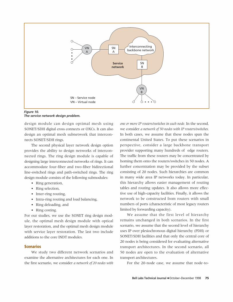
design module. This is illustrated in Figure 9, which
shows an end-to-end customer circuit from A to Z
divided into access and service network components.
Alternatively, the input for the service network design
may be provided directly.
The virtual node (VN) shown in Figure 9 is a traf-
fic concentration point from which traffic is hauled to
various types of wide area service networks. From the
perspective of service network design, the role of the
access network design module is to provide mapping
between the end-user traffic and the VN locations.
The focus of the service network design module,
therefore, is on providing an optimal service network
connecting the VNs.
ATM – Asynchronous transfer modeDWDM – Dense wavelength division multiplexerIP – Internet protocolOC – Optical carrierOTU – Optical translation unit
ATM
OC-12
OTU
DWDM
DWDM
OC-48
Realize OC-48 optical meshbetween ATM switches
DWDM
OTU
OTU
OTU
IP
OC-3
Figure 7.IP over ATM over wavelength.
Bell Labs Technical Journal ◆ October–December 1998 73
End-user traffic (possibly aggregated)
Access network design module
Nonswitchedmultirate CBR
Switchedsingle-rate CBR
Switched/nonswitchedmultimedia
Point-to-pointmultirate CBR demands
Point-to-pointswitched CBR demands
Point-to-point switchedand nonswitched voice,
data, and video demands
Equivalent bandwidthpreprocessor
Equivalent bandwidthdemands for each
traffic type
Generalized Erlangpreprocessor
Point-to-pointbandwidth demands
Erlangpreprocessor
Calldynamics
parameters
Calldynamics
parameters
Total point-to-pointbandwidth demands
Optimal hybrid network(SONET ring access/
mesh backbone) design
Service layermesh network
design
Physical(transport)
layernetworkdesign
Optimal meshnetwork design
Interconnectedring network design
CBR – Constant bit rateSONET – Synchronous optical network
Figure 8.INDT architecture.
74 Bell Labs Technical Journal ◆ October–December 1998
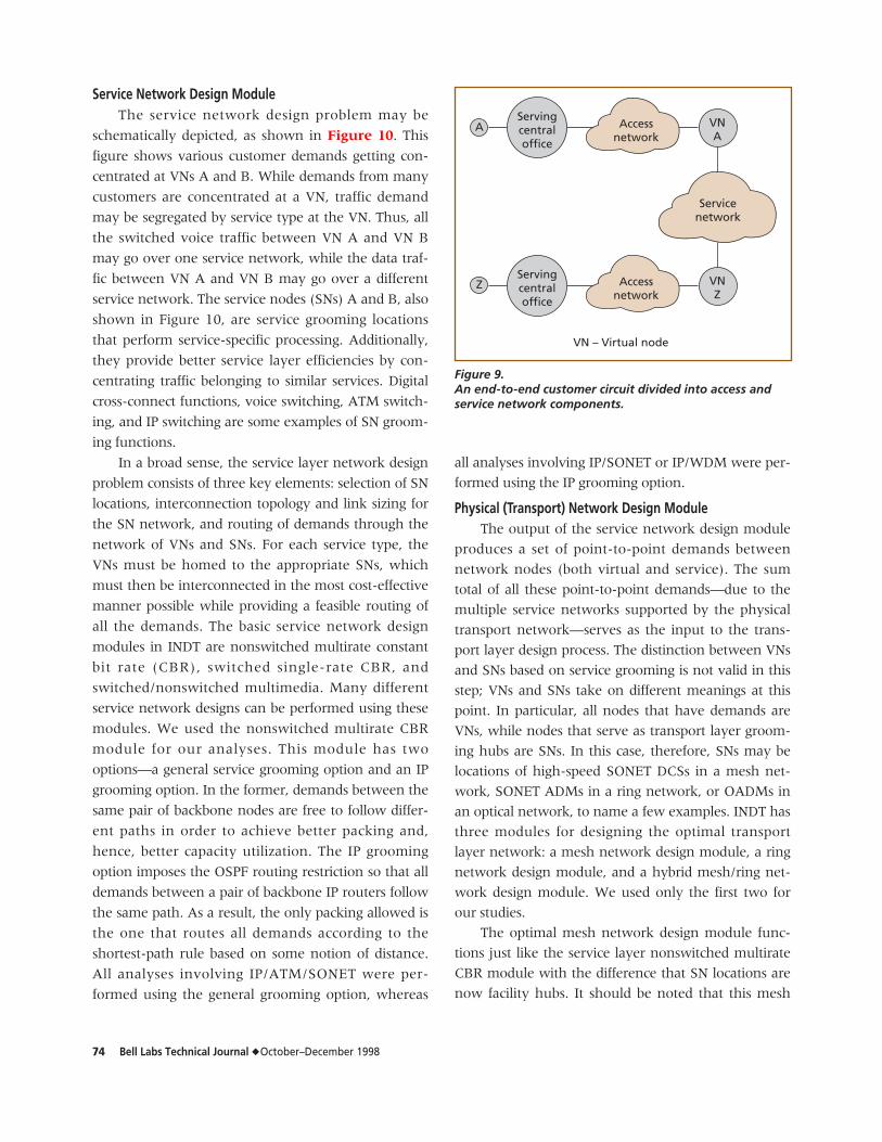
Service Network Design ModuleThe service network design problem may be
schematically depicted, as shown in Figure 10. This
figure shows various customer demands getting con-
centrated at VNs A and B. While demands from many
customers are concentrated at a VN, traffic demand
may be segregated by service type at the VN. Thus, all
the switched voice traffic between VN A and VN B
may go over one service network, while the data traf-
fic between VN A and VN B may go over a different
service network. The service nodes (SNs) A and B, also
shown in Figure 10, are service grooming locations
that perform service-specific processing. Additionally,
they provide better service layer efficiencies by con-
centrating traffic belonging to similar services. Digital
cross-connect functions, voice switching, ATM switch-
ing, and IP switching are some examples of SN groom-
ing functions.
In a broad sense, the service layer network design
problem consists of three key elements: selection of SN
locations, interconnection topology and link sizing for
the SN network, and routing of demands through the
network of VNs and SNs. For each service type, the
VNs must be homed to the appropriate SNs, which
must then be interconnected in the most cost-effective
manner possible while providing a feasible routing of
all the demands. The basic service network design
modules in INDT are nonswitched multirate constant
bit rate (CBR), switched single-rate CBR, and
switched/nonswitched multimedia. Many different
service network designs can be performed using these
modules. We used the nonswitched multirate CBR
module for our analyses. This module has two
options—a general service grooming option and an IP
grooming option. In the former, demands between the
same pair of backbone nodes are free to follow differ-
ent paths in order to achieve better packing and,
hence, better capacity utilization. The IP grooming
option imposes the OSPF routing restriction so that all
demands between a pair of backbone IP routers follow
the same path. As a result, the only packing allowed is
the one that routes all demands according to the
shortest-path rule based on some notion of distance.
All analyses involving IP/ATM/SONET were per-
formed using the general grooming option, whereas
all analyses involving IP/SONET or IP/WDM were per-
formed using the IP grooming option.
Physical (Transport) Network Design ModuleThe output of the service network design module
produces a set of point-to-point demands between
network nodes (both virtual and service). The sum
total of all these point-to-point demands—due to the
multiple service networks supported by the physical
transport network—serves as the input to the trans-
port layer design process. The distinction between VNs
and SNs based on service grooming is not valid in this
step; VNs and SNs take on different meanings at this
point. In particular, all nodes that have demands are
VNs, while nodes that serve as transport layer groom-
ing hubs are SNs. In this case, therefore, SNs may be
locations of high-speed SONET DCSs in a mesh net-
work, SONET ADMs in a ring network, or OADMs in
an optical network, to name a few examples. INDT has
three modules for designing the optimal transport
layer network: a mesh network design module, a ring
network design module, and a hybrid mesh/ring net-
work design module. We used only the first two for
our studies.
The optimal mesh network design module func-
tions just like the service layer nonswitched multirate
CBR module with the difference that SN locations are
now facility hubs. It should be noted that this mesh
Servicenetwork
VNA
VNZ
Accessnetwork
AServingcentraloffice
Accessnetwork
Servingcentraloffice
VN – Virtual node
Z
Figure 9.An end-to-end customer circuit divided into access andservice network components.
Bell Labs Technical Journal ◆ October–December 1998 75
design module can design optimal mesh using
SONET/SDH digital cross connects or OXCs. It can also
design an optimal mesh subnetwork that intercon-
nects SONET/SDH rings.
The second physical layer network design option
provides the ability to design networks of intercon-
nected rings. The ring design module is capable of
designing large interconnected networks of rings. It can
accommodate four-fiber and two-fiber bidirectional
line-switched rings and path-switched rings. The ring
design module consists of the following submodules:
• Ring generation,
• Ring selection,
• Inter-ring routing,
• Intra-ring routing and load balancing,
• Ring deloading, and
• Ring costing.
For our studies, we use the SONET ring design mod-
ule, the optimal mesh design module with optical
layer restoration, and the optimal mesh design module
with service layer restoration. The last two include
additions to the core INDT modules.
ScenariosWe study two different network scenarios and
examine the alternative architectures for each one. In
the first scenario, we consider a network of 20 nodes with
one or more IP routers/switches in each node. In the second,
we consider a network of 50 nodes with IP routers/switches.
In both cases, we assume that these nodes span the
continental United States. To put these scenarios in
perspective, consider a large backbone transport
provider supporting many hundreds of edge routers.
The traffic from these routers may be concentrated by
homing them onto the routers/switches in 50 nodes. A
further concentration may be provided by the subset
consisting of 20 nodes. Such hierarchies are common
in many wide area IP networks today. In particular,
this hierarchy allows easier management of routing
tables and routing updates. It also allows more effec-
tive use of high-capacity facilities. Finally, it allows the
network to be constructed from routers with small
numbers of ports (characteristic of most legacy routers
limited by forwarding capacity).
We assume that the first level of hierarchy
remains unchanged in both scenarios. In the first
scenario, we assume that the second level of hierarchy
uses IP over plesiochronous digital hierarchy (PDH) or
SONET/SDH facilities and that only the central core of
20 nodes is being considered for evaluating alternative
transport architectures. In the second scenario, all
50 nodes are open to the evaluation of alternative
transport architectures.
For the 20-node case, we assume that node-to-
Interconnectingbackbone network
VNA
SNA
SNB
VNB
Servicenetwork
SN – Service nodeVN – Virtual node
Figure 10.The service network design problem.
76 Bell Labs Technical Journal ◆ October–December 1998
node demands are specified in multiples of OC-3 and
that high-speed interfaces to the IP and ATM switches
are OC-12 or OC-48. Starting with a demand matrix,
we scale the demands to reflect various growth scenar-
ios. As noted earlier, IP traffic follows the OSPF rout-
ing restriction in the absence of an ATM layer; the
ATM layer allows more flexible routing and facility
packing. We consider two types of IP routers/switches:
legacy routers that are limited by the forwarding
capacity (assumed to be 75% of the aggregate link
capacities) and IP switches with wire-speed input pro-
cessing that are, therefore, limited by the aggregate
link capacities. The former will be indicated as for-
warding capacity limited (FC). For each of the six
scenarios—(IP-FC, OC-12); (IP, OC-12); (IP-FC, OC-48);
(IP, OC-48); (IP over ATM, OC-12); and (IP over ATM,
OC-48)—we consider all three physical transport
options. For the second scenario, the demand matrices
are in terms of DS3. The interface speeds investigated
for IP and ATM switches are OC-3, OC-12, and OC-48.
Once again, we consider different core transport archi-
tectures for IP with or without ATM.
We use existing INDT modules, several experi-
mental modules, and many pre-/post-processors to
generate optimal designs and their characteristics—for
example, the numbers of IP ports, ATM ports, OC-12
miles, OC-48 miles, BWM ports, OXC ports, fiber
miles, wavelengths used per fiber, optical amplifiers,
and regenerators. For a subset of combinations, we use
representative equipment prices to compare alterna-
tives from an equipment cost perspective. While
equipment costs are relatively easy to compare among
architectures, fiber cost is not as easy to assign.
Equipment costs in conjunction with usage statistics
on facilities allow comparisons of different transport
architectures under different embedded bases of opti-
cal fiber.
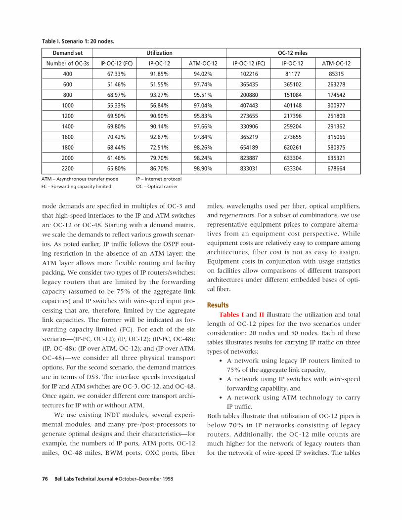
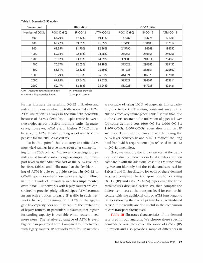
ResultsTables I and II illustrate the utilization and total
length of OC-12 pipes for the two scenarios under
consideration: 20 nodes and 50 nodes. Each of these
tables illustrates results for carrying IP traffic on three
types of networks:
• A network using legacy IP routers limited to
75% of the aggregate link capacity,
• A network using IP switches with wire-speed
forwarding capability, and
• A network using ATM technology to carry
IP traffic.
Both tables illustrate that utilization of OC-12 pipes is
below 70% in IP networks consisting of legacy
routers. Additionally, the OC-12 mile counts are
much higher for the network of legacy routers than
for the network of wire-speed IP switches. The tables
Demand set Utilization OC-12 miles
Number of OC-3s IP-OC-12 (FC) IP-OC-12 ATM-OC-12 IP-OC-12 (FC) IP-OC-12 ATM-OC-12
400 67.33% 91.85% 94.02% 102216 81177 85315
600 51.46% 51.55% 97.74% 365435 365102 263278
800 68.97% 93.27% 95.51% 200880 151084 174542
1000 55.33% 56.84% 97.04% 407443 401148 300977
1200 69.50% 90.90% 95.83% 273655 217396 251809
1400 69.80% 90.14% 97.66% 330906 259204 291362
1600 70.42% 92.67% 97.84% 365219 273655 315066
1800 68.44% 72.51% 98.26% 654189 620261 580375
2000 61.46% 79.70% 98.24% 823887 633304 635321
2200 65.80% 86.70% 98.90% 833031 633304 678664
Table I. Scenario 1: 20 nodes.
ATM – Asynchronous transfer mode
FC – Forwarding capacity limited
IP – Internet protocol
OC – Optical carrier
Bell Labs Technical Journal ◆ October–December 1998 77
further illustrate the resulting OC-12 utilization and
miles for the case in which IP traffic is carried as ATM.
ATM utilization is always in the ninetieth percentile
because of ATM’s flexibility to split traffic between
two nodes across possible multiple paths. In many
cases, however, ATM yields higher OC-12 miles
because, in ATM, flexible routing is not able to com-
pensate for the 20% ATM cell tax.
To be the optimal choice to carry IP traffic, ATM
must yield savings in pipe miles even after compensat-
ing for the 20% cell tax. Moreover, the savings in pipe
miles must translate into enough savings at the trans-
port level so that additional cost at the ATM level can
be offset. Tables I and II illustrate that the flexible rout-
ing of ATM is able to provide savings in OC-12 or
OC-48 pipe miles when these pipes are lightly utilized
in the network of IP routers/switches implemented
over SONET. IP networks with legacy routers are con-
strained to provide lightly utilized pipes; ATM becomes
an attractive option to carry IP traffic in such net-
works. In fact, our assumption of 75% of the aggre-
gate link capacity does not fully capture the limitations
of legacy routers. In particular, it assumes that higher
forwarding capacity is available when routers need
more ports. The relative advantage of ATM is even
higher than presented here. Compared to IP networks
with legacy routers, IP networks with fast IP switches
are capable of using 100% of aggregate link capacity
but, due to the OSPF routing constraint, may not be
able to effectively utilize pipes. Table I shows that, due
to the OSPF constraint, the utilization of pipes is lower
for some demand sets (600 OC-3s; 1,000 OC-3s;
1,800 OC-3s; 2,000 OC-3s) even after using fast IP
switches. These are the cases in which having the
ATM layer between IP and SONET reduces the long
haul bandwidth requirements (as reflected in OC-12
or OC-48 pipe miles).
Next, we quantify the impact on cost at the trans-
port level due to differences in OC-12 miles and then
compare it with the additional cost of ATM functional-
ity. We consider only 3 of the 10 demand sets used for
Tables I and II. Specifically, for each of these demand
sets, we compute the transport cost for carrying
OC-12 (IP) and OC-12 (ATM) pipes over the three
architectures discussed earlier. We then compare the
difference in cost at the transport level for each archi-
tecture with the additional cost of ATM functionality.
Besides showing the overall picture for a facility-based
carrier, these results are also useful in the comparison
of core transport alternatives.
Table III illustrates characteristics of the demand
sets used in our analysis. We choose these specific
demands because they cover the range of OC-12 (IP)
utilization and also provide a range of differences in
ATM – Asynchronous transfer mode
FC – Forwarding capacity limited
IP – Internet protocol
OC – Optical carrier
Demand set Utilization OC-12 miles
Number of OC-3s IP-OC-12 (FC) IP-OC-12 ATM-OC-12 IP-OC-12 (FC) IP-OC-12 ATM-OC-12
400 67.70% 87.32% 89.11% 147287 113775 101003
600 69.27% 89.61% 91.65% 185195 158188 137817
800 69.65% 91.70% 92.96% 245190 186568 194750
1000 69.04% 92.33% 94.48% 285551 230353 249266
1200 70.87% 93.73% 94.59% 309885 240914 284068
1400 70.27% 92.05% 94.18% 373022 290386 339430
1600 66.31% 92.62% 95.39% 431738 332651 375502
1800 70.29% 91.53% 96.53% 444024 346670 397601
2000 67.99% 93.64% 95.57% 523527 394861 453714
2200 69.17% 88.86% 95.94% 553023 447733 478481
Table II. Scenario 2: 50 nodes.
78 Bell Labs Technical Journal ◆ October–December 1998
OC-12 (ATM) miles. Note that for this analysis, we use
only IP networks with wire-speed IP switches because
they represent the emerging technology and because
they represent the lower bounds on savings possible
with the intervening ATM layer. The demands are
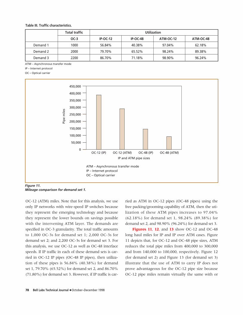
specified in OC-3 granularity. The total traffic amounts
to 1,000 OC-3s for demand set 1; 2,000 OC-3s for
demand set 2; and 2,200 OC-3s for demand set 3. For
this analysis, we use OC-12 as well as OC-48 interface
speeds. If IP traffic in each of these demand sets is car-
ried in OC-12 IP pipes (OC-48 IP pipes), then utiliza-
tion of these pipes is 56.84% (40.38%) for demand
set 1, 79.70% (65.52%) for demand set 2, and 86.70%
(71.80%) for demand set 3. However, if IP traffic is car-
ried as ATM in OC-12 pipes (OC-48 pipes) using the
free packing/grooming capability of ATM, then the uti-
lization of these ATM pipes increases to 97.04%
(62.18%) for demand set 1, 98.24% (89.38%) for
demand set 2, and 98.90% (96.24%) for demand set 3.
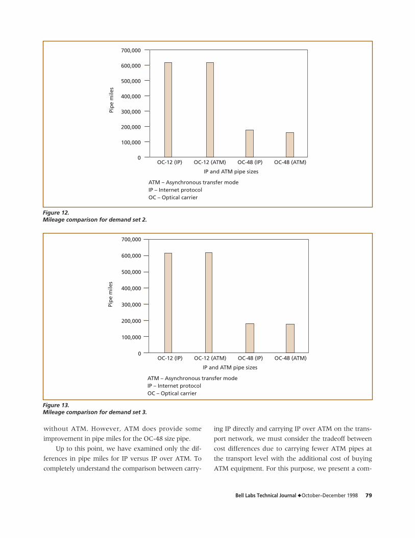
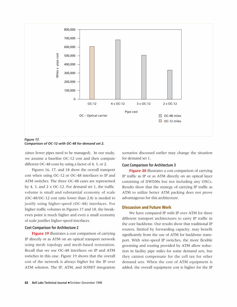
Figures 11, 12, and 13 show OC-12 and OC-48
long haul miles for IP and IP over ATM cases. Figure
11 depicts that, for OC-12 and OC-48 pipe sizes, ATM
reduces the total pipe miles from 400,000 to 300,000
and from 140,000 to 100,000, respectively. Figure 12
(for demand set 2) and Figure 13 (for demand set 3)
illustrate that the use of ATM to carry IP does not
prove advantageous for the OC-12 pipe size because
OC-12 pipe miles remain virtually the same with or
Total traffic Utilization
OC-3 IP-OC-12 IP-OC-48 ATM-OC-12 ATM-OC-48
Demand 1 1000 56.84% 40.38% 97.04% 62.18%
Demand 2 2000 79.70% 65.52% 98.24% 89.38%
Demand 3 2200 86.70% 71.18% 98.90% 96.24%
Table III. Traffic characteristics.
ATM – Asynchronous transfer mode
IP – Internet protocol
OC – Optical carrier
OC-12 (IP) OC-12 (ATM) OC-48 (IP) OC-48 (ATM)
450,000
400,000
350,000
300,000
250,000
200,000
150,000
100,000
50,000
0
IP and ATM pipe sizes
Pip
e m
iles
ATM – Asynchronous transfer modeIP – Internet protocolOC – Optical carrier
Figure 11.Mileage comparison for demand set 1.
Bell Labs Technical Journal ◆ October–December 1998 79
without ATM. However, ATM does provide some
improvement in pipe miles for the OC-48 size pipe.
Up to this point, we have examined only the dif-
ferences in pipe miles for IP versus IP over ATM. To
completely understand the comparison between carry-
ing IP directly and carrying IP over ATM on the trans-
port network, we must consider the tradeoff between
cost differences due to carrying fewer ATM pipes at
the transport level with the additional cost of buying
ATM equipment. For this purpose, we present a com-
OC-12 (IP) OC-12 (ATM) OC-48 (IP) OC-48 (ATM)
700,000
600,000
500,000
400,000
300,000
200,000
100,000
0
IP and ATM pipe sizes
Pip
e m
iles
ATM – Asynchronous transfer modeIP – Internet protocolOC – Optical carrier
Figure 12.Mileage comparison for demand set 2.
OC-12 (IP) OC-12 (ATM) OC-48 (IP) OC-48 (ATM)
700,000
600,000
500,000
400,000
300,000
200,000
100,000
0
IP and ATM pipe sizes
Pip
e m
iles
ATM – Asynchronous transfer modeIP – Internet protocolOC – Optical carrier
Figure 13.Mileage comparison for demand set 3.
80 Bell Labs Technical Journal ◆ October–December 1998
parison of cost savings at the transport level for three
transport architectures (described earlier) with the
additional ATM equipment cost. Note that in our cost
comparison, we use normalized cost numbers instead
of absolute cost numbers. Note also that there is no cost
associated with the optical fiber itself. Only equipment
costs—for example, BWM, DWDM, optical amplifier,
and regenerator costs—are included in this analysis.
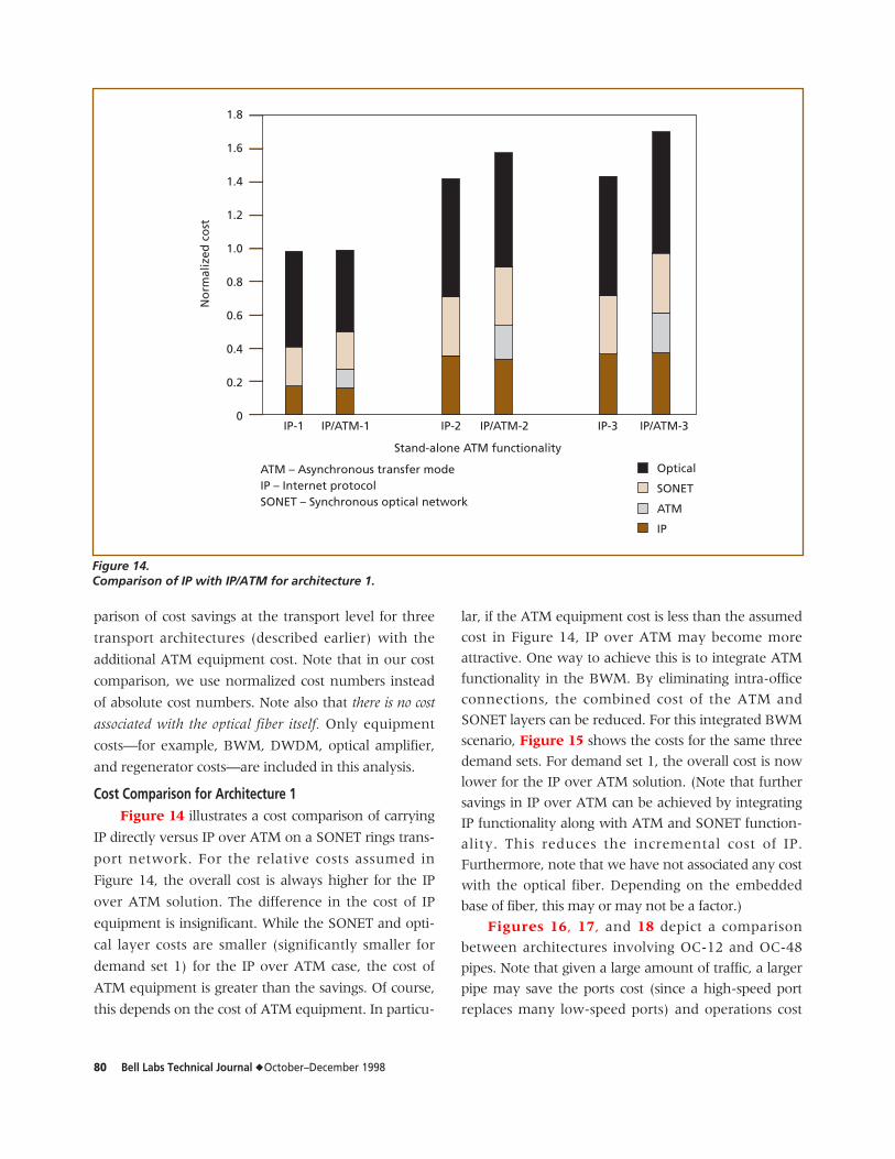
Cost Comparison for Architecture 1Figure 14 illustrates a cost comparison of carrying
IP directly versus IP over ATM on a SONET rings trans-
port network. For the relative costs assumed in
Figure 14, the overall cost is always higher for the IP
over ATM solution. The difference in the cost of IP
equipment is insignificant. While the SONET and opti-
cal layer costs are smaller (significantly smaller for
demand set 1) for the IP over ATM case, the cost of
ATM equipment is greater than the savings. Of course,
this depends on the cost of ATM equipment. In particu-
lar, if the ATM equipment cost is less than the assumed
cost in Figure 14, IP over ATM may become more
attractive. One way to achieve this is to integrate ATM
functionality in the BWM. By eliminating intra-office
connections, the combined cost of the ATM and
SONET layers can be reduced. For this integrated BWM
scenario, Figure 15 shows the costs for the same three
demand sets. For demand set 1, the overall cost is now
lower for the IP over ATM solution. (Note that further
savings in IP over ATM can be achieved by integrating
IP functionality along with ATM and SONET function-
ality. This reduces the incremental cost of IP.
Furthermore, note that we have not associated any cost
with the optical fiber. Depending on the embedded
base of fiber, this may or may not be a factor.)
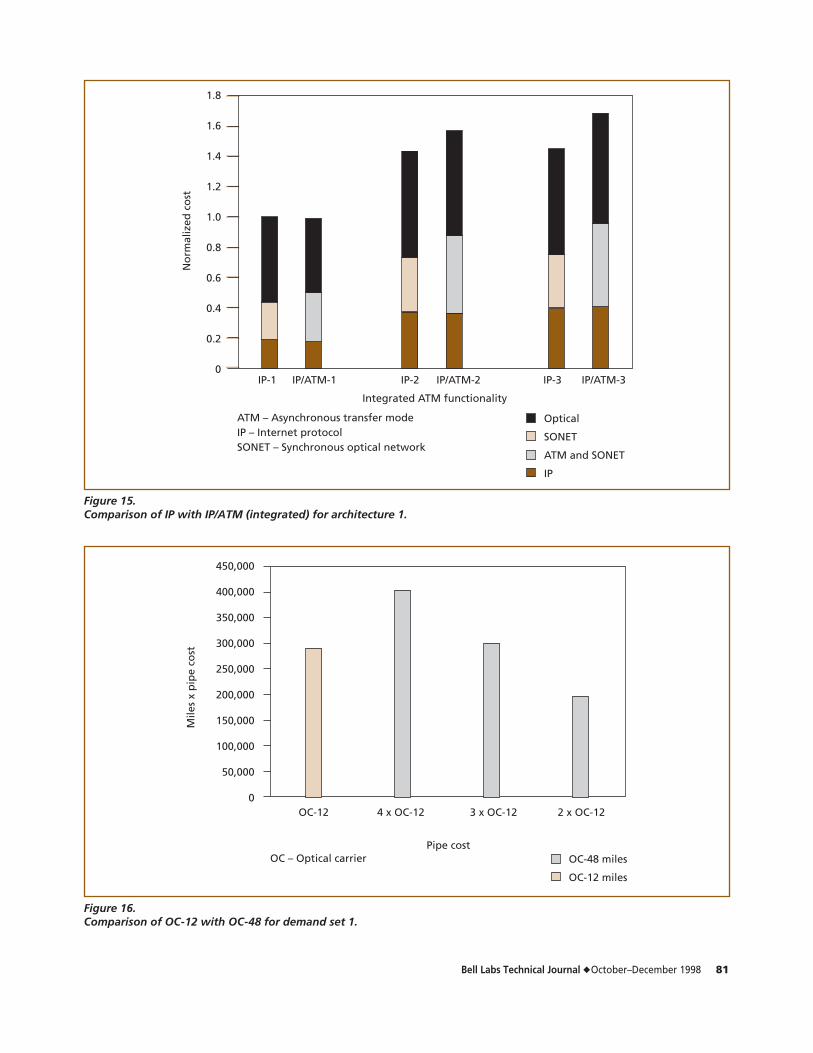
Figures 16, 17, and 18 depict a comparison
between architectures involving OC-12 and OC-48
pipes. Note that given a large amount of traffic, a larger
pipe may save the ports cost (since a high-speed port
replaces many low-speed ports) and operations cost
1.8
1.6
1.4
1.2
1.0
0.8
0.6
0.4
0.2
0
No
rmal
ized
co
st
Stand-alone ATM functionality
IP-1 IP/ATM-1 IP-2 IP/ATM-2 IP-3 IP/ATM-3
Optical
SONET
ATM
IP
ATM – Asynchronous transfer modeIP – Internet protocolSONET – Synchronous optical network
Figure 14.Comparison of IP with IP/ATM for architecture 1.
Bell Labs Technical Journal ◆ October–December 1998 81
1.8
1.6
1.4
1.2
1.0
0.8
0.6
0.4
0.2
0
No
rmal
ized
co
st
Integrated ATM functionality
ATM – Asynchronous transfer modeIP – Internet protocolSONET – Synchronous optical network
IP-1 IP/ATM-1 IP-2 IP/ATM-2 IP-3 IP/ATM-3
Optical
SONET
ATM and SONET
IP
Figure 15.Comparison of IP with IP/ATM (integrated) for architecture 1.
OC – Optical carrier OC-48 miles
OC-12 miles
450,000
400,000
350,000
300,000
250,000
200,000
150,000
100,000
50,000
0
Mile
s x
pip
e co
st
Pipe cost
OC-12 4 x OC-12 3 x OC-12 2 x OC-12
Figure 16.Comparison of OC-12 with OC-48 for demand set 1.
82 Bell Labs Technical Journal ◆ October–December 1998
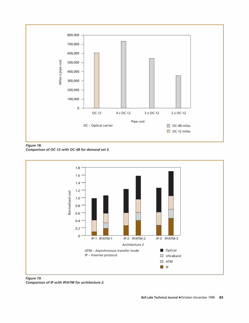
(since fewer pipes need to be managed). In our study,
we assume a baseline OC-12 cost and then compute
different OC-48 costs by using a factor of 4, 3, or 2.
Figures 16, 17, and 18 show the overall transport
cost when using OC-12 or OC-48 interfaces to IP and
ATM switches. The three OC-48 cases are represented
by 4, 3, and 2 x OC-12. For demand set 1, the traffic
volume is small and substantial economy of scale
(OC-48/OC-12 cost ratio lower than 2.8) is needed to
justify using higher-speed (OC-48) interfaces. For
higher traffic volumes in Figures 17 and 18, the break-
even point is much higher and even a small economy
of scale justifies higher-speed interfaces.
Cost Comparison for Architecture 2Figure 19 illustrates a cost comparison of carrying
IP directly or as ATM on an optical transport network
using mesh topology and mesh-based restoration.
Recall that we use OC-48 interfaces on IP and ATM
switches in this case. Figure 19 shows that the overall
cost of the network is always higher for the IP over
ATM solution. The IP, ATM, and SONET integration
scenarios discussed earlier may change the situation
for demand set 1.
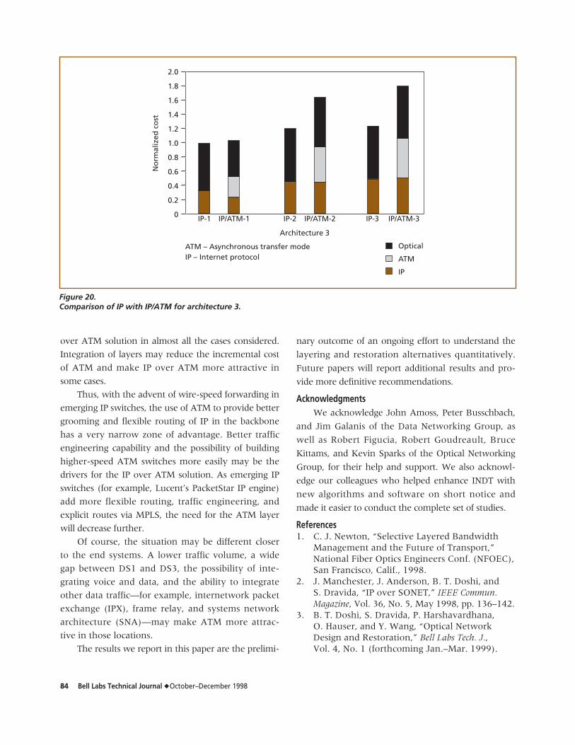
Cost Comparison for Architecture 3Figure 20 illustrates a cost comparison of carrying
IP traffic as IP or as ATM directly on an optical layer
consisting of DWDMs but not including any OXCs.
Results show that the strategy of carrying IP traffic as
ATM to utilize better ATM packing does not prove
advantageous for this architecture.
Discussion and Future WorkWe have compared IP with IP over ATM for three
different transport architectures to carry IP traffic in
the core backbone. Our results show that traditional IP
routers, limited by forwarding capacity, may benefit
significantly from the use of ATM for backbone trans-
port. With wire-speed IP switches, the more flexible
grooming and routing provided by ATM allow reduc-
tion in facility pipe miles for some demand sets, but
they cannot compensate for the cell tax for other
demand sets. When the cost of ATM equipment is
added, the overall equipment cost is higher for the IP
OC – Optical carrier OC-48 miles
OC-12 miles
800,000
700,000
600,000
500,000
400,000
300,000
200,000
100,000
0
Mile
s x
pip
e co
st
Pipe cost
OC-12 4 x OC-12 3 x OC-12 2 x OC-12
Figure 17.Comparison of OC-12 with OC-48 for demand set 2.
Bell Labs Technical Journal ◆ October–December 1998 83
OC – Optical carrier OC-48 miles
OC-12 miles
800,000
700,000
600,000
500,000
400,000
300,000
200,000
100,000
0
Mile
s x
pip
e co
st
Pipe cost
OC-12 4 x OC-12 3 x OC-12 2 x OC-12
Figure 18.Comparison of OC-12 with OC-48 for demand set 3.
1.8
1.6
1.4
1.2
1.0
0.8
0.6
0.4
0.2
0
No
rmal
ized
co
st
Architecture 2
IP-1 IP/ATM-1 IP-2 IP/ATM-2 IP-3 IP/ATM-3
Optical
UltraBand
ATM
IP
ATM – Asynchronous transfer modeIP – Internet protocol
Figure 19.Comparison of IP with IP/ATM for architecture 2.
84 Bell Labs Technical Journal ◆ October–December 1998
over ATM solution in almost all the cases considered.
Integration of layers may reduce the incremental cost
of ATM and make IP over ATM more attractive in
some cases.
Thus, with the advent of wire-speed forwarding in
emerging IP switches, the use of ATM to provide better
grooming and flexible routing of IP in the backbone
has a very narrow zone of advantage. Better traffic
engineering capability and the possibility of building
higher-speed ATM switches more easily may be the
drivers for the IP over ATM solution. As emerging IP
switches (for example, Lucent’s PacketStar IP engine)
add more flexible routing, traffic engineering, and
explicit routes via MPLS, the need for the ATM layer
will decrease further.
Of course, the situation may be different closer
to the end systems. A lower traffic volume, a wide
gap between DS1 and DS3, the possibility of inte-
grating voice and data, and the ability to integrate
other data traffic—for example, internetwork packet
exchange (IPX), frame relay, and systems network
architecture (SNA)—may make ATM more attrac-
tive in those locations.
The results we report in this paper are the prelimi-
nary outcome of an ongoing effort to understand the
layering and restoration alternatives quantitatively.
Future papers will report additional results and pro-
vide more definitive recommendations.
AcknowledgmentsWe acknowledge John Amoss, Peter Busschbach,
and Jim Galanis of the Data Networking Group, as
well as Robert Figucia, Robert Goudreault, Bruce
Kittams, and Kevin Sparks of the Optical Networking
Group, for their help and support. We also acknowl-
edge our colleagues who helped enhance INDT with
new algorithms and software on short notice and
made it easier to conduct the complete set of studies.
References1. C. J. Newton, “Selective Layered Bandwidth
Management and the Future of Transport,”National Fiber Optics Engineers Conf. (NFOEC),San Francisco, Calif., 1998.
2. J. Manchester, J. Anderson, B. T. Doshi, andS. Dravida, “IP over SONET,” IEEE Commun.Magazine, Vol. 36, No. 5, May 1998, pp. 136–142.
3. B. T. Doshi, S. Dravida, P. Harshavardhana,O. Hauser, and Y. Wang, “Optical NetworkDesign and Restoration,” Bell Labs Tech. J., Vol. 4, No. 1 (forthcoming Jan.–Mar. 1999).
2.0
1.8
1.6
1.4
1.2
1.0
0.8
0.6
0.4
0.2
0
No
rmal
ized
co
st
Architecture 3
IP-1 IP/ATM-1 IP-2 IP/ATM-2 IP-3 IP/ATM-3
Optical
ATM
IP
ATM – Asynchronous transfer modeIP – Internet protocol
Figure 20.Comparison of IP with IP/ATM for architecture 3.
Bell Labs Technical Journal ◆ October–December 1998 85
4. V. P. Kumar, T. V. Lakshman, and D. Stiliadis,“Beyond Best Effort: Router Architectures forthe Differentiated Services of Tomorrow’sInternet,” IEEE Commun. Magazine, Vol. 36, No. 5, May 1998, pp. 152–164.
5. B. T. Doshi, S. Dravida, and P. Harshavardhana,“Overview of INDT—A New Tool for Next-Generation Network Design,” Proc. IEEEGLOBECOM, 1995, pp. 1942–1946.
6. S. Dravida, Hong Jiang, M. Kodialam, B. Samadi,and Yufei Wang, “Narrowband and BroadbandInfrastructure Design for Wireless Networks,”IEEE Commun. Magazine, Vol. 36, No. 5, May 1998, pp. 72–78.
7. D. S. Johnson, C. R. Aragon, L. A. McGeoch,and C. Schevon, “Optimization by SimulatedAnnealing: an Experimental Evaluation. Part I.Graph Partitioning,” Operations Research, Vol. 37,No. 6, Nov.–Dec. 1989, pp. 865–892.
8. B. T. Doshi and P. Harshavardhana, “BroadbandNetwork Infrastructure of the Future: Roles ofNetwork Design Tools in Technology Deploy-ment Strategies,” IEEE Commun. Magazine, Vol. 36, No. 5, May 1998, pp. 60–71.
(Manuscript approved December 1998)
BHARAT T. DOSHI, who holds a Ph.D. in operationsresearch from Cornell University in Ithaca,New York, is head of the PerformanceAnalysis Department at Bell Labs in Holmdel,New Jersey. Dr. Doshi is responsible for pro-tocol designs, performance analysis, traffic
management, routing and restoration algorithms, andarchitecture of next-generation converged networks.Recent work has focused on wireless, HFC, Internet,SONET, WDM, and ATM technologies, as well as oninterworking among these technologies. Dr. Doshi, whohas authored more than 100 technical papers and sub-mitted 35 patent applications, is both a Bell Labs and anIEEE Fellow.
SUBRAHMANYAM DRAVIDA was a technical managerin the Performance Analysis Department atBell Labs in Holmdel, New Jersey, when thiswork was performed. He holds a B.Tech.degree in electrical engineering from theIndian Institute of Technology in Madras,
as well as M.S.E.E. and Ph.D. degrees in electrical engi-neering from the Rensselaer Polytechnic Institute inTroy, New York. While at Bell Labs, Dr. Dravida workedon protocols and architectures for wireless networks, aswell as protocols for cable networks. His responsibilities
included development of algorithms for the design ofATM, SDH, and wireless networks.
P. HARSHAVARDHANA is a technical manager in thePerformance Analysis Department at BellLabs in Holmdel, New Jersey. He holds aB.Tech. degree in electronics from theIndian Institute of Technology in Madras, aswell as M.S. and Ph.D. degrees in electrical
engineering from the University of Southern Californiain Los Angeles. Dr. Harshavardhana is working on thedesign and analysis of optical, SONET/SDH, and datanetworks. He is responsible for analyzing the networkimpact of product features and alternatives and formodeling the performance of systems and networks.He has authored numerous technical papers and holdsover 20 patents.
M. AKBER QURESHI is a member of technical staff in thePerformance Analysis Department at Bell Labsin Holmdel, New Jersey. He holds a B.E.degree in electrical engineering from N.E.D.University in Karachi, Pakistan, as well asM.S. and Ph.D. degrees in computer engineer-
ing from the University of Arizona at Tucson. He was aVisiting Research Scholar at the University of Illinois Centerof Reliable and High-Performance Computing in Urbana-Champaign. Dr. Qureshi is interested in performance anddependability evaluation, reward model solution, fault-tolerant computing, numerical methods, network design,and modeling and analysis of parallel/distributed com-puter and communication systems. ◆