Embed Size (px)
Citation preview
International Journal of Electrical Engineering and Computing Vol. 4, No. 2 (2020)
71
Original research paper UDC 621.317.72:[621.397.334:681.32
DOI 10.7251/IJEEC2002071M
A Comparison of 5G Channel Coding Techniques LPDC and Polar Codes
Darija Čarapić1 and Mirjana Maksimović2
1 M:tel a.d. Banja Luka, Bosnia and Herzegovina
2 University of East Sarajevo, Faculty of Electrical Engineering, East Sarajevo, Bosnia and Herzegovina
[email protected], [email protected]
Abstract— The rapid, reliable, and secure data transmission in everyday life and numerous applications is one of the crucial demands of
modern society. Mobile wireless communications have advanced significantly in recent decades. From the first (1G) to fifth-generation
(5G) of mobile communications, the realization of fast and secure communication has always been challenging as data transfer happens
in an imperfect channel environment where noise due to amplification, distortion, and other impairments is present. Channel coding is
key to establishing fast communication with low error probability, implying that choosing the proper channel coding scheme is a
challenging and crucial task. Higher flexibility and reliability, and low computational complexity, latency, and costs are desired coding
technique characteristics. This paper focuses on two 5G channel coding techniques, Low-Density Parity-Check (LDPC) and Polar codes.
These codes have been examined in the case of variable message sizes and for a wide range of code rates. In addition, different Polar
decoding algorithms have been investigated. Simulations results have confirmed that there is no single channel coding scheme able to
meet all 5G requirements as well as the superiorities of LDPC codes in case of long messages and Polar codes for short messages. The
ability to support a wide range of code lengths and code rates and excellent Bit Error Rate (BER) performances, justify the utilization of
LDPC and Polar codes in 5G communication systems.
Keywords - 5G, LDPC codes, Polar codes, BER, SNR
I. INTRODUCTION
Mobile communication has undergone dramatic changes
over the past few decades, experiencing five generations of
technological evolution. The first generation of mobile
networks, introduced in the 80s of the last century, was based
on analog transmission. 1G was restricted to voice transmission
only and, for the first time in history, mobile networks were
available to all. At the beginning of the 1990s, the second
generation of the mobile network appeared, introducing for the
first time digital transmission via radio link which improved
both capacity and security. While the most important service
remains voice transmission, the use of digital transmission has
also provided novel services like text messaging, conference
calls, call hold, internal roaming, and more. Initially, there were
several different second-generation technologies, such as the
Global System for Mobile Communication (GSM), which was
developed jointly by several European countries. The third
generation of the mobile network, also called the 3G network,
emerged in the early 2000s. The 3G network enables faster
wireless Internet access and for that time, this was a big step
towards a high-quality mobile broadband network. Improving
data capacity services and data transmission, tasks like
browsing, multimedia content sharing, video downloading,
performing video calls, running video games, and participation
on social media platforms have become possible. All this has
been achieved through the evolution of 3G - HSPA (High-
Speed Packet Access). In 2009, the fourth generation (4G) of
the mobile telecommunications network was launched, along
with LTE technology. LTE technology is based on HSPA,
which offers greater efficiency and improved wireless Internet
access in order to allow higher data rates to the end-user. This
is achieved by a transmission that is based on Orthogonal
Frequency-Division Multiplexing (OFDM), and the main
benefits are to allow wider bandwidths and advanced
technologies that use multiple antennas. 4G has resulted in
higher data rates, higher quality, enhanced security, and
reduced costs. Further development goes beyond
communication services between people and makes possible
human-to-machine and machine-to-machine communication.
This refers to the Internet of Things (IoT). Hence, 5G wireless
networks focus on improving the quality of service (QoS), the
reliability of data transmission, and the security of the systems.
Three key parameters influence the provision of good coverage
with very good performance: the first is a far better data rate;
the second is low latency and a third parameter is a large
number of connections. If all of the above parameters are met,
it results in low energy consumption. In order to achieve greater
Darija Čarapić et al.
72
bandwidths, improved capacity, and energy efficiency, the 5G
relies on spatial multiplexing, massive multi-user multiple-
input-multiple-output (MIMO) techniques utilization with
millimeter-waves (mm-waves) in small cell geometries [1-4].
In order to ensure fast and reliable transmission of data,
channel coding, or forward error control coding (FEC) plays an
important role in the network. Since errors occur during the
transmission of data, due to a number of factors in mobile
communications, such as noise or signal attenuation, their
detection and correction are of immense importance. In
previous generations of mobile networks (3G and 4G), turbo
codes were used because they performed well and were reliable.
In 5G, the 3rd Generation Partnership Project (3GPP) decided
to use Low Density Parity Check (LDPC) codes and a relatively
novel type of channel coding – Polar codes. The reason for this
change in channel coding methodology was a significant coding
delay due to numerous processing iterations required for turbo
codes. They were therefore challenging to use in 5G, where
high speeds and low delays were paramount. Since no type of
code can satisfy all the strict requirements of the 5G, it was
decided to use these two code types. In summary, LDPC and
Polar codes have been chosen due to their excellent Bit Error
Rate (BER) performance and fast encoding and decoding
procedures [5]. Polar codes are a fairly simple method of
encoding and decoding and are able to reach channel capacity.
However, they introduce a little higher latency. LDPC codes, in
addition to lower latency, also use the available bandwidth
better than Polar codes [6].
Having in mind that there is no single channel coding
candidate able to meet all 5G requirements and that not
choosing channel coding technique correctly lead to poor
mobile network performances in terms of coverage, data rates,
capacity, and QoS [7, 8], the research devoted to the selection
and implementation of appropriate channel coding techniques
is crucial. Hence, this paper is organized as follows. A short
overview of 5G is given in Section II. Section III presents 5G
channel coding schemes while simulation results (BER vs
Signal-to-Noise Ratio (SNR) graphs for both, LDPC and Polar
codes, in the function of variable code block lengths and code
rates) are shown in Section IV. In addition, the influence of
different Polar decoding algorithms on BER performance have
been investigated. A summary of the performed research and
directions for future research are provided in the Conclusion.
II. AN OVERVIEW OF 5G
The 5G New Radio (NR) is being developed by the 3GPP
as a new technology for radio access in the fifth generation of
mobile networks. The original time frame for developing the
standard was set in March 2017 at RAN#75. There are two
releases, Release-15 and Release-16, while Release-17 is
expected in 2021. The first set of specifications, Release-15,
was finished in June 2018, while the second release was
completed on July 3rd, 2020, slightly delayed by the pandemic
[9-11]
This network as a base uses the LTE network to offer even
higher throughputs and significantly higher wireless internet
efficiency. Since LTE has served as a foundation for 5G NR,
there are similarities between LTE and 5G NR. New radio
networks are structured so that they are compatible with LTE,
but with the aim of enabling higher spectral efficiency, shorter
response time for the user plane, and greater traffic capacity.
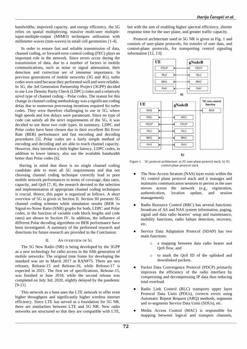
Protocol architecture used in 5G NR is given in Fig. 1 and
consists of user-plane protocols, for transfer of user data, and
control-plane protocols, for transporting control signaling
information [12, 13]:
Figure 1. 5G protocol architecture: a) 5G user-plane protocol stack; b) 5G
control-plane protocol stack
● The Non-Access Stratum (NAS) layer exists within the
5G control plane protocol stack and it manages and
maintains communication sessions to persist as the user
moves across the network (e.g., registration,
authentication, location update, and session
management).
● Radio Resource Control (RRC) has several functions:
broadcast of AS and NAS system information, paging,
signal and data radio bearers’ setup and maintenance,
mobility functions, radio failure detection, recovery,
etc.
● Service Data Adaptation Protocol (SDAP) has two
main functions:
o a mapping between data radio bearer and
QoS flow, and
o to mark the QoS ID of the uplinked and
downlinked packets.
● Packet Data Convergence Protocol (PDCP) primarily
improves the efficiency of the radio interface by
compressing and decompressing IP data thus reducing
total overload.
● Radio Link Control (RLC) transports upper layer
Protocol Data Units (PDUs), corrects errors using
Automatic Repeat Request (ARQ) methods, segments
and re-segments Service Data Units (SDUs), etc.
● Media Access Control (MAC) is responsible for
mapping between logical and transport channels,
International Journal of Electrical Engineering and Computing Vol. 4, No. 2 (2020)
73
scheduling information reporting, correcting errors
using Hybrid Automatic Repeat Request (HARQ),
priority handling of UEs via dynamic scheduling,
multiplexing and demultiplexing of upper layer PDUs,
priority handling between logical channels of one UE
and so on.
● Physical layer transports all information coming from
the MAC layer over the air.
5G network applications can be divided into three
fundamental categories [7, 14, 15]:
● Enhanched mobile broadband (eMBB) - represents a
service improvement initially introduced by 4G LTE
networks that allow higher data rates over a larger area.
Such a network will provide a larger capacity for peak
data rates for bigger crowds and moving users. This
group of applications remains the most important as it
is oriented towards communication between people.
These types of applications are further challenged by
the 5G network. For instance, hot spots require a higher
data rate, a greater number of potential users, and the
need for greater capacity. Furthermore, extensive
coverage is required to allow mobility and a positive
user experience.
● Massive machine-type communications (mMTC) - this
group comprises device-related applications and its
specificity is a large number of interconnected devices
communicating intermittently while exchanging small
amounts of data. High data rates are not necessarily
needed for such applications. However, they should be
able to support asynchronous access (intermittent
network access), high device density (about 200,000
per square kilometer, low data rates (between 1 and 100
kbps), cost-effective IoT endpoints with substantial
battery life (over 10 years), cost-effectiveness,
extended availability and low energy consumption
[16].
● Ultra-reliable and low latency communications
(URLLC) - this group of applications includes human-
initiated communications as well as critical machine
communications that require communication with the
least possible delay, ultra-reliability, and high
availability. Typically, URLLC applications include
applications related to 3D games, autonomous cars,
critical applications in remote healthcare, and wireless
control of industrial machines.
As a result, there are three main key performance indicators
for a 5G network:
● peak data rates for enhanced mobile broadband
(eMBB) should be greater than 10 GB/s,
● for massive machine-type communications (mMTC)
more than 1 million/km2 connections are needed, and
● latency for ultra-reliable low-latency communications
(URLLC) must be under 1ms.
The actual specific minimum requirements for the 5G
network are indicated in Table I [9].
TABLE I. REQUIREMENTS FOR 5G NETWORK [9]
Metric Requirement
Peak data rate DL: 20GB/s
UL: 10GB/s
Peak spectral efficiency DL: 30b/s/Hz (assuming 8 streams)
UL: 15b/s/Hz (assuming 4 streams)
User experienced data rate DL: 100MB/s
UL: 50MB/s
Area traffic capacity Indoor hotspot DL: 10Mb/s/m2
User plane latency eMBB: 4ms URLLC: 1ms
Control plane latency 20ms (encouraged to consider 10ms)
Connection density 1 million devices per km2
Reliability 99.9999% success prob.
Bandwidth > 100 MHz; up to 1 GHz in > 6 GHz
III. 5G CHANNEL CODING SCHEMES
In short and simplest terms, a communication system is
anything that can transport information between two entities.
This process of transport is called communication. In our
specific case, we are dealing with a digital telecommunications
system which means that information is transferred in digital
form over a telecommunications network consisting of different
transmission systems, relay stations, and terminal equipment
[17]. One of the main obstacles to this type of communication
has to do with the physical problems associated with the
transmission of radio waves. Such a way of carrying
information suffers from fading and interference. Fading occurs
when a receiver receives several versions of the same signal that
have crossed different paths (multipath propagation), or the
signal is shadowed by obstacles on its way. In multipath
propagation, different versions of the same signal have
undergone different attenuations, delays, and phase offsets that
can amplify or weaken the signal [18]. All this results in
communication errors so that the data sent is not the same as the
data received.
In 1948, Shannon demonstrated that error-free
communication over a channel with noise is possible if the rate
of transmission of information is less than or equal to the
channel capacity boundary [19]. After that, scientists from
around the world were trying to introduce a new method of
transmission that would approach the maximum possible
capacity presented by Shannon's theory. Reaching the
maximum channel capacity boundary is possible by using
channel coding, along with encoding and decoding. In that case,
the communication system looks like in Figure 2.

Darija Čarapić et al.
74
Coding makes communication better because it adds
redundancy to the data. Although additional information is
appended, the relative number of valid transmitted alternatives
is smaller. This implies that it is more easygoing for the receiver
to discriminate between transmitted alternatives since the
distance between valid codewords has increased. When a not
valid codeword is received, the receiver can reasonably safely
decode to the closest valid codeword. In terms of distance
measurements, two common types are Hamming distance and
Euclid distance.
Figure 2. Channel coding position in a communication system
As a result, channel coding offers the following advantages:
● it reduces the energy requirements on both sides of the
communication channel. For a mobile device, this is
particularly important because it is powered by a
battery.
● less latency introducing retransmissions occurring on
receipt of data that cannot be corrected,
● increased link capacity as more noise from more data
transmitted via a link can be tolerated, and
● an effective channel coding system makes it possible to
obtain higher data rates.
In this paper, two types of coding schemes used in the 5G
network are presented: LDPC and Polar codes. LDPC codes are
mainly used for user data whereas Polar codes are used for
downlink and uplink transmission of control information.
A. LDPC code
The LDPC code was originally introduced in 1962 by
Gallager [20] in his doctoral dissertation. At that time, it was
too computationally complex for all practical applications, so it
remained relatively unknown for a long time afterward. Mackay
[21] re-discovered the Gallager codes in 1997 and demonstrated
that their performance is very close to the Shannon boundary.
Furthermore, the researchers have produced new LDPC codes,
known as generalizations of Gallager's LDPC codes, that
perform better than the original ones [22].
LDPC code is based on a sparse parity check matrix,
H = n × m, (1)
which consists of low-density ‘1’s. As a result, coding and
decoding are less complex and more reliable. In addition, the
parity check matrix can be shown as a Tanner graph where each
row corresponds to the check node (CNn) and each column
corresponds to the variable node (VNm). Relations between
CNs and VNs depend on the number of ‘1’s in the matrix (Fig.
3). The three main characteristics of the parity check matrix H
are: base graph, lifting size and cyclic shifts which are applied
to the edges of the graph [8]. In the case of NR, two base graphs
are defined [23]: Base graph 1, whose size is 46 x 68, and Base
graph 2, with a size of 42 x 52.
Figure 3. Tanner graph [23]
Information bits in base graphs correspond to the first 22
columns of base graph 1 and 10 first columns of base graph 2.
Selecting the base graph depends on the code rate and the length
of the message sent.
Besides base graphs, there are eight sets of lifting sizes,
which correspond to a large number of code rates and
information block sizes. For a base graph, there are eight sets of
parity check matrices, which define eight sets of cyclic shifts,
one per set of lifting sizes [8].
There are two methods of LDPC encoding [24]. First, the
preprocessing method, which uses the generator matrix G
which corresponds to the parity check matrix H. This method is
used for encoding vector of size 1 x q where q is the number of
bits of the random message. The second method is even simpler
than the previous one since the parity check matrix H is used
directly which makes this type of method more effective.
In addition, there are two types of decoding algorithms [24].
In case of hard decision, a bit-flapping algorithm is used and in
case of the soft decision, the channel will use a Sum-Product
Algorithm (SPA). The second one is often called the message-
passing algorithm. It is based on passing messages between
CNs and VNs in each iteration until the decoding process is
completed. This kind of processing causes this algorithm to be
an iterative decoding algorithm.
B. Polar codes
The polar codes were revealed for the first time in 2009 [25]
by Arikan Erdal at Bilkent University in Ankara, Turkey. The
reason they were accepted so rapidly is their ability to achieve
maximum channel capacity. Moreover, the encoding and
decoding processes are much less complex. The codes are based
on the concept of channel polarization [15], where polarization
increases with longer blocks [26]. The main idea is to split the
channel of capacity I(W) into N channels with capacity zero or
one. I(W) number of channels will become perfect channels
with no noise and the rest, 1 – I(W) will become completely
noisy. This is obtained by applying the polarization
transformation recursively. Noiseless channels are then
employed for data transmission [15]. Inputs of channels that are
completely noisy are frozen to one or zero.
If the length of polar codes is N and code rate R, there will
be K=N×R information bits. The encoding is done with the
encoder whose length is N as well. N – K positions are frozen
bits. The maximum code length is 2n, where n is different for
uplink and downlink. For the uplink, n ranges from 5 to 10, and
for the downlink, n ranges from 7 to 9, including limit values
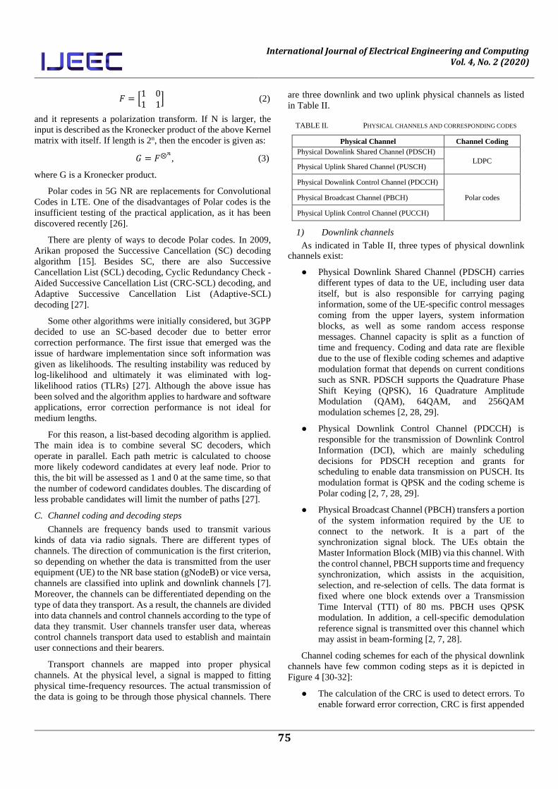
[23]. The encoder is given by Kernel (2) [24]:
International Journal of Electrical Engineering and Computing Vol. 4, No. 2 (2020)
75
𝐹 = [1 01 1
] (2)
and it represents a polarization transform. If N is larger, the
input is described as the Kronecker product of the above Kernel
matrix with itself. If length is 2n, then the encoder is given as:
𝐺 = 𝐹⊗𝑛, (3)
where G is a Kronecker product.
Polar codes in 5G NR are replacements for Convolutional
Codes in LTE. One of the disadvantages of Polar codes is the
insufficient testing of the practical application, as it has been
discovered recently [26].
There are plenty of ways to decode Polar codes. In 2009,
Arikan proposed the Successive Cancellation (SC) decoding
algorithm [15]. Besides SC, there are also Successive
Cancellation List (SCL) decoding, Cyclic Redundancy Check -
Aided Successive Cancellation List (CRC-SCL) decoding, and
Adaptive Successive Cancellation List (Adaptive-SCL)
decoding [27].
Some other algorithms were initially considered, but 3GPP
decided to use an SC-based decoder due to better error correction performance. The first issue that emerged was the
issue of hardware implementation since soft information was
given as likelihoods. The resulting instability was reduced by
log-likelihood and ultimately it was eliminated with log-
likelihood ratios (TLRs) [27]. Although the above issue has
been solved and the algorithm applies to hardware and software
applications, error correction performance is not ideal for
medium lengths.
For this reason, a list-based decoding algorithm is applied.
The main idea is to combine several SC decoders, which
operate in parallel. Each path metric is calculated to choose
more likely codeword candidates at every leaf node. Prior to
this, the bit will be assessed as 1 and 0 at the same time, so that
the number of codeword candidates doubles. The discarding of
less probable candidates will limit the number of paths [27].
C. Channel coding and decoding steps
Channels are frequency bands used to transmit various
kinds of data via radio signals. There are different types of
channels. The direction of communication is the first criterion,
so depending on whether the data is transmitted from the user
equipment (UE) to the NR base station (gNodeB) or vice versa,
channels are classified into uplink and downlink channels [7].
Moreover, the channels can be differentiated depending on the
type of data they transport. As a result, the channels are divided
into data channels and control channels according to the type of
data they transmit. User channels transfer user data, whereas
control channels transport data used to establish and maintain
user connections and their bearers.
Transport channels are mapped into proper physical
channels. At the physical level, a signal is mapped to fitting
physical time-frequency resources. The actual transmission of
the data is going to be through those physical channels. There
are three downlink and two uplink physical channels as listed
in Table II.
TABLE II. PHYSICAL CHANNELS AND CORRESPONDING CODES
Physical Channel Channel Coding
Physical Downlink Shared Channel (PDSCH)
LDPC Physical Uplink Shared Channel (PUSCH)
Physical Downlink Control Channel (PDCCH)
Polar codes Physical Broadcast Channel (PBCH)
Physical Uplink Control Channel (PUCCH)
1) Downlink channels
As indicated in Table II, three types of physical downlink channels exist:
● Physical Downlink Shared Channel (PDSCH) carries
different types of data to the UE, including user data
itself, but is also responsible for carrying paging
information, some of the UE-specific control messages
coming from the upper layers, system information
blocks, as well as some random access response
messages. Channel capacity is split as a function of
time and frequency. Coding and data rate are flexible
due to the use of flexible coding schemes and adaptive
modulation format that depends on current conditions
such as SNR. PDSCH supports the Quadrature Phase
Shift Keying (QPSK), 16 Quadrature Amplitude
Modulation (QAM), 64QAM, and 256QAM
modulation schemes [2, 28, 29].
● Physical Downlink Control Channel (PDCCH) is
responsible for the transmission of Downlink Control
Information (DCI), which are mainly scheduling
decisions for PDSCH reception and grants for
scheduling to enable data transmission on PUSCH. Its
modulation format is QPSK and the coding scheme is
Polar coding [2, 7, 28, 29].
● Physical Broadcast Channel (PBCH) transfers a portion
of the system information required by the UE to
connect to the network. It is a part of the
synchronization signal block. The UEs obtain the
Master Information Block (MIB) via this channel. With
the control channel, PBCH supports time and frequency
synchronization, which assists in the acquisition,
selection, and re-selection of cells. The data format is
fixed where one block extends over a Transmission
Time Interval (TTI) of 80 ms. PBCH uses QPSK
modulation. In addition, a cell-specific demodulation
reference signal is transmitted over this channel which
may assist in beam-forming [2, 7, 28].
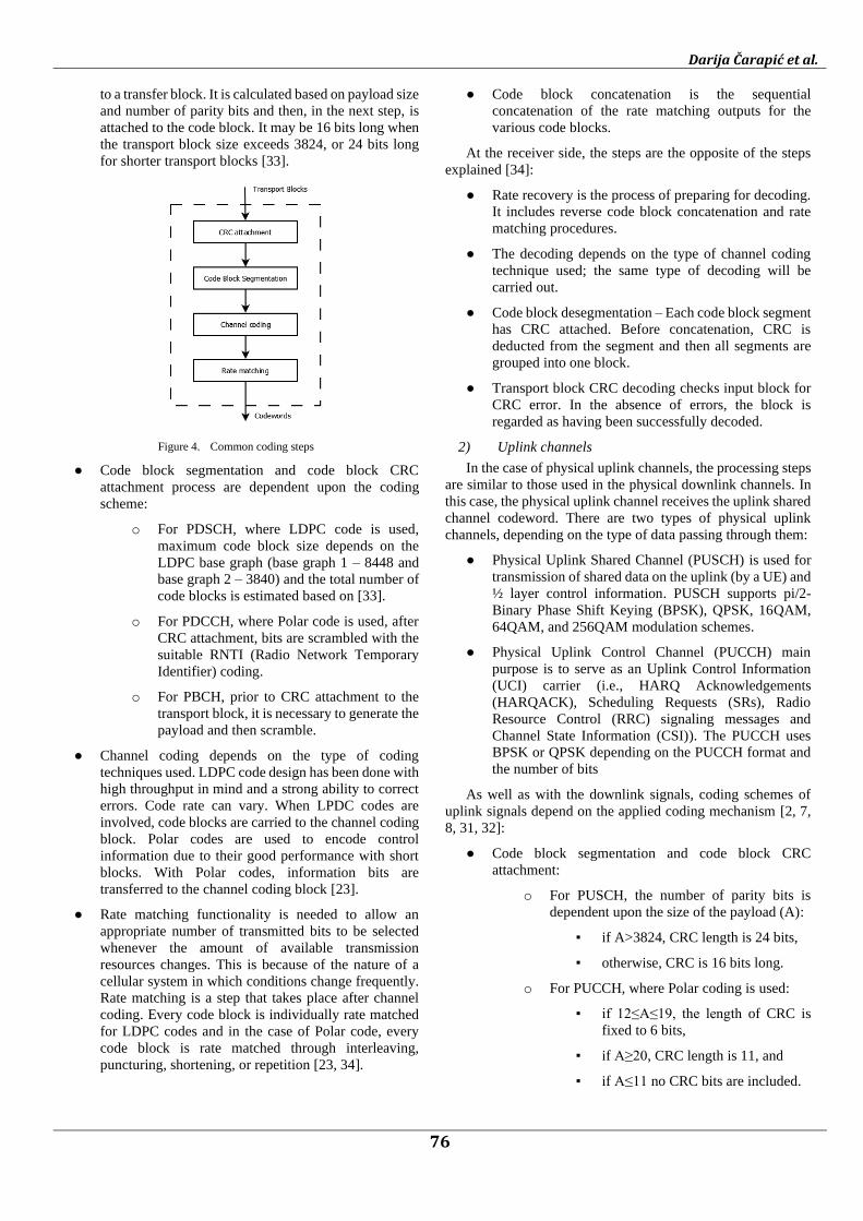
Channel coding schemes for each of the physical downlink
channels have few common coding steps as it is depicted in
Figure 4 [30-32]:
● The calculation of the CRC is used to detect errors. To
enable forward error correction, CRC is first appended
Darija Čarapić et al.
76
to a transfer block. It is calculated based on payload size
and number of parity bits and then, in the next step, is
attached to the code block. It may be 16 bits long when
the transport block size exceeds 3824, or 24 bits long
for shorter transport blocks [33].
Figure 4. Common coding steps
● Code block segmentation and code block CRC
attachment process are dependent upon the coding
scheme:
o For PDSCH, where LDPC code is used,
maximum code block size depends on the
LDPC base graph (base graph 1 – 8448 and
base graph 2 – 3840) and the total number of
code blocks is estimated based on [33].
o For PDCCH, where Polar code is used, after
CRC attachment, bits are scrambled with the
suitable RNTI (Radio Network Temporary
Identifier) coding.
o For PBCH, prior to CRC attachment to the
transport block, it is necessary to generate the
payload and then scramble.
● Channel coding depends on the type of coding
techniques used. LDPC code design has been done with
high throughput in mind and a strong ability to correct
errors. Code rate can vary. When LPDC codes are
involved, code blocks are carried to the channel coding
block. Polar codes are used to encode control
information due to their good performance with short
blocks. With Polar codes, information bits are
transferred to the channel coding block [23].
● Rate matching functionality is needed to allow an
appropriate number of transmitted bits to be selected
whenever the amount of available transmission
resources changes. This is because of the nature of a
cellular system in which conditions change frequently.
Rate matching is a step that takes place after channel
coding. Every code block is individually rate matched
for LDPC codes and in the case of Polar code, every
code block is rate matched through interleaving,
puncturing, shortening, or repetition [23, 34].
● Code block concatenation is the sequential
concatenation of the rate matching outputs for the
various code blocks.
At the receiver side, the steps are the opposite of the steps
explained [34]:
● Rate recovery is the process of preparing for decoding.
It includes reverse code block concatenation and rate
matching procedures.
● The decoding depends on the type of channel coding
technique used; the same type of decoding will be
carried out.
● Code block desegmentation – Each code block segment
has CRC attached. Before concatenation, CRC is
deducted from the segment and then all segments are
grouped into one block.
● Transport block CRC decoding checks input block for
CRC error. In the absence of errors, the block is
regarded as having been successfully decoded.
2) Uplink channels
In the case of physical uplink channels, the processing steps
are similar to those used in the physical downlink channels. In
this case, the physical uplink channel receives the uplink shared
channel codeword. There are two types of physical uplink
channels, depending on the type of data passing through them:
● Physical Uplink Shared Channel (PUSCH) is used for
transmission of shared data on the uplink (by a UE) and
½ layer control information. PUSCH supports pi/2-
Binary Phase Shift Keying (BPSK), QPSK, 16QAM,
64QAM, and 256QAM modulation schemes.
● Physical Uplink Control Channel (PUCCH) main
purpose is to serve as an Uplink Control Information
(UCI) carrier (i.e., HARQ Acknowledgements
(HARQACK), Scheduling Requests (SRs), Radio
Resource Control (RRC) signaling messages and
Channel State Information (CSI)). The PUCCH uses
BPSK or QPSK depending on the PUCCH format and
the number of bits
As well as with the downlink signals, coding schemes of
uplink signals depend on the applied coding mechanism [2, 7,
8, 31, 32]:
● Code block segmentation and code block CRC
attachment:
o For PUSCH, the number of parity bits is
dependent upon the size of the payload (A):
▪ if A>3824, CRC length is 24 bits,
▪ otherwise, CRC is 16 bits long.
o For PUCCH, where Polar coding is used:
▪ if 12≤A≤19, the length of CRC is
fixed to 6 bits,
▪ if A≥20, CRC length is 11, and
▪ if A≤11 no CRC bits are included.
International Journal of Electrical Engineering and Computing Vol. 4, No. 2 (2020)
77
● Channel Coding – as previously stated, the PUSCH will
use the LDPC code, while the Polar code is applied to
PUCCH,
● Rate matching,
● Code block concatenation,
● Multiplexing of data and control information - ensures
that control and data information are mapped to
different modulation symbols.
● Channel interleaver - implements a time-first mapping
of control modulation symbols and frequency-first
mapping of data modulation symbols onto the transmit
waveform.
At the receiver side, the processing stages of PUSCH and
PUCCH correspond to those at the transmitter side.
IV. 5G CHANNEL CODING SCHEMES SIMULATIONS
In this paper, a comparative analysis of LDPC and Polar
coding schemes for different message lengths and code rates
was performed. For simulation purposes, the Additive White
Gaussian Noise (AWGN) channel model serves as a noise
channel. It has been chosen as it is able to imitate the naturally
occurring noise that exists all around us. This noise model is
used to simulate the influence of some natural signals, also
referred to as background noise on a signal. The fundamental
characteristics of the AWGN are stated in its name [15]:
● Additive - The signal on the receiver side corresponds
to the sent signal to which the noise has been added.
● White - The unique power across the entire frequency
range, which does not change with different
frequencies, is the basic idea that noise represents.
● Gaussian – Values close to zero are more likely to
appear because AWGN follows the Gaussian normal
distribution, which means that positive and negative
values are possible.
● Noise – Signal interferences.
The simulations are carried on considering different
message lengths and variable code rates. Shorter messages are
typical in IoT application scenarios while long messages are
associated with broadband data applications. On the other side,
low code rates are practiced in rural areas due to the sparse
distribution of base stations, while in urban regions high coding
rates have been used (due to the ultra-dense population) [34].
All simulations have been performed using MATLAB [31]. As
the quality criterion of a channel code, BER of the coding
schemes is plotted against SNR for different message lengths
(50, 500, 5000, and 50000 bits) and different code rates {1/3,
2/5, ½, 3/5, 2/3, ¾, 4/5, 5/6, 8/9, 9/10}. Message transmission
has been performed using QPSK over the AWGN channel
model which variances are estimated from SNR values. The
transmission parameters were set according to the 5G
numerology. Each simulation was performed for 500 frames
and continued until the BER of 10-5 is achieved.
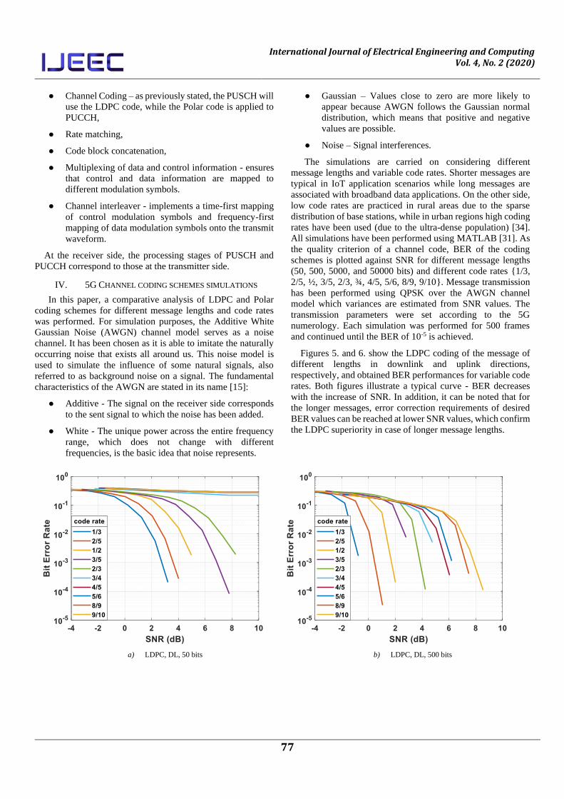
Figures 5. and 6. show the LDPC coding of the message of
different lengths in downlink and uplink directions,
respectively, and obtained BER performances for variable code
rates. Both figures illustrate a typical curve - BER decreases
with the increase of SNR. In addition, it can be noted that for
the longer messages, error correction requirements of desired
BER values can be reached at lower SNR values, which confirm
the LDPC superiority in case of longer message lengths.
a) LDPC, DL, 50 bits b) LDPC, DL, 500 bits
Darija Čarapić et al.
78
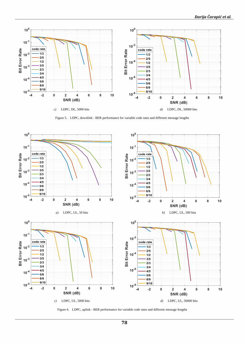
c) LDPC, DL, 5000 bits d) LDPC, DL, 50000 bits
Figure 5. LDPC, downlink - BER performance for variable code rates and different message lengths
a) LDPC, UL, 50 bits b) LDPC, UL, 500 bits
c) LDPC, UL, 5000 bits d) LDPC, UL, 50000 bits
Figure 6. LDPC, uplink - BER performance for variable code rates and different message lengths
International Journal of Electrical Engineering and Computing Vol. 4, No. 2 (2020)
79
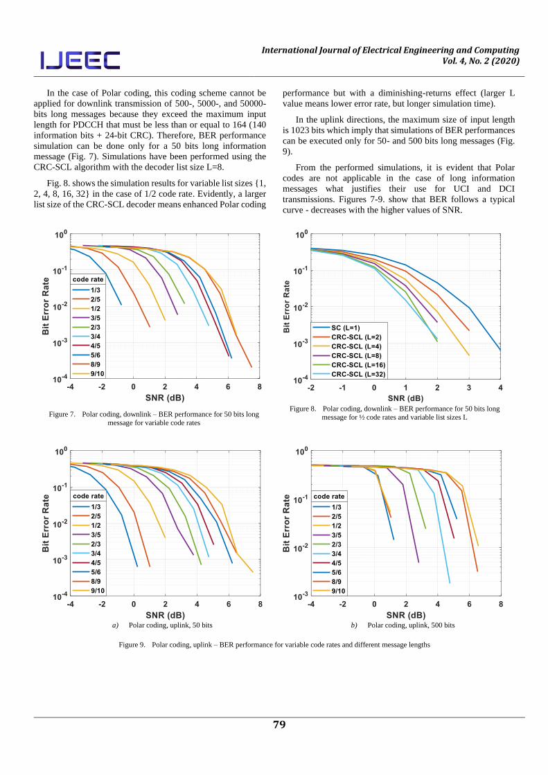
In the case of Polar coding, this coding scheme cannot be
applied for downlink transmission of 500-, 5000-, and 50000-
bits long messages because they exceed the maximum input
length for PDCCH that must be less than or equal to 164 (140
information bits + 24-bit CRC). Therefore, BER performance
simulation can be done only for a 50 bits long information
message (Fig. 7). Simulations have been performed using the
CRC-SCL algorithm with the decoder list size L=8.
Fig. 8. shows the simulation results for variable list sizes {1,
2, 4, 8, 16, 32} in the case of 1/2 code rate. Evidently, a larger
list size of the CRC-SCL decoder means enhanced Polar coding
performance but with a diminishing-returns effect (larger L
value means lower error rate, but longer simulation time).
In the uplink directions, the maximum size of input length
is 1023 bits which imply that simulations of BER performances
can be executed only for 50- and 500 bits long messages (Fig.
9).
From the performed simulations, it is evident that Polar
codes are not applicable in the case of long information
messages what justifies their use for UCI and DCI
transmissions. Figures 7-9. show that BER follows a typical
curve - decreases with the higher values of SNR.
Figure 7. Polar coding, downlink – BER performance for 50 bits long
message for variable code rates
Figure 8. Polar coding, downlink – BER performance for 50 bits long
message for ½ code rates and variable list sizes L
a) Polar coding, uplink, 50 bits b) Polar coding, uplink, 500 bits
Figure 9. Polar coding, uplink – BER performance for variable code rates and different message lengths
Darija Čarapić et al.
80
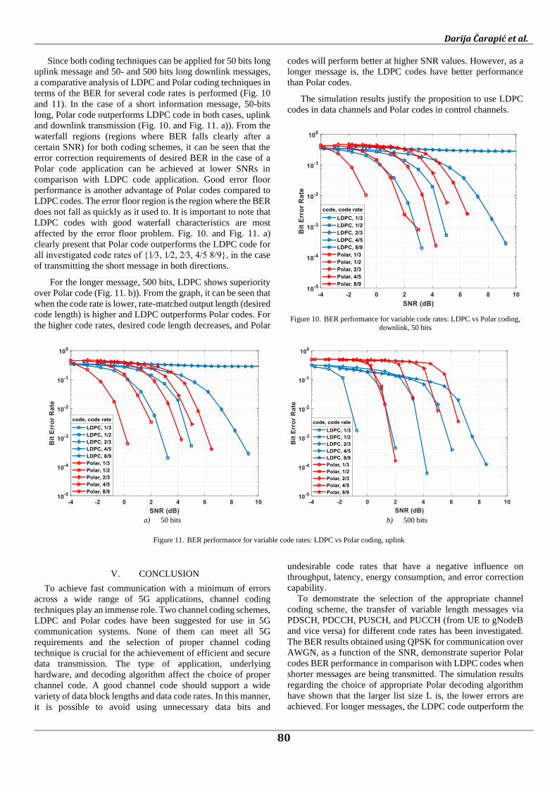
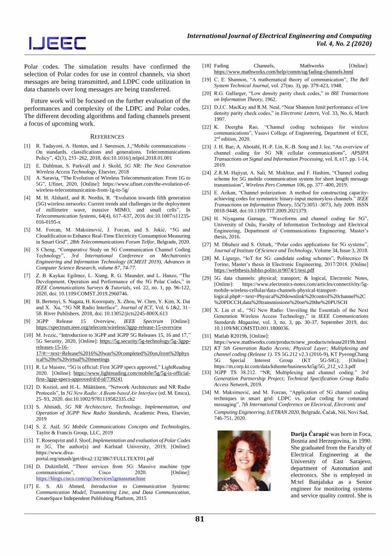
Since both coding techniques can be applied for 50 bits long
uplink message and 50- and 500 bits long downlink messages,
a comparative analysis of LDPC and Polar coding techniques in
terms of the BER for several code rates is performed (Fig. 10
and 11). In the case of a short information message, 50-bits
long, Polar code outperforms LDPC code in both cases, uplink
and downlink transmission (Fig. 10. and Fig. 11. a)). From the
waterfall regions (regions where BER falls clearly after a
certain SNR) for both coding schemes, it can be seen that the
error correction requirements of desired BER in the case of a
Polar code application can be achieved at lower SNRs in
comparison with LDPC code application. Good error floor
performance is another advantage of Polar codes compared to
LDPC codes. The error floor region is the region where the BER
does not fall as quickly as it used to. It is important to note that
LDPC codes with good waterfall characteristics are most
affected by the error floor problem. Fig. 10. and Fig. 11. a)
clearly present that Polar code outperforms the LDPC code for
all investigated code rates of {1⁄3, 1⁄2, 2⁄3, 4/5 8/9}, in the case
of transmitting the short message in both directions.
For the longer message, 500 bits, LDPC shows superiority
over Polar code (Fig. 11. b)). From the graph, it can be seen that
when the code rate is lower, rate-matched output length (desired
code length) is higher and LDPC outperforms Polar codes. For
the higher code rates, desired code length decreases, and Polar
codes will perform better at higher SNR values. However, as a
longer message is, the LDPC codes have better performance
than Polar codes.
The simulation results justify the proposition to use LDPC
codes in data channels and Polar codes in control channels.
Figure 10. BER performance for variable code rates: LDPC vs Polar coding,
downlink, 50 bits
a) 50 bits b) 500 bits
Figure 11. BER performance for variable code rates: LDPC vs Polar coding, uplink
V. CONCLUSION
To achieve fast communication with a minimum of errors
across a wide range of 5G applications, channel coding
techniques play an immense role. Two channel coding schemes,
LDPC and Polar codes have been suggested for use in 5G
communication systems. None of them can meet all 5G
requirements and the selection of proper channel coding
technique is crucial for the achievement of efficient and secure
data transmission. The type of application, underlying
hardware, and decoding algorithm affect the choice of proper
channel code. A good channel code should support a wide
variety of data block lengths and data code rates. In this manner,
it is possible to avoid using unnecessary data bits and
undesirable code rates that have a negative influence on
throughput, latency, energy consumption, and error correction
capability.
To demonstrate the selection of the appropriate channel
coding scheme, the transfer of variable length messages via
PDSCH, PDCCH, PUSCH, and PUCCH (from UE to gNodeB
and vice versa) for different code rates has been investigated.
The BER results obtained using QPSK for communication over
AWGN, as a function of the SNR, demonstrate superior Polar
codes BER performance in comparison with LDPC codes when
shorter messages are being transmitted. The simulation results
regarding the choice of appropriate Polar decoding algorithm
have shown that the larger list size L is, the lower errors are
achieved. For longer messages, the LDPC code outperform the
International Journal of Electrical Engineering and Computing Vol. 4, No. 2 (2020)
81
Polar codes. The simulation results have confirmed the
selection of Polar codes for use in control channels, via short
messages are being transmitted, and LDPC code utilization in
data channels over long messages are being transferred.
Future work will be focused on the further evaluation of the
performances and complexity of the LDPC and Polar codes.
The different decoding algorithms and fading channels present
a focus of upcoming work.
REFERENCES
[1] R. Tadayoni, A. Henten, and J. Sørensen, J.,“Mobile communications –
On standards, classifications and generations. Telecommunications Policy”, 42(3), 253–262, 2018, doi:10.1016/j.telpol.2018.01.001
[2] E. Dahlman, S. Parkvall and J. Skold, 5G NR: The Next Generation Wireless Access Technology, Elsevier, 2018
[3] A. Saravia, “The Evolution of Wireless Telecommunication: From 1G to
5G”, Ufinet, 2020, [Online]: https://www.ufinet.com/the-evolution-of-wireless-telecommunication-from-1g-to-5g/
[4] M. H. Alsharif, and R. Nordin, R. “Evolution towards fifth generation (5G) wireless networks: Current trends and challenges in the deployment
of millimetre wave, massive MIMO, and small cells”, In
Telecommunication Systems, 64(4), 617–637, 2016 doi:10.1007/s11235-016-0195-x
[5] M. Forcan, M. Maksimović, J. Forcan, and S. Jokić, “5G and
Cloudification to Enhance Real-Time Electricity Consumption Measuring in Smart Grid”, 28th Telecommunications Forum Telfor, Belgrade, 2020.
[6] S Cheng, “Comparative Study on 5G Communication Channel Coding
Technology”, 3rd International Conference on Mechatronics
Engineering and Information Technology (ICMEIT 2019), Advances in Computer Science Research, volume 87, 74-77.
[7] Z. B. Kaykac Egilmez, L. Xiang, R. G. Maunder, and L. Hanzo, “The
Development, Operation and Performance of the 5G Polar Codes,” in IEEE Communications Surveys & Tutorials, vol. 22, no. 1, pp. 96-122, 2020, doi: 10.1109/COMST.2019.2960746.
[8] B. Bertenyi, S. Nagata, H. Kooropaty, X. Zhou, W. Chen, Y. Kim, X. Dai and X. Xu, “5G NR Radio Interface”, Journal of ICT, Vol. 6 1&2, 31–58. River Publishers. 2018, doi: 10.13052/jicts2245-800X.613
[9] 3GPP Release 15 Overview, IEEE Spectrum [Online]: https://spectrum.ieee.org/telecom/wireless/3gpp-release-15-overview
[10] M. Ivezic, “Introduction to 3GPP and 3GPP 5G Releases 15, 16 and 17,” 5G Security, 2020, [Online]: https://5g.security/5g-technology/5g-3gpp-
releases-15-16-
17/#:~:text=Release%2016%20was%20completed%20on,from%20phys
ical%20to%20virtual%20meetings
[11] R. Le Maistre, “5G is official: First 3GPP specs approved,” LightReading 2020. [Online]: https://www.lightreading.com/mobile/5g/5g-is-official-first-3gpp-specs-approved/d/d-id/739241
[12] D. Koziol, and H.-L. Määttänen, “Network Architecture and NR Radio Protocols”, In 5G New Radio: A Beam‐based Air Interface (ed. M. Enscu), 25–93, 2020. doi:10.1002/9781119582335.ch2
[13] S. Ahmadi, 5G NR Architecture, Technology, Implementation, and
Operation of 3GPP New Radio Standards, Academic Press, Elsevier, 2019
[14] S. Z. Asif, 5G Mobile Communications Concepts and Technologies, Taylor & Francis Group, LLC, 2019
[15] T. Rosenqvist and J. Sloof, Implementation and evaluation of Polar Codes
in 5G, The author(s) and Karlstad University, 2019, [Online]:
https://www.diva-
portal.org/smash/get/diva2:1323867/FULLTEXT01.pdf
[16] D. Dukinfield, “Three services from 5G: Massive machine type communications”, Cisco 2020. [Online]: https://blogs.cisco.com/sp/3services5gmassmachine
[17] E. S. Ali Ahmed, Introduction to Communication Systems: Communication Model, Transmitting Line, and Data Communication, CreateSpace Independent Publishing Platform, 2015
[18] Fading Channels, Mathworks [Online]: https://www.mathworks.com/help/comm/ug/fading-channels.html
[19] C. E. Shannon, “A mathematical theory of communication”, The Bell System Technical Journal, vol. 27(no. 3), pp. 379-423, 1948.
[20] R.G. Gallarger, “Low density parity check codes,” in IRE Transactions on Information Theory, 1962.
[21] D.J.C. MacKay and R.M. Neal, “Near Shannon limit performance of low density parity check codes,” in Electronic Letters, Vol. 33, No. 6, March 1997.
[22] K. Deergha Rao, “Channel coding techniques for wireless communications”, Vasavi College of Engineering, Department of ECE, 2nd edition, 2020.
[23] J. H. Bae, A. Abotabl, H.-P. Lin, K.-B. Song and J. lee, “An overview of
channel coding for 5G NR cellular communications”, APSIPA
Transactions on Signal and Information Processing, vol. 8, e17, pp. 1-14, 2019.
[24] Z.R.M. Hajiyat, A. Sali, M. Mokhtar, and F. Hashim, “Channel coding
scheme for 5G mobile communication system for short length message transmission”, Wireless Pers Commun 106, pp. 377–400, 2019.
[25] E. Arikan, “Channel polarization: A method for constructing capacity-achieving codes for symmetric binary-input memoryless channels.” IEEE
Transactions on Information Theory, 55(7):3051–3073, July 2009. ISSN 0018-9448. doi:10.1109/TIT.2009.2021379.
[26] H. Niyagama Gamage, “Waveforms and channel coding for 5G”,
University of Oulu, Faculty of Information Technology and Electrical
Engineering, Department of Communications Engineering. Master’s thesis, 2016.
[27] M. Dhuheir and S. Ozturk, “Polar codes applications for 5G systems”, Journal of Institute Of Science and Technology, Volume 34, Issue 3, 2018.
[28] M. Ligurgo, “IoT for 5G: candidate coding schemes”, Politecnico Di Torino, Master’s thesis in Electronic Engineering, 2017/2018. [Online] https://webthesis.biblio.polito.it/9074/1/tesi.pdf
[29] 5G data channels: physical; transport; & logical, Electronic Notes, [Online]: https://www.electronics-notes.com/articles/connectivity/5g-
mobile-wireless-cellular/data-channels-physical-transport-
logical.php#:~:text=Physical%20downlink%20control%20channel%2C%20PDCCH,data%20transmissions%20on%20the%20PUSCH
[30] X. Lin et al., “5G New Radio: Unveiling the Essentials of the Next Generation Wireless Access Technology,” in IEEE Communications
Standards Magazine, vol. 3, no. 3, pp. 30-37, September 2019, doi: 10.1109/MCOMSTD.001.1800036.
[31] Matlab R2019b, [Online]:
https://www.mathworks.com/products/new_products/release2019b.html
[32] KT 5th Generation Radio Access; Physical Layer; Multiplexing and channel coding (Release 1). TS 5G.212 v2.3 (2016-9), KT PyeongChang
5G Special Interest Group (KT 5G-SIG); [Online]:
https://m.corp.kt.com/data/kthome/business/kt5g/5G_212_v2.3.pdf [33] 3GPP TS 38.212. “NR; Multiplexing and channel coding.” 3rd
Generation Partnership Project; Technical Specification Group Radio Access Network, 2019.
[34] M. Maksimović, and M. Forcan, “Application of 5G channel coding
techniques in smart grid: LDPC vs. polar coding for command messaging”, 7th International Conference on Electrical, Electronic and
Computing Engineering, IcETRAN 2020, Belgrade, Čačak, Niš, Novi Sad, 746-751, 2020.
Darija Čarapić was born in Foca,
Bosnia and Herzegovina, in 1990.
She graduated from the Faculty of
Electrical Engineering at the
University of East Sarajevo,
department of Automation and
electronics. She is employed in
M:tel Banjaluka as a Senior
engineer for monitoring systems
and service quality control. She is
Darija Čarapić et al.
82
currently working on a master
thesis whose topic is the 5G
network.
Mirjana Maksimović is an associate professor at Faculty of Electrical Engineering, University of East Sarajevo, Bosnia and Herzegovina. Her current research and teaching interests extend to a range of topics in Telecommunications, Automation, Electronics and Computer Science. She has published one book and more than 100 papers in national and international journals and conferences.