Embed Size (px)
Citation preview

HAL Id: hal-01624015https://hal.archives-ouvertes.fr/hal-01624015
Preprint submitted on 5 Nov 2017
HAL is a multi-disciplinary open accessarchive for the deposit and dissemination of sci-entific research documents, whether they are pub-lished or not. The documents may come fromteaching and research institutions in France orabroad, or from public or private research centers.
L’archive ouverte pluridisciplinaire HAL, estdestinée au dépôt et à la diffusion de documentsscientifiques de niveau recherche, publiés ou non,émanant des établissements d’enseignement et derecherche français ou étrangers, des laboratoirespublics ou privés.
A Comparative Study Between ABS and Disc BrakeSystem Using Finite Element Method
Saleh Mobasseri, Mohammad Mobasseri
To cite this version:Saleh Mobasseri, Mohammad Mobasseri. A Comparative Study Between ABS and Disc Brake SystemUsing Finite Element Method. 2017. �hal-01624015�

A Comparative Study between ABS and Disc Braking System Using
Finite Element Method
Saleh Mobasseri1,*, Mohammad Mobasseri2,3
1,* Young Researchers and Elite Club, Marvdasht Branch, Islamic Azad University, Marvdasht, Iran.
2 Department of Mechanical Engineering, Markazi Science and Research Branch, Islamic Azad
University, Arak, Iran
3 Department of Mechanical Engineering, Arak Branch, Islamic Azad University, Arak, Iran
ABSTRACT
This paper, refers to the history of the rise of brake system and describe its importance in passenger’s
lives. An Anti-lock braking system (ABS), is the safety of vehicle systems to achieve maximum braking
and decelerating in terms of increasing the stability and balance of the car and reduces the braking distance
is designed. The performance of disc brake system and the ABS controller are also compared with each
other by the kinetic analysis of the braking system and evaluate the impact of each parameters are checked
on the vehicle stopping distance. In this study, we use Finite Element software Abaqus 6.14 and we found
some interesting result, such as the effect of temperature on the performance and braking system
efficiency. The Anti-lock braking system (ABS) is one of the most important feature that affect on vehicle
safety and for this research much efforts have been made to improve this system. One of the aims of this
paper is to compare system performance between disc brake system and ABS with the help of modeling
in different conditions (rainy, snowy, etc).
KEYWORDS: Anti-lock braking system (ABS), Car Stability, Finite Element Simulation, Stopping
Distance, Tire-Slip.
* For correspondence (E-mail: [email protected])

1. Introduction
Due to the advancement of technology and increase the number of automobiles, some people prefer to
travel by private cars. This approach leads to increase the volume of vehicles traffic in urban and inter the
city routes and increase fuel consumption [1,2].
Reducing of stopping distances and increasing the car stability, are the most important factors in the
reducing number of accidents. These two factors are depended to coefficient friction between automobile
tires and the ground. Due to the advancement of technology and sensors in the 80's, use of these
technologies in automobiles are began. The biggest disadvantage of conventional brakes is that the driver
can't precisely control the amount of brake torque applied to the wheels. If there is no precise information
on road conditions, sudden and excessive pressing the brake pedal will lock the wheels. To counter the
risks of collisions and reduce accidents, control the automobile and driving in different weather conditions,
reduced stopping distances, increase stability and steering, avoid locking the brakes, development of new
system like ABS, VDC, EBD, ESP is necessary, so that up to 40% of accidents can be avoided. Since 80's,
the Anti-lock braking system (ABS) in automobiles, increased by using a safety airbag [3]. The ABS, try
to keep the maximum longitudinal and lateral tire friction coefficient. Thereby, achieving the minimum
distance to stop the vehicle, increasing car's stability. The parameters that influence of the brake process:
The force applied by the driver's foot on the brake pedal, ambient air pressure and air pressure in the tire,
tire quality, friction between the tire and the ground, car speed at the beginning of the braking process,
orifices discharge coefficient, the external force acting on the vehicle body, how to distribute the weight
of the car on wheels, type of pads, road conditions and tire, brake torque exerted on the tire.
2. Types of braking system:
2.1) Disc Brake System: Research, design and manufacture of disc brake system in England began in
1890 and was registered in 1902 in Birmingham by “Frederick William Lanchester” and the modified
model was designed in 1949.
The way of disc brakes operation: Power of driver’s foot enters the booster and then, is reinforced the
power of driver’s foot by the pressure difference created on both sides of the diaphragm; In fact, the force
of the brake pedal and booster, brake circuit, creates hydraulic pressure and the pressure generated by the
hydraulic line is transferred to the wheel's cylinder and turns into the braking force and in accordance with
the wheel's piston area, a force is exerted to the wheel.
In the time of booster activation, the diaphragm in front of the air and the vacuum motor is attached [4].
The duty of booster is to increase the power of the driver's foot of 4 to 6 times.

Figure 1: Master Cylinder and Vacuum Booster
2.2) Kinds of braking modes:
a) The optimal mode of braking (Torque brake = Torque frictional) When the braking torque is equal to the
friction torque.
b) Non-Optimal braking mode:
The first mode: When the brake of torque is greater than the frictional torque: (Torque brake ˃ Torque frictional)
In this situation, due to the lack of braking force, stopping distance of the car will be increase.
The second mode: Torque of brake, is greater than friction torque.
(Torque brake˂ Torque frictional)
In this situation, the wheels are locked and the car will be in a state of imbalance.
Disc brake components are Brake lent, Caliper, Rotor.
3. Simulation
As the simulation results of disc brake system indicate, due to the high friction, the temperature is
increased and ultimately, the efficiency of braking system will be reduced.
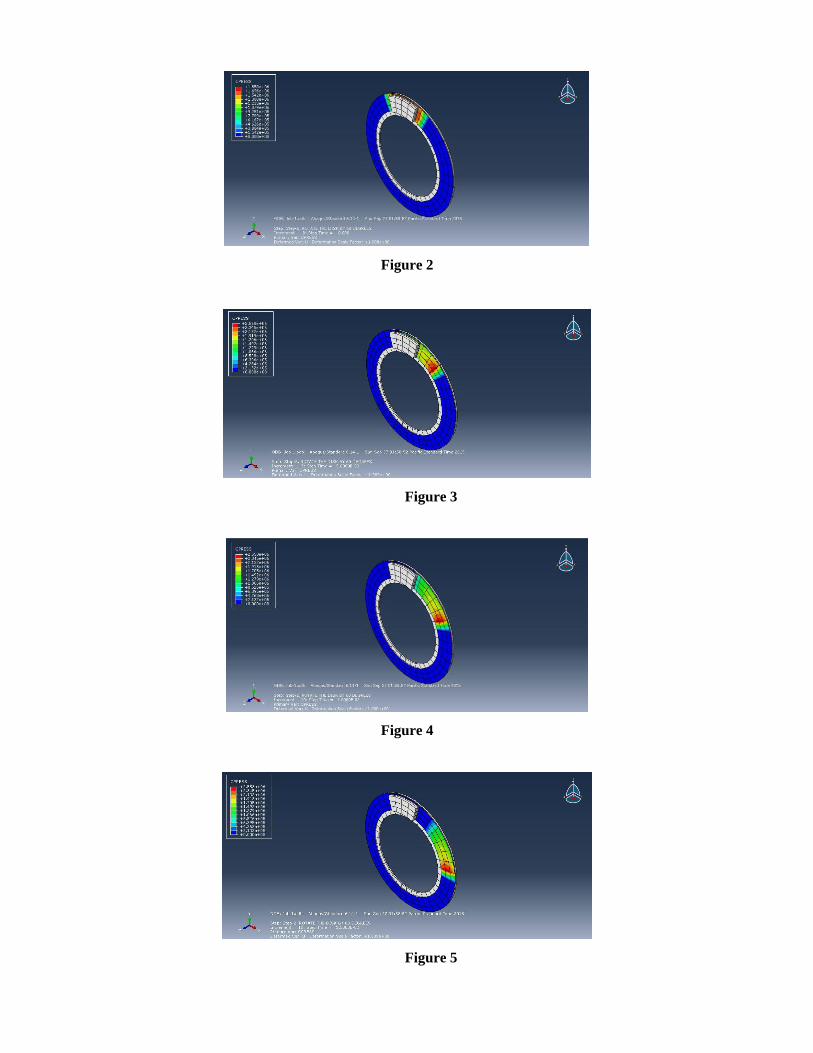
Figure 2
Figure 3
Figure 4
Figure 5

4. The disadvantages of disc brake system:
1) Low-speed performance when pressing the brake pedal.
2) High brake stopping distance.
3) Slip vehicle on slippery distances.
4) Imbalance in the car.
5) Sensitive to dust and moisture.
6) Reduced brake system efficiency because of the rising temperatures.
5) Anti-lock braking system (ABS): This system is an electronic device when the brake with hydraulic
pressure control and associated with disc or drum pads, hold, hang up and rapid. The result of continued
rapid and repeat this process is destroying the locking in brakes system. The importance of this kind of
brakes will appear more, on wet and slippery surfaces or braking at high speeds. The first time was raised
in 1905 in Germany. For the first time was mechanically used in the aircraft in 1930 and at the same time,
many changes occurred in the aviation industry through the development of this system [5,6]. In 1969, the
first ABS for cars were installed only on the rear wheels, was produced at Ford Motor Company and the
modern ABS with electronic control unit was designed and built in 1976 by the "Daimler-Benz" and
"Bosch company" [7].
All over the world, researcher in designing field, have done many kind of researches on the ABS system
and achieved different results. The most important of them are:
Gerdes et al. have been studying and modeling the brake system [8]. Most of their studies have been
modeling the car’s vacuum booster. The main feature of this model is the static model of control boost
valve with a dynamic of the air inlet. WU et al. have don modeling the brake system in more detail than
previous studies [9]. The important parts of their paper, are designing PWM sliding mode controller and
evaluation of controller which was designed in experimental test. Khan et al. have done modeling and
simulation the boosters. The method used for modeling and simulation of the booster has Bond Graph
[10]. So, in their paper, the governing equations of the system are not available, and modeling of hydraulic
of the ABS system has not performed. Hu et al. have done modeling and simulation the features of main
cylinder of the brake system in static model [11]. Their study is based on the main cylinder brake system.
At first, they extract components of the static model of the main cylinder and their effort was to utilize the
friction force between the piston and the cylinder in calculations. Harifi et al. just provided a dynamic
model of the vehicle body and tires [12]. In their paper, the modeling of all components of the ABS were

ignored. Kuang et al. modeled the dynamic of hydraulic brake systems about a vehicle for active controller
systems of the car [13]. The name of method which used in their paper, is Bond Graph method. Soliman
et al. have been created an integrated controller between the active suspension system and the ABS system
using Fuzzy-Logic control theories to improve braking performance [14]. The simulation result of their
research obtained show that the active and ABS with integrated controlled reduces the braking time and
distance in the range from 3% to 5% compared with the same without integrated controller.
Kaldas et al. have been developed a control system that combines suspension and brake system [15]. The
simulation result of their work, demonstrates that using Fuzzy-Logic control with controlled suspension
systems and the ABS provides a significant improvement in truck ride comfort and braking performance
under different driving conditions. Soliman and Kaldas, they have been studied the influence of vehicle
initial speed and tire-road friction coefficient is investigated [16]. The result showed that, using Fuzzy-
Logic Control in ABS, improved the braking performance than the conventional ABS. Kaldas and
Soliman, showed the effect of investigating the influence of the preview control of the active suspension
on the vehicle ride and braking performance [17]. The results are generated in the time domain to simulate
the vehicle response during braking, while wheels are subjected to vertical road input. Emil Precup et al.
in their research, suggest a synergy of Fuzzy-Logic and nature-inspired optimization in terms of the nature-
inspired optimal tuning of the input membership functions of a class of Takagi-Sugeno-Kang (TSK) fuzzy
models dedicated to ABS [18]. The objective of Qiang Wang et al. is to minimize total impact energy by
determining the desired braking force [19].
5.1) Introduction ABS: In this system, the amount of braking force on each wheel can be different.
Therefore, the wheel which has less speed than the other wheel, proportionally, the pressure of brake fluid
is reduced. The pressure, reduction is across-sectional and continues until wheel’s spin to be equal. The
ABS start to control the brake system up to 6 km/h and if for any reason getting problem, the ABS switched
off and the brake operate as normal [9,20]. The ABS include electronic controls, a solenoid (for releasing
and re-applied brake pressure) and the sensor of speed to the wheel [21]. Modes of the ABS performance:
The vehicle’s mainframe with sensors in each wheel, checks the wheel’s speed during braking. If the
rotational speed of the wheel’s different than other wheels, the main frame changes the pressure inside the
cylinder with a required command to the electronic brake valve that makes change in amount of braking
force applied to the wheels and vehicles wheel is getting out of the critical situation. So the possibility of
locking the wheel is decrease. The above process, are continuously done with high speed so that the
process is repeated in per minute between 15 to 20 times. In ABS, we must know when the wheels are

slipping or locked. Speed sensors which have been installed on each wheel, give us this information. By
recognizing slip or locking of the wheels, controller commands the modulator to reduce the braking torque
to prevent the wheels from locking.
Slip is [9]:
V
RV W
= The amount of slip between tire and car
V = Vehicle speed
ω = Tire rotation speed
R = The radius of the wheel
In this case, the wheels of the car are locked. The below figure shows an example of friction sliding friction
coefficient curves for the road conditions [22].
Figure 6: Coefficient of friction on the slip curve [22]
5.2) Types of the Anti-lock braking system (ABS): Generally, the ABS based on the number of
channels (number of valves that are separately controlled) and the number of speed sensors, divided to
the various categories that the most important of them are mentioned below:
1- The ABS with 4 channel and 3 speed sensor: This case, is extremely functional in trucks and vans
with 4 Anti-lock wheels.
2- The ABS with 3 channels and 3 speed sensor: This case, more applications are in the trucks and vans
with 4 Anti-lock wheels and on the front wheels, a sensor and the valve is designed; But for the rear
wheel, there is only one sensor and the valve which is located on the rear axle. In fact, for each front
wheel, is a separate controller so more braking force be applied to the front wheels. One of the
disadvantages of this case (three-channel system with three sensor), is the rear-wheel ABS, locked and

therefore, using this system may lock the rear wheels while braking that reduces the effectiveness of the
brake and the car balance.
3- The ABS with a channel and sensor: This system exists in vans and trucks which their rear axle is
Anti-lock. The control valve for each wheel and speed sensor is located on the rear axle. In this way, it is
possible lock the wheels during the braking.
The main part of the Anti-Lock System: In ABS, there are 4 main sections:
1- Sensor of speed: The ABS must know when the car wheel, being locked up. Speed sensors, provide
the necessary information for his system.
2- Valves: In the brake pipe, 1 valve is existing.
6. Modeling:
6.1) Modeling and description of some of the components of braking system is as follow:
6.1.1) Modeling of pedal: Brake pedal, is the first component of the brake system, which is reinforced the
force of driver’s foot, is supported by the following formula:
Figure 7: The pedal and the forces on the pedal
Fpedal = Fa
bin
The maximum force is applied to the brake pedal, for women is about 445 Newton and for men is 823
Newton [24].
6.1.2) Booster: As we explained in the disc brake section, the duty of booster is Quadruple Sextuple the
force of the driver’s foot [4].
When the booster ia activated, the following relation are dominate:
Fbooster = Fd + Fpedal – Frs
Fbooster = External power booster
Fd = The pressure difference between the 2 sides of the diaphragm

Frs= Return spring force booster
Therefore, the amount of Fd can be calculated as follows:
Fd = (Pa–Pν )Ad
Pν = Pressure on the diaphragm
Pa= Pressure behind the diaphragm
Ad= The effective area
Apply the force
Booster has 3 modes are: Hold Force
Release the force
So the amount of Fd is different in each of these modes. Three considered cases can be written as following
equation:
Fpedal < Frelease Release
Frelease ≤ Fpedal ≤ F apply Hold
Fapply ≤ Fpedal Apply
Figure 8: States of the Booster [7]
6.1.3) Hydraulic section: Most important point of Anti-lock braking system is controlling the amount of
the pressure of brake hydraulic fluid behind the piston caliper or wheel cylinders.
The section of ABS hydraulic system, begins from the main cylinder and continues to the wheel cylinder.
Vehicle dynamics modeling: The following shape shows a free diagram of the car which is braking.

Figure 9: Free diagram of the braking vehicle [30]
By using Newton’s second law we have:
Fb = The process of brake force in braking
M = The mass of vehicle
Fbf = Brake force rear wheel
Da = Air resistance force
Rxf = Rolling resistance force of front wheels
Rxr = Rolling resistance force of the rear wheels
W = The slope of the road force
Rolling resistance force is as follows [23]:
Rx = Rxf + Rxr = (Wf + WR) fr
Wf = Vertical force applied to the front tire
WR = Vertical force applied to the rear tire
Rw = The radius of the wheel
fr = The factor of rolling resistance
Vertical force exerted on the front and rear wheels are from the following equation:
M
WRRDFF
M
Fa
xrxfabrbfbx
sin

H = The height of the center of gravity of the vehicle from the road
ax = Longitudinal vehicle acceleration
M = Vehicle mass
Lf = Distance from the center of front wheel to the center of gravity
Lr = Distance from the center of front wheel to the center of mass
Ha = Effective height of the air force
Da = Air resistance force
6.2) Tire modeling:
Generally, tire’s models can be divided into 2 categories, static model and dynamic models. Static friction
models are used in terms of linear and angular velocities. Dynamic models represent the actual behavior
of the tire at the time changing the speed [24]. The quality of the tire and asphalt paving plays an important
role in maintaining the car’s balance. An appropriate road for a car is the broadband to control the car in
the road. Control of the vehicle on the road depends on the wheel sticking to the ground and the other
vehicle characteristics such as a height of the center of the wheel, axle length and mass distribution in the
automotive and etc. In simulation and analysis of vehicle, dynamics adhesions is one of the most important
parameters that must be considered in the design of the suspension.
The low graphs show the change in the coefficient of friction on the surface of the slide [25]:
)(2)(2
cos
)(2)(2
sin
)(2)(2
cos
)(2)(2
sin
rf
aa
rf
f
rf
x
rfr
rf
aa
rf
r
rf
x
rff
LL
HD
LL
WL
LL
HMa
LL
WHW
LL
HD
LL
WL
LL
HMa
LL
WHW

Figure 10: Longitudinal tire slip for different road surfaces [29]
Figure 11: Tire friction curve
7) The analysis of car stop in making brake is divided into 2 categories:
7.1) Kinematic analysis: kinematic situation of the car which can be analyzed at any time by 4 parameters
as follows: speed, acceleration, distance and time. We assume the car is moving at a constant speed
V1.When the driver sees an obstacle in the path until the brake pedal is pressed, takes as much as “t”,
which is called as “driver reaction time”. This time is usually between 0.75 to 1.5 seconds [26]. After
applying a force on the brake pedal, the linings are about 0.1 to 0.2 seconds connected to the disc with a
time lag. After passing “t”, decelerating the car begins to increase until it reaches the maximum amount
and then remains constant till its full stop. In the range of “t”, acceleration is changed and at any moment
can be calculated.
7.2) Kinetic analysis: The total rolling resistance and static friction, reduce car’s speed when using the
brake. When the brakes are locked, the tires slip on the road surface and thus can’t effectively reduce car
speed. The maximum braking force occurs when there is about 11% of slip between the wheels and the
road. This issue is used to increase the efficiency of ABS [24]. To kinetic analysis of the brake system and

optimization of its perform, the most important parameters are: Vehicle speed, stopping distance, the force
on the wheel, the force applied to the brake pedal, the diameter of main cylinder and the cylinder of the
wheels, the force on the wheel, the coefficient of friction between the surface in contact like the surface
of lining with disc, the car’s holder force.
7.3) The advantages of ABS: Reduce stopping distance, increase vehicle stability and steering, reduce
the amount of tire’s vibration, reduce the torsion of tire, and prevent the diversion of car on slippery roads
during heavy braking.
7.4) The disadvantages of ABS: This system along with its advantages, has more disadvantages of the
brake system, include:
a) Rapid and continuous replication of connecting and disconnecting of the brake way by ABS, causing
the loss of the blocking or locking the brakes.
b) In ABS, serve noise is heard during the braking on extremely slippery surfaces.
c) This system on soft surface (such as snow or sand) doesn’t have a good performance. One of the cause
of increasing the stopping distance in these situations is that, when the driver of vehicles with conventional
braking system (disc brake), presses the brake pedal, because of locking wheels, some of snow or sand
are collected in the wheels. The same applies helps to increase braking power.
d) On the surface which is the combination of asphalt and snow, the tire will swerve to asphalt.
e) Given that this ABS in composed by more components than the brake disc, its repair and maintenance
cost are higher.
Table 1: Summary of the deceleration values [27]:
Road surface Braking [m/s2] Acceleration [m/s2]
Ice
Snow
Table 2: Summary of braking decoration on the icy surface [28]:
Tire type ABS Surface
temperature [˚C]
Ambient
temperature [˚C]
Braking
deceleration
Winter Yes -5.4 05.9 2.65-1.47
No 2.06-1.47
Summer Yes -5.2 -3.1 1.96-1.28
No 1.57-1.47

8. Conclusion
According to the modeling that carried out in this paper and researcher’s studies in the field of the
accidents which lead to life and financial casualties, it was determined that serve or uncontrolled vehicles
are around the vertical axis is the main cause of these accidents. In the perspective of vehicle dynamic,
such intensive rotational motion is caused by the instability of the lateral dynamic of the car. The other
important parameters that effect on the process of stopping the vehicle, can refer to the following: The of
driver’s feet, the geometry of the pedal. The amount of engine’s vacuum, coefficient of orifices discharge,
opening and closing properties of electronic valves, the effective radius of the tire, radius of brake discs,
type and quality the tire, the amount of the tire’s tread, road type, the amount of vertical load on the wheels,
specification of hydraulic oil of brake, the amount of existence air in the hydraulic oil of the brake. The
hydraulics of ABS, with a time lag of about 0.5 seconds from pressing the pedal to start reducing the
vehicle’s speed that the above factors are effective in changing this time duration. During pressing the
brake pedal, pressure of hydraulic oil reaches about 60 times. Based on the presented entries in the paper
and the importance of stopping the car in different situations by keeping the balance, the performance of
ABS can be summarized as follows:
1) These systems by preventing the wheels from locking, increasing the car’s steering.
2) In some special circumstances, such as sandy or snowy road, the cars which has the ABS, their distance
to stop rises than the vehicles with conventional brakes.
3) The mass of the vehicle does not have any special effect on the stopping distances of the car and it can
only effect on the force of brake pedal, so that by increasing the mass of the vehicle, the required force is
increasing to lock the wheels.
4) The ABS prevention of temperature rises during this process because the type of designing ABS.
References:
[1] Mobasseri, S., & Soltani, H., (2013). Impact of driving style on fuel consumption. Nature and
Science, (11), 87.
[2] Mobasseri, S., & Soltani, H., (2014). Traffic noise and it's measurement methods. Advances in
Environmental Biology, 1277-1285.
[3] Petkov, Nikolay. "Nanoporous hosts for the encapsulation of conductive nanostructured materials."
PhD diss., lmu, 2004.

[4] Limpert, Rudolf. Brake design and safety. 1999.
[5] Hattwig, Peter. Synthesis of ABS hydraulic systems. No. 930509. SAE Technical Paper, 1993.
[6] MAIER, Martine. "The New and Compact ABS5 Unit for Passenger Cars." 950757 (1996).
[7] Orthwein C. Clutches and Brakes Design and Selection, Marcl Dekker Inc, chapter 12, 2004.
[8] Gerdes, J. Christian, and J. Karl Hedrick. "Brake system modeling for simulation and control." Journal
of dynamic systems, measurement, and control 121, no. 3 (1999): 496-503.
[9] Wu, Ming-chin, and Ming-chang Shih., "Simulated and experimental study of hydraulic anti-lock
braking system using sliding-mode PWM control." Mechatronics 13, no. 4 (2003): 331-351.
[10] Khan Y, Kulkarni P., Modeling Experimentation and Simulation of a Brake apply system,
proceedings of a American Control Conference, pp 331-351, 1992.
[11] Ho H, Day J, Hussian K, Johnston A. Modeling and Simulation of the Characteristics of Hydraulic
Brake Master cylinder, in Proceeding of SAE International Conference 2009.
[12] Harifi A, Aghagolzadeh A, Alizadeh G,, Sadeghi M. Designing a Sliding Mode Controller for slip
Control of Anti-lock Braking Systems, Transportation Research Part C, Vol 16, pp 731-741, 2008.
[13] Kuang M.L, Fodor M, Hrovat D, Tran M. Hydraulic Brake System Modeling and Control for Active
Control of Vehicle Dynamics, in Proceedings of the American Control Conference, San Diego, California,
1999.
[14] Soliman A, Lakdas M, Mahmoud K. Active Suspension and Anti-lock Braking Systems for Passenger
Cars, SAE Technical Paper 2009.
[15] Kaldas M, Henze R, Kucukay F. Improvrmrnt of Heavy Vehicles Ride and Braking Performance via
Combined Suspension and Braking Systems Control, SAE Int, 2011.
[16] Soliman A, Kaldas M. An Investigation of Anti-lock Braking System for Automobiles, SAE
Technical Paper 2012.
[17] Kaldas M, Soliman A. Influence of Active Suspension Preview Control on Vehicle Ride and Braking
Performance, SAE Int, 2014.
[18] Emil Precupa R, Csaba Sabaua M, Petriu E M, Nature-inspired optimal tuning of input membership
functions of Takagi-Sugeno-Kang fuzzy models for Anti-lock Braking Systems, Applied Soft Computing
Journal, 2014.
[19] Qiang Wang J, Eben Li S, Zheng Y, Yun Lu X. Longitudinal collision mitigation via coordinated
braking of multiple vehicles using ,model predictive control, Integrated Computer –Aided Engineering,
2015.
[20] Mavrigan M. Brake Systems, Berkley Publishing Group, New York, USA, 1998.

[21] Ellis J.R. Vehicle Handling Dynamics, Mechanical Engineering publication limited, 1994.
[22] Pacejka H.B., Tire and Vehicle Dynamic, Elsevier Science, 2002.
[23] Gillespie Thomas D., Fundamentals of Vehicle Dynamics, Society of Automotive Engineers Inc, First
Edition, 1992.
[24] Canudas de Wit C, Tsiotras P. Dynamic Tire Friction Model for Vehicle Traction Control, 1999.
[25] Solyom S., Synthesis of a Model-based Tire Slip Controller, Licentiate thesis, Department of
Automatic Control, Lund Intitute of Technology, 2002.
[26] Edward Shigley J. Mechanical Engineering Design, McGraw_hill, 1986.
[27] Navin F, Macnabb M, Nicolletti C. Vehicle Traction Experiments on Snow and Ice, SAE Technical
Paper Series, 960652, 1996.
[28] Eddie R. Ice , ABS, and Temprature, SAE Technical Paper Series, 940726, 1994.
[29] Ciupe V, Maniu I, Small scale stand for testing different control algorithms on assisted brake systems,
12th IFToMM World Congress, Besancon, 2007.
[30] NASIRI, S., MOAVENI, B., PAYGANEH, G., & AREFIYAN, M. (2012). Modeling and analysis
of the hydraulic antilock brake system of vehicle.