Embed Size (px)
Citation preview
184 PRZEGLĄD ELEKTROTECHNICZNY (Electrical Review), ISSN 0033-2097, R. 88 NR 1a/2012
Nuno FREIRE1,3, Jorge ESTIMA1,3, António CARDOSO2,3
University of Coimbra (1), University of Beira Interior (2), Instituto de Telecomunicações (3)
A Comparative Analysis of PMSG Drives Based on Vector Control and Direct Control Techniques for Wind Turbine
Applications
Abstract. The control of a permanent magnet synchronous generator (PMSG) drive can be achieved through the implementation of different control techniques. This paper presents a comparative study of vector control and direct control techniques applied to PMSG drives for wind turbine applications. Rotor field oriented control (RFOC) and direct torque control (DTC) are considered for the generator-side converter control, and voltage oriented control (VOC) and direct power control (DPC) are examined for the grid-side converter. Simulation and experimental results are presented. Streszczenie. W artykule zaprezentowano stadium porównawcze sterowania bezpośredniego i wektorowego generator synchronicznego z magnesami trwałymi w zastosowaniu do turbin wiatrowych. Zbadano sterowanie wirnikiem RFOC i sterowanie momentum napędowym DTC. (Analiza porównawcza sterowania bezpośredniego i wektorowego generatora synchronicznego w zastosowaniu do turbin wiatrowych) Keywords: Permanent Magnet Synchronous Generator, Power Converter Control Strategies, Wind Power Generation. Słowa kluczowe: generator synchroniczn z magnesami trwałymi, turbiny wiatrowe. Introduction
Wind power generation has registered a large increase over the last years. The installed wind power capacity is doubling every third year and the recent energy crisis has stimulated even more its growth.
However, in order to keep increasing the wind power penetration, the cost reduction of the generated energy is crucial. This can be achieved through the use of more efficient, reliable and cost-effective wind turbines.
Among the many different wind energy conversion technologies, one of the most promising is the direct drive topology based on PMSGs with a full-scale power converter, because it allows variable speed operation and fulfills the grid requirements with high efficiency.
The power converter is the interface between the generator and the grid, and it is composed of two three-phase voltage source inverters separately controlled. The PMSG-side converter controls the generator speed to enhance wind power extraction, while the grid-side converter controls the dc link voltage and the power factor at the grid connection point. For both converters, vector control or direct control techniques can be used.
The control techniques for the generator-side intend to decouple the torque and flux control. On the other hand, the grid-side converter intends to decouple the active and reactive power control. For these purposes, vector control requires current control, in a rotating reference frame, and decoupling between dq components, so that the torque and power are indirectly controlled. In direct control strategies, torque and power are estimated and directly controlled, resulting in less complex and faster algorithms.
The most common control strategies of electric drives are based on current vector control. RFOC is broadly used in electric machines control, whereas VOC is widely used in distributed generation systems, particularly in wind turbines grid connection. Alternatively, direct control gained great interest since ABB has introduced induction motor drives based on DTC.
Recently, the less known method called direct power control (DPC) has gained interest due to some advantageous features of direct control techniques, such as fast dynamic response, simple algorithm and reduced sensitivity to parameter variations. The DPC was proposed in [1] and it has been successively improved with new switching tables [2], the introduction of virtual flux (VF) estimation with the aim to improve the instantaneous power
estimation [3], and by using space vector modulation (SVM) in order to operate with constant switching frequency [4].
Regarding direct control of wind conversion systems, several works have focused on the direct power control of doubly fed induction generators for wind turbine applications [5, 6].
Nevertheless, direct control of the emerging wind turbines based on PMSGs has not yet been much reported in the literature. A DTC/DPC for a salient-pole PMSG for variable speed wind turbines was proposed in [7], but without a detailed performance analysis. In [8] a VF-DPC with space vector modulation of a multi-level converter connecting a PMSG to the grid was proposed.
Accordingly, it is relevant to compare the performance of vector and direct control techniques applied to wind turbines based on PMSGs, in order to evaluate which are the most suitable control techniques. Therefore, in this work, RFOC and DTC control strategies for the PMSG-side converter and VOC and DPC for the grid-side converter are considered.
This paper presents a performance evaluation of a PMSG drive system controlled by two different strategies for each power converter. Firstly, the drive and control schemes are presented and explained in detail. Then, the used evaluation parameters are presented. At last, simulation and experimental results are analyzed.
PMSG drive system
The PMSG drive system is composed of a generator, whose parameters are shown in Table I, two three-phase voltage-source converters in a back-to-back topology, with a dc-link capacitor of 4.7 mF, and an output filter of 15 mH.
Table 1. Permanent magnet synchronous generator parameters.
Power P 2.2 kW
Speed N 1750 rpm
Voltage V 316 V
Current I 5.2 A
Number of pole pairs p 5
Armature resistance Rs 1.72 Ω
Magnet flux linkage PM 0.244 Wb
d-axis inductance Ld 20.5 mH
q-axis inductance Lq 20.5 mH

PRZEGLĄD ELEKTROTECHNICZNY (Electrical Review), ISSN 0033-2097, R. 88 NR 1a/2012 185
The used generator dynamic model takes into consideration the stator core losses, specifically the eddy current losses, which are represented by an equivalent resistance Rc, whereas the hysteresis losses are ignored. The electromotive force is assumed sinusoidal, and the magnetic saturation as well as the skin effect are neglected. The state equations of the PMSG dynamic model are:
(1) 1
( )mdd s d q mq
d
div R i L i
dt L
(2) 1
( )mqq s q d md PM
q
div R i L i
dt L
(3) 1
( )mdd d q mq c md
c
dii L L i R i
R dt
(4) 1
( )mqq q d md PM c mq
c
dii L L i R i
R dt
(5) ;cd d md cq q mqi i i i i i
(6) 2
[ ( ) ]3e PM mq d q md mqT p i L L i i
where id, iq and vd, vq are the dq axes currents and voltages, icd and icq the iron losses currents, imd and imq the magnetizing currents, ω the fundamental frequency of the stator currents, and Te the electromagnetic torque. Vector control techniques
Vector control schemes implemented for both converters of the PMSG drive system are shown in Figs. 1-2. A RFOC strategy with hysteresis current control is applied to the PMSG-side converter (Fig. 1), in order to control the generator speed and to obtain the maximum electromagnetic torque with the minimum current. To achieve this goal, the d component of the stator currents is forced to zero and the electromagnetic torque is controlled through the q component. As the current control is performed in the rotor reference frame, a coordinates transformation is required to obtain the reference stator currents.
For the grid-side converter, the VOC strategy was derived from FOC in order to keep the dc link voltage constant, as shown in Fig. 2. VOC requires internal current control loops, in a rotating reference frame, and the elimination of the current cross coupling between d and q components, which needs a feed-forward compensation of some terms (ωLid, ωLiq). The Phase Locked Loop (PLL) estimates the grid voltage space vector angle, , for the coordinates transformation. The d-axis of the reference frame is aligned with the grid voltage space vector; then, a unity power factor is achieved when iq is set to zero, and the current and voltage space vectors are in phase. Finally, the gate drive pulses are obtained through a SVM scheme.
dq
m e
* 0di
* *e qT i+-
abc
PMSG
ai bi ci
m
*m
Speed Controller
PMSG-Side Converter
Fig. 1. Block diagram of the Rotor Field Oriented Control (RFOC).
* 0qi Ci Bi Ai
AvBv
Cv
dcV
+-
dq
abc
qi_d redev
_ 0q redev
PLL
di
+-
*di
qi
di
++
++-
dq
L
L
_d redev
*dv
*qv
Grid-SideConverter
Current Controller
Current Controller
SVM
Speed Controller
+-
*dcV
L
Fig. 2. Block diagram of the Voltage Oriented Control (VOC). Direct control techniques
Direct control schemes implemented for both converters are schematized in Figs. 3-4. Comparing the direct control with the vector control schemes (Figs. 1-2), it is easy to verify the absence of coordinates transformations and decoupling circuits in the direct control, which makes its algorithms implementation much simpler.
In a DTC scheme (Fig. 3), stator flux and electromagnetic torque (Te) are controlled directly and independently. This is achieved by the selection of the optimum voltage vector in a switching table, with the purpose to restrict the flux and torque errors within the respective hysteresis bands.
Direct control of the grid-side converter is called DPC (Fig. 4). The conventional DPC is based on the idea of controlling directly the active and reactive powers by using a switching table, similarly to the DTC principle. Nevertheless, the conventional DPC is characterized by the high ripple in the grid currents and in the active and reactive powers. Moreover, the switching frequency is not constant, which makes difficult the harmonic filter design. For these reasons, conventional DPC can be considered unsuitable for grid-connected applications. Therefore, in this work DPC is combined with SVM to achieve constant switching frequency, smooth operation with low current distortion.
The unity power factor is achieved by setting the reactive power reference (q*) to zero.
*s
*eT
+-
ai bi ci
m
*m
+-Switching
Table
+-
PMSG-Side Converter
PMSG
Torque and Flux Estimator
Speed Controller
eTs s
dcV
Fig. 3. Block diagram of the Direct Torque Control (DTC).
* 0q
+-
Ci Bi Ai
AvBv
Cv
*dcV dcV
+-
*di
dq
*dv
*qv
Voltage Controller
Power Controllers
+-
*pGrid-SideConverter
SVM
p, qcalculation
L
Fig. 4. Block diagram of the Direct Power Control (DPC).
186 PRZEGLĄD ELEKTROTECHNICZNY (Electrical Review), ISSN 0033-2097, R. 88 NR 1a/2012
Evaluation parameters The drive performance evaluation and the comparison
between the distinct control techniques are mainly based on the analysis of some key parameters.
In order to quantify the distortion of an AC signal, and according to IEEE standards, the Total Harmonic Distortion (THD) is calculated. Concerning the three phases, an equivalent THD is considered:
(7) 2 2 2
3a b c
eq
THD THD THDTHD
With the aim to know if the current distortion at the grid connection point meets the IEEE 519-1992 standard limit [9], the Total Demand Distortion (TDD) is also considered. The TDD is equal to the THD at full load and lower at lower load conditions. Considering this, it is always true that a THD value lower than the TDD limit value ensures that the current distortion limit is not exceeded.
The electromagnetic torque oscillation developed by the PMSG can be evaluated by the Total Waveform Oscillation:
(8)
2 2
100 %rms dc
dc
e e
e
T TTWO
T
where Terms and Tedc stand for the electromagnetic torque rms and average values, respectively.
Power factor values at the generator terminals and grid connection point as well as efficiency values are also considered.
Simulation results
The computational simulation of the PMSG drive system was carried out using the Matlab/Simulink environment.
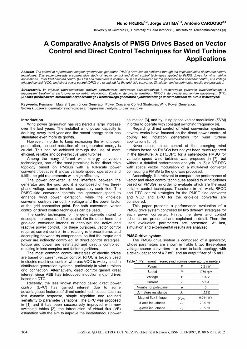
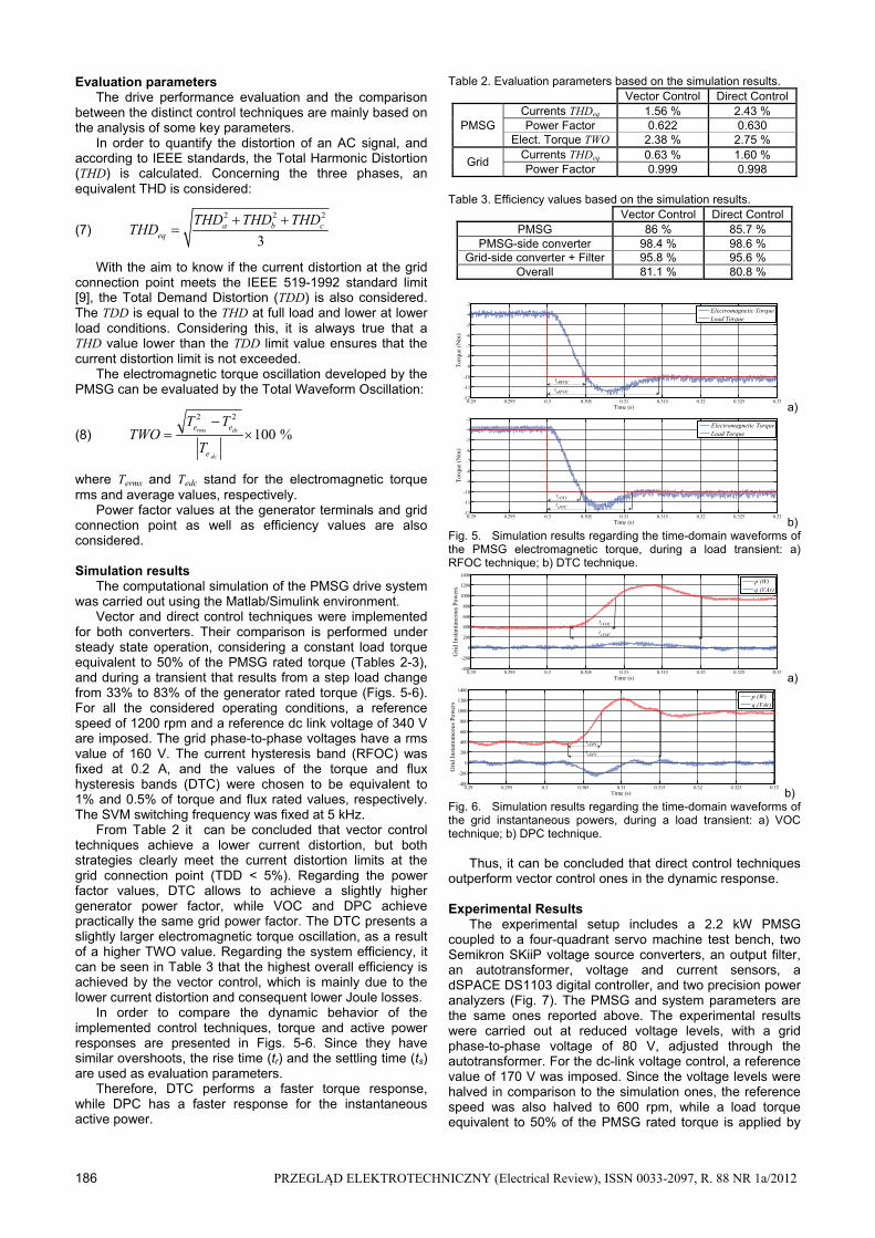
Vector and direct control techniques were implemented for both converters. Their comparison is performed under steady state operation, considering a constant load torque equivalent to 50% of the PMSG rated torque (Tables 2-3), and during a transient that results from a step load change from 33% to 83% of the generator rated torque (Figs. 5-6). For all the considered operating conditions, a reference speed of 1200 rpm and a reference dc link voltage of 340 V are imposed. The grid phase-to-phase voltages have a rms value of 160 V. The current hysteresis band (RFOC) was fixed at 0.2 A, and the values of the torque and flux hysteresis bands (DTC) were chosen to be equivalent to 1% and 0.5% of torque and flux rated values, respectively. The SVM switching frequency was fixed at 5 kHz.
From Table 2 it can be concluded that vector control techniques achieve a lower current distortion, but both strategies clearly meet the current distortion limits at the grid connection point (TDD < 5%). Regarding the power factor values, DTC allows to achieve a slightly higher generator power factor, while VOC and DPC achieve practically the same grid power factor. The DTC presents a slightly larger electromagnetic torque oscillation, as a result of a higher TWO value. Regarding the system efficiency, it can be seen in Table 3 that the highest overall efficiency is achieved by the vector control, which is mainly due to the lower current distortion and consequent lower Joule losses.
In order to compare the dynamic behavior of the implemented control techniques, torque and active power responses are presented in Figs. 5-6. Since they have similar overshoots, the rise time (tr) and the settling time (ts) are used as evaluation parameters.
Therefore, DTC performs a faster torque response, while DPC has a faster response for the instantaneous active power.
Table 2. Evaluation parameters based on the simulation results. Vector Control Direct Control
PMSG Currents THDeq 1.56 % 2.43 % Power Factor 0.622 0.630
Elect. Torque TWO 2.38 % 2.75 %
Grid Currents THDeq 0.63 % 1.60 % Power Factor 0.999 0.998
Table 3. Efficiency values based on the simulation results.
Vector Control Direct Control PMSG 86 % 85.7 %
PMSG-side converter 98.4 % 98.6 % Grid-side converter + Filter 95.8 % 95.6 %
Overall 81.1 % 80.8 %
0.29 0.295 0.3 0.305 0.31 0.315 0.32 0.325 0.33-12
-11
-10
-9
-8
-7
-6
-5
-4
-3
Time (s)
Tor
que
(Nm
)
Electromagnetic TorqueLoad Torque
trRFOC
tsRFOC
a)
0.29 0.295 0.3 0.305 0.31 0.315 0.32 0.325 0.33-12
-11
-10
-9
-8
-7
-6
-5
-4
-3
Time (s)
Tor
que
(Nm
)
Electromagnetic TorqueLoad Torque
trDTC
tsDTC
b) Fig. 5. Simulation results regarding the time-domain waveforms of the PMSG electromagnetic torque, during a load transient: a) RFOC technique; b) DTC technique.
0.29 0.295 0.3 0.305 0.31 0.315 0.32 0.325 0.33-400
-200
0
200
400
600
800
1000
1200
1400
Time (s)
Gri
d In
stan
tane
ous
Pow
ers
p (W)q (VAr)
trVOC
tsVOC
a)
0.29 0.295 0.3 0.305 0.31 0.315 0.32 0.325 0.33-400
-200
0
200
400
600
800
1000
1200
1400
Time (s)
Gri
d In
stan
tane
ous
Pow
ers
p (W)q (VAr)
trDPC
tsDPC
b) Fig. 6. Simulation results regarding the time-domain waveforms of the grid instantaneous powers, during a load transient: a) VOC technique; b) DPC technique. Thus, it can be concluded that direct control techniques outperform vector control ones in the dynamic response. Experimental Results
The experimental setup includes a 2.2 kW PMSG coupled to a four-quadrant servo machine test bench, two Semikron SKiiP voltage source converters, an output filter, an autotransformer, voltage and current sensors, a dSPACE DS1103 digital controller, and two precision power analyzers (Fig. 7). The PMSG and system parameters are the same ones reported above. The experimental results were carried out at reduced voltage levels, with a grid phase-to-phase voltage of 80 V, adjusted through the autotransformer. For the dc-link voltage control, a reference value of 170 V was imposed. Since the voltage levels were halved in comparison to the simulation ones, the reference speed was also halved to 600 rpm, while a load torque equivalent to 50% of the PMSG rated torque is applied by

PRZEGLĄD ELEKTROTECHNICZNY (Electrical Review), ISSN 0033-2097, R. 88 NR 1a/2012 187
the servo machine. The control strategies were implemented using a sample time of 30 μs.
The experimental results were obtained by two Yokogawa WT3000 precision power analyzers, which perform the harmonic measurement up to the 100th order.
All the obtained experimental results are similar to the simulations ones, despite of the differences regarding the considered lower voltage and speed values. Then, it can be also verified that with vector control it is possible to achieve a higher efficiency than with direct control (Table 4). Additionally, the drive operation with vector control presents lower THD values and a higher grid power factor (Table 5). However, direct control of the PMSG achieves a higher generator power factor. Still regarding the distortion values, it is clear from Fig. 8 that the PMSG currents have a higher harmonic content for DTC.
Fig. 9 shows phase A current and voltage at the grid connection point, where it can be seen that for both control strategies they are in phase, meaning that a power factor close to one is achieved. Since the grid connection point is considered at the autotransformer low voltage side, due to the transformer’s impedance, the voltage waveform has a noticeable distortion, which will be practically unnoticed at the mains side. Despite this, at the considered analysis point, the IEEE Std 519 distortion limits (ITDDmax=5%, VTHDmax=5%) are clearly met by both control techniques (Table 5).
Fig. 7. Detail of the PMSG coupled to the servo machine (left) and general view of the power and control stages (right).
a) RFOC
b) DTC
Fig. 8. Experimental results regarding the time-domain waveforms of the PMSG phase currents (1.5 A/div) and the spectrogram of the PMSG phase a current: a) vector control; b) direct control.
a) VOC
b) DPC
Fig. 9. Experimental results regarding the time-domain waveforms of the grid phase A current (3.75 A/div) and grid phase A voltage (25 V/div): a) vector control; b) direct control.
Table 4. Efficiency values based on the experimental results. Vector Control Direct Control
PMSG 81.8 % 81 % PMSG-side converter 95.8 % 96.9 %
Grid-side converter + Filter 91.9 % 91.7 % Overall 72 % 71.9 %
Table 5. Evaluation parameters based on the experimental results.
Vector Control Direct Control
PMSG Currents THDeq 0.8 % 3.5 % Power Factor 0.635 0.642
Grid Voltages THDeq 3.49 % 3.64 % Currents THDeq 0.9 % 2.9 % Power Factor 0.998 0.992
Conclusions
The performed comparative study allows to conclude that all the implemented control strategies are suitable to PMSG drives for wind turbines applications. However, with vector control techniques applied to the drive, it shows a better general performance since lower current distortion, higher grid power factor and higher overall efficiency are obtained. On the other hand, direct control has a better dynamic response and it is less computational demanding. Vector and direct control combination might be an ideal choice, depending on the desired performance tradeoff. The authors gratefully acknowledge the financial support of the Portuguese Foundation for Science and Technology (FCT) under Project No. SFRH/BD/40286/2007 , Project No. SFRH/BD/70868/2010, and Project No. PTDC/EEA-EEL/114846/2009.
REFERENCES [1] T. Noguchi, H. Tomiki, S. Kondo, and I. Takahashi, “Direct
power control of PWM converter without power-source voltage sensors”, IEEE Trans. on Ind. Appl, vol. 34, no. 3, pp. 473-479, May/June 1998
[2] J. A. Martínez, J. E. G. Carrasco and S. Arnaltes, “Table-based direct power control: a critical review for microgrid applications”, IEEE Trans. on Power Electron., vol. 25, no. 12, pp. 2949-2961, Dec. 2010
[3] M. Malinowski, M. P. Kazmierkowski, S. Hansen, F. Blaabjerg and G. D. Marques, “Virtual-flux-based direct power control of three-phase PWM rectifiers”, IEEE Trans. on Ind. Appl., vol. 37, no. 4, pp. 1019-1027, July/Aug. 2001
[4] M. Malinowski and M. P. Kazmierkowski, “DSP implementation of direct power control with constant switching frequency for three-phase PWM rectifiers”, 28th Annual Conf. of the Ind. Electron. Society, vol. 1, pp. 198-203, March 2002
[5] D. Zhiand and L. Xu, “Direct power control of DFIG with constant switching frequency and improved transient performance”, IEEE Trans. on Energy Convers., vol. 22, no. 1, pp. 110-118, March 2007
[6] D. Chwa and K. B. Lee, “Variable structure control of the active and reactive powers for a DFIG in wind turbines”, IEEE Trans. on Ind. Appl., vol. 46, no. 6, pp. 2545-2555, Nov./Dec. 2010
[7] I. Schmidt and K. Veszprémi, “Application of direct controls to variable–speed wind generators”, Int. Conf. on Ind. Electron. and Control Appl., 6 pp., June 2005
[8] M. Malinowski, S. Stynski, W. Kolomyjski and M. P. Kazmierkowski, “Control of three-level PWM converter applied to variable-speed-type turbines”, IEEE Trans. on Ind. Electron., vol. 56, no. 1, pp. 69-77, Jan. 2009
[9] “IEEE Recommended practices and requirements for harmonic control in electrical power systems”, IEEE Std 519-1992, 1993
Authors: The authors are with the Instituto de Telecomunicacões, P-3030-290 Coimbra, Portugal (e-mail: [email protected]; [email protected]; [email protected]).