Embed Size (px)
Citation preview
Neal P. Dillon1
Department of Mechanical Engineering,
Vanderbilt University,
2301 Vanderbilt Place,
PMB 351592,
Nashville, TN 37235
e-mail: [email protected]
Ramya BalachandranDepartment of Otolaryngology,
Vanderbilt University Medical Center,
1215 21st Avenue South,
MCE 10450,
Nashville, TN 37232
e-mail: [email protected]
J. Michael FitzpatrickDepartment of Electrical Engineering and
Computer Science,
Vanderbilt University,
2301 Vanderbilt Place,
PMB 351679,
Nashville, TN 37235
e-mail: [email protected]
Michael A. SieboldDepartment of Electrical Engineering and
Computer Science,
Vanderbilt University,
2301 Vanderbilt Place,
PMB 351679,
Nashville, TN 37235
e-mail: [email protected]
Robert F. LabadieDepartment of Otolaryngology,
Vanderbilt University Medical Center,
1215 21st Avenue South,
MCE 10450,
Nashville, TN 37232
e-mail: [email protected]
George B. WannaDepartment of Otolaryngology,
Vanderbilt University Medical Center,
1215 21st Avenue South,
MCE 10450,
Nashville, TN 37232
e-mail: [email protected]
Thomas J. WithrowDepartment of Mechanical Engineering,
Vanderbilt University,
2301 Vanderbilt Place,
PMB 351592,
Nashville, TN 37235
e-mail: [email protected]
Robert J. Webster, IIIDepartment of Mechanical Engineering,
Vanderbilt University,
2301 Vanderbilt Place,
PMB 351592,
Nashville, TN 37235
e-mail: [email protected]
A Compact, Bone-AttachedRobot for MastoidectomyOtologic surgery often involves a mastoidectomy, which is the removal of a portion of themastoid region of the temporal bone, to safely access the middle and inner ear. The surgeryis challenging because many critical structures are embedded within the bone, makingthem difficult to see and requiring a high level of accuracy with the surgical dissectioninstrument, a high-speed drill. We propose to automate the mastoidectomy portion of thesurgery using a compact, bone-attached robot. The system described in this paper is a mill-ing robot with four degrees-of-freedom (DOF) that is fixed to the patient during surgeryusing a rigid positioning frame screwed into the surface of the bone. The target volume tobe removed is manually identified by the surgeon pre-operatively in a computed tomogra-phy (CT) scan and converted to a milling path for the robot. The surgeon attaches the robotto the patient in the operating room and monitors the procedure. Several design considera-tions are discussed in the paper as well as the proposed surgical workflow. The mean tar-geting error of the system in free space was measured to be 0.5 mm or less at vitalstructures. Four mastoidectomies were then performed in cadaveric temporal bones, andthe error at the edges of the target volume was measured by registering a postoperativecomputed tomography (CT) to the pre-operative CT. The mean error along the border ofthe milled cavity was 0.38 mm, and all critical anatomical structures were preserved.[DOI: 10.1115/1.4030083]
1Corresponding author.Manuscript received November 21, 2014; final manuscript received March 10,
2015; published online July 16, 2015. Assoc. Editor: Lewis Franklin Bost.
Journal of Medical Devices SEPTEMBER 2015, Vol. 9 / 031003-1Copyright VC 2015 by ASME
Downloaded From: http://medicaldevices.asmedigitalcollection.asme.org/ on 09/09/2015 Terms of Use: http://www.asme.org/about-asme/terms-of-use
1 Introduction
Mastoidectomy is a common procedure in otologic surgery thatconsists of removal of all or part of the mastoid portion of thetemporal bone with a high-speed surgical drill. The procedure canbe performed on its own to treat diseases and infections such asmastoiditis and cholesteatoma, or it can be performed as a compo-nent of other surgeries such as a facial recess approach for coch-lear implantation (CI) or translabyrinthine approach for acousticneuroma removal. During a facial recess approach for CI, a mas-toidectomy is followed by opening the region just anterior tothe facial nerve to allow access to the cochlea. During a transla-byrinthine approach for acoustic neuroma (a.k.a. vestibularschwannoma) removal, a mastoidectomy is followed by a labyrin-thectomy in which deeper dissection into the temporal boneremoves a portion of the inner ear to allow access to the skullbase, specifically the internal auditory canal (IAC) where thetumor is located.
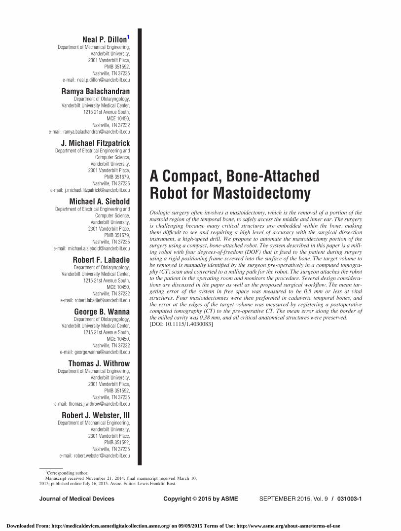
Many critical anatomical structures are embedded within thebone of the mastoid (Fig. 1) including the facial nerve, which con-trols motion of the face, large blood vessels such as the carotidartery and intracranial continuation of the jugular vein, and thetegmen, which is the boundary between the mastoid and the brain.Because injury to these vital structures can lead to morbidity, sur-geons manually identify these structures using visual and tactilefeedback and then remove bone as needed around them. Thisidentification is challenging and makes ear surgery, and mastoi-dectomy, in particular, well-suited for image-guided robotic assis-tance. We hypothesize that a robotic system guided by pre-operative images could be used to remove bone, while preservingappropriate safety margins around the critical structures withinthe bone. By automating the bulk removal of bone using image-guidance, such a system would allow surgeons to focus on themore delicate portions of the surgery (e.g., inserting the electrodearray for CI, or removing the acoustic neuroma from the brain-stem) and could potentially save time in the operating room,thereby reducing the cost of caring for each patient.
Robotic bone milling has been a topic of research and commer-cial development for over 20 years [1–3] with most work focusingon orthopedic procedures such as joint arthroplasty and resurfac-ing. Several of these systems have been successfully commercial-ized and are currently used clinically (e.g., RIO System byMAKO Surgical Corp., Ft. Lauderdale, FL; ROBODOC SurgicalSystem by Curexo Technology Corp., Fremont, CA; and CAS-PAR by URS Ortho GMBH & Co. KG, Rastatt, Germany). Bonemilling is a task well-suited for robotic assistance and, because ofthe similarities to computer-numeric-control (CNC) machining,was one of the first surgical procedures to employ a robot. Therigidity of bone allows for the entire procedure to be planned pre-operatively since deformity of bone geometry during surgery isminimal. Robotic milling of the temporal bone in ear surgery is alogical extension of previous robotic orthopedic procedures. How-ever, ear surgery presents additional challenges not encounteredin orthopedic procedures primarily due to the presence of rela-tively small and complex anatomy in and around the targetregions. As such, the task requires submillimetric accuracy [4].
Several research groups have investigated robotic mastoidec-tomy [5–8] and have successfully demonstrated such in the labo-ratory. Like their orthopedic predecessors, these systems uselarge, free-standing robots. These robots take up significant spacein the operating room and typically provide a workspace that islarger than the necessary workspace for otologic surgery. Addi-tionally, free-standing robots require an alignment between therobot’s coordinate system and the patient’s anatomy throughoutthe procedure. The alignment is typically performed using an opti-cal tracking system that continuously monitors the robot and thepatient. These systems provide excellent image guidance formany procedures; however, the error associated with a trackingsystem, compounded with errors in other components of the sys-tem, makes it difficult to meet the submillimetric accuracyrequirement of otologic surgery. To address this issue, theresearch group led by Weber has developed a system that employsa very accurate external tracking system with a small working vol-ume positioned close to the target anatomy [9,10]. This systemguides a robot that is mounted to the bed as near as possible to thepatient and is used to drill a narrow path directly to the cochleafor a minimally invasive CI. Using this system, the group reportsaccuracies sufficient for otologic surgery.
The approach outlined in this paper uses a compact, bone-attached robot designed specifically for temporal bone milling.The direct fixation of the robot to the patient’s skull eliminates theneed for monitoring relative motion between the robot and thepatient and permits highly accurate registration of the robot tothe patient’s anatomy. The compact robot design is suitable forthe small surgical area of otologic procedures. Prior work usingbone-attached robots has shown them to be capable of millingbone in orthopedic surgery [11–13] as well as providing effectivealternatives to stereotactic frames for minimally invasive otologicsurgery [14,15]. In this paper, we use a bone-attached robot to per-form accurate mastoidectomies on cadaveric specimens. A pre-liminary description of the robot and some bench top tests, notincluding cadavers, appeared in Ref. [16].
2 Surgical Workflow
With the proposed robotic system, the workflow of the surgeryinvolves pre-operative planning followed by a series of steps per-formed in the operating room (Fig. 2). Vital structures are seg-mented, i.e., identified, automatically in the pre-operative CT,including the facial nerve, chorda tympani, external auditorycanal, semicircular canals, and ossicles using previously describedmethods [17,18]. Using the locations of these structures as guid-ance, the volume of bone to be removed in surgery is then man-ually segmented by the surgeon in the CT scan. In the operatingroom, a prepositioning frame (PPF), containing three titaniumspheres, is attached to the patient using small screws via stab inci-sions. The spheres serve not only as fiducial markers for
Fig. 1 Mastoid region of the temporal bone and photographfrom surgical case showing the region after the target bone hasbeen removed with several key anatomical structures identified
031003-2 / Vol. 9, SEPTEMBER 2015 Transactions of the ASME
Downloaded From: http://medicaldevices.asmedigitalcollection.asme.org/ on 09/09/2015 Terms of Use: http://www.asme.org/about-asme/terms-of-use
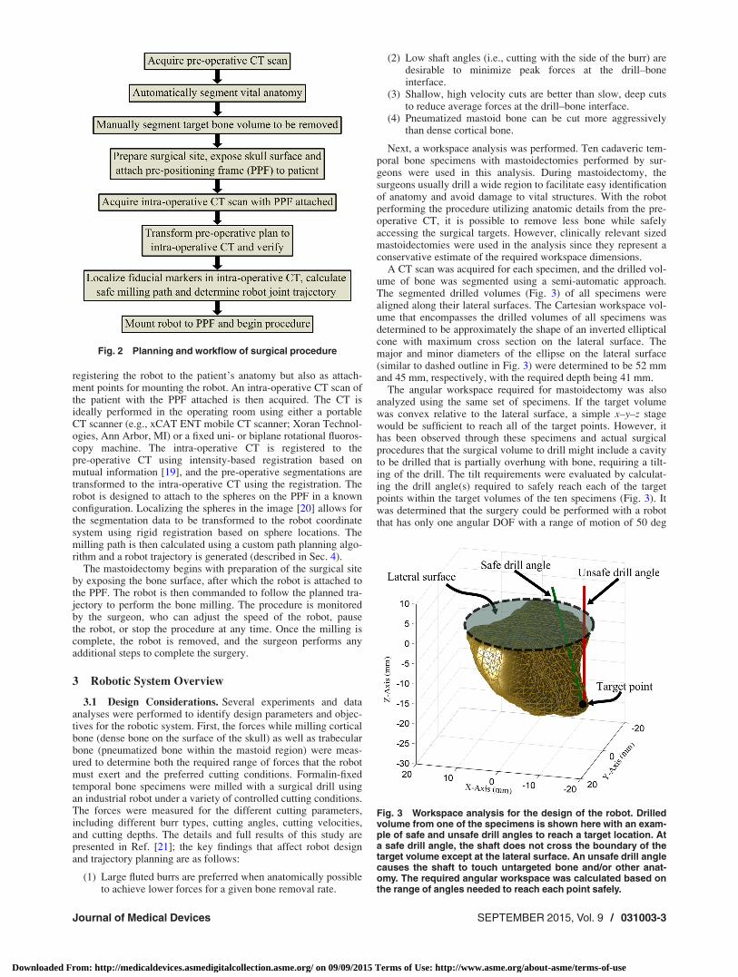
registering the robot to the patient’s anatomy but also as attach-ment points for mounting the robot. An intra-operative CT scan ofthe patient with the PPF attached is then acquired. The CT isideally performed in the operating room using either a portableCT scanner (e.g., xCAT ENT mobile CT scanner; Xoran Technol-ogies, Ann Arbor, MI) or a fixed uni- or biplane rotational fluoros-copy machine. The intra-operative CT is registered to thepre-operative CT using intensity-based registration based onmutual information [19], and the pre-operative segmentations aretransformed to the intra-operative CT using the registration. Therobot is designed to attach to the spheres on the PPF in a knownconfiguration. Localizing the spheres in the image [20] allows forthe segmentation data to be transformed to the robot coordinatesystem using rigid registration based on sphere locations. Themilling path is then calculated using a custom path planning algo-rithm and a robot trajectory is generated (described in Sec. 4).
The mastoidectomy begins with preparation of the surgical siteby exposing the bone surface, after which the robot is attached tothe PPF. The robot is then commanded to follow the planned tra-jectory to perform the bone milling. The procedure is monitoredby the surgeon, who can adjust the speed of the robot, pausethe robot, or stop the procedure at any time. Once the milling iscomplete, the robot is removed, and the surgeon performs anyadditional steps to complete the surgery.
3 Robotic System Overview
3.1 Design Considerations. Several experiments and dataanalyses were performed to identify design parameters and objec-tives for the robotic system. First, the forces while milling corticalbone (dense bone on the surface of the skull) as well as trabecularbone (pneumatized bone within the mastoid region) were meas-ured to determine both the required range of forces that the robotmust exert and the preferred cutting conditions. Formalin-fixedtemporal bone specimens were milled with a surgical drill usingan industrial robot under a variety of controlled cutting conditions.The forces were measured for the different cutting parameters,including different burr types, cutting angles, cutting velocities,and cutting depths. The details and full results of this study arepresented in Ref. [21]; the key findings that affect robot designand trajectory planning are as follows:
(1) Large fluted burrs are preferred when anatomically possibleto achieve lower forces for a given bone removal rate.
(2) Low shaft angles (i.e., cutting with the side of the burr) aredesirable to minimize peak forces at the drill–boneinterface.
(3) Shallow, high velocity cuts are better than slow, deep cutsto reduce average forces at the drill–bone interface.
(4) Pneumatized mastoid bone can be cut more aggressivelythan dense cortical bone.
Next, a workspace analysis was performed. Ten cadaveric tem-poral bone specimens with mastoidectomies performed by sur-geons were used in this analysis. During mastoidectomy, thesurgeons usually drill a wide region to facilitate easy identificationof anatomy and avoid damage to vital structures. With the robotperforming the procedure utilizing anatomic details from the pre-operative CT, it is possible to remove less bone while safelyaccessing the surgical targets. However, clinically relevant sizedmastoidectomies were used in the analysis since they represent aconservative estimate of the required workspace dimensions.
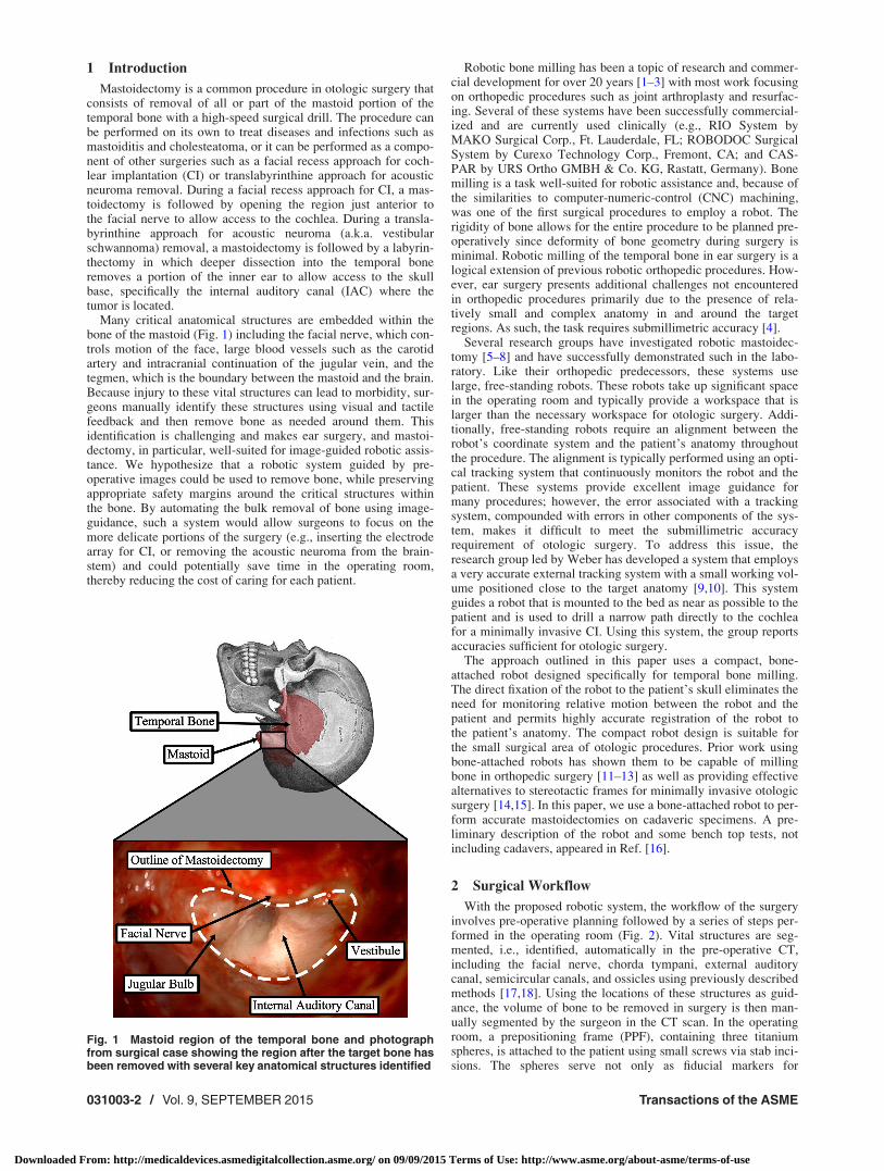
A CT scan was acquired for each specimen, and the drilled vol-ume of bone was segmented using a semi-automatic approach.The segmented drilled volumes (Fig. 3) of all specimens werealigned along their lateral surfaces. The Cartesian workspace vol-ume that encompasses the drilled volumes of all specimens wasdetermined to be approximately the shape of an inverted ellipticalcone with maximum cross section on the lateral surface. Themajor and minor diameters of the ellipse on the lateral surface(similar to dashed outline in Fig. 3) were determined to be 52 mmand 45 mm, respectively, with the required depth being 41 mm.
The angular workspace required for mastoidectomy was alsoanalyzed using the same set of specimens. If the target volumewas convex relative to the lateral surface, a simple x–y–z stagewould be sufficient to reach all of the target points. However, ithas been observed through these specimens and actual surgicalprocedures that the surgical volume to drill might include a cavityto be drilled that is partially overhung with bone, requiring a tilt-ing of the drill. The tilt requirements were evaluated by calculat-ing the drill angle(s) required to safely reach each of the targetpoints within the target volumes of the ten specimens (Fig. 3). Itwas determined that the surgery could be performed with a robotthat has only one angular DOF with a range of motion of 50 deg
Fig. 3 Workspace analysis for the design of the robot. Drilledvolume from one of the specimens is shown here with an exam-ple of safe and unsafe drill angles to reach a target location. Ata safe drill angle, the shaft does not cross the boundary of thetarget volume except at the lateral surface. An unsafe drill anglecauses the shaft to touch untargeted bone and/or other anat-omy. The required angular workspace was calculated based onthe range of angles needed to reach each point safely.
Fig. 2 Planning and workflow of surgical procedure
Journal of Medical Devices SEPTEMBER 2015, Vol. 9 / 031003-3
Downloaded From: http://medicaldevices.asmedigitalcollection.asme.org/ on 09/09/2015 Terms of Use: http://www.asme.org/about-asme/terms-of-use
(4DOF total, including x–y–z motion). The robot must be alignedsuch that the single angular DOF aligns with the overhung area onthe patient. The reduced complexity of the robot and limited sour-ces of error associated with fewer joints (compared to a 6DOFrobot) must be weighed against the additional requirement ofaligning the robot with the patient anatomy. However, since thedirection of the overhung region is consistent among patients, thisalignment can be easily accomplished with a simple mechanismto show the surgeon the desired orientation to attach the robot.
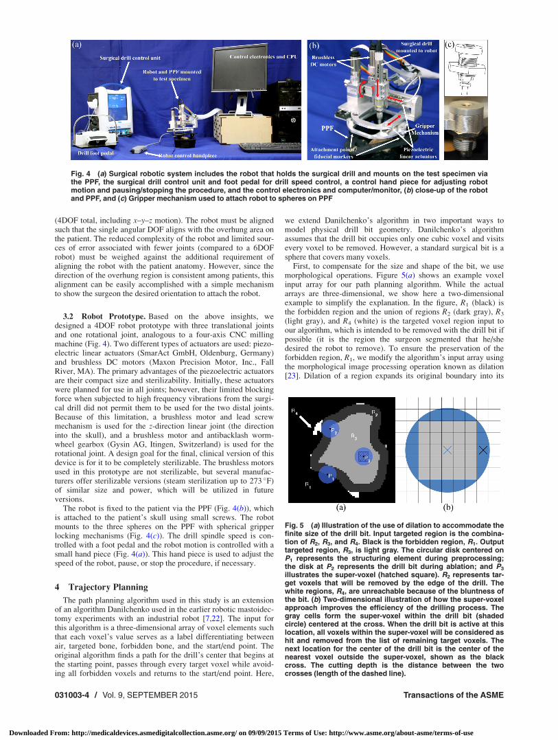
3.2 Robot Prototype. Based on the above insights, wedesigned a 4DOF robot prototype with three translational jointsand one rotational joint, analogous to a four-axis CNC millingmachine (Fig. 4). Two different types of actuators are used: piezo-electric linear actuators (SmarAct GmbH, Oldenburg, Germany)and brushless DC motors (Maxon Precision Motor, Inc., FallRiver, MA). The primary advantages of the piezoelectric actuatorsare their compact size and sterilizability. Initially, these actuatorswere planned for use in all joints; however, their limited blockingforce when subjected to high frequency vibrations from the surgi-cal drill did not permit them to be used for the two distal joints.Because of this limitation, a brushless motor and lead screwmechanism is used for the z-direction linear joint (the directioninto the skull), and a brushless motor and antibacklash worm-wheel gearbox (Gysin AG, Itingen, Switzerland) is used for therotational joint. A design goal for the final, clinical version of thisdevice is for it to be completely sterilizable. The brushless motorsused in this prototype are not sterilizable, but several manufac-turers offer sterilizable versions (steam sterilization up to 273 �F)of similar size and power, which will be utilized in futureversions.
The robot is fixed to the patient via the PPF (Fig. 4(b)), whichis attached to the patient’s skull using small screws. The robotmounts to the three spheres on the PPF with spherical gripperlocking mechanisms (Fig. 4(c)). The drill spindle speed is con-trolled with a foot pedal and the robot motion is controlled with asmall hand piece (Fig. 4(a)). This hand piece is used to adjust thespeed of the robot, pause, or stop the procedure, if necessary.
4 Trajectory Planning
The path planning algorithm used in this study is an extensionof an algorithm Danilchenko used in the earlier robotic mastoidec-tomy experiments with an industrial robot [7,22]. The input forthis algorithm is a three-dimensional array of voxel elements suchthat each voxel’s value serves as a label differentiating betweenair, targeted bone, forbidden bone, and the start/end point. Theoriginal algorithm finds a path for the drill’s center that begins atthe starting point, passes through every target voxel while avoid-ing all forbidden voxels and returns to the start/end point. Here,
we extend Danilchenko’s algorithm in two important ways tomodel physical drill bit geometry. Danilchenko’s algorithmassumes that the drill bit occupies only one cubic voxel and visitsevery voxel to be removed. However, a standard surgical bit is asphere that covers many voxels.
First, to compensate for the size and shape of the bit, we usemorphological operations. Figure 5(a) shows an example voxelinput array for our path planning algorithm. While the actualarrays are three-dimensional, we show here a two-dimensionalexample to simplify the explanation. In the figure, R1 (black) isthe forbidden region and the union of regions R2 (dark gray), R3
(light gray), and R4 (white) is the targeted voxel region input toour algorithm, which is intended to be removed with the drill bit ifpossible (it is the region the surgeon segmented that he/shedesired the robot to remove). To ensure the preservation of theforbidden region, R1, we modify the algorithm’s input array usingthe morphological image processing operation known as dilation[23]. Dilation of a region expands its original boundary into its
Fig. 4 (a) Surgical robotic system includes the robot that holds the surgical drill and mounts on the test specimen viathe PPF, the surgical drill control unit and foot pedal for drill speed control, a control hand piece for adjusting robotmotion and pausing/stopping the procedure, and the control electronics and computer/monitor, (b) close-up of the robotand PPF, and (c) Gripper mechanism used to attach robot to spheres on PPF
Fig. 5 (a) Illustration of the use of dilation to accommodate thefinite size of the drill bit. Input targeted region is the combina-tion of R2, R3, and R4. Black is the forbidden region, R1. Outputtargeted region, R3, is light gray. The circular disk centered onP1 represents the structuring element during preprocessing;the disk at P2 represents the drill bit during ablation; and P3
illustrates the super-voxel (hatched square). R2 represents tar-get voxels that will be removed by the edge of the drill. Thewhite regions, R4, are unreachable because of the bluntness ofthe bit. (b) Two-dimensional illustration of how the super-voxelapproach improves the efficiency of the drilling process. Thegray cells form the super-voxel within the drill bit (shadedcircle) centered at the cross. When the drill bit is active at thislocation, all voxels within the super-voxel will be considered ashit and removed from the list of remaining target voxels. Thenext location for the center of the drill bit is the center of thenearest voxel outside the super-voxel, shown as the blackcross. The cutting depth is the distance between the twocrosses (length of the dashed line).
031003-4 / Vol. 9, SEPTEMBER 2015 Transactions of the ASME
Downloaded From: http://medicaldevices.asmedigitalcollection.asme.org/ on 09/09/2015 Terms of Use: http://www.asme.org/about-asme/terms-of-use
surroundings in a manner determined by the size and shape of aspecified “structuring element.” The structuring element used todilate R1 in our approach is the circle shown centered on P1. Theidentical disk surrounding P2 depicts the drill bit at a specificpoint on the output path. The dimensions of the structuring ele-ment are chosen to match those of the drill bit. The dilation of R1
is accomplished by placing the center of the structuring elementon every voxel in R1 and moving all voxels within the structuringelement into R2. The new dilated forbidden region is the combina-tion of R1, R2, and R4.
The resultant modified targeted region, R3, serves as input tothe path planning algorithm, which determines a path for the cen-ter of the drill bit through a sequence of R3 voxels such that all ofthe voxels in R2 and R3 are removed by some portion of the spher-ical drill tip. The drill’s position, P2, in the target region has beenchosen to illustrate a limitation imposed by the bit’s physicalshape and size. Voxels in R4 are located such that they cannot beremoved by the drill bit without also removing at least one forbid-den voxel. This problem is a consequence of the dimensions ofthe bit and also exists when the drilling is performed by hand.These unreachable nooks are filled in during the preprocessingdilation. Additionally, a check for connectedness ensures that weeliminate any isolated, unreachable pockets of R3. All forbiddenvoxels are protected at the expense of allowing some targetedvoxels to remain undrilled ensuring that the algorithm adheres tothe rule “first do no harm.” The drill angle associated with eachtarget voxel is determined after the path is generated based on thelocation of the drill bit within the volume, the locations of nearbyundrilled voxels, and potential collisions between the shaft andundrilled/untargeted bone.
Our second modification of Danilchenko’s original algorithmstems from its requirement in that algorithm that the drill bit’scenter visit each target voxel, thereby leaving the relationshipbetween the bit’s physical size and the dimensions of the targetvoxels unexploited. We account for the size of the drill bit as itpasses through the target voxel region, R3, by creating a “super-voxel” centered on the drill bit and consisting of a group of targetvoxels whose size is determined by the desired cutting depth. Asthe path of the drill’s center is planned through R3, all of the targetvoxels within the super-voxel are considered to be removed(hatched square within P3 shown in Fig. 5(a)). The identificationof these voxels increases efficiency and results in considerabletime savings. An exception to this rule occurs at those voxels inR3 that border R2. These voxels must be touched with the centerof the drill bit to ensure that the entire original target region isremoved. The super-voxel approach allows for the adjustment ofthe cutting depth of the drill bit by changing the number of targetvoxels contained within the super-voxel. For example, without thesuper-voxel approach, given a voxel size of 0.4� 0.4� 0.4 mm,the commanded cutting depth of the drill would be 0.4 mm. Usingthe super-voxel approach, the cutting depth would be equal to thedistance between the center of the super-voxel to the center of thenearest voxel outside the super-voxel (Fig. 5(b)). For example,given an image with voxel size of 0.4� 0.4� 0.4 mm and a5� 5� 5 super-voxel, the cutting depth will be 1.2 mm.
5 Experimental Results
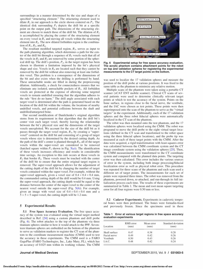
5.1 Free Space Accuracy Evaluation. The free space accu-racy of the system was evaluated using the virtual target methoddescribed in Ref. [24] using a custom phantom and drill probe(Fig. 6). The robot attaches to the top of the phantom via threetitanium spheres similar to how it would attach to the PPF. Seven-teen titanium spheres are embedded on the bottom of the phantomto serve as validation markers to register the CT scan of the phan-tom to the coordinate measurement machine (CMM) used to testthe accuracy in these experiments. The CMM used is a FAROGagePlus (FARO Technologies, Inc., Lake Mary, FL), which hasan accuracy of 0.025 mm within its working volume. The CMM
was used to localize the 17 validation spheres and measure theposition of the drill probe at various positions. It was fixed to thesame table as the phantom to minimize any relative motion.
Multiple scans of the phantom were taken using a portable CTscanner (xCAT ENT mobile scanner). Clinical CT scans of sev-eral patients were used to determine clinically relevant targetpoints at which to test the accuracy of the system. Points on thebone surface, in regions close to the facial nerve, the vestibule,and the IAC were chosen as test points. These points were thensuperimposed onto the scan of the phantom to serve as the “virtualtargets” in the experiment. Additionally, each of the 17 validationspheres and the three robot fiducial spheres were automaticallylocalized in the CT scan of the phantom.
The robot was then mounted onto the test phantom, and the 17validation spheres were localized using the CMM. The robot wasprogramd to move the drill probe to the eight virtual target loca-tions (defined in the CT scan and transformed to the robot spaceusing the three fiducial sphere locations), and the probe tip wasmeasured at each of these target points with the CMM. After thedata were acquired, a rigid transformation with least-squares errorwas calculated between the CMM coordinate system and the CTimage coordinate system using the validation spheres [25]. Then,the CMM measurements were transformed to the CT coordinatesystem and compared with the planned data points. The targetingerror was then calculated. This error includes the various sourcesof error in the system, including both image processing/fiduciallocalization error as well as physical robot error. This procedurewas repeated for three scans of the phantom and each scan used adifferent set of target points. The measurements for each set ofpoints were repeated three times. The robot was removed from thephantom, powered down, re-attached, and run-through its full ini-tialization process each time. The results of these experiments aresummarized in Table 1. The mean and root mean square targetingerror for all four regions were 0.50 mm or less.
5.2 Cadaver Experiments. Experiments in cadaveric tempo-ral bones were then performed. The bones were formalin-fixedand previously frozen. Since the specimens used in these
Fig. 6 Experimental setup for free space accuracy evaluation.The acrylic phantom contains attachment points for the roboton top and validation spheres for registering the experimentalmeasurements to the CT target points on the bottom.
Table 1 Error at various target regions in free space accuracyevaluation experiments
LocationRMS error
(mm)Mean error
(mm)Standard deviation
(mm)
Skull surface 0.47 0.38 0.28Facial nerve 0.49 0.42 0.26Vestibule 0.50 0.43 0.26I.A.C. 0.48 0.42 0.24
Journal of Medical Devices SEPTEMBER 2015, Vol. 9 / 031003-5
Downloaded From: http://medicaldevices.asmedigitalcollection.asme.org/ on 09/09/2015 Terms of Use: http://www.asme.org/about-asme/terms-of-use
experiments are only partial temporal bones and the robot requiresa larger surface area for attaching the PPF, the bones were cast ina hard urethane compound to provide enough space for the attach-ment. These experiments followed the surgical workflow outlinedin Sec. 2 with one exception: the segmentations were performedin the scan acquired with the PPF attached (defined as intra-operative scan in Sec. 2) rather than the pre-operative scan beforeattaching the PPF. A 5 mm diameter spherical, fluted drill burrwas used in all trials. After the procedure was completed, a post-operative CT scan was acquired. The removed volume was seg-mented using a semi-automatic method, and the postoperativescan was registered to the pre-operative scan for comparison ofthe planned versus milled volume and to check for violation of thecritical anatomy. Additionally, the specimens were examined byan experienced surgeon postoperatively.
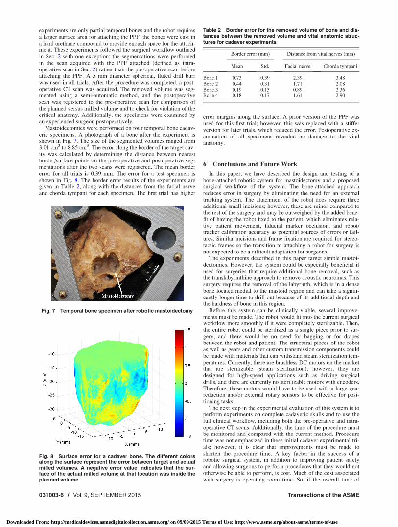
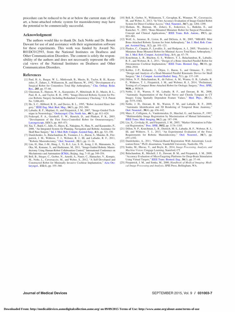
Mastoidectomies were performed on four temporal bone cadav-eric specimens. A photograph of a bone after the experiment isshown in Fig. 7. The size of the segmented volumes ranged from3.01 cm3 to 8.85 cm3. The error along the border of the target cav-ity was calculated by determining the distance between nearestborder/surface points on the pre-operative and postoperative seg-mentations after the two scans were registered. The mean bordererror for all trials is 0.39 mm. The error for a test specimen isshown in Fig. 8. The border error results of the experiments aregiven in Table 2, along with the distances from the facial nerveand chorda tympani for each specimen. The first trial has higher
error margins along the surface. A prior version of the PPF wasused for this first trial; however, this was replaced with a stifferversion for later trials, which reduced the error. Postoperative ex-amination of all specimens revealed no damage to the vitalanatomy.
6 Conclusions and Future Work
In this paper, we have described the design and testing of abone-attached robotic system for mastoidectomy and a proposedsurgical workflow of the system. The bone-attached approachreduces error in surgery by eliminating the need for an externaltracking system. The attachment of the robot does require threeadditional small incisions; however, these are minor compared tothe rest of the surgery and may be outweighed by the added bene-fit of having the robot fixed to the patient, which eliminates rela-tive patient movement, fiducial marker occlusion, and robot/tracker calibration accuracy as potential sources of errors or fail-ures. Similar incisions and frame fixation are required for stereo-tactic frames so the transition to attaching a robot for surgery isnot expected to be a difficult adaptation for surgeons.
The experiments described in this paper target simple mastoi-dectomies. However, the system could be especially beneficial ifused for surgeries that require additional bone removal, such asthe translabyrinthine approach to remove acoustic neuromas. Thissurgery requires the removal of the labyrinth, which is in a densebone located medial to the mastoid region and can take a signifi-cantly longer time to drill out because of its additional depth andthe hardness of bone in this region.
Before this system can be clinically viable, several improve-ments must be made. The robot would fit into the current surgicalworkflow more smoothly if it were completely sterilizable. Then,the entire robot could be sterilized as a single piece prior to sur-gery, and there would be no need for bagging or for drapesbetween the robot and patient. The structural pieces of the robotas well as gears and other custom transmission components couldbe made with materials that can withstand steam sterilization tem-peratures. Currently, there are brushless DC motors on the marketthat are sterilizable (steam sterilization); however, they aredesigned for high-speed applications such as driving surgicaldrills, and there are currently no sterilizable motors with encoders.Therefore, these motors would have to be used with a large gearreduction and/or external rotary sensors to be effective for posi-tioning tasks.
The next step in the experimental evaluation of this system is toperform experiments on complete cadaveric skulls and to use thefull clinical workflow, including both the pre-operative and intra-operative CT scans. Additionally, the time of the procedure mustbe monitored and compared with the current method. Proceduretime was not emphasized in these initial cadaver experimental tri-als; however, it is clear that improvements must be made toshorten the procedure time. A key factor in the success of arobotic surgical system, in addition to improving patient safetyand allowing surgeons to perform procedures that they would nototherwise be able to perform, is cost. Much of the cost associatedwith surgery is operating room time. So, if the overall time of
Fig. 7 Temporal bone specimen after robotic mastoidectomy
Fig. 8 Surface error for a cadaver bone. The different colorsalong the surface represent the error between target and actualmilled volumes. A negative error value indicates that the sur-face of the actual milled volume at that location was inside theplanned volume.
Table 2 Border error for the removed volume of bone and dis-tances between the removed volume and vital anatomic struc-tures for cadaver experiments
Border error (mm) Distance from vital nerves (mm)
Mean Std. Facial nerve Chorda tympani
Bone 1 0.73 0.39 2.39 3.48Bone 2 0.44 0.31 1.71 2.08Bone 3 0.19 0.13 0.89 2.36Bone 4 0.18 0.17 1.61 2.90
031003-6 / Vol. 9, SEPTEMBER 2015 Transactions of the ASME
Downloaded From: http://medicaldevices.asmedigitalcollection.asme.org/ on 09/09/2015 Terms of Use: http://www.asme.org/about-asme/terms-of-use
procedure can be reduced to be at or below the current state of theart, a bone-attached robotic system for mastoidectomy may havethe potential to be commercially successful.
Acknowledgment
The authors would like to thank Dr. Jack Noble and Dr. BenoitDawant for use of and assistance with their segmentation softwarefor these experiments. This work was funded by Award No.R01DC012593, from the National Institutes on Deafness andOther Communication Disorders. The content is solely the respon-sibility of the authors and does not necessarily represent the offi-cial views of the National Institutes on Deafness and OtherCommunication Disorders.
References[1] Paul, H. A., Bargar, W. L., Mittlestadt, B., Musits, B., Taylor, R. H., Kazan-
zides, P., Zuhars, J., Williamson, B., and Hanson, W., 1992, “Development of aSurgical Robot for Cementless Total Hip Arthroplasty,” Clin. Orthop. Relat.Res., 285, pp. 57–66.
[2] Glassman, E., Hanson, W. A., Kazanzides, P., Mittelstadt, B. D., Musits, B. L.,Paul, H. A., and Taylor, R. H., 1992, “Image-Directed Robotic System for Pre-cise Robotic Surgery Including Redundant Consistency Checking,” U.S. PatentNo. 5,086,401.
[3] Ho, S. C., Hibberd, R. D., and Davies, B. L., 1995, “Robot Assisted Knee Sur-gery,” IEEE Eng. Med. Biol. Mag., 14(3), pp. 292–300.
[4] Labadie, R. F., Majdani, O., and Fitzpatrick, J. M., 2007, “Image-Guided Tech-nique in Neurotology,” Otolaryngol. Clin. North Am., 40(3), pp. 611–624.
[5] Federspil, P. A., Geisthoff, U. W., Henrich, D., and Plinkert, P. K., 2003,“Development of the First Force-Controlled Robot for Otoneurosurgery,”Laryngoscope, 113(3), pp. 465–471.
[6] Xia, T., Baird, C., Jallo, G., Hayes, K., Nakajima, N., Hata, N., and Kazanzides, P.,2008, “An Integrated System for Planning, Navigation and Robotic Assistance forSkull Base Surgery,” Int. J. Med. Rob. Comput. Assisted Surg., 4(4), pp. 321–330.
[7] Danilchenko, A., Balachandran, R., Toennies, J. L., Baron, S., Munske, B., Fitz-patrick, J. M., Withrow, T. J., Webster, R. J., III, and Labadie, R. F., 2011,“Robotic Mastoidectomy,” Otol. Neurotol., 32(1), pp. 11–16.
[8] Lim, H., Han, J.-M., Hong, J., Yi, B.-J., Lee, S. H., Jeong, J. H., Matsumoto, N.,Oka, M., Komune, S., and Hashizume, M., 2011, “Image-Guided Robotic Mastoi-dectomy Using Human-Robot Collaboration Control,” International Conference onMechatronics and Automation (ICMA), Beijing, Aug. 7–10, pp. 549–554.
[9] Bell, B., Stieger, C., Gerber, N., Arnold, A., Nauer, C., Hamacher, V., Kompis,M., Nolte, L., Caversaccio, M., and Weber, S., 2012, “A Self-Developed andConstructed Robot for Minimally Invasive Cochlear Implantation,” Acta Oto-laryngol., 132(4), pp. 355–360.
[10] Bell, B., Gerber, N., Williamson, T., Gavaghan, K., Wimmer, W., Caversaccio,M., and Weber, S., 2013, “In Vitro Accuracy Evaluation of Image-Guided RobotSystem for Direct Cochlear Access,” Otol. Neurotol., 34(7), pp. 1284–1290.
[11] Shoham, M., Burman, M., Zehavi, E., Joskowicz, L., Batkilin, E., andKunicher, Y., 2003, “Bone-Mounted Miniature Robot for Surgical Procedures:Concept and Clinical Applications,” IEEE Trans. Rob. Autom., 19(5), pp.893–901.
[12] Wolf, A., Jaramaz, B., Lisien, B., and DiGioia, A. M., 2005, “MBARS: MiniBone-Attached Robotic System for Joint Arthroplasty,” Int. J. Med. Rob. Com-put. Assisted Surg., 1(2), pp. 101–121.
[13] Plaskos, C., Cinquin, P., Lavall�ee, S., and Hodgson, A. J., 2005, “Praxiteles: AMiniature Bone-Mounted Robot for Minimal Access Total Knee Arthroplasty,”Int. J. Med. Rob. Comput. Assisted Surg., 1(4), pp. 67–79.
[14] Kratchman, L. B., Blachon, G. S., Withrow, T. J., Balachandran, R., Labadie,R. F., and Webster, R. J., 2011, “Design of a Bone-Attached Parallel Robot forPercutaneous Cochlear Implantation,” IEEE Trans. Biomed. Eng., 58(10), pp.2904–2910.
[15] Kobler, J.-P., Kotlarski, J., €Oltjen, J., Baron, S., and Ortmaier, T., 2012,“Design and Analysis of a Head-Mounted Parallel Kinematic Device for SkullSurgery,” Int. J. Comput. Assisted Radiol. Surg., 7(1), pp. 137–149.
[16] Dillon, N. P., Balachandran, R., dit Falisse, A. M., Wanna, G. B., Labadie, R.F., Withrow, T. J., Fitzpatrick, J. M., and Webster, R. J., 2014, “PreliminaryTesting of a Compact Bone-Attached Robot for Otologic Surgery,” Proc. SPIE,9036, p. 903614.
[17] Noble, J. H., Warren, F. M., Labadie, R. F., and Dawant, B. M., 2008,“Automatic Segmentation of the Facial Nerve and Chorda Tympani in CTImages Using Spatially Dependent Feature Values,” Med. Phys., 35(12),pp. 5375–5384.
[18] Noble, J. H., Dawant, B. M., Warren, F. M., and Labadie, R. F., 2009,“Automatic Identification and 3D Rendering of Temporal Bone Anatomy,”Otol. Neurotol., 30(4), pp. 436–442.
[19] Maes, F., Collignon, A., Vandermeulen, D., Marchal, G., and Suetens, P., 1997,“Multimodality Image Registration by Maximization of Mutual Information,”IEEE Trans. Med. Imaging, 16(2), pp. 187–198.
[20] Liu, X., Cevikalp, H., and Fitzpatrick, J. M., 2003, “Marker Orientation in Fidu-cial Registration,” Proc. SPIE, 5032, pp. 1176–1185.
[21] Dillon, N. P., Kratchman, L. B., Dietrich, M. S., Labadie, R. F., Webster, R. J.,III, and Withrow, T. J., 2013, “An Experimental Evaluation of the ForceRequirements for Robotic Mastoidectomy,” Otol. Neurotol., 34(7), pp.e93–e102.
[22] Danilchenko, A., 2011, “Fiducial-Based Registration With Anisotropic Local-ization Error,” Ph.D. dissertation, Vanderbilt University, Nashville, TN.
[23] Sonka, M., Hlavac, V., and Boyle, R., 2014, Image Processing, Analysis, andMachine Vision, Cengage Learning, Stamford, CT.
[24] Balachandran, R., Mitchell, J. E., Dawant, B. M., and Fitzpatrick, J. M., 2009,“Accuracy Evaluation of MicroTargeting Platforms for Deep-Brain StimulationUsing Virtual Targets,” IEEE Trans. Biomed. Eng., 56(1), pp. 37–44.
[25] Fitzpatrick, J. M., and Sonka, M., 2000, Handbook of Medical Imaging: Medi-cal Image Processing and Analysis, SPIE Press, Bellingham, WA.
Journal of Medical Devices SEPTEMBER 2015, Vol. 9 / 031003-7
Downloaded From: http://medicaldevices.asmedigitalcollection.asme.org/ on 09/09/2015 Terms of Use: http://www.asme.org/about-asme/terms-of-use