Embed Size (px)
Citation preview
8/3/2019 A Common Sense Approach to Hazardous Area Classification for Electronic Instrumentation
http://slidepdf.com/reader/full/a-common-sense-approach-to-hazardous-area-classification-for-electronic-instrumentation 1/12
A Common Sense Approach to Hazardous Area
Classification for Electronic Instrumentation
Jim Johnston
Sr. Instrument/Electrical Engineer
Bath Engineering Corporation
5656 South Staples Suite #110
Corpus Christi, Texas 78411
KEYWORDS
All keywords are identified in the body of this paper by italicized print.
ABSTRACT
This paper is intended to present a practical and common sense approach to determining the proper
hazardous area classification of a manufacturing or process facility. Industrial processes involvingflammable or combustible materials may produce explosive atmospheres. The concept of assessing andlimiting the risk associated with the installation of electrical devices in areas where potentially explosive
atmospheres may be present is referred to as “Area Classification”. Many people take a “by the books”
approach to area classification assessment. Unfortunately, this method almost always increases cost andsometimes compromises safety. This paper seeks to define a well-understood common sense approach
to area classification so that industrial owners and managers can reduce risk while mitigating capital
waste.
INTRODUCTION
There are several entities that provide information regarding hazardous area classification assessment.
The ISA, NFPA, OSHA, and API are a few of the more familiar. The concept of hazardous areaclassification assessment and the application of various recommended practices from the
aforementioned entities are often mis-understood, confusing, and therefore mis-applied. This often
results in a very conservative area classification assessment. Areas are classified as Division 1 when the
8/3/2019 A Common Sense Approach to Hazardous Area Classification for Electronic Instrumentation
http://slidepdf.com/reader/full/a-common-sense-approach-to-hazardous-area-classification-for-electronic-instrumentation 2/12
location should have been classified as Division 2 and likewise, areas classified as Division 2 shouldhave been classified as non-hazardous. To establish the framework for the common sense approach to
hazardous area classification assessment, you must first have a basic understanding of its key definitions
and develop an assessment methodology that is well understood by all that are involved in theassessment study. It should be the common goal of all involved parties in the assessment study to strive
to achieve a classification assessment that defines an acceptable level of safety commensurate with anacceptable level of risk that results in the reduction of the cost of electrical installations. This paper isdivided into four basic parts: Part 1 provides insight into the definition of several key terms that are
associated with area classification assessment, Part 2 provides discussion regarding the development of
an assessment methodology, Part 3 describes how the area classification assessment is conducted, and
Part 4 shows how to develop hazard reduction methods to comply with the classified area. No mentionis made of the zone concept in this report.
(PART 1) THE DEFINITION OF KEY TERMS
An understanding of key definition of terms is required in order to establish the foundation for assessing
the classification of an area. Several of these definitions are taken directly word for word from the
publications that are listed in the reference section. Paraphrasing is done to assist in the understandingof the intent of the definition.
What is “hazardous area classification assessment”?
Hazardous area classification assessment is a probability analysis and risk assessment evaluation of a
manufacturing or process area processing a potentially flammable atmosphere that focuses exclusively
on the minimization or elimination of electrical energy as a potential source of ignition.
To fully understand what is meant by the definition above, it is also important to understand what areaclassification is NOT.
Hazardous area classification is NOT intended to be a secondary line of defense against:
• Poor process design
Includes such issues as poor elastomer compatibility causing excessive emissions from valvepacking, pump seals, and/or pipe flanges.
• Poor facility and equipment maintenanceThis often occurs when PM programs are poorly managed or not properly implemented.
• Faulty equipment operation
This is an issue when apiece of equipment is a routine source of frequent leaks and is often causedby mis-application.
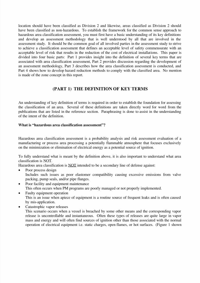
• Catastrophic vapor releasesThis scenario occurs when a vessel is breached by some other means and the corresponding vapor
release is uncontrollable and instantaneous. Often these types of releases are quite large in vapor
mass and energy and will often find sources of ignition other than those associated with the normaloperation of electrical equipment i.e. static charges, open flames, or hot surfaces. (Figure 1 shown
8/3/2019 A Common Sense Approach to Hazardous Area Classification for Electronic Instrumentation
http://slidepdf.com/reader/full/a-common-sense-approach-to-hazardous-area-classification-for-electronic-instrumentation 3/12
below illustrates the expansive nature of a catastrophic release of hydrogen from a closedcontainment system. Dispersion model derived from PHAST. PHAST is dispersion modeling software licensed
through Det Norske Veritas Risk Management Software Division).
What are “Hazardous Area Classes”?
Hazardous Areas are divided into three distinct classes that are totally dependent on the type of materialthat is encountered in the process. They are described as follows:
Class I Areas
These are locations in which flammable gases and/or vapors are or may be present in the air in quantities sufficient
to produce an explosion or ignitable mixture. In Class I Areas that utilize the division concept methodology there
are two distinct divisions that are predicated on the operational interpretation of the words normal vs. abnormal and
frequent vs. infrequent. The formal definitions are described as follows:
Division 1 - These are locations in which ignitable concentrations of flammable gases or vapors can exist:
• under normal operating conditions.
• frequently because of maintenance or repair.
• because of frequent leakage.
• below grade where adequate ventilation does not exist.
• when releases from faulty operations of process equipment results in the simultaneous failure of electrical
equipment.
Division 2 - These are locations in which ignitable concentrations of flammable gases or vapors can exist due to:
• failure of closed containment systems.
• abnormal operation or failure of processing equipment.
• abnormal operation or failure of ventilation equipment.
• area is adjacent a division 1 location.
FIGURE 1 CATASTROPHIC H2
RELEASE
8/3/2019 A Common Sense Approach to Hazardous Area Classification for Electronic Instrumentation
http://slidepdf.com/reader/full/a-common-sense-approach-to-hazardous-area-classification-for-electronic-instrumentation 4/12
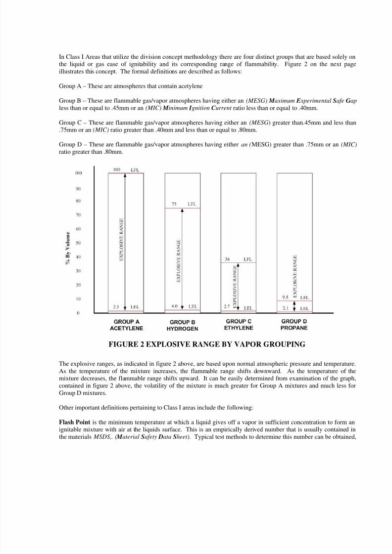
In Class I Areas that utilize the division concept methodology there are four distinct groups that are based solely on
the liquid or gas ease of ignitability and its corresponding range of flammability. Figure 2 on the next page
illustrates this concept. The formal definitions are described as follows:
Group A – These are atmospheres that contain acetylene
Group B – These are flammable gas/vapor atmospheres having either an (MESG) M aximum E xperimental Safe Gap
less than or equal to .45mm or an (MIC) M inimum I gnition C urrent ratio less than or equal to .40mm.
Group C – These are flammable gas/vapor atmospheres having either an (MESG) greater than.45mm and less than
.75mm or an (MIC) ratio greater than .40mm and less than or equal to .80mm.
Group D – These are flammable gas/vapor atmospheres having either an (MESG) greater than .75mm or an (MIC)
ratio greater than .80mm.
The explosive ranges, as indicated in figure 2 above, are based upon normal atmospheric pressure and temperature.
As the temperature of the mixture increases, the flammable range shifts downward. As the temperature of the
mixture decreases, the flammable range shifts upward. It can be easily determined from examination of the graph,
contained in figure 2 above, the volatility of the mixture is much greater for Group A mixtures and much less forGroup D mixtures.
Other important definitions pertaining to Class I areas include the following:
Flash Point is the minimum temperature at which a liquid gives off a vapor in sufficient concentration to form an
ignitable mixture with air at the liquids surface. This is an empirically derived number that is usually contained in
the materials MSDS,. ( M aterial Safety Data Sheet). Typical test methods to determine this number can be obtained,
FIGURE 2 EXPLOSIVE RANGE BY VAPOR GROUPING
8/3/2019 A Common Sense Approach to Hazardous Area Classification for Electronic Instrumentation
http://slidepdf.com/reader/full/a-common-sense-approach-to-hazardous-area-classification-for-electronic-instrumentation 5/12
depending on the liquids viscosity, from the either the Tag or Pensky-Martens Closed Cup Tester. (See NFPA 30
section 1.7.4 for more detail).
A flammable liquid is any liquid that has a closed-cup flash point below 100o F.
A combustible liquid is any liquid that has a closed-cup flash point at or above 100o F.
Classes of Combustible Liquids include Class II which is any liquid with a flash point greater than 100oF and lessthan or equal to 140
oF and Class III liquids which are any liquids with a flash point greater than 140
oF. Class III
liquids are further divided as either a Class IIIA liquids, which is a liquid with a flash point greater than 140 oF and
less than or equal to 200oF, or a Class IIIB liquids, which is a liquid with a flash point greater than 200 oF. Some of
the greatest confusion lies in how these types of materials, specifically Class III liquids, are treated when it comes to
the assessment of an areas classification. The API ( American Petroleum I nstitute) in RP500 section 5.2.4 basically
says to disregard the classification of areas that are processing Class III liquids even if processed above their
respective flash points. The NFPA ( N ational Fire Protection Association) specifically NFPA 497 basically gives no
credence to this issue especially when it comes to the definition of the extent of classified areas in section 3.8.
OSHA (Occupational Safety and H ealth Administration) states in 1910.106 (a)(18)(iii) that when a combustible
liquid is heated to within 30oF of its flash point, it shall be handled in accordance with the requirements of the next
lower class of liquids. So now the question becomes how do you handle the combustible class of liquids. First of
all, if the material is a combustible liquid that is not heated to within 30oF of its flash point, then the consensus is to
not require the area to be classified. In other-words, its contribution to the assessment of a hazardous area can beignored. The other and most often encountered scenario is when the combustible liquid is heated within the process
to several hundred degrees in excess of its flash point. This is typical in refinery and petrochemical operations in the
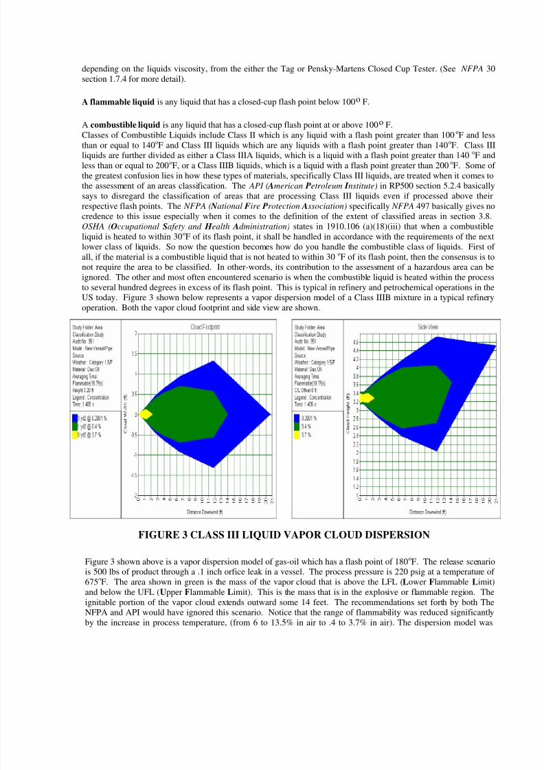
US today. Figure 3 shown below represents a vapor dispersion model of a Class IIIB mixture in a typical refinery
operation. Both the vapor cloud footprint and side view are shown.
Figure 3 shown above is a vapor dispersion model of gas-oil which has a flash point of 180oF. The release scenario
is 500 lbs of product through a .1 inch orfice leak in a vessel. The process pressure is 220 psig at a temperature of
675oF. The area shown in green is the mass of the vapor cloud that is above the LFL (Lower Flammable Limit)
and below the UFL (Upper Flammable Limit). This is the mass that is in the explosive or flammable region. The
ignitable portion of the vapor cloud extends outward some 14 feet. The recommendations set forth by both The
NFPA and API would have ignored this scenario. Notice that the range of flammability was reduced significantly
by the increase in process temperature, (from 6 to 13.5% in air to .4 to 3.7% in air). The dispersion model was
FIGURE 3 CLASS III LIQUID VAPOR CLOUD DISPERSION
8/3/2019 A Common Sense Approach to Hazardous Area Classification for Electronic Instrumentation
http://slidepdf.com/reader/full/a-common-sense-approach-to-hazardous-area-classification-for-electronic-instrumentation 6/12
derived from PHAST. PHAST is a dispersion modeling software licensed through Det Norske Veritas Risk
Management Software Division.
Class II Areas
These are locations that are hazardous because of the presence of combustible dust. A combustible dust is defined
as any solid material 420 microns or less in diameter that presents a fire or explosion hazard when dispersed in air.
Like Class I areas, Class II areas are also divided into two distinct divisions that again depend on operational
interpretation of the words normal vs. abnormal. The formal definitions are described as follows:
Division 1 is a location where combustible dust is present in the air
• under normal operating conditions in quantities sufficient to produce an explosive or ignitable mixture.
• is electrically conductive. Dusts are considered to be electrically conductive if the electrical resistivity of
the solid material from which the dust is formed has a value of less than 105 ohm-cm.
• releases from faulty operation of process equipment results in the simultaneous failure of electrical
equipment causing the electrical equipment to become a source of ignition.
Division 2 is a location where combustible dust
• is present in the air only under abnormal operating conditions in quantities sufficient to produce an
explosive or ignitable mixture.
• accumulations are normally insufficient to interfere with the normal operation of electrical equipment or
other apparatus, but combustible dust could be in suspensions in the air due to infrequent malfunctions of
process equipment.
• accumulations on, in, or in the vicinity of the electrical equipment could be sufficient to interfere with the
safe dissipation of heat from electrical equipment, or could be ignitable by abnormal operation or failure
of electrical equipment.
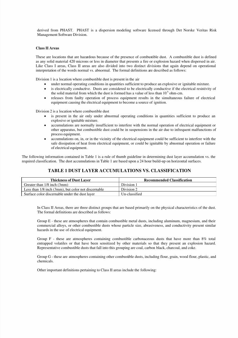
The following information contained in Table 1 is a rule of thumb guideline in determining dust layer accumulation vs. the
required classification. The dust accumulations in Table 1 are based upon a 24 hour build-up on horizontal surfaces.
TABLE 1 DUST LAYER ACCUMULATIONS VS. CLASSIFICATION
Thickness of Dust Layer Recommended Classification
Greater than 1/8 inch (3mm) Division 1
Less than 1/8 inch (3mm), but color not discernable Division 2
Surface color discernable under the dust layer Un-classified
In Class II Areas, there are three distinct groups that are based primarily on the physical characteristics of the dust.
The formal definitions are described as follows:
Group E - these are atmospheres that contain combustible metal dusts, including aluminum, magnesium, and their
commercial alloys, or other combustible dusts whose particle size, abrasiveness, and conductivity present similar
hazards in the use of electrical equipment.
Group F - these are atmospheres containing combustible carbonaceous dusts that have more than 8% total
entrapped volatiles or that have been sensitized by other materials so that they present an explosion hazard.
Representative combustible dusts that fall into this grouping are coal, carbon black, charcoal, and coke.
Group G - these are atmospheres containing other combustible dusts, including flour, grain, wood flour, plastic, and
chemicals.
Other important definitions pertaining to Class II areas include the following:
8/3/2019 A Common Sense Approach to Hazardous Area Classification for Electronic Instrumentation
http://slidepdf.com/reader/full/a-common-sense-approach-to-hazardous-area-classification-for-electronic-instrumentation 7/12
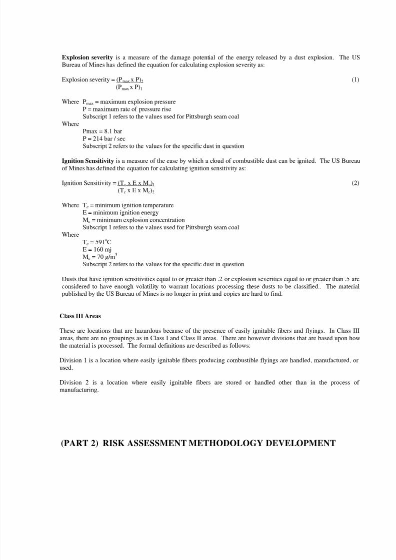
Explosion severity is a measure of the damage potential of the energy released by a dust explosion. The US
Bureau of Mines has defined the equation for calculating explosion severity as:
Explosion severity = (Pmax x P)2 (1)
(Pmax x P)1
Where Pmax = maximum explosion pressure
P = maximum rate of pressure rise
Subscript 1 refers to the values used for Pittsburgh seam coal
Where
Pmax = 8.1 bar
P = 214 bar / sec
Subscript 2 refers to the values for the specific dust in question
Ignition Sensitivity is a measure of the ease by which a cloud of combustible dust can be ignited. The US Bureau
of Mines has defined the equation for calculating ignition sensitivity as:
Ignition Sensitivity = (Tc x E x Mc)1 (2)
(Tc x E x Mc)2
Where Tc = minimum ignition temperature
E = minimum ignition energy
Mc = minimum explosion concentration
Subscript 1 refers to the values used for Pittsburgh seam coal
Where
Tc = 591oC
E = 160 mj
Mc = 70 g/m3
Subscript 2 refers to the values for the specific dust in question
Dusts that have ignition sensitivities equal to or greater than .2 or explosion severities equal to or greater than .5 are
considered to have enough volatility to warrant locations processing these dusts to be classified.. The material
published by the US Bureau of Mines is no longer in print and copies are hard to find.
Class III Areas
These are locations that are hazardous because of the presence of easily ignitable fibers and flyings. In Class III
areas, there are no groupings as in Class I and Class II areas. There are however divisions that are based upon how
the material is processed. The formal definitions are described as follows:
Division 1 is a location where easily ignitable fibers producing combustible flyings are handled, manufactured, or
used.
Division 2 is a location where easily ignitable fibers are stored or handled other than in the process of
manufacturing.
(PART 2) RISK ASSESSMENT METHODOLOGY DEVELOPMENT
8/3/2019 A Common Sense Approach to Hazardous Area Classification for Electronic Instrumentation
http://slidepdf.com/reader/full/a-common-sense-approach-to-hazardous-area-classification-for-electronic-instrumentation 8/12
A risk assessment methodology must be developed prior to beginning the actual area classification
assessment itself. This methodology sets the ground-rules by which the assessment is conducted. Thedeliverables presented at the completion of the assessment methodology are as follows:
• Key members of the assessment team are identified along with their respective roles and
responsibilities required to support the assessment process. Typically this core team will consistof an operations representative, a mechanical integrity representative, the individual who is
conducting the actual assessment, and a process engineer.
• The assessment concept point source vs. the blanket classification will be determined.
• All potential point source of emissions will be identified. Point sources are process equipment
that continuously or intermittently release flammable vapors into the atmosphere during routinemodes of operation. Typical equipment that should be considered are:
o Mechanical pumps seals
o Valve packing (typically modulating service control valves only)
o Overpressure protection devices such as relief valves, rupture discs, and conservationsvents
o Filters
o Compressor seals
o Process drains and vents
• Operationally define such terms as normal vs. abnormal and frequent vs. infrequent
• Determine how to address the following scenarios:
o extent of classified areas that extend beyond unit battery limits
o areas where sources of ignition other than electrical are present under normal operatingconditions
o areas where pipe bridges and racks either cross or are adjacent roadways
o impact of facility or unit operational historyo discovery of errors and omissions in documentation (typical documentation consists of
scaled plot plans, PFD’s ( process f low d iagrams) , P&ID’s ( piping and instrumentation
d iagrams) Unit SOP’s (standard o perating procedures ) and MSDS’s
• Determine how the various codes and standards writing organizations will apply. Typically
NFPA is used for all petrochemical applications and API is used for refinery applications.
• Determine whether the division or zone concept will be utilized. Typically the division conceptis used in the US and the zone concept is used in Canada and Europe.
• Determine who is the authority that has jurisdiction.
(PART 3) AREA CLASSIFICATION ASSESSMENT
8/3/2019 A Common Sense Approach to Hazardous Area Classification for Electronic Instrumentation
http://slidepdf.com/reader/full/a-common-sense-approach-to-hazardous-area-classification-for-electronic-instrumentation 9/12
Once the risk assessment methodology is developed then the actual process of classifying the area is
ready to begin. A typical assessment study will include the basic 7 step process as follows:
Step 1 Obtain the required documentation that was determined from the assessment methodology.PFD’s provide information about the process stream such as pressures, temperatures, flow ratesand stream compositions. Plot plans will become the backgrounds used for the area
classification plan drawings. MSDS’s are the source of process information about each
component in the process stream. P&ID’s provide a lower level view of the process for
equipment identification and process arrangements.Step 2 Field survey the area in question to determine the accuracy of the plot plans and verify location
of all point sources of emissions. The plot plans will serve as the background for the area
classification plan drawings. Area classification background drawings should show all vessels,tanks, pumps, sumps, compressors, building structures, dikes, partitions, levees, and other items
that might impact the dispersion of the process material. These drawings should also indicate the
prevailing wind direction.Step 3 Determine the extent of the classified area that surrounds each point source of emission. This
will determine the role that each point source will play in the overall composite area
classification diagram. The extent of classification diagrams should come from The NFPA 497
for petrochemical applications, API RP500 for petroleum refinery applications, and/or gasdispersion modeling software tools. Gas/vapor dispersion modeling software should be utilized
when one out of the two scenarios exist. 1) Extreme process conditions are encountered such as
large flow rates > 250 gallons/minute (gpm), pressures > 275 lbs/in2
( psig), and liquids with avapor pressure > 70 lbs/in2 absolute (psia) at operating temperature. 2) Combustible Liquids are
heated to temperatures > 100oF of their respective flash point.Step 4 Develop the composite area classification plan drawing that embellishes the contribution of all
point sources.
Step 5 Develop elevation drawings to provide clarity where there are emissions sources located inmultilevel process structures. A plan view will be required for each level in the process
structure.
Step 6 Conduct the compliance auditStep 7 Create a detailed assessment report that documents the following information:
• The rationale used to classify the areas.
• The critical process material information usually obtained from MSDS’s.
• A detailed listing of all point sources of emissions that appear on the drawings.
• Special out of the ordinary exceptions that were taken when classifying a particular location
• The results or findings obtained from the compliance audit
All area classification documentation should be placed under the protection of the facilities MOC
( management o f change) process control. As modifications are made to the facility these documents
should be reviewed to verify the impact of these modifications.
(PART 4) METHODS OF PROTECTION AND HAZARD REDUCTION
8/3/2019 A Common Sense Approach to Hazardous Area Classification for Electronic Instrumentation
http://slidepdf.com/reader/full/a-common-sense-approach-to-hazardous-area-classification-for-electronic-instrumentation 10/12
Hazard reduction is the means by which a facility reduces the probably or risk of significant property
damage and/or loss of life as the result of an explosion of fire. It helps insure that the installation of electrical equipment in a hazardous location does not significantly raise the risk or probability of an
explosion or fire. This is the point where steps are taken to provide compliance with the areaclassification assessment.
METHODS OF PROTECTION IN CLASS I AREAS
Physically isolate the hazard Place or relocate the normal arc producing electrical devices to a non-hazardous area. This is an attractive option when approved equipment for the classified area is not
readily or commercially available.
Confine the explosion This is the most common and widely accepted method of protection. It deploys
the use of vendor certified, through listing or labeling the device, as explosion proof. Explosion proof
means that the device enclosure is designed and tested in a manner that guarantees if a flammable vaporenters the enclosure and is ignited by an electrical arc or hot surface within the enclosure, the resulting
explosion is contained within the enclosure. The electrical apparatus contained within the enclosure
should still be operational.
Energy Limiting This concept is known as intrinsic safety, which prevents ignition by limiting the
released energy resulting from wiring and component failures or faults. UL (Underwriters Laboratory)
listed intrinsically safe electrical devices are incapable of releasing enough energy under normal orabnormal conditions, to cause ignition of a specific hazardous atmosphere in its most easily ignitable
concentrations.
Hermetically sealed This type of protection insures that the arc or heat producing devices are sealed
against the intrusion of the hazardous vapor.
Purging and Pressurization Pressurization is the process of supplying an enclosure with a protective
gas with or without continuous flow to prevent the entrance of a flammable vapor, a combustible dust,or an ignitable fiber. Purging is the process of supplying an enclosure with a protective gas at a
sufficient flow and positive pressure to reduce the concentration of any flammable vapor initially present
to a safe level.
TYPES OF PRESSURIZED SYSTEMS
Type X reduces the classification within a protected enclosure from Division 1 to un-classified. The design
requirements for a Type X purge system is as follows:• Maintain a positive pressure > .1 inch of water with equipment energized.
• Exchange 4 enclosure volumes of purge gas before energizing components with a required interlock.
• Interlock is required to remove power from internal electrical components in the enclosure when the purge
pressure falls below .1 inch of water.
• Must remove power from enclosure when enclosure is opened
• The pressure alarm must be located in a continuously attended area.
Type Y reduces the classification within a protected enclosure from Division 1 to Division 2.
8/3/2019 A Common Sense Approach to Hazardous Area Classification for Electronic Instrumentation
http://slidepdf.com/reader/full/a-common-sense-approach-to-hazardous-area-classification-for-electronic-instrumentation 11/12
Type Z reduces the classification within the protected enclosure from Division 2 to unclassified. The design
requirements for a Type Y or Z purge system is as follows:
• Maintain positive pressure greater than or equal to.1 inch of water with equipment energized.
• Exchange 4 enclosure volumes of purge gas before energizing components (no interlock required)
• Must detect failure of purge system with alarm.
Oil Immersion This method of protection is where the arc producing or heat generating devices areimmersed in oil thereby eliminating the intrusion of potentially hazardous vapors. This method can onlybe used for Division 2 areas.
METHODS OF PROTECTION IN CLASS II AREAS
Physically isolate the hazard (same as for Class I areas)
Utilize Dust Ignition Proof Equipment The use of dust ignition proof equipment means two things. 1)
The enclosure is dust-tight, and 2) the enclosure is constructed so that heat generated inside will not
ignite a dust layer on or a combustible cloud surrounding the enclosure.
Pressurization There are no levels of protection for as noted for Class I areas you must follow the
requirements for purging as noted in NFPA 496.
Energy Limiting Is the same level of protection applies as did for Class I areas.
METHODS OF PROTECTION IN CLASS III AREAS
The methods of protection for Class III areas employ the same methods that were utilized for Class II
areas. The basic requirement is to make use of dust-tight enclosure for all normal arc-producingelectrical devices.
CONCLUSION
A common sense approach to area classification assessment is to follow the basic 4-part process asoutlined in this paper. First, develop a risk assessment methodology that lays out the framework from
which the assessment will be conducted. Second, obtain a common understanding of all pertinent terms
and their corresponding definitions that impact area classification assessment. Third, perform the
assessment and compliance audit providing all drawings and reports. Fourth, determine and implementthe proper methods of hazard reduction. This approach will help to insure that the installation of
electrical equipment in hazardous classified areas will not increase the probability of an explosion or firewhile at the same time mitigating capital waste trying to comply with conservatively rated hazardous
areas.
REFERENCES
8/3/2019 A Common Sense Approach to Hazardous Area Classification for Electronic Instrumentation
http://slidepdf.com/reader/full/a-common-sense-approach-to-hazardous-area-classification-for-electronic-instrumentation 12/12
Korver, W.O.E, “Part 1 Fundamentals” Electrical Safety in Flammable Gas / Vapor Laden Atmospheres,
1st
Edition, William Andrews Publishing, Norwich, New York, 2001 Pages 6,7, and 8.
NFPA 30, Flammable and Combustible Liquids Code, 2000 Ed, NFPA, Quincy, MA, 2000
NFPA 496, Standard for Purged and Pressurized Enclosures for Electrical Equipment, 1998 Ed, NFPA,Ouincy, MA, 1998
NFPA 497, Recommended Practice for the Classification of Flammable Liquids, Gases or Vapors and of
Hazardous (Classified) Locations for Electrical Installations in Chemical Process Areas, 1997 Ed,
NFPA, Ouincy, MA, 1997
NFPA 499, Recommended Practice for the Classification of Combustible Dusts and of Hazardous
(Classified) Locations for Electrical Installations in Chemical Process Areas, 1997 Ed, NFPA, Ouincy,
MA, 1997
ANSI / API PR5000, Recommended Practice for Classification of Locations for Electrical Installationsat Petroleum Facilities Classified as Class I, Division 1 and Division 2, 2nd Ed, API Publishing Services,
Washington, D.C., 1997
ISA-12.10, Area Classification in Hazardous (Classified) Dust Locations, ISA, Research Triangle Park,North Carolina, 1988
ISA-RP12.4, Pressurized Enclosures, ISA, Research Triangle Park, North Carolina, 1996
Johnston, James, “A Common-Sense Approach to Hazardous Area Classification Assessment”,Instrumentation Symposium for The Process Industries Texas A&M University, College Station,TexasJanuary, 2001.
Cashdollar Kenneth, Hertzberg Martin, Conti Ronald, “RI-8988 Bureau of Mine Report of Investigations / 1985” Electrical Ignition Energies and Thermal Autoignition Temperatures for
Evaluating Explosion Hazards of Dusts, United States Dept of the Interior, 1985
Early Mark, P.E. (editor in chief), National Electrical Code Handbook, 9th
Ed, NFPA, Quincy, MA.2002