Embed Size (px)
Citation preview
A COMBINED SHEAR=COMPRESSION DEVICE TO MEASURE CONCRETE=TO=CONCRETE BONDING
by F. Saucier, J. Bastien, M. Pigeon and M. Fafard
In many instances, deteriorated concrete structures could be economically repaired if a thin concrete overlay could be used. However, experience has shown that debonding often occurs, sometimes after only few months of service. In fact, the actual knowledge of the new-to-old concrete bonding mechanism is very limited and needs to be improved before durable repairs can be ob- tained in every case.
To study the bonding mechanism, the first task is to choose a testing procedure to evaluate the mechanical strength of a concrete-to-concrete joint. Many procedures have already been proposed, but it was considered neces- sary, for research purposes, to develop a new testing device working with small concrete specimens and designed to minimize the influence of stress concentrations. Because our research program on the durability of bonding involved a large number of specimens, special attention was given to obtaining an overall testing time (fabricating and preparing specimens, testing and cleaning) as short as possible. The procedure and the device developed to fit these needs are described in this paper following a discussion of some of the classical methods of testing concrete-toconcrete bonding.
COMMON BONDING EVALUM’ION TECHNIQUES
The components of a given test method can be considered in many ways. Besides rapidity and accuracy, the ‘space- efficiency’ of the concrete specimens is also an important factor, particularly for a large test program. In fact, the volume of the specimens becomes a determining factor when the space available to simulate accelerated aging is limited. In this case, we wanted to optimize the use of a freezing and thawing machine and a wetting and drying setup. An interesting way to evaluate the ‘space-efficiency’ of a specimen is to calculate the ratio between the bonded surface submitted to the test loading and the specimen
F. Saucier is Graduate Student, J Bastien is GmduuteStudent, M. Pigeon is Professor and M. Fafard is Assistant Professor, Lava1 University, Quebec, CaMda.
Fig. 1-Illustration of the space efficiency concept for two specimens utilized for bond testing
volume, as illustrated in Fig. 1. Using this ratio, it is clear that flexure beams with a bonded joint in their center are not very efficient because only a small fraction of the bonded joint is submitted to the maximum tensile stress and most of the specimen’s volume is only the ‘filling’ necessary to obtain flexure. For instance, with 75 x 100 x 400-mm beams with a bonded plane in the center, even if half of the bonded plane is tested, the space-efficiency ratio is 1:80 (a surface of 37.5 cm’ and a volume of 3000 cm3 ).
In bonding tests, the preparation of the surface to be bonded is very important. Unfortunately, many proposed procedures are too empirical to obtain repetitive results. The use of a cast surface to test new to old concrete bonding is an easily reproduced surface preparation but is rarely representative of repaired surfaces.
Anderson and DeVries’ have explained clearly the dominant influence of stress singularities at the edge of test specimens on the mechanical strength measured. Most of the actual testing techniques should be critically reviewed considering this phenomenon and using the fracture mechanics concepts. This would help to improve out under- standing of the failure of concrete repairs.
Thus, the problem is to obtain a test method addressing all these needs: rapidity, accuracy, space-efficiency of specimens, surface reproducibility and reduced influence of stress concentrations. Many testing procedures have been
50 September/Oetober 1981
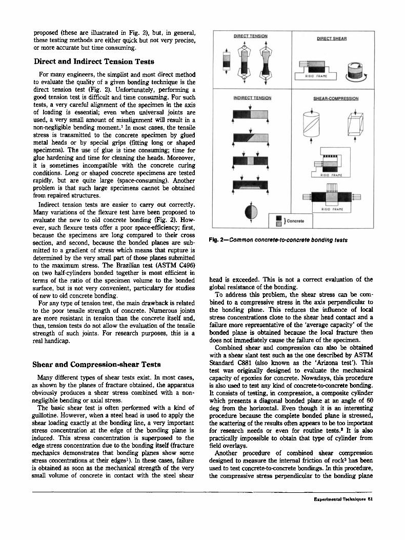
proposed (these are illustrated in Fig. 2), but, in general, these testing methods are either quick but not very precise, or more accurate but time consuming.
Direct and Indirect Tension Tests For many engineers, the simplist and most direct method
to evaluate the quality of a given bonding technique is the direct tension test (Fig. 2). Unfortunately, performing a good tension test is difficult and time consuming. For such tests, a very careful alignment of the specimen in the axis of loading is essential; even when universal joints are used, a very small amount of misalignment will result in a non-negligible bending m0ment.I In most cases, the tensile stress is transmitted to the concrete specimen by glued metal heads or by special grips (fitting long or shaped specimens). The use of glue is time consuming; time for glue hardening and time for cleaning the heads. Moreover, it is sometimes incompatible with the concrete curing conditions. Long or shaped concrete specimens are tested rapidly, but are quite large (spaceconsuming). Another problem is that such large specimens cannot be obtained from repaired structures.
Indirect tension tests are easier to carry out correctly. Many variations of the flexure test have been proposed to evaluate the new to old concrete bonding (Fig. 2). How- ever, such flexure tests offer a poor space-efficiency; first, because the specimens are long compared to their cross section, and second, because the bonded planes are sub- mitted to a gradient of stress which means that rupture is determined by the very small part of those planes submitted to the maximum stress. The Brazilian test (ASTM (296) on two half-cylinders bonded together is most efficient in terms of the ratio of the specimen volume to the bonded surface, but is not very convenient, particulary for studies of new to old concrete bonding.
For any type of tension test, the main drawback is related to the poor tensile strength of concrete. Numerous joints are more resistant in tension than the concrete itself and, thus, tension tests do not allow the evaluation of the tensile strength of such joints. For research purposes, this is a real handicap.
Shear and Compression-shear Tests Many different types of shear tests exist. In most cases,
as shown by the planes of fracture obtained, the apparatus obviously produces a shear stress combined with a non- negligible bending or axial stress.
The basic shear fest is often performed with a kind of guillotine. However, when a steel head is used to apply the shear loading exactly at the bonding line, a very important stress concentration at the edge of the bonding plane is induced. This stress concentration is superposed to the edge stress concentration due to the bonding itself (fracture mechanics demonstrates that bonding planes show some stress concentrations at their edges’). In these cases, failure is obtained as soon as the mechanical strength of the very small volume of concrete in contact with the steel shear
Flg. 2-common concrete-to-concrete bonding tests
head is exceeded. This is not a correct evaluation of the global resistance of the bonding.
To address this problem, the shear stress can be com- bined to a compressive stress in the axis perpendicular to the bonding plane. This reduces the influence of local stress concentrations close to the shear head contact and a failure more representative of the ‘average capacity’ of the bonded plane is obtained because the local fracture then does not immediately cause the failure of the specimen.
Combined shear and compression can also be obtained with a shear slant test such as the one described by ASTM Standard (381 (also known as the ‘Arizona test’). This test was originally designed to evaluate the mechanical capacity of epoxies for concrete. Nowadays, this procedure is also used to test any kind of concrete-toconcrete bonding. It consists of testing, in compression, a composite cylinder which presents a diagonal bonded plane at an angle of 60 deg from the horizontal. Even though it is an interesting procedure because the complete bonded plane is stressed, the scattering of the results often appears to be too important for research needs or even for routine tests.* It is also practically impossible to obtain that type of cylinder from field overlays.
Another procedure of combined shear compression designed to measure the internal friction of rock3 has been used to test concrete-toconcrete bondings. In this procedure, the compressive stress perpendicular to the bonding plane
Experimental ‘lbchnlquer 61
is applied by a hydraulic jack or by a mechanical tightening system. As the shear loading increases up to failure, the compressive load tends to increase because the deforma- tion of concrete is restrained by a rigid setup. The compres- sive load at failure is then unknown and can vary from test to test. The results of such tests cannot therefore be compared. The necessity of specimen pre-molding in high strength plaster is also time-consuming.
Torsional shear tests have also been reported but little information is available. As in flexure tests, the bonded plane is submitted to a gradient of stress and failure is determined by only the small ring-shaped area submitted to the maximum shear stress. A simple procedure was recently proposed to obtain an almost pure torsional shear stress on laboratory specimen^,^ i.e., without secondary axial or bending stress. This procedure requires specimens with a relatively low space efficiency. Torsional shear tests probably represent a valuable technique for field testing on in-situ cores.
Proposed Procedure
Any test will always have advantages and disadvantages. The main interest of the device that will be described is to offer a balanced set of qualities for the purposes of research on the durability of new to old concrete bonding. We have chosen to design a compression-shear device because a large bonded surface can be stressed with the use of relatively small specimens. This test meets our requirement of specimen space efficiency for optimum use of accelerated aging machines. It is also characterized by tightening and compressive loads maintained constant up to failure, a reduced stress concentration in the specimens at the contact area with the loading heads, and a short test-to-test time.
MODELING OF THE DEVICE BY THE FINITE-ELEMENT METHOD
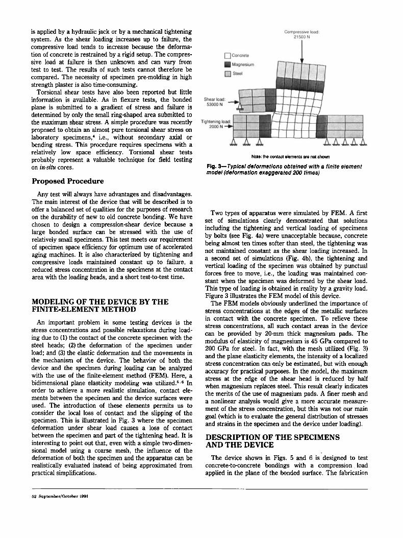
An important problem in some testing devices is the stress concentrations and possible relaxations during load- ing due to (1) the contact of the concrete specimen with the steel heads; (2) the deformation of the specimen under load; and (3) the elastic deformation and the movements in the mechanism of the device. The behavior of both the device and the specimen during loading can be analyzed with the use of the finite-element method (FEM). Here, a bidimensional plane elasticity modeling was uti l i~ed.~. In order to achieve a more realistic simulation, contact ele- ments between the specimen and the device surfaces were used. The introduction of these elements permits us to consider the local loss of contact and the slipping of the specimen. This is illustrated in Fig. 3 where the specimen deformation under shear load causes a loss of contact between the specimen and part of the tightening head. It is interesting to point out that, even with a simple two-dimen- sional model using a coarse mesh, the influence of the deformation of both the specimen and the apparatus can be realistically evaluated instead of being approximated from practical simplifications.
Note: the contact elements are not shown
Fig. 3-Typical deformations obtained with a finite element model (deformation exaggerated 200 times)
Two types of apparatus were simulated by FEM. A first set of simulations clearly demonstrated that solutions including the tightening and vertical loading of specimens by bolts (see Fig. 4a) were unacceptable because, concrete being almost ten times softer than steel, the tightening was not maintained constant as the shear loading increased. In a second set of simulations (Fig. 4b), the tightening and vertical loading of the specimen was obtained by punctual forces free to move, i.e., the loading was maintained con- stant when the specimen was deformed by the shear load. This type of loading is obtained in reality by a gravity load. Figure 3 illustrates the FEM model of this device.
The FEM models obviously underlined the importance of stress concentrations at the edges of the metallic surfaces in contact with the concrete specimen. To relieve these stress concentrations, all such contact areas in the device can be provided by 20-mm thick magnesium pads. The modulus of elasticity of magnesium is 45 GPa compared to 200 GPa for steel. In fact, with the mesh utilized (Fig. 3) and the plane elasticity elements, the intensity of a localized stress concentration can only be estimated, but with enough accuracy for practical purposes. In the model, the maximum stress at the edge of the shear head is reduced by half when magnesium replaces steel. This result clearly indicates the merits of the use of magnesium pads. A finer mesh and a nonlinear analysis would give a more accurate measure- ment of the stress concentration, but this was not our main goal (which is to evaluate the general distribution of stresses and strains in the specimen and the device under loading).
DESCRIPTION OF THE SPECIMENS AND THE DEVICE
The device shown in Figs. 5 and 6 is designed to test concrete-to-concrete bondings with a compression , load applied in the plane of the bonded surface. The fabrication
62 SepCember/October 1991
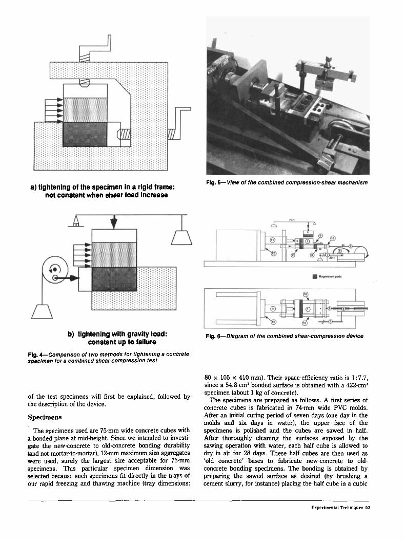
Fig. 5- View of the combined compression-shear mechanism a) tightening of the specimen in a rigid frame:
not constant when shear load increase
b) tightening with gravity load: constant up to failure
Flg. 4-Comparison of two methods for tlghtening a concrete specimen for a combined shear-compression test
of the test specimens will first be explained, followed by the description of the device.
Specimens
The specimens used are 75-mm wide concrete cubes with a bonded plane at mid-height. Since we intended to investi- gate the new-concrete to old-concrete bonding durability (and not mortar-to-mortar), 12-mm maximum size aggregates were used, surely the largest size acceptable for 75-mm specimens. This particular specimen dimension was selected because such specimens fit directly in the trays of our rapid freezing and thawing machine (tray dimensions:
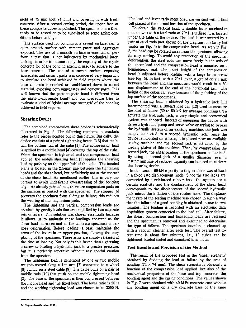
Fig. 6- Diagram of the combined shear-compression device
80 x 105 x 410 mm). Their space-efficiency ratio is 1:7.7, since a 54.8-cm’ bonded surface is obtained with a 422-cm2 specimen (about 1 kg of concrete).
The specimens are prepared as follows. A first series of concrete cubes is fabricated in 74-mm wide PVC molds. After an initial curing period of seven days (one day in the molds and six days in water), the upper face of the specimens is polished and the cubes are sawed in half. After thoroughly cleaning the surfaces exposed by the sawing operation with water, each half cube is allowed to dry in air for 28 days. These half cubes are then used as ‘old concrete’ bases to fabricate new-concrete to old- concrete bonding specimens. The bonding is obtained by preparing the sawed surface as desired (by brushing a cement slurry, for instance) placing the half cube in a cubic
Experimental Techniques 53
mold of 75 mm (not 74 mm) and covering it with fresh concrete. After a second curing period, the upper face of these composite cubes is polished. The specimens are then ready to be tested or to be submitted to some aging con- ditions before testing.
The surface used for bonding is a sawed surface, i.e., a quite smooth surface with cement paste an’d aggregate exposed. The use of a smooth surface is essential to per- form a test that is not influenced by mechanical inter- locking, in order to measure only the capacity of the repair concrete (or of the bonding agent, if used) to adhere to the base concrete. The use of a sawed surface exposing aggregates and cement paste was considered very important to simulate the bond achieved in field repairs where the base concrete is crushed or sand-blasted down to sound material, exposing both aggregates and cement paste. It is well known that the paste-to-paste bond is different from the paste-to-aggregate bond4 and our procedure tries to evaluate a kind of ‘global average strength’ of the bonding achieved in field repairs.
Shearing Device
The combined compression-shear device is schematically illustrated in Fig. 6. The following numbers in brackets refer to the pieces pointed out in this figure. Basically, the device consists of a pair of tightening heads [2-31 that main- tain the bottom half of the cube [l]. The compression load is applied by a mobile head [4] covering the top of the cube. When the specimen is tightened and the compression load applied, the mobile shearing head [5] applies the shearing load by pushing on the upper half of the cube. The bonded plane is located in the 2.5-mm gap between the tightening heads and the shear head, but definitively not at the contact of the shear head. As mentioned earlier, this is very im- portant to avoid undesirable overstressing of the bonding edge. As already pointed out, there are magnesium pads on the surfaces in contact with the specimen. The stopper [6] prevents the specimen from sliding at failure; this reduces the wearing of the magnesium pads.
The tightening and the vertical compression loads are obtained by gravity loads that are amplified by two separate sets of levers. This solution was chosen essentially because it allows us to maintain these loadings constant as the shear load increases and as the concrete specimen under- goes deformation. Before loading, a pawl maintains the arms of the levers in an upper position, allowing the easy placing of the specimen. These arms are simply released at the time of loading. Not only is this faster than tightening a screw or loading a hydraulic jack to a precise pressure, but it is perfectly repetitive without any special caution from the operator.
The tightening load is generated by one or two mobile weights moved along a 1-m arm [7] connected to a wheel [8] pulling on a steel cable [9]. The cable pulls on a pair of mobile rods [lo] that push on the mobile tightening head [2]. The base of the specimen is then compressed between the mobile head and the fixed head. The lever ratio is 20: 1 and the working tightening load was chosen to be 2000 N.
The load and lever ratio mentioned are verified with a load cell placed at the normal location of the specimen.
To obtain the vertical load, a double lever mechanism (not shown) with a total ratio of 70 : 1 is utilized; it is located under the table of the device. The load is transmitted by a pair of steel rods (not shown on the diagram for clarity but visible on Fig. 5) to the Compression head. As seen in Fig. 5, the head can be rotated away from the specimen, allowing its easy setting. To avoid any restriction of the specimen deformation, the steel rods can move freely in the axis of the shear load and the compression head is mounted on a hemispheric seat. The exact height of the compression head is adjusted before loading with a large brass screw (see Fig. 5). In fact, with a 70: 1 lever, a gap of only 1 mm between the head and the specimen would result in a 70- mm displacement at the end of the horizontal arm. The height of the cubes can vary because of the polishing of the top surface of the specimens.
The shearing load is obtained by a hydraulic jack [ l l ] instrumented with a 100-kN load cell [12] used to measure the load at failure (30 to 50 kN for average bondings). To activate the hydraulic jack, a very simple and economical system was adopted. Instead of equipping the device with its own hydraulic pump and servo-valve or trying to bypass the hydraulic system of an existing machine, the jack was simply connected to a second hydraulic jack. Since the device is mounted on wheels, it is placed near an available testing machine and the second jack is activated by the loading platen of this machine. Then, by compressing the second jack, the shear loading of the specimen is obtained. By using a second jack of a smaller diameter, even a testing machine of reduced capacity can be used to activate the shearing device.
In this case, a 90-kN capacity testing machine was utilized in a fixed rate displacement mode. Since the two jacks are connected by a reinforced rubber hose, the system has a certain elasticity and the displacement of the shear head corresponds to the displacement of the second hydraulic jack minus the inflation of the rubber hose. The displace- ment rate of the testing machine was chosen in such a way that the failure of a good bonding is obtained in one to two minutes. The loading is recorded with an electronic data acquisition system connected to the load cell. After failure, the shear, compression and tightening loads are released and the specimen is removed and examined to determine the type of failure. The specimen location is cleaned up with a vacuum cleaner after each test. The overall test-to- test time is about five minutes, i.e., 12 cubes can be tightened, loaded tested and examined in an hour.
Test Results and Recision of the Method
The result of the proposed test is the “shear strength” obtained by dividing the load at failure by the area of bonding (74 x 74 mm). The shear strength is obviously a function of the compression load applied, but also of the mechanical properties of the base and top concrete, the bonding agent and the curing conditions. The values shown in Fig. 7 were obtained with 40-MPa concrete cast without any bonding agent on a dry concrete base of the same
64 Seplember/October 1991
lo I I I I
I
0 1 2 3 4
Compresrlw told (UP.)
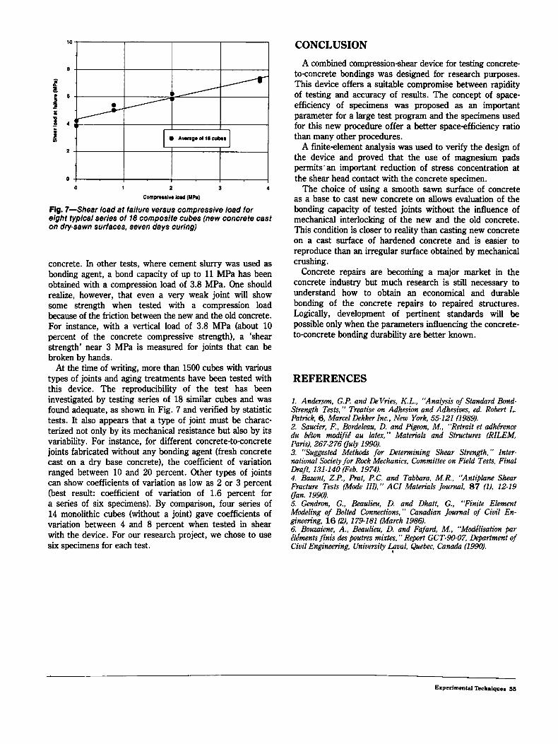
Fig. 7-Shear load at failure versus compressive load for elght typical series of 18 composite cubes (new concrete cast on dry-sawn surfaces, seven days curlng)
concrete. In other tests, where cement slurry was used as bonding agent, a bond capacity of up to 11 MPa has been obtained with a compression load of 3.8 MPa. One should realize, however, that even a very weak joint will show some strength when tested with a compression load because of the friction between the new and the old concrete. For instance, with a vertical load of 3.8 MPa (about 10 percent of the concrete compressive strength), a ‘shear strength’ near 3 MPa is measured for joints that can be broken by hands.
At the time of writing, more than 1500 cubes with various types of joints and aging treatments have been tested with this device. The reproducibility of the test has been investigated by testing series of 18 similar cubes and was found adequate, as shown in Fig. 7 and verified by statistic tests. It also appears that a type of joint must be charac- terized not only by its mechanical resistance but also by its variability. For instance, for different concrete-to-concrete joints fabricated without any bonding agent (fresh concrete cast on a dry base concrete), the coefficient of variation ranged between 10 and 20 percent. Other types of joints can show coefficients of variation as low as 2 or 3 percent (best result: coefficient of variation of 1.6 percent for a series of six specimens). By comparison, four series of 14 monolithic cubes (without a joint) gave coefficients of variation between 4 and 8 percent when tested in shear with the device. For our research project, we chose to use six specimens for each test.
CONCLUSION
A combined compression-shear device for testing concrete- to-concrete bondings was designed for research purposes. This device offers a suitable Compromise between rapidity of testing and accuracy of results. The concept of space- efficiency of specimens was proposed as an important parameter for a large test program and the specimens used for this new procedure offer a better space-efficiency ratio than many other procedures.
A finite-element analysis was used to verify the design of the device and proved that the use of magnesium pads permits‘ an important reduction of stress concentration at the shear head contact with the concrete specimen.
The choice of using a smooth sawn surface of concrete as a base to cast new concrete on allows evaluation of the bonding capacity of tested joints without the influence of mechanical interlocking of the new and the old concrete. This condition is closer to reality than casting new concrete on a cast surface of hardened concrete and is easier to reproduce than an irregular surface obtained by mechanical crushing.
Concrete repairs are becoming a major market in the concrete industry but much research is still necessary to understand how to obtain an economical and durable bonding of the concrete repairs to repaired structures. Logically, development of pertinent standards will be possible only when the parameters influencing the concrete- to-concrete bonding durability are better known.
REFERENCES
1. Ancierson, G.P. and DeVries, K.L., “Analysis of Standard Bond- Strength Tests,” Treatise on Adhesion and Adhesives, ed. Robert L. Patrick, 6, Marcel Dekker Inc.. New York, 55-121 (1989). 2. Saucier, F., Bordelenu, D. and Pigeon, M., “Retrait et adhhence du be‘ton modifie’ au latex,” Materials and Structures (RILEM, Pans), 267-276 (luly 1990). 3. “Suggested Methods for Determining Shear Strength,” Inter- national Society for Rock Mechanics, Committee on Field Tests, Final Draft, 131-140 (Feb. 1974). 4. Bazant, Z.P., Prat, P.C. and Tabbara, M.R., “Antiplane Shear Fracture Tests (Mode IIJ,” ACI Materials Journal, 87 (I) , 12-19 van. 1990). 5. Gendron, G., Beaulieu, D. and Dhatt, G., ‘<Finite Element Modeling of Bolted Connections,’’ Canadian Journal of Civil En- gineering, 16 (2). 179-181 (March 1986). 6. Bouzaiene, A. , Beaulieu, D. and Fafard, M., “Md’lisation par & h n t s finis des poutres mixtes, ” Report GCT-90-07, Department of Civil Engineering, University +ual, Quebec, Canada (I 990).
Experimental Teebniques 116