Embed Size (px)
Citation preview
1
10/7/2005
Kevin Covi
2005 IBM Power and Cooling Technology Symposium
A Combined Buck and Boost Converter for Single-Phase Power-Factor Correction
2
IBM High-End Power Hardware Development
10/7/2005
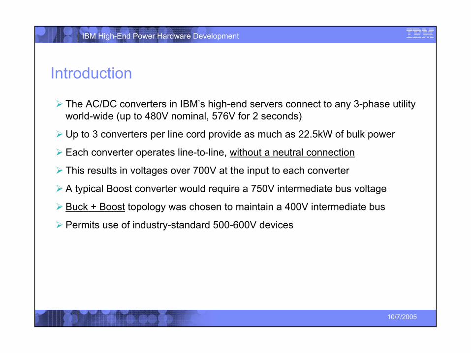
Introduction
The AC/DC converters in IBM’s high-end servers connect to any 3-phase utility world-wide (up to 480V nominal, 576V for 2 seconds)
Up to 3 converters per line cord provide as much as 22.5kW of bulk power
Each converter operates line-to-line, without a neutral connection
This results in voltages over 700V at the input to each converter
A typical Boost converter would require a 750V intermediate bus voltage
Buck + Boost topology was chosen to maintain a 400V intermediate bus
Permits use of industry-standard 500-600V devices
3
IBM High-End Power Hardware Development
10/7/2005
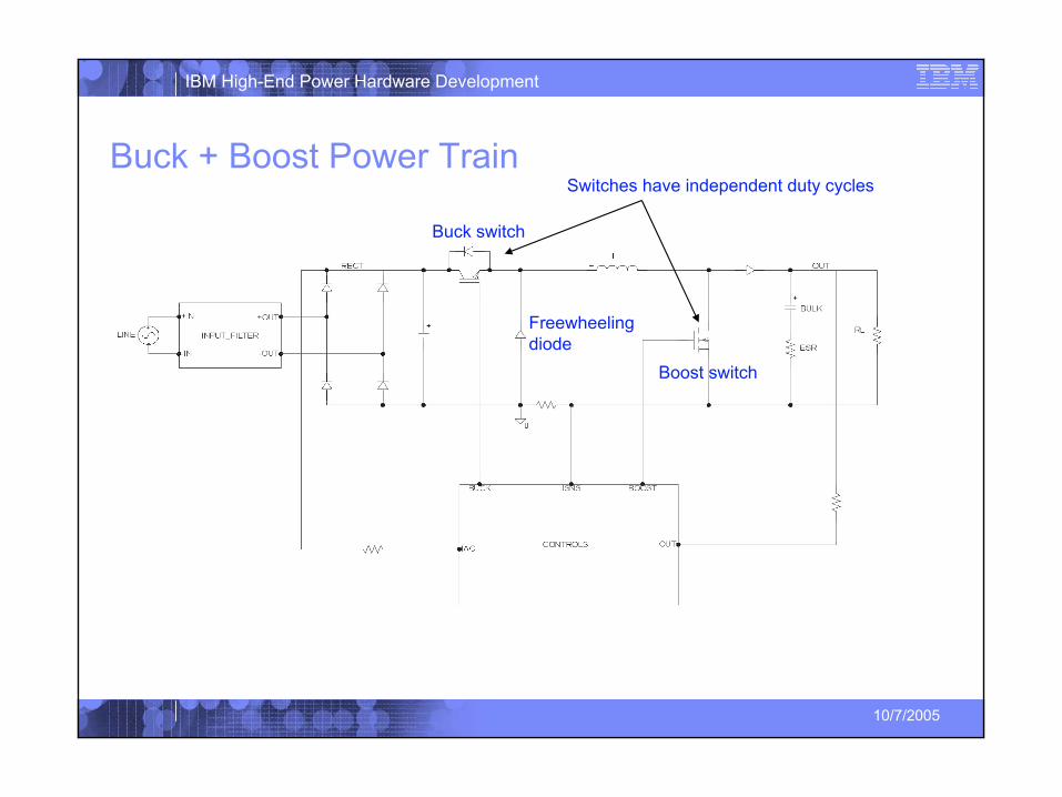
Buck + Boost Power Train
Buck switch
Freewheeling diode
Switches have independent duty cycles
Boost switch
4
IBM High-End Power Hardware Development
10/7/2005
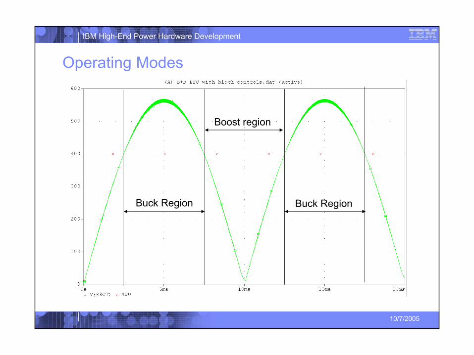
Operating Modes
Boost region
Buck Region Buck Region
5
IBM High-End Power Hardware Development
10/7/2005
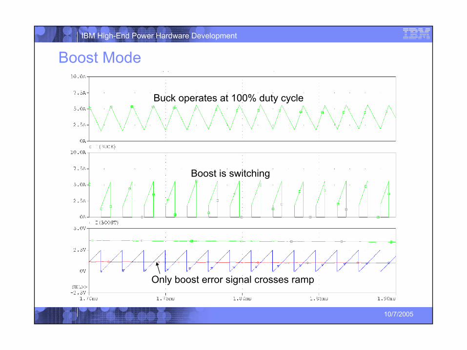
Boost Mode
Boost is switching
Buck operates at 100% duty cycle
Only boost error signal crosses ramp
6
IBM High-End Power Hardware Development
10/7/2005
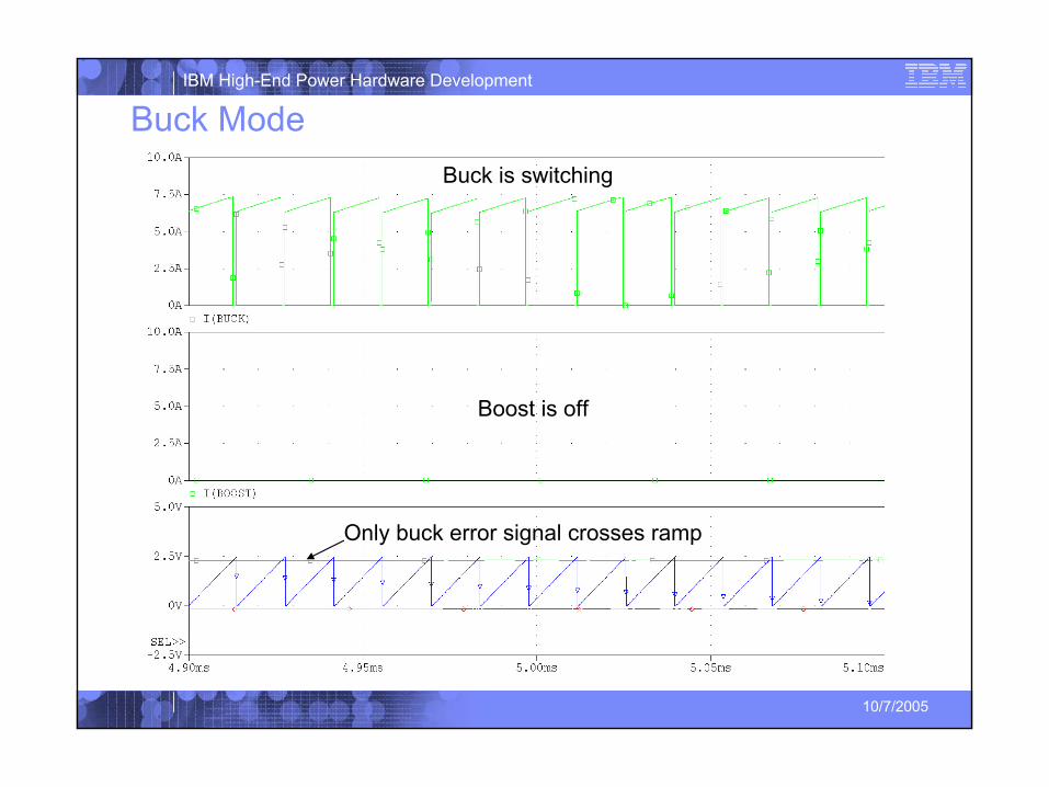
Buck ModeBuck is switching
Boost is off
Only buck error signal crosses ramp
7
IBM High-End Power Hardware Development
10/7/2005
Why use Buck+Boost for Single-Phase?Buck switch eliminates boost inrush problem
Buck switch functions as prime-power disconnect
Input current can be controlled
Enhanced PLD immunity
8
IBM High-End Power Hardware Development
10/7/2005
Controls: Prior Art
9
IBM High-End Power Hardware Development
10/7/2005
Buck+Boost ControlBuck+Boost converter is difficult to control in continuous-conduction mode
Early applications operated the inductor on the verge of discontinuous conduction to maintain stability impractical for high power applications
In 1993 Dr. Ray Ridley developed a controller that maintains stability even in continuous conduction mode
The addition of an inner current loop provides adaptability to changing power stage operation
10
IBM High-End Power Hardware Development
10/7/2005
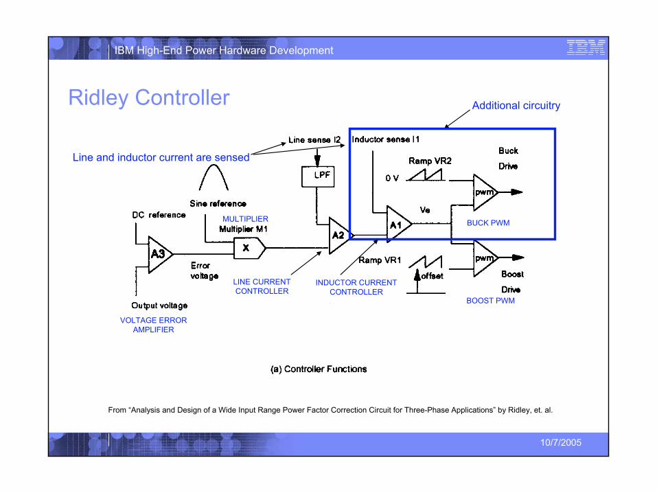
Ridley Controller
From “Analysis and Design of a Wide Input Range Power Factor Correction Circuit for Three-Phase Applications” by Ridley, et. al.
Additional circuitry
LINE CURRENT CONTROLLER
MULTIPLIER
VOLTAGE ERROR AMPLIFIER
BUCK PWM
INDUCTOR CURRENT CONTROLLER
Line and inductor current are sensed
BOOST PWM
11
IBM High-End Power Hardware Development
10/7/2005
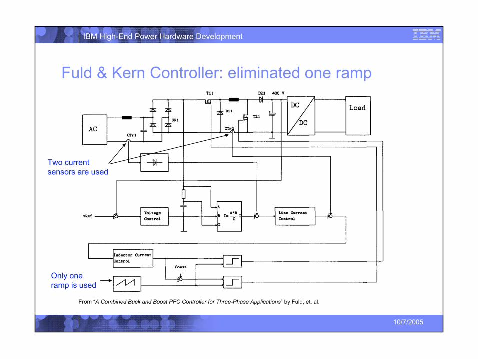
Fuld & Kern Controller: eliminated one ramp
From “A Combined Buck and Boost PFC Controller for Three-Phase Applications” by Fuld, et. al.
Only one ramp is used
Two current sensors are used
12
IBM High-End Power Hardware Development
10/7/2005
Summary of prior art
Both earlier schemes required two sensors for line and inductor current
Efficiency penalty at lower power levels where resistive shunts are used
Cost penalty at high power levels where Hall-effect sensors are used
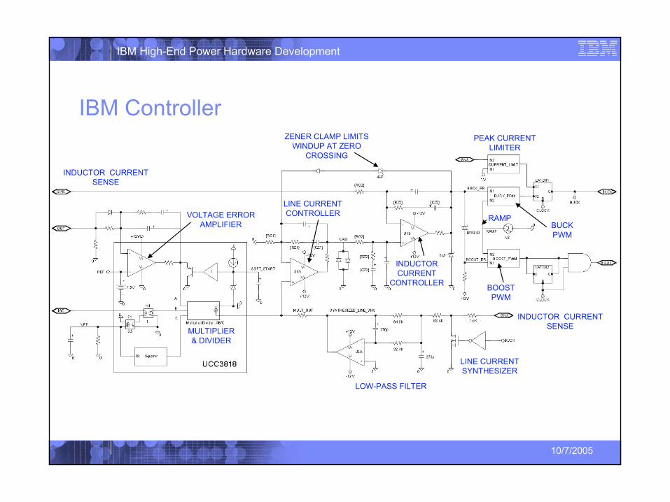
IBM controller requires that only inductor current be sensed
Line current is synthesized by controller
13
IBM High-End Power Hardware Development
10/7/2005
IBM Controller
BUCK PWM
LINE CURRENT CONTROLLER
INDUCTOR CURRENT
CONTROLLER
LINE CURRENT SYNTHESIZER
MULTIPLIER & DIVIDER
VOLTAGE ERROR AMPLIFIER
PEAK CURRENT LIMITER
BOOST PWM
LOW-PASS FILTER
INDUCTOR CURRENT SENSE
INDUCTOR CURRENT SENSE
RAMP
ZENER CLAMP LIMITS WINDUP AT ZERO
CROSSING
14
IBM High-End Power Hardware Development
10/7/2005
Simulated Performance
15
IBM High-End Power Hardware Development
10/7/2005
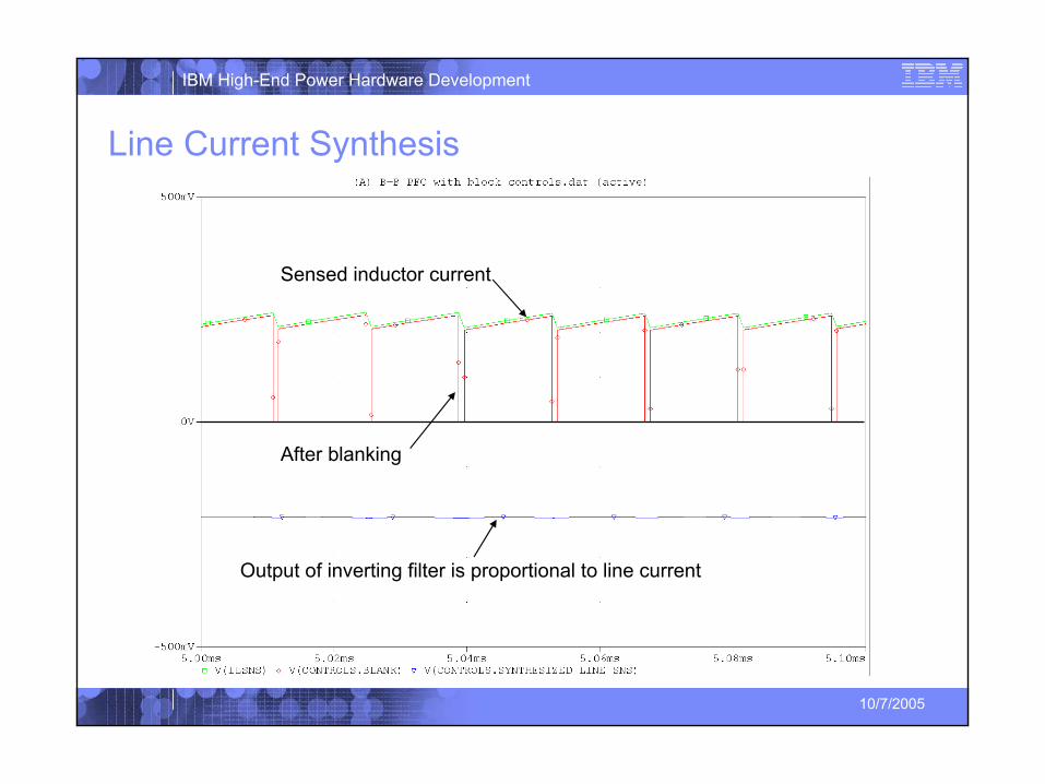
Line Current Synthesis
Sensed inductor current
After blanking
Output of inverting filter is proportional to line current
16
IBM High-End Power Hardware Development
10/7/2005
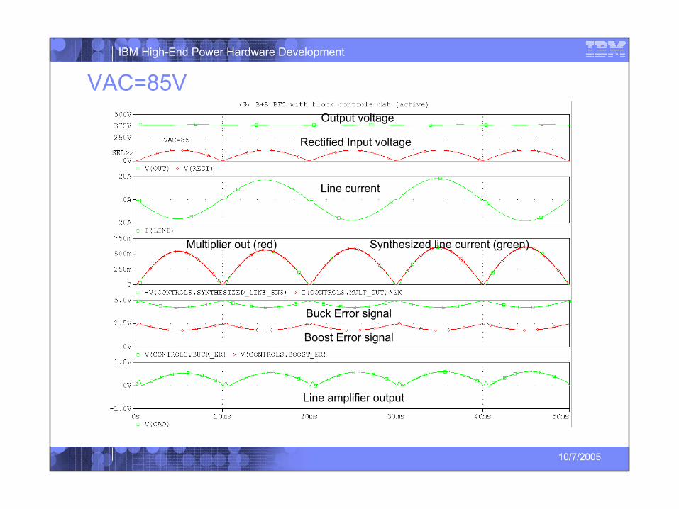
VAC=85V
Line amplifier output
Multiplier out (red) Synthesized line current (green)
Boost Error signal
Line current
Rectified Input voltage
Output voltage
Buck Error signal
17
IBM High-End Power Hardware Development
10/7/2005
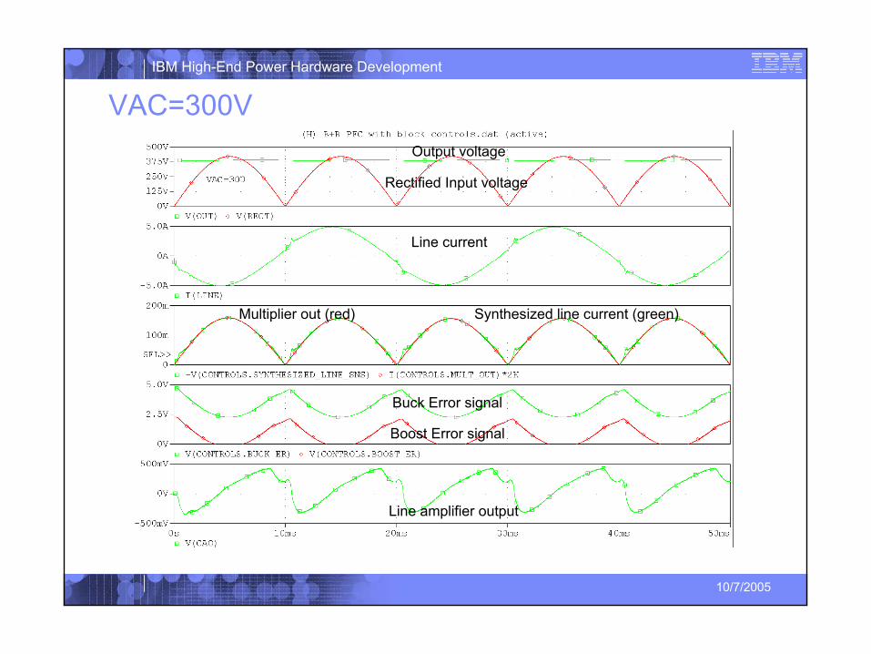
VAC=300V
Line amplifier output
Multiplier out (red) Synthesized line current (green)
Boost Error signal
Line current
Rectified Input voltage
Output voltage
Buck Error signal
18
IBM High-End Power Hardware Development
10/7/2005
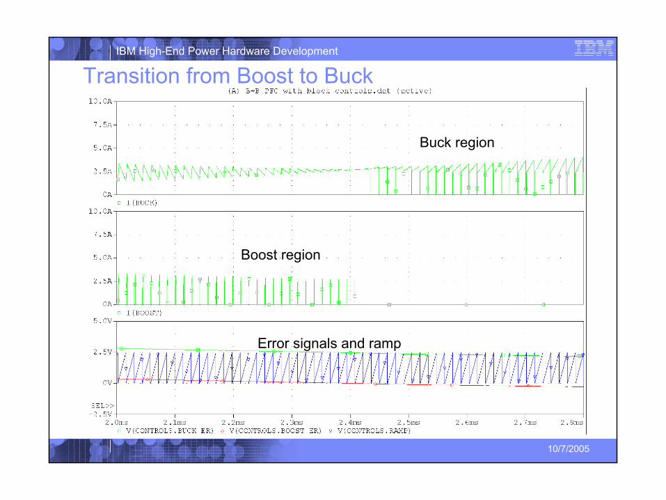
Transition from Boost to Buck
Boost region
Buck region
Error signals and ramp
19
IBM High-End Power Hardware Development
10/7/2005
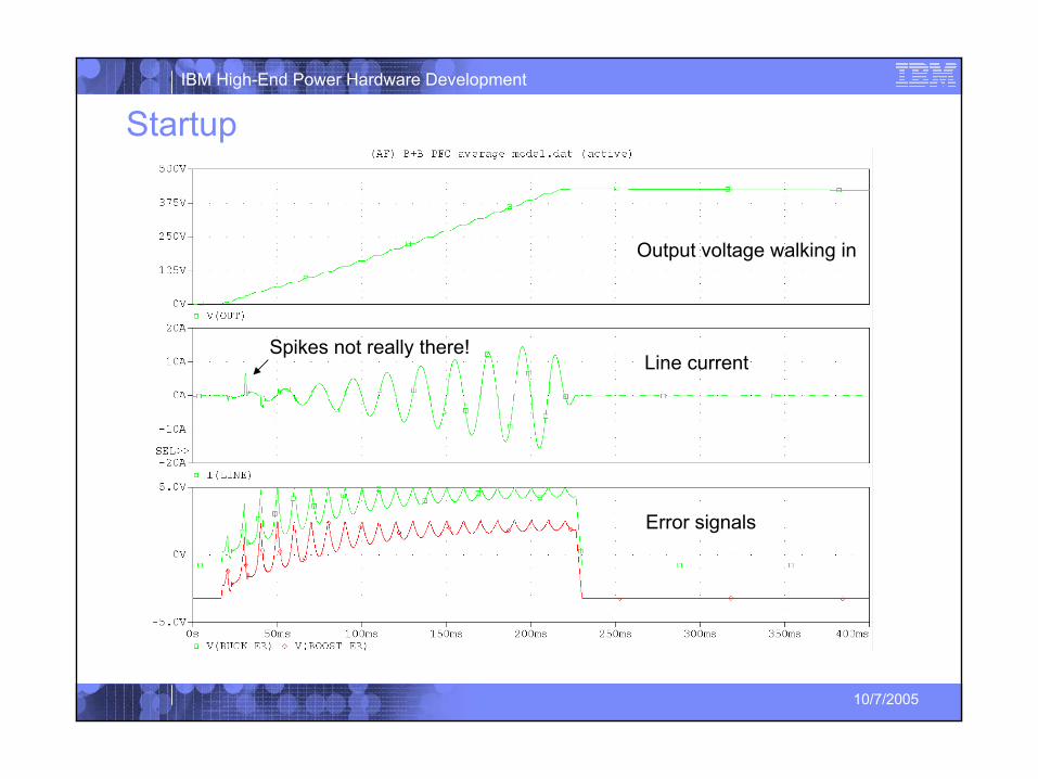
Startup
Spikes not really there!
Output voltage walking in
Error signals
Line current
20
IBM High-End Power Hardware Development
10/7/2005
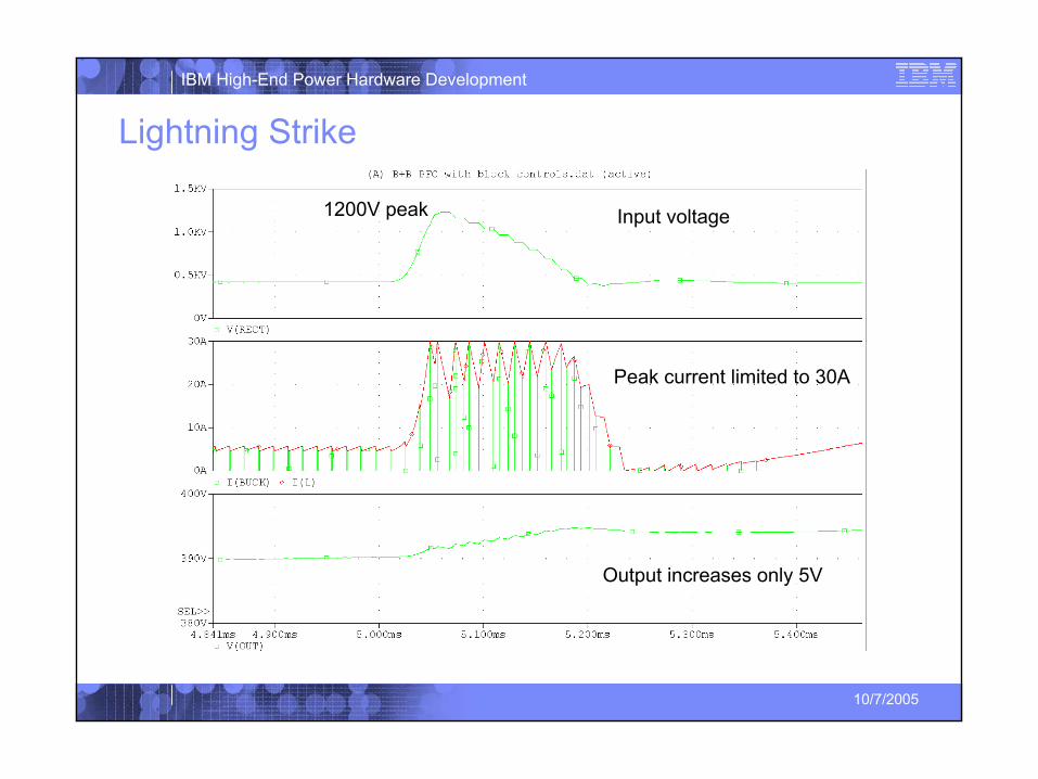
Lightning Strike
Peak current limited to 30A
Output increases only 5V
Input voltage1200V peak
21
IBM High-End Power Hardware Development
10/7/2005
Measured Performance of 7.5kW Rectifier
22
IBM High-End Power Hardware Development
10/7/2005
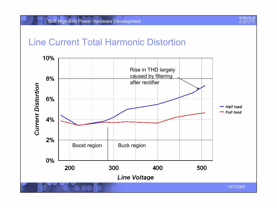
Line Current Total Harmonic Distortion
Rise in THD largely caused by filtering after rectifier
Boost region Buck region
23
IBM High-End Power Hardware Development
10/7/2005
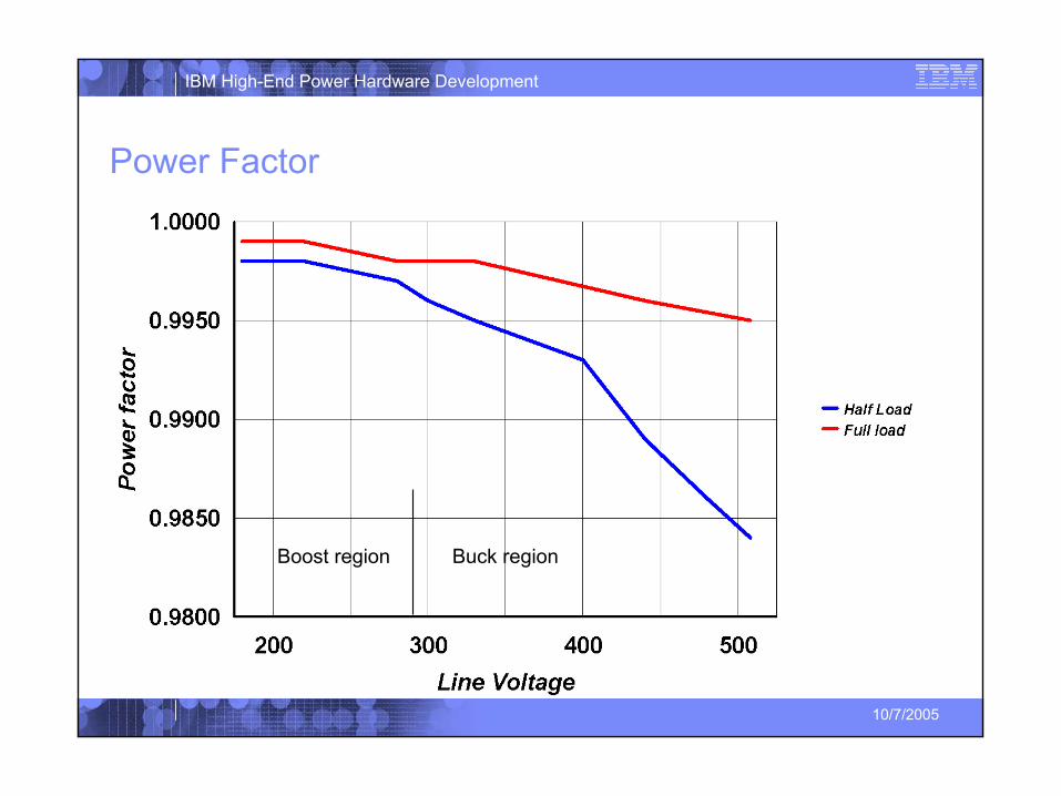
Power Factor
Boost region Buck region
24
IBM High-End Power Hardware Development
10/7/2005
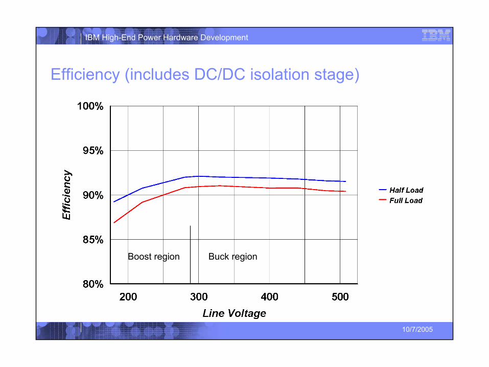
Efficiency (includes DC/DC isolation stage)
Boost region Buck region

25
IBM High-End Power Hardware Development
10/7/2005
Summary
26
IBM High-End Power Hardware Development
10/7/2005
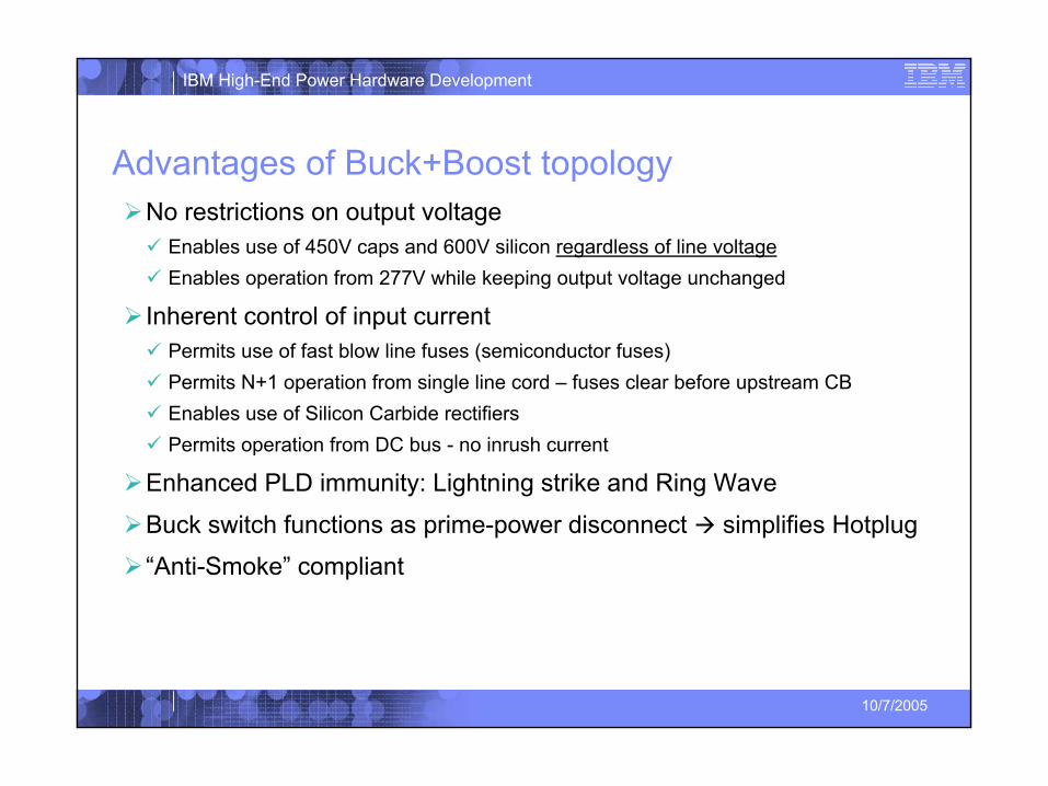
Advantages of Buck+Boost topologyNo restrictions on output voltage
Enables use of 450V caps and 600V silicon regardless of line voltageEnables operation from 277V while keeping output voltage unchanged
Inherent control of input currentPermits use of fast blow line fuses (semiconductor fuses)Permits N+1 operation from single line cord – fuses clear before upstream CBEnables use of Silicon Carbide rectifiersPermits operation from DC bus - no inrush current
Enhanced PLD immunity: Lightning strike and Ring Wave
Buck switch functions as prime-power disconnect simplifies Hotplug
“Anti-Smoke” compliant
27
IBM High-End Power Hardware Development
10/7/2005
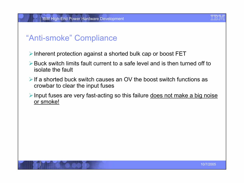
“Anti-smoke” Compliance
Inherent protection against a shorted bulk cap or boost FET
Buck switch limits fault current to a safe level and is then turned off to isolate the fault
If a shorted buck switch causes an OV the boost switch functions as crowbar to clear the input fuses
Input fuses are very fast-acting so this failure does not make a big noise or smoke!
28
IBM High-End Power Hardware Development
10/7/2005
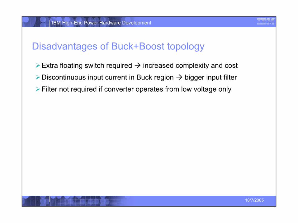
Disadvantages of Buck+Boost topology
Extra floating switch required increased complexity and cost
Discontinuous input current in Buck region bigger input filter
Filter not required if converter operates from low voltage only
29
IBM High-End Power Hardware Development
10/7/2005
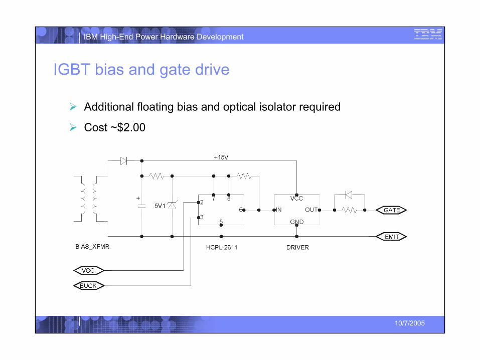
IGBT bias and gate drive
Additional floating bias and optical isolator required
Cost ~$2.00

30
IBM High-End Power Hardware Development
10/7/2005
Optional Input Filter
Filter not required if converter runs in boost mode steady state
Damping
3rd order elliptical
31
IBM High-End Power Hardware Development
10/7/2005
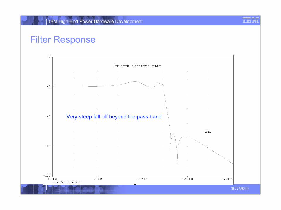
Filter Response
Very steep fall off beyond the pass band
32
IBM High-End Power Hardware Development
10/7/2005
References
33
IBM High-End Power Hardware Development
10/7/2005
References:1. E.G Schmidtner, P.W. Busch, “Off-Line Power Supply with Sinusoidal Input
Current and an Active Limit to the Inrush Current”, Power Conversion (PCIM) Conference Proceedings, Nurnberg, Germany, June 25-27, 1991.
2. R. B. Ridely, S. Kern, B. Fuld, “Analysis and Design of a Wide Input Range Power Factor Correction Circuit for Three-Phase Applications”, Applied Power Electronics Conference and Exposition, 1993. APEC '93. Conference Proceedings 1993., Eighth Annual , 7-11 March 1993
3. B. Fuld, S. Kern, R. B. Ridely, “A Combined Buck and Boost PFC Controller for Three-Phase Applications”, Power Electronics and Applications, 1993, Fifth European Conference on Power Electronics, 13-16 September 1993
4. V. Vlatkovic, D. Borojevic, and F.C. Lee, “Input Filter Design for Power Factor Correction Circuits”, International Conference on Industrial Electronics, Control and Instrumentation, November 1993


![Bridgeless Buck-Boost PFC Converter for Multistring LED Driver€¦ · boost converter as a universal PFC converter [6]. In order to address these issues, a buck-boost converter is](https://img.pdfslide.us/doc/110x75/5eaabf2a4ab79d1e774f9005/bridgeless-buck-boost-pfc-converter-for-multistring-led-driver-boost-converter-as.jpg)