Embed Size (px)
Citation preview
1
A Collaborative Early-Stage Ship Design Environment
Julie Chalfant, Blake Langland, Sherif Abdelwahed, Chryssostomos Chryssostomidis, Roger Dougal, Abhishek Dubey, Touria El Mezyani, John Herbst, Thomas Kiehne, Juan Ordonez, Scott Pish, Sanjeev
Srivastava and Ed Zivi
Abstract— Recent advances in sensor and weapons systems are
significantly increasing the electrical power that is required and the thermal loads that must be dissipated onboard US Navy ships. Thus, design tools and methods must bring detailed consideration of all disciplines early in the design process, including electrical, thermal and controls in addition to the traditional naval architecture and marine engineering. Effective interface of the multiple disciplines demands a collaborative design process.
The Electric Ship Research and Development Consortium (ESRDC) has developed the backbone structure of a collaborative design environment with the goal of bringing together many disciplines early in the ship design process. This design environment brings many innovations, especially in the arena of simultaneous collaborative design.
This paper describes the Smart Ship System Design (S3D) environment as developed to date, along with overall and discipline-specific visions of implementation of the environment in ship design.
Index Terms—Collaborative design software, early-stage ship design, cross-discipline design.
I. INTRODUCTION N recent years, interest has developed in ship designs that depart significantly from past practice. The most recent
surface ships added to the US Navy’s fleet include a high-
Manuscript received May 22, 2012. This work was supported in part by the
Office of Naval Research N00014-08-1-0080, ESRDC Consortium, N00014-09-1-0160, Sea Basing: T-Craft Dynamic Analysis, and MIT Sea Grant College Program, NA10OAR4170086.
J. Chalfant and C. Chryssostomidis are with the Design Laboratory of the MIT Sea Grant Program, Massachusetts Institute of Technology, Cambridge, MA, 02139. Corresponding author: phone: 617-253-9309, [email protected], [email protected].
B. Langland and R. Dougal are with the College of Engineering and Computing at the University of South Carolina, Columbia, SC, 29208, email: [email protected], [email protected].
J. Herbst, T. Kiehne and S. Pish are with the Center for Electromechanics at the University of Texas at Austin, Austin, TX, 78758, [email protected], [email protected], [email protected].
T. El Mezyani, J. Ordonez and S. Srivastava are with the Center for Advanced Power Systems, Florida State University, Tallahassee, FL, 32310, [email protected], [email protected], [email protected].
S. Abdelwahed is with the College of Engineering at Mississippi State University, Mississippi State, MS 39762, [email protected].
A. Dubey is with the School of Engineering at Vanderbilt University, Nashville, TN 37240.
E. Zivi is with the Department of Weapons and Systems Engineering at the United States Naval Academy, Annapolis, MD 20401, [email protected].
speed shallow-water semi-planing vessel (USS FREEDOM (LCS 1)), a trimaran (USS INDEPENDENCE (LCS 2)), a hybrid-drive amphibious assault ship (USS MAKIN ISLAND (LHD-8)), and soon an electric-drive destroyer with a tumblehome hull (USS ZUMWALT (DDG 1000)). The complexity of these vessels is increasing in every arena including weapons and sensor systems, ship control systems, power electronics, propulsion machinery, and hull and propulsor configurations. It is envisioned that continuing advances especially in power-intensive sensor and weapons systems will precipitate even greater changes in the traditional ship support-system design, making it imperative that the electrical and thermal system designs play a greater role very early in the design process.
Through many years of research, the Electric Ship Research and Development Consortium, ESRDC, has developed methods and tools for analyzing shipboard systems in single domains, often wrapped in simulation methods and executable simulators. In addition, several simulators that cross the disciplinary boundaries have been developed, and methods have been developed for optimizing concept designs according to some cost functions; however, these tools generally operate only within the domain of a single person’s expertise.
The development of innovative, cost effective, and superior ship designs in a timely manner requires new tools that enable rapid collaboration across the entire scope of involved disciplines and human resources. No system is independent of any other, and no individual can know all the nuances of the entire system. Subsystem optimization must be accomplished with consideration of the operation of the entire ship.
In response to this need, ESRDC is in the process of developing, demonstrating, and testing the structure and efficacy of a collaborative environment that converges ship system designs at an early stage. The design environment accounts for input from all the major hull, mechanical, and electrical disciplines, including but not limited to naval architecture, electric power, mechanical power, thermal management, and control systems.
This paper provides a description of the collaborative tool as developed to date, including the underlying structure and the roles and interactions of disciplines. The paper is organized as follows. The remainder of this section provides additional background information. Section II describes the current design tool. Section III explores the use of the S3D tool for a new concept design. Section IV discusses each
I

2
discipline in more detail, providing a discussion of the types of analyses and procedures inherent in the design process. Section V describes the CONTEST methodology which can be used to compare alternatives. The paper concludes with recommendations for future work and the vision of the tool to be developed over the next one to two years.
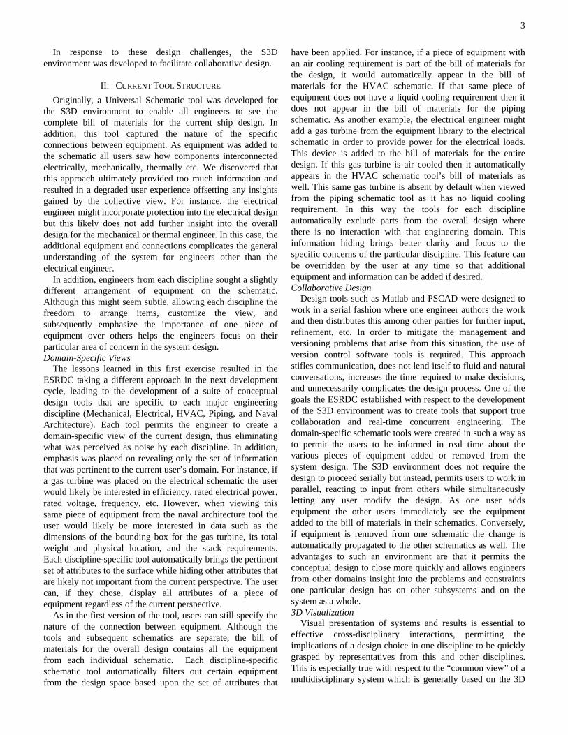
A. Ship Design Background Early-stage ship design is traditionally described as a design
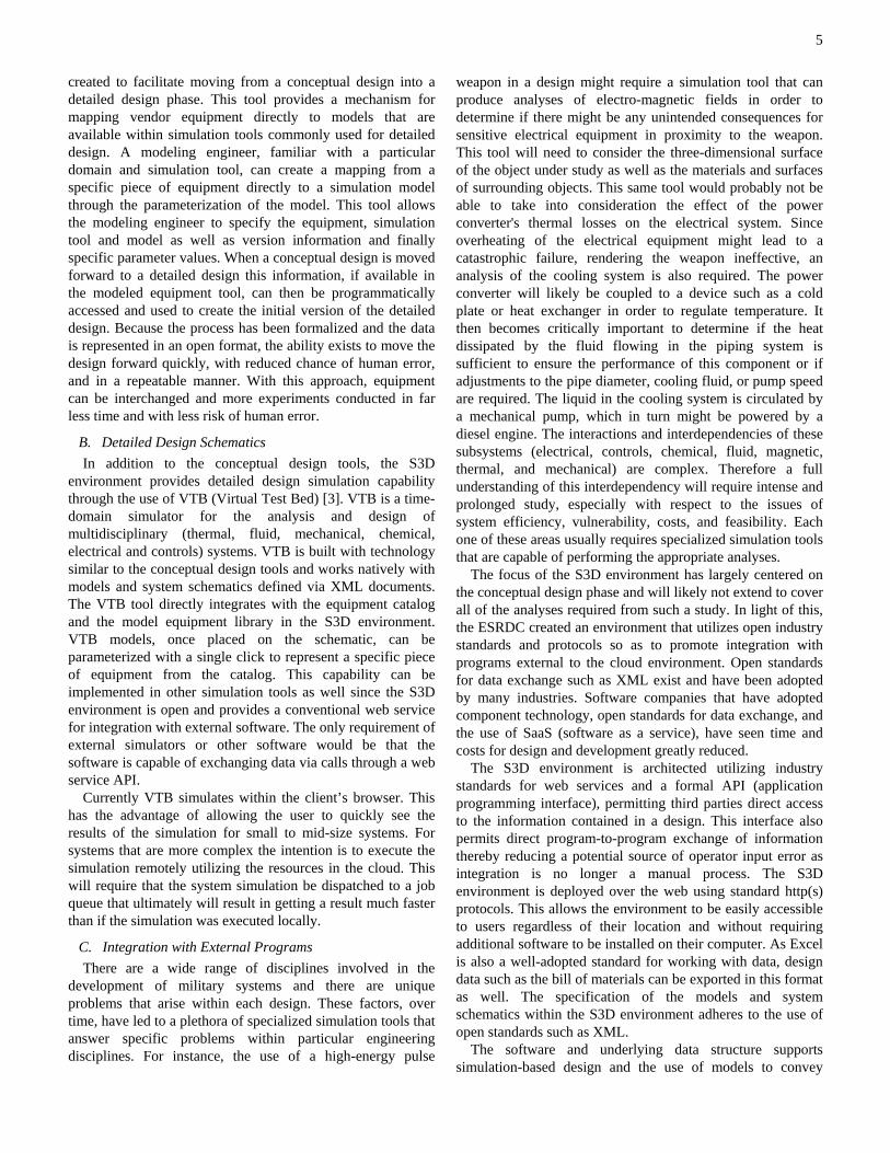
spiral, in which design events are sequentially addressed in order to achieve a converged, feasible ship design. Successive passes of the spiral are conducted to achieve ever-increasing detail in the ship design. An example of this spiral can be seen in Figure 1.
Figure 1: Design spiral [1]
Mistree et al. [2] point out two problems with viewing ship design as a spiral. First, the spiral concept imposes a linear approach to ship design, whereas in actuality each of the stages has interactions with the others. Second, the spiral approach does not facilitate overall optimization for such concerns as life-cycle cost, modularity, or integrated operations.
A third problem is introduced by the increasing complexity of Navy warship weapons and sensors, which require more complex and integrated control, propulsion and support systems. It is becoming evident that the integration of expertise from multiple disciplines at early stages of design could produce a more viable design, provided that the various inputs can be managed in an effective manner.
A number of early-stage ship design tools currently exist and are used in various venues; two are described here. The Advanced Surface Ship Evaluation Tool (ASSET) is used by the U.S. Navy to explore concepts in early-stage design. ASSET is a powerful tool which an expert user can use to fairly rapidly generate and analyze multiple early-stage ship designs; however, this tool is based on paramtrics derived from previous designs and therefore is not well suited for exploration of new-concept designs that differ significantly from past practice. In addition, each change results in a newly synthesized ship, so it becomes difficult to discern the effects of a single change. Paramarine is a tool used by the British Ministry of Defense and available commercially. This very
capable tool has many built-in naval architecture analyses and again, an expert user can successfully generate early-stage ship designs using the software. The strength of Paramarine is also a drawback: its extreme flexibility requires significant effort to create new ship designs. It is also somewhat better able to handle new concepts since it is not as parametrically based. The user sets up all interrelationships, so the effects of changes are more evident than seen in ASSET.
These tools along with others such as Rhino Orca3D and MaxSurf address to some degree the traditional naval architecture concerns including intact stability, damaged stability, structural strength, resistance, propulsion, and seakeeping. They do not generally accomplish designs of sub-systems, such as the more extensive electrical system modeling that is becoming necessary for early-stage design of electric-drive vessels.
To be truly useful throughout the naval ship design community, the design methodology for early-stage ship design in S3D needs to capture the major steps in the current design spiral; however, the new design activities must be adapted and organized to optimize the overall process in the new design environment.
B. Collaborative Design Over the last several decades the complexity and
sophistication of military systems have dramatically increased, now requiring many specialized design and engineering teams spanning multiple domains. The need for modeling and simulation tools to complete the design of a system, provide an understanding of the interdependencies between subsystems, and make manifest problems that may not have been initially anticipated, becomes obvious when one looks at the sheer scale of the design process. Identifying interdependencies, their associated problems or risks as early as possible in the design process is paramount to effective cost and time management as well as a better optimized overall design.
As the complexity of the design increases, so does the number of simulation tools required to produce and analyze the trade-off studies between competing designs. The likelihood that these tools and the users of these tools will be able to exchange data in a timely and meaningful way is substantially diminished with the addition of each tool. Traditional design processes suffer from communication barriers that naturally exist between simulation tools and users which ultimately add significant costs and time to the design cycle. Furthermore, they are a potential source of operator input error as the integration necessarily becomes more of a manual process. If, for example, three dimensional data for an electromagnetic analysis needs to be input into a simulation tool in one format, but then must be manually converted and entered into another tool that performs stress analysis, significant cost and time will be added to the design cycle as well as an avenue for introducing error. If there are a large number of scenarios that must be run in order to perform a thorough trade-off study, then the cost would be multiplied accordingly.
3
In response to these design challenges, the S3D environment was developed to facilitate collaborative design.
II. CURRENT TOOL STRUCTURE Originally, a Universal Schematic tool was developed for
the S3D environment to enable all engineers to see the complete bill of materials for the current ship design. In addition, this tool captured the nature of the specific connections between equipment. As equipment was added to the schematic all users saw how components interconnected electrically, mechanically, thermally etc. We discovered that this approach ultimately provided too much information and resulted in a degraded user experience offsetting any insights gained by the collective view. For instance, the electrical engineer might incorporate protection into the electrical design but this likely does not add further insight into the overall design for the mechanical or thermal engineer. In this case, the additional equipment and connections complicates the general understanding of the system for engineers other than the electrical engineer.
In addition, engineers from each discipline sought a slightly different arrangement of equipment on the schematic. Although this might seem subtle, allowing each discipline the freedom to arrange items, customize the view, and subsequently emphasize the importance of one piece of equipment over others helps the engineers focus on their particular area of concern in the system design. Domain-Specific Views
The lessons learned in this first exercise resulted in the ESRDC taking a different approach in the next development cycle, leading to the development of a suite of conceptual design tools that are specific to each major engineering discipline (Mechanical, Electrical, HVAC, Piping, and Naval Architecture). Each tool permits the engineer to create a domain-specific view of the current design, thus eliminating what was perceived as noise by each discipline. In addition, emphasis was placed on revealing only the set of information that was pertinent to the current user’s domain. For instance, if a gas turbine was placed on the electrical schematic the user would likely be interested in efficiency, rated electrical power, rated voltage, frequency, etc. However, when viewing this same piece of equipment from the naval architecture tool the user would likely be more interested in data such as the dimensions of the bounding box for the gas turbine, its total weight and physical location, and the stack requirements. Each discipline-specific tool automatically brings the pertinent set of attributes to the surface while hiding other attributes that are likely not important from the current perspective. The user can, if they chose, display all attributes of a piece of equipment regardless of the current perspective.
As in the first version of the tool, users can still specify the nature of the connection between equipment. Although the tools and subsequent schematics are separate, the bill of materials for the overall design contains all the equipment from each individual schematic. Each discipline-specific schematic tool automatically filters out certain equipment from the design space based upon the set of attributes that
have been applied. For instance, if a piece of equipment with an air cooling requirement is part of the bill of materials for the design, it would automatically appear in the bill of materials for the HVAC schematic. If that same piece of equipment does not have a liquid cooling requirement then it does not appear in the bill of materials for the piping schematic. As another example, the electrical engineer might add a gas turbine from the equipment library to the electrical schematic in order to provide power for the electrical loads. This device is added to the bill of materials for the entire design. If this gas turbine is air cooled then it automatically appears in the HVAC schematic tool’s bill of materials as well. This same gas turbine is absent by default when viewed from the piping schematic tool as it has no liquid cooling requirement. In this way the tools for each discipline automatically exclude parts from the overall design where there is no interaction with that engineering domain. This information hiding brings better clarity and focus to the specific concerns of the particular discipline. This feature can be overridden by the user at any time so that additional equipment and information can be added if desired. Collaborative Design
Design tools such as Matlab and PSCAD were designed to work in a serial fashion where one engineer authors the work and then distributes this among other parties for further input, refinement, etc. In order to mitigate the management and versioning problems that arise from this situation, the use of version control software tools is required. This approach stifles communication, does not lend itself to fluid and natural conversations, increases the time required to make decisions, and unnecessarily complicates the design process. One of the goals the ESRDC established with respect to the development of the S3D environment was to create tools that support true collaboration and real-time concurrent engineering. The domain-specific schematic tools were created in such a way as to permit the users to be informed in real time about the various pieces of equipment added or removed from the system design. The S3D environment does not require the design to proceed serially but instead, permits users to work in parallel, reacting to input from others while simultaneously letting any user modify the design. As one user adds equipment the other users immediately see the equipment added to the bill of materials in their schematics. Conversely, if equipment is removed from one schematic the change is automatically propagated to the other schematics as well. The advantages to such an environment are that it permits the conceptual design to close more quickly and allows engineers from other domains insight into the problems and constraints one particular design has on other subsystems and on the system as a whole. 3D Visualization
Visual presentation of systems and results is essential to effective cross-disciplinary interactions, permitting the implications of a design choice in one discipline to be quickly grasped by representatives from this and other disciplines. This is especially true with respect to the “common view” of a multidisciplinary system which is generally based on the 3D
4
physical view. Three-dimensional CAD tools are useful in verifying the fit of critical components early in the ship design process. The information learned and the CAD models created from these early exercises need to be shared with the larger design team. This process is often hindered due to the distributed nature of design activities that arises within larger groups of engineering teams and due to the adoption of multiple 3D CAD tools. The wide range of CAD tools requires robust information exchange mechanisms and possibly the development of tools that can facilitate the conversion to and from the various data formats.
Simulation models and 3D CAD models represent real-world objects in completely different ways. In general, the design being created in the virtual environment should help us better understand certain aspects of the complex system and to predict its performance while operating under various scenarios. The mechanical, electrical, piping and HVAC schematic design tools are necessary in order to capture the logical design of a system. However, these tools by themselves are insufficient as they lack the ability to specify the physical arrangement of the various parts. A 3D visualization tool was deemed a necessary part of the collaborative environment; helping all participants to establish a more complete understanding of the system being designed. In addition, a 3D visualization tool provides another mechanism for the users to quickly identify design problems early by providing a realistic representation of the system being developed. The 3D environment is likely the most appropriate way to assist the decision makers and stakeholders in better understanding the consequences of alternative designs and leading the entire team to a more credible design.
In order to create a more complete design environment, the ESRDC created a naval architecture tool with a 3D schematic as the primary method for capturing the physical arrangement of the equipment comprising the design. This tool is similar to the logical 2D schematic tools except that there is no automatic filter feature. All equipment that has been added to the bill of materials is displayed by default. The user can choose to hide equipment if so desired. The other major difference is that the naval architect works with true 3D models of the equipment and places these in 3D space.
The ESRDC investigated the various CAD formats available for representing 3D models. There are several formats that could be utilized and most mainstream CAD tools are capable of importing and exporting models into several of these industry-standard formats. Initially the STEP file format was investigated as it permits information beyond the 3D geometry to be captured. Although this seemed appealing in that metadata could be embedded along with the 3D geometry, ultimately this would require other tools to have to have knowledge of a proprietary file format in order to extract non-geometric information about the equipment.
In order to increase interoperability and information exchange a database was created in which the design and equipment attributes can be fully captured. Databases are extremely powerful in this regard as they allow the structure of the data to be formalized and permit the storing and
retrieving of information in an application-neutral form. Databases provide standard interfaces for querying and have built-in transaction capability which helps promote collaboration between multiple parties in real time. The 3D CAD files representing a piece of equipment are uploaded to the S3D environment and can be used for visualization purposes within the environment as well as being available for download and use by external tools.
A. Equipment Catalog and Modeled Equipment Tools The advantages that modeling and simulation offer help to
reduce the costs and time of development. At the same time they allow for increased quality and efficiency. There are an abundance of mature cutting-edge tools that have reached a level of sophistication that enables users to penetrate deep into the design of a system within any particular domain. However, there are significant gaps that have not been addressed by industry thus far and that negatively impact the military’s ability to react to emergent threats in a timely manner, and further, limit the military’s ability to re-factor existing designs without making substantial or additional financial commitments to the design effort. In particular, as the development of novel and complex designs for military systems progresses from conceptual to detailed design, the level of detail required to be coded into simulation models necessarily increases. The underlying costs and time associated with these modeling activities can be substantial.
The ESRDC has created an infrastructure and developed initial versions of tools within the S3D environment to address some of these problems. The equipment catalog tool was created to house the manufacturer’s data for various equipment needed onboard surface combatants. The equipment catalog permits vendors to upload product data, specify equipment attributes such as the physical dimensions, voltage ratings, power ratings, as well as upload any ancillary documents such as specification sheets, CAD files, etc. Once this data has been uploaded this information is made generally available to the design engineers. The equipment in the catalog can be searched, sorted, and filtered in order to find off-the-shelf solutions to problems presented by the current design. The data in the equipment catalog can also be mined to extract characteristic plots as well as discover gaps in the capabilities of devices. This information can then be used to help focus research efforts. As this high-level data for the equipment is captured within the catalog, it can be consumed directly by basic power flow models allowing a crude approximation of the equipment to be represented as the equipment is placed on a schematic. These models, although not sophisticated, give basic insight into a design; they help to eliminate designs which are not close to convergence, build confidence levels, and help to identify areas of risk where further investigation is required.
At some point the project transitions from a conceptual phase to a detailed design phase. Much time can be spent extracting topological information, equipment, parameter settings, etc., from one tool and propagating this to a tool capable of deeper analysis. The modeled equipment tool was
5
created to facilitate moving from a conceptual design into a detailed design phase. This tool provides a mechanism for mapping vendor equipment directly to models that are available within simulation tools commonly used for detailed design. A modeling engineer, familiar with a particular domain and simulation tool, can create a mapping from a specific piece of equipment directly to a simulation model through the parameterization of the model. This tool allows the modeling engineer to specify the equipment, simulation tool and model as well as version information and finally specific parameter values. When a conceptual design is moved forward to a detailed design this information, if available in the modeled equipment tool, can then be programmatically accessed and used to create the initial version of the detailed design. Because the process has been formalized and the data is represented in an open format, the ability exists to move the design forward quickly, with reduced chance of human error, and in a repeatable manner. With this approach, equipment can be interchanged and more experiments conducted in far less time and with less risk of human error.
B. Detailed Design Schematics In addition to the conceptual design tools, the S3D
environment provides detailed design simulation capability through the use of VTB (Virtual Test Bed) [3]. VTB is a time-domain simulator for the analysis and design of multidisciplinary (thermal, fluid, mechanical, chemical, electrical and controls) systems. VTB is built with technology similar to the conceptual design tools and works natively with models and system schematics defined via XML documents. The VTB tool directly integrates with the equipment catalog and the model equipment library in the S3D environment. VTB models, once placed on the schematic, can be parameterized with a single click to represent a specific piece of equipment from the catalog. This capability can be implemented in other simulation tools as well since the S3D environment is open and provides a conventional web service for integration with external software. The only requirement of external simulators or other software would be that the software is capable of exchanging data via calls through a web service API.
Currently VTB simulates within the client’s browser. This has the advantage of allowing the user to quickly see the results of the simulation for small to mid-size systems. For systems that are more complex the intention is to execute the simulation remotely utilizing the resources in the cloud. This will require that the system simulation be dispatched to a job queue that ultimately will result in getting a result much faster than if the simulation was executed locally.
C. Integration with External Programs There are a wide range of disciplines involved in the
development of military systems and there are unique problems that arise within each design. These factors, over time, have led to a plethora of specialized simulation tools that answer specific problems within particular engineering disciplines. For instance, the use of a high-energy pulse
weapon in a design might require a simulation tool that can produce analyses of electro-magnetic fields in order to determine if there might be any unintended consequences for sensitive electrical equipment in proximity to the weapon. This tool will need to consider the three-dimensional surface of the object under study as well as the materials and surfaces of surrounding objects. This same tool would probably not be able to take into consideration the effect of the power converter's thermal losses on the electrical system. Since overheating of the electrical equipment might lead to a catastrophic failure, rendering the weapon ineffective, an analysis of the cooling system is also required. The power converter will likely be coupled to a device such as a cold plate or heat exchanger in order to regulate temperature. It then becomes critically important to determine if the heat dissipated by the fluid flowing in the piping system is sufficient to ensure the performance of this component or if adjustments to the pipe diameter, cooling fluid, or pump speed are required. The liquid in the cooling system is circulated by a mechanical pump, which in turn might be powered by a diesel engine. The interactions and interdependencies of these subsystems (electrical, controls, chemical, fluid, magnetic, thermal, and mechanical) are complex. Therefore a full understanding of this interdependency will require intense and prolonged study, especially with respect to the issues of system efficiency, vulnerability, costs, and feasibility. Each one of these areas usually requires specialized simulation tools that are capable of performing the appropriate analyses.
The focus of the S3D environment has largely centered on the conceptual design phase and will likely not extend to cover all of the analyses required from such a study. In light of this, the ESRDC created an environment that utilizes open industry standards and protocols so as to promote integration with programs external to the cloud environment. Open standards for data exchange such as XML exist and have been adopted by many industries. Software companies that have adopted component technology, open standards for data exchange, and the use of SaaS (software as a service), have seen time and costs for design and development greatly reduced.
The S3D environment is architected utilizing industry standards for web services and a formal API (application programming interface), permitting third parties direct access to the information contained in a design. This interface also permits direct program-to-program exchange of information thereby reducing a potential source of operator input error as integration is no longer a manual process. The S3D environment is deployed over the web using standard http(s) protocols. This allows the environment to be easily accessible to users regardless of their location and without requiring additional software to be installed on their computer. As Excel is also a well-adopted standard for working with data, design data such as the bill of materials can be exported in this format as well. The specification of the models and system schematics within the S3D environment adheres to the use of open standards such as XML.
The software and underlying data structure supports simulation-based design and the use of models to convey
6
specifications of system requirements. This is accomplished through the parameterization of models, and the assignment of attributes to models. Parameterization covers the representation and behavior of the model during the simulation process. The assignment of attributes to a model enhances the understanding of a particular model in a schematic by the operator through incorporation of product specifics, e.g. weight, dimensions, cost, model numbers. These features and the use of industry standards facilitate integration with external tools.
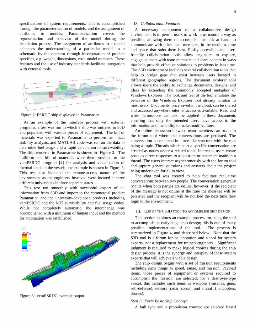
Figure 2: ESRDC ship displayed in Paramarine
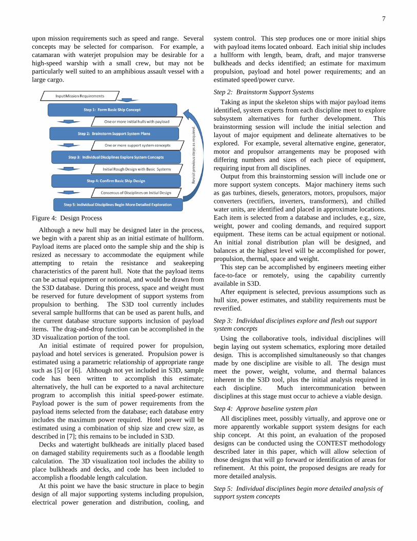
As an example of the interface process with external programs, a test was run in which a ship was initiated in S3D and populated with various pieces of equipment. The bill of materials was exported to Paramarine to perform an intact stability analysis, and MATLAB code was run on the data to determine fuel usage and a rapid calculation of survivability. The ship rendered in Paramarine is shown in Figure 2. The hullform and bill of materials were then provided to the vemESRDC program [4] for analysis and visualization of thermal loads in the vessel; one example is shown in Figure 3. This test also included the remote-access nature of the environment as the engineers involved were located at three different universities in three separate states.
This test ran smoothly with successful export of all information from S3D and import to the commercial product Paramarine and the university-developed products including vemESRDC and the MIT survivability and fuel usage codes. While not completely automatic, the interchange was accomplished with a minimum of human input and the method for automation was established.
Figure 3: vemESRDC example output
D. Collaboration Features A necessary component of a collaborative design
environment is to permit users to work in as natural a way as possible, allowing them to accomplish the task at hand: to communicate with other team members, in the medium, time and space that suits them best. Easily accessible and user-friendly collaboration tools allow engineers to explore, engage, connect with team members and share content in ways that help provide effective solutions to problems in less time. The S3D environment includes several collaboration tools that help to bridge gaps that exist between users located in different geographic regions. The document explorer tool allows users the ability to exchange documents, designs, and ideas by extending the commonly accepted metaphor of Windows Explorer. The look and feel of the tool emulates the behavior of the Windows Explorer tool already familiar to most users. Documents, once saved in the cloud, can be shared and accessed anywhere internet access is available. Read and write permissions can also be applied to these documents ensuring that only the intended users have access to the information and the ability to make modifications.
An online discussion between team members can occur in the forum tool where the conversations are persisted. The conversation is contained in a tree-like structure with the root being a topic. Threads which start a specific conversation are created as nodes under a related topic. Interested users create posts as direct responses to a question or statement made in a thread. The users interact asynchronously with the forum tool and capture general questions and answers about the project being undertaken for all to view.
The chat tool was created to help facilitate real time conversations between two people. The conversation generally occurs when both parties are online, however, if the recipient of the message is not online at the time the message will be persisted and the recipient will be notified the next time they login to the environment.
III. USE OF THE S3D TOOL TO ACCOMPLISH SHIP DESIGN This section explores an example process for using the tool
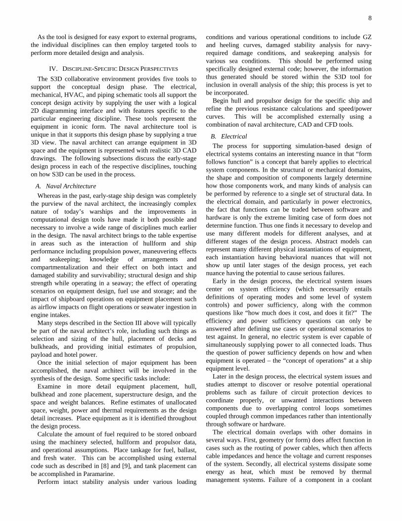
to accomplish an early-stage ship design; this is one of many possible implementations of the tool. The process is summarized in Figure 4, and described below. Note that the S3D tool is a forum for collaboration and a tool for system experts, not a replacement for trained engineers. Significant judgment is required to make logical choices during the ship design process; it is the synergy and interplay of these system experts that will achieve a viable design.
The ship design begins with a set of mission requirements including such things as speed, range, and mission. Payload items, those pieces of equipment or systems required to accomplish the mission, are selected; for a destroyer-type vessel, this includes such items as weapons (missiles, guns, self-defense), sensors (radar, sonar), and aircraft (helicopters, drones).
Step 1: Form Basic Ship Concept A hull type and a propulsion concept are selected based
7
upon mission requirements such as speed and range. Several concepts may be selected for comparison. For example, a catamaran with waterjet propulsion may be desirable for a high-speed warship with a small crew, but may not be particularly well suited to an amphibious assault vessel with a large cargo.
Figure 4: Design Process
Although a new hull may be designed later in the process, we begin with a parent ship as an initial estimate of hullform. Payload items are placed onto the sample ship and the ship is resized as necessary to accommodate the equipment while attempting to retain the resistance and seakeeping characteristics of the parent hull. Note that the payload items can be actual equipment or notional, and would be drawn from the S3D database. During this process, space and weight must be reserved for future development of support systems from propulsion to berthing. The S3D tool currently includes several sample hullforms that can be used as parent hulls, and the current database structure supports inclusion of payload items. The drag-and-drop function can be accomplished in the 3D visualization portion of the tool.
An initial estimate of required power for propulsion, payload and hotel services is generated. Propulsion power is estimated using a parametric relationship of appropriate range such as [5] or [6]. Although not yet included in S3D, sample code has been written to accomplish this estimate; alternatively, the hull can be exported to a naval architecture program to accomplish this initial speed-power estimate. Payload power is the sum of power requirements from the payload items selected from the database; each database entry includes the maximum power required. Hotel power will be estimated using a combination of ship size and crew size, as described in [7]; this remains to be included in S3D.
Decks and watertight bulkheads are initially placed based on damaged stability requirements such as a floodable length calculation. The 3D visualization tool includes the ability to place bulkheads and decks, and code has been included to accomplish a floodable length calculation.
At this point we have the basic structure in place to begin design of all major supporting systems including propulsion, electrical power generation and distribution, cooling, and
system control. This step produces one or more initial ships with payload items located onboard. Each initial ship includes a hullform with length, beam, draft, and major transverse bulkheads and decks identified; an estimate for maximum propulsion, payload and hotel power requirements; and an estimated speed/power curve.
Step 2: Brainstorm Support Systems Taking as input the skeleton ships with major payload items
identified, system experts from each discipline meet to explore subsystem alternatives for further development. This brainstorming session will include the initial selection and layout of major equipment and delineate alternatives to be explored. For example, several alternative engine, generator, motor and propulsor arrangements may be proposed with differing numbers and sizes of each piece of equipment, requiring input from all disciplines.
Output from this brainstorming session will include one or more support system concepts. Major machinery items such as gas turbines, diesels, generators, motors, propulsors, major converters (rectifiers, inverters, transformers), and chilled water units, are identified and placed in approximate locations. Each item is selected from a database and includes, e.g., size, weight, power and cooling demands, and required support equipment. These items can be actual equipment or notional. An initial zonal distribution plan will be designed, and balances at the highest level will be accomplished for power, propulsion, thermal, space and weight.
This step can be accomplished by engineers meeting either face-to-face or remotely, using the capability currently available in S3D.
After equipment is selected, previous assumptions such as hull size, power estimates, and stability requirements must be reverified.
Step 3: Individual disciplines explore and flesh out support system concepts
Using the collaborative tools, individual disciplines will begin laying out system schematics, exploring more detailed design. This is accomplished simultaneously so that changes made by one discipline are visible to all. The design must meet the power, weight, volume, and thermal balances inherent in the S3D tool, plus the initial analysis required in each discipline. Much intercommunication between disciplines at this stage must occur to achieve a viable design.
Step 4: Approve baseline system plan All disciplines meet, possibly virtually, and approve one or
more apparently workable support system designs for each ship concept. At this point, an evaluation of the proposed designs can be conducted using the CONTEST methodology described later in this paper, which will allow selection of those designs that will go forward or identification of areas for refinement. At this point, the proposed designs are ready for more detailed analysis.
Step 5: Individual disciplines begin more detailed analysis of support system concepts
8
As the tool is designed for easy export to external programs, the individual disciplines can then employ targeted tools to perform more detailed design and analysis.
IV. DISCIPLINE-SPECIFIC DESIGN PERSPECTIVES The S3D collaborative environment provides five tools to
support the conceptual design phase. The electrical, mechanical, HVAC, and piping schematic tools all support the concept design activity by supplying the user with a logical 2D diagramming interface and with features specific to the particular engineering discipline. These tools represent the equipment in iconic form. The naval architecture tool is unique in that it supports this design phase by supplying a true 3D view. The naval architect can arrange equipment in 3D space and the equipment is represented with realistic 3D CAD drawings. The following subsections discuss the early-stage design process in each of the respective disciplines, touching on how S3D can be used in the process.
A. Naval Architecture Whereas in the past, early-stage ship design was completely
the purview of the naval architect, the increasingly complex nature of today’s warships and the improvements in computational design tools have made it both possible and necessary to involve a wide range of disciplines much earlier in the design. The naval architect brings to the table expertise in areas such as the interaction of hullform and ship performance including propulsion power, maneuvering effects and seakeeping; knowledge of arrangements and compartmentalization and their effect on both intact and damaged stability and survivability; structural design and ship strength while operating in a seaway; the effect of operating scenarios on equipment design, fuel use and storage; and the impact of shipboard operations on equipment placement such as airflow impacts on flight operations or seawater ingestion in engine intakes.
Many steps described in the Section III above will typically be part of the naval architect’s role, including such things as selection and sizing of the hull, placement of decks and bulkheads, and providing initial estimates of propulsion, payload and hotel power.
Once the initial selection of major equipment has been accomplished, the naval architect will be involved in the synthesis of the design. Some specific tasks include:
Examine in more detail equipment placement, hull, bulkhead and zone placement, superstructure design, and the space and weight balances. Refine estimates of unallocated space, weight, power and thermal requirements as the design detail increases. Place equipment as it is identified throughout the design process.
Calculate the amount of fuel required to be stored onboard using the machinery selected, hullform and propulsor data, and operational assumptions. Place tankage for fuel, ballast, and fresh water. This can be accomplished using external code such as described in [8] and [9], and tank placement can be accomplished in Paramarine.
Perform intact stability analysis under various loading
conditions and various operational conditions to include GZ and heeling curves, damaged stability analysis for navy-required damage conditions, and seakeeping analysis for various sea conditions. This should be performed using specifically designed external code; however, the information thus generated should be stored within the S3D tool for inclusion in overall analysis of the ship; this process is yet to be incorporated.
Begin hull and propulsor design for the specific ship and refine the previous resistance calculations and speed/power curves. This will be accomplished externally using a combination of naval architecture, CAD and CFD tools.
B. Electrical The process for supporting simulation-based design of
electrical systems contains an interesting nuance in that “form follows function” is a concept that barely applies to electrical system components. In the structural or mechanical domains, the shape and composition of components largely determine how those components work, and many kinds of analysis can be performed by reference to a single set of structural data. In the electrical domain, and particularly in power electronics, the fact that functions can be traded between software and hardware is only the extreme limiting case of form does not determine function. Thus one finds it necessary to develop and use many different models for different analyses, and at different stages of the design process. Abstract models can represent many different physical instantiations of equipment, each instantiation having behavioral nuances that will not show up until later stages of the design process, yet each nuance having the potential to cause serious failures.
Early in the design process, the electrical system issues center on system efficiency (which necessarily entails definitions of operating modes and some level of system controls) and power sufficiency, along with the common questions like “how much does it cost, and does it fit?” The efficiency and power sufficiency questions can only be answered after defining use cases or operational scenarios to test against. In general, no electric system is ever capable of simultaneously supplying power to all connected loads. Thus the question of power sufficiency depends on how and when equipment is operated – the “concept of operations” at a ship equipment level.
Later in the design process, the electrical system issues and studies attempt to discover or resolve potential operational problems such as failure of circuit protection devices to coordinate properly, or unwanted interactions between components due to overlapping control loops sometimes coupled through common impedances rather than intentionally through software or hardware.
The electrical domain overlaps with other domains in several ways. First, geometry (or form) does affect function in cases such as the routing of power cables, which then affects cable impedances and hence the voltage and current responses of the system. Secondly, all electrical systems dissipate some energy as heat, which must be removed by thermal management systems. Failure of a component in a coolant
9
loop can lead to failure of the electronics cooled by the loop, and vice-versa; failure of an electronic component such as the electronic drive for a pump motor can lead to failure of the thermal management system. Thirdly, electrical machinery is inherently multidisciplinary and interactions between the disciplines can be very complex. These overlaps have driven some of the ways that we have designed the simulation tools that we use.
The Virtual Test Bed (VTB) software, an integral part of the S3D tool, was conceived from the outset as a simulator for multidisciplinary dynamic systems. It supports icon-based definition of systems and automatic enforcement of conservation laws at the points of coupling between system components. It supports multiple solvers, which is very useful for conducting analysis of system performance at different levels of detail or at different stages of the design process. Importantly, the software source code can be modified, so it serves as a valuable platform for testing new concepts in system simulation. This has permitted us to advance the science of simulation-based design of multidisciplinary systems such as ships.
At the earliest design stages an electrical engineer is concerned about several things. First is power sufficiency. There should be enough generating capacity installed, and properly sized load centers and buswork, to meet the electric power demands of all equipment, under both normal and contingency conditions. Historically, spreadsheet tools have been used for this purpose, using nameplate power ratings of equipment and some assumed load factors to represent the fact that not all connected equipment is operated at the same time. This estimate of load factor is susceptible to errors, which may lead to insufficient power reaching some areas at some times, or to overly-conservative designs that provide too much electrical capacity at too-high costs. The S3D simulation-based design process improves this situation by using the simulation model to compute actual power demand during programmed ship missions.
While considering power sufficiency, the electrical engineer also aims to ensure robustness of the power supplies in the face of disruptive events such as component malfunctions or battle-induced damage. Power supply robustness is enhanced by the use of multiple generating plants, multiple power buses (with appropriate bus ties to service loads on one bus from a generator on another bus) and redundant power feeds to critical equipment. S3D supports the development of this system by use of 2-D schematic views of the system, using iconic representations of the power equipment. S3D permits the programmatic connection or disconnection of components, the modification of component parameters, and the triggering of events while a simulation is executing. This is accomplished through the use of scripts that can be executed in conjunction with a simulation. Scenarios can therefore be created to test the system’s ability to robustly handle events such as component failures, bus faults, and battle damage.
Importantly, most electronic power equipment has stringent cooling requirements. Robustness of the electric plant thus depends on robustness of the thermal management systems,
and vice versa. The underlying multidisciplinary system simulator (VTB) facilitates cross-disciplinary contingency analysis by executing fully-coupled multidisciplinary simulation models. The S3D environment facilitates development of the system model by presenting designers in each discipline with their own view of the system, but these disparate views are all coupled through one underlying system model. This permits assessment of the robustness of a candidate electrical plant design within the constraints imposed by the designs of other supporting systems.
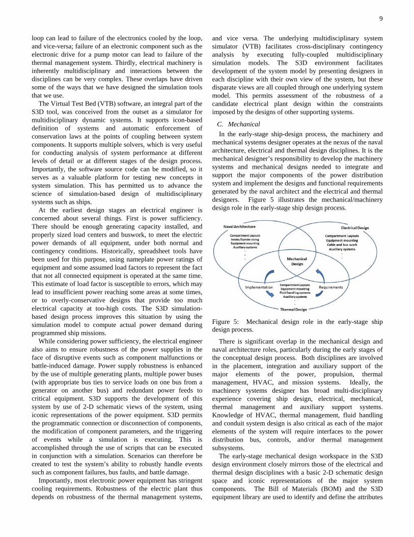
C. Mechanical In the early-stage ship-design process, the machinery and
mechanical systems designer operates at the nexus of the naval architecture, electrical and thermal design disciplines. It is the mechanical designer’s responsibility to develop the machinery systems and mechanical designs needed to integrate and support the major components of the power distribution system and implement the designs and functional requirements generated by the naval architect and the electrical and thermal designers. Figure 5 illustrates the mechanical/machinery design role in the early-stage ship design process.
Figure 5: Mechanical design role in the early-stage ship design process.
There is significant overlap in the mechanical design and naval architecture roles, particularly during the early stages of the conceptual design process. Both disciplines are involved in the placement, integration and auxiliary support of the major elements of the power, propulsion, thermal management, HVAC, and mission systems. Ideally, the machinery systems designer has broad multi-disciplinary experience covering ship design, electrical, mechanical, thermal management and auxiliary support systems. Knowledge of HVAC, thermal management, fluid handling and conduit system design is also critical as each of the major elements of the system will require interfaces to the power distribution bus, controls, and/or thermal management subsystems.
The early-stage mechanical design workspace in the S3D design environment closely mirrors those of the electrical and thermal design disciplines with a basic 2-D schematic design space and iconic representations of the major system components. The Bill of Materials (BOM) and the S3D equipment library are used to identify and define the attributes
10
of the elements of the ship system that have been assembled in the mechanical systems design environment. In addition to the typical electrical and thermal management interfaces, selected systems and/or components will require specialized auxiliary systems that are large and/or complex enough that they must be captured in the early-stage design process. Consideration of installation, removal and maintenance access for major components can also be important at this stage in the process.
Effective visualization and accurate communication of the hull layout and the physical arrangement and interconnection of the major ship system components is vital to both the naval architect and mechanical designer. The 3D visualization tool in the naval architect’s workspace can provide an overall view of the hull layout down to more detailed equipment arrangements at the compartment or deck level and will be the primary method of communicating the results of the machinery layout and design activities. An external full-featured 3-D solid modeling platform will likely also be a vital element of the mechanical designer’s “toolbox” particularly as the conceptual design progresses through the latter stages of the design spiral. The ability to easily import and export solid models from external modeling packages into the 3D visualization workspace is a critical feature of the S3D design environment. Revision control and configuration management will also be critical to the collaborative design process.
The 3D visualization workspace enables the naval architect to distribute the integrated power and thermal management systems throughout the hull with arrangement of the major elements driven by functionality, damaged stability/floodable length calculations, and the overall center of gravity of the ship. Once the basic layout of the major components has been defined, the mechanical designer can begin to address the more detailed integration of the equipment into the hull, including the initial design of structural supports and mounting for the major equipment. The mechanical designer refines the equipment arrangement at the compartment level including allocation of required maintenance access spaces, identification and placement of auxiliary support systems (e.g. firefighting, lubrication and ventilation systems) and initial sizing and routing of intakes/uptakes, piping and electrical distribution busses. This activity will require effective communication and collaboration with the naval architecture, electrical and thermal design disciplines.
The 3D visualization tool allows the mechanical designer to insert and manipulate solid models of the equipment but the capabilities of the 3D modeling features in the S3D environment are necessarily limited. Full-featured solid modeling design and analysis software tools (e.g. Rhino, SolidWorks, Catia) external to the S3D environment will be used to perform more detailed solid modeling and supporting analyses.
Analysis performed within the mechanical designer’s workspace will likely be limited to basic structural calculations and the sizing and design of liquid and air handling systems. Comprehensive structural design/analysis will take place during detailed design of the ship but structural
support for major equipment must be considered in early-stage design because of its potential impact on weight distribution and hull structure. Consideration of shock mounting and vibration isolation should also be included in early-stage design. Commercially available solid modeling packages typically include integrated finite element analysis capabilities that can be applied to structural, thermal and fluids analysis. External modeling enables the designer to quickly size major structural supports and capture volume requirements for integration back into the S3D solid model
In addition to layout and routing of the ductwork, advanced solid modeling packages can also support sizing and pressure drop calculations for the intakes/uptakes for gas turbines. Correct sizing is important because of the impact on engine performance and because the intake/uptake volumes can be quite significant, spanning multiple decks and/or compartments. Sizing and pressure drop calculations for seawater and freshwater piping systems (based on flowrates provided by the thermal designer) will also be performed by the mechanical designer. Initial calculations provide insight into pumping power requirements which can be reflected back to the electrical and thermal design disciplines.
D. Thermal In the “Navy after Next”, shipboard thermal management
will be an increasingly critical requirement in the early-stage ship design process. It has become clear that the global impact of thermal management auxiliaries and associated powering, maintenance, and operator effort will be even more burdensome than in the past and, if not managed properly, will contribute heavily to continued increases in size, weight, volume, and cost of the ship. In addition, changes in battle space doctrine, with an increased emphasis on operations in the littoral and net-centric warfare, will continue to place pressure on traditional design practices and continue to impact the performance of conventional thermal-electrical-mechanical components in unpredictable ways.
In the not so distant past, early-stage ship design involved a rough accounting of major thermal loads, followed by definition of auxiliary needs in an ad hoc way. Fortunately this situation is rapidly evolving for the better. However, since definition of a complete thermal design requires detailed knowledge of the geographical layout of the entire ship system, thermal management component selection and distribution have habitually occurred later in the design cycle. In addition, power and cooling subsystems have traditionally been designed in separate work groups, on a disjointed timeline, with results that are far from optimal. It is now recognized that these subsystems are tightly interdependent and it is increasingly understood that differing reliability and survivability approaches will cause their performance to impact unfavorably on each other. Succinctly stated, tightly interdependent subsystems are difficult to design, particularly in the early stages of the traditional spiral design process. Yet mistakes made in this early process will have significant, and potentially debilitating, impact on the outcome.
In early-stage ship design, accurate projection of all
11
auxiliary loads and consideration of the physical, geographical layout of the thermal management system is absolutely essential to enabling its more-efficient or near-optimal design configuration. This circumstance demands the development of more capable and highly integrated early-stage design tools for the ship-system thermal plant. These tools must allow for cross-disciplinary interaction and verification of key thermal design features while also addressing the impact that mechanical, electrical, and thermal subsystems might have on each other. It is also essential that the technical architecture of the thermal plant map directly over to candidate mechanical-electrical systems such that the evolving thermal design is current and such that the information available allows for early identification of significant issues as they arise. Ultimately this process requires the ability to perform and validate detailed thermal-electrical-mechanical co-simulations that address continuity of service and dynamic reconfiguration of the load management system. However, in the early-stages of the design process, the most important need is for reliable, automated accumulation of baseline data and information that describes the evolving thermal load structure. From this information the thermal designer may then select methods of load management that are appropriate to the situation. Clearly, the tools to be used must define any notional design architecture in sufficient detail to fully quantify the demands likely to be placed on the thermal management system. This topic, the accumulation of good upfront information in the early stages of design, is the focus of the following paragraphs.
Ultimately, an interdisciplinary design framework is envisioned that enables rapid scoping of the total ship thermal system in the presence of detailed interaction with all other players. The framework must address three major challenges that are faced when performing system-level thermal design. First, complex interactions exist between shipboard thermal and mechanical-electrical systems that require a total-system approach. Thus, if many candidate designs are to be considered, explored, and evaluated, a highly flexible and reconfigurable design environment is required. Second, high-fidelity models of thermal system components are typically too computationally expensive and time consuming to enable rapid fire sorting of design options. These models are typically developed in disparate software packages that inhibit ready integration with an automated, early-stage design tool. Third, when considering system configurations and/or damage scenarios, many of the parameters that define the system-level behavior are discrete and have a discontinuous effect on associated performance metrics. Examples include choices between various types of energy storage elements (e.g., batteries, flywheels, capacitors) or failure of individual components (e.g., a diesel generator or a chilled water loop) in a damage scenario. The above aspects of the early-stage, total-ship system design process have significant impact on methodologies that can reasonably be used for design space exploration. Thus, it is even more important that good, baseline load information be available as early in the design process as possible.
1) Thermal Management Load Summary Development (INPUTS):
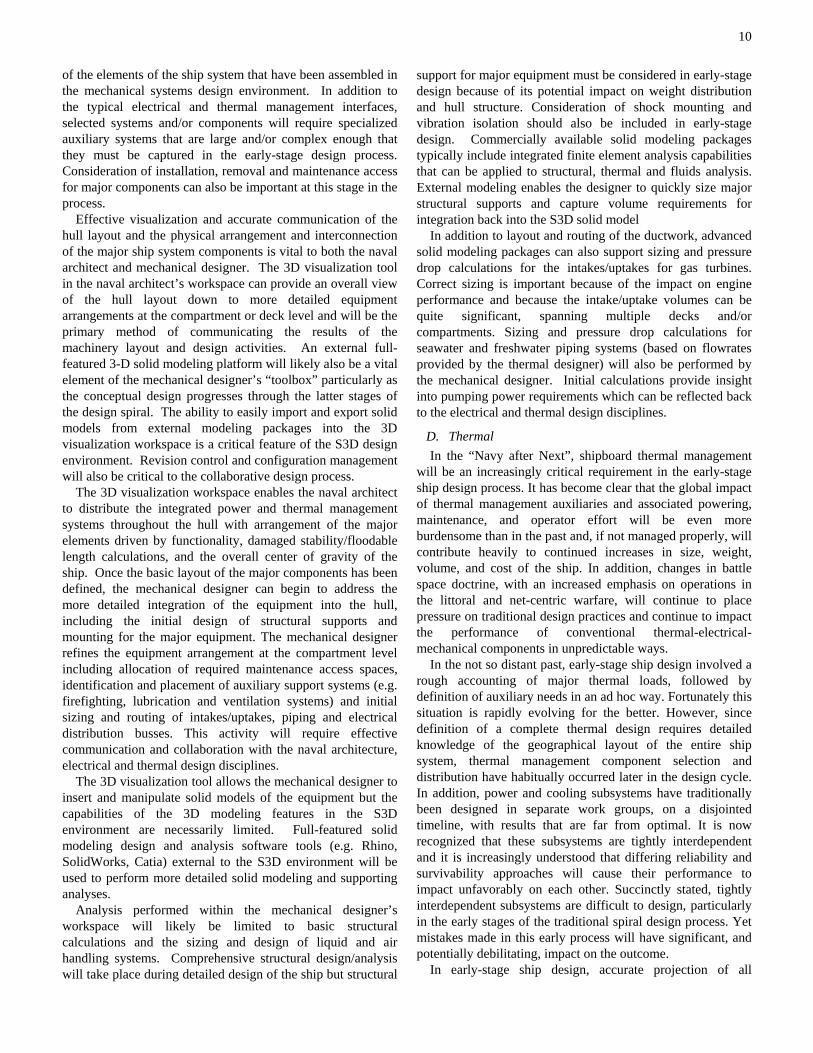
The thermal management community is fundamentally a service provider to the ship architect and ultimately dependent on the ship-system electrical and mechanical communities for reliable, accurate, and complete load information. The thermal engineer cannot fabricate load data and must rely on colleagues to provide workable baseline load data as the early-stage design evolves. Yet, at the same time, the thermal framework is ultimately an integrated element of the power and mechanical architectures and, in the end, will impose significant demands and constraints on both. Thus the interactions depicted in Figure 6 must occur.
Figure 6: Thermal Management Load Summary Development: INPUTS
Figure 6 is a graphical representation of the top-level interactions that should take place between the interdisciplinary team as the early-stage design evolves. The figure depicts an exchange and accumulation of detailed load data where the arrows indicate the two-way (actually multiple two-way) interchange of information, accompanied by a dialogue, that must be a continuous process amongst all stakeholders. The controls aspect of the problem is not explicitly shown. However, it is recognized that the work of the controls engineer will cut across all functional areas and ultimately be the glue that holds the design process together. It should not be assumed that what the designer imagines is capable of being controlled.
The product of the input process is indicated in the “inputs” box in Figure 6. The bullets in this box recognize the necessity for a detailed listing of those attributes that are essential to constructing an aggregated description of loads and load profiles expected to be experienced in any particular rendition of an early-stage design. The listing is not necessary complete or all inclusive, but it does reflect the nature of the task. Load data provided to the thermal engineer are expected to be the total connected requirement to include critical component redundancies, both as a function of mission profile and ambient environmental conditions.
At this level of detail, the process is no different from what has occurred historically. What is expected to be different is the nature of the collaborative environment and the manner in which the interchange and aggregation occur, both of which have been adequately described elsewhere in this paper. The
12
goal of this first step is to accomplish rapid and automated collaboration across the entire scope of involved disciplines and within the entire realm of human resources. The result of this collaboration, an aggregation of a detailed and documented load list, is clearly a necessary product of the early-stage design process. The process has the added benefit of providing a “feel” for the tradeoffs involved in providing a thermal management solution for the early-stage design.
2) Thermal Management Load Summary Development (PROCESS):
The interchange described in the previous paragraphs is effectively one of “bookkeeping”, i.e. the process of accumulating, organizing, and cross-checking specific thermal management load data. This is clearly a process suited to a digital environment; it may be automated, cross referenced, and interactive. However, the next logical step in the early-stage design process demands both specific expertise and detailed subject area knowledge, along with informed engineering judgment, that follows in part from the “feel” that was developed during the aggregation of inputs. This next step is the parsing and assignment of load data to a specific thermal management resource.
Current technology for successful total ship system thermal management depends on a variety of flowing commodities that are distributed throughout the ship to remove and/or redistribute waste heat. Currently these commodities include seawater, fresh water, chilled water, refrigerated air, ambient air ventilation, lubricant/coolant, and electric power. Much of the increased heat load on future ships is expected to be managed within an actively cooled air distribution (HVAC) system or directly by the chilled water system [10]. Thus, the chilled water and refrigerated air modes are experiencing increased emphasis. In addition, future ships almost certainly must allow for various means of energy recovery and energy storage, attributes that have not been of particular concern in the past. Finally, energy conservation and fuel costs may well drive the Navy to introducing new technologies on future new or existing ship classes. These circumstances may well introduce additional “commodities”, i.e., added means of managing thermal energy.
A warship is operated under various operating conditions. Within each condition, various groups of loads are energized (or de-energized) to fulfill the needs of ship systems. Therefore the particular configuration of the electrical-mechanical system aboard a warship is dynamic in nature. This implies that the thermal management system must also be dynamic in nature. Shipboard energy use is typically assessed under four operational conditions or modes: shore (dockside), anchor, cruise, and battle. Dependent upon the particular function of that system, each of these conditions has its own energy management implications for each of the various types of shipboard systems. For example, a warship’s propulsion, weapon, and radar systems would clearly demand increased energy, and therefore more heavily depend upon thermal management, in the battle mode. In contrast certain auxiliary systems might use more energy in battle mode than at anchor—but these same systems might also demand even
more energy in cruise mode than in battle mode. All of these considerations should be quantified and weighed during early-stage design. With few exceptions, combat effectiveness must clearly take priority over energy efficiency under battle conditions. However cruise, anchor and dockside conditions should almost always emphasize energy efficiency.
Finally, due to practical implications of the previous paragraph, electrical-mechanical and shipboard “hotel loads” are commonly categorized as either “vital” or “non-vital”. For vital loads, two separate paths (normal and alternate) are typically provided. These designations are, in part, used to ensure priority service restoration for essential shipboard systems. Clearly, this approach is related to considerations of warship survivability, reconfigurability, and redundancy.
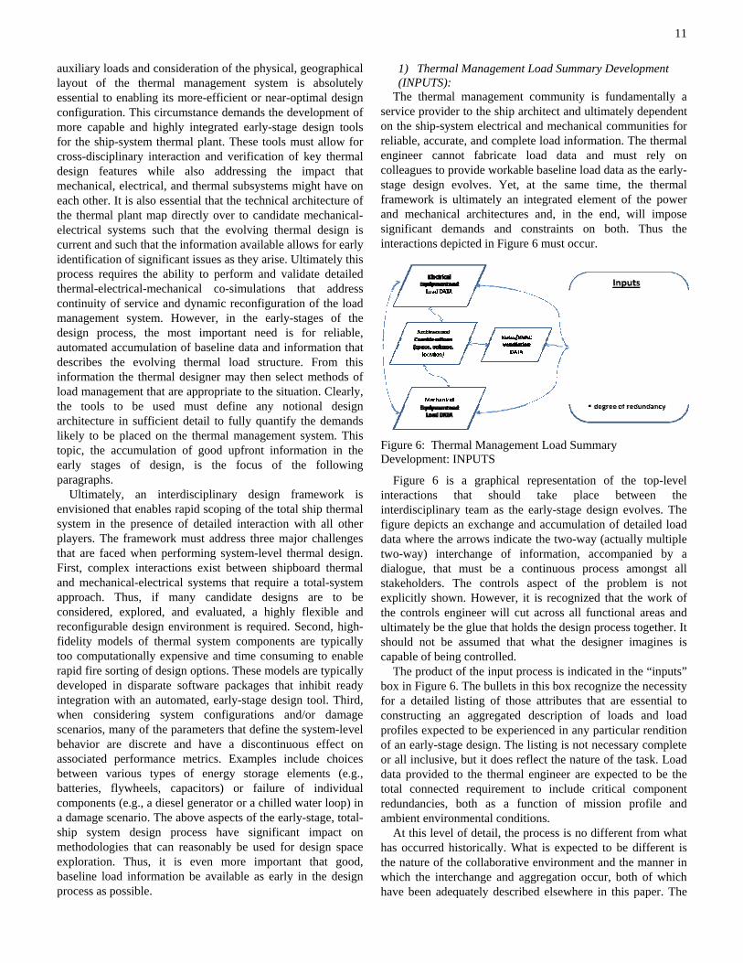
Given these realities, the immediate concern remains to identify, parse, and partition loads amongst the various resources that might be used to manage these loads. Figure 7 attempts to capture a description of the process.
Figure 7: Thermal Management Load Summary Development: PROCESS
Figure 7 indicates that the development of a load summary in the early stages of design involves a “clearing house” approach for input aggregation that is complete and thorough as well as on-going and continuous. Whereas modifications to early-stage inputs are clearly necessary, there must be a process which ensures that ALL loads are identified and that each of these loads is recognized and considered, and that each load is associated with a particular early-stage conceptual approach for management. Thus the “clearing house” terminology is used. This terminology implies a “check-in” and “check-out” process, complete with a pre-defined concept identification “label”, such that ideas may later be categorized, sorted, and assigned against a concept or group of concepts. This process is also readily amenable to digital implementation along with multi-channel feedback and confirmation from and to each stakeholder.
As mentioned at the beginning of this section, the next logical step in the load summary development process involves specific thermal management expertise and subject area knowledge. This step may ultimately allow for incorporation of expert digital systems and/or “agents” capable of learning and reacting to various considerations
13
during the decision making process. However, in a simplistic sense the process is straightforward. Various loads must be parsed among thermal management resources as a function of the mission-based tactical situation, operational alignment, environmental conditions, and the various desires for redundancy, survivability, and/or reconfigurability. These loads must also be assigned either as vital or non-vital. In the interest of later reconstruction, this process must not be haphazard. In fact the process should be highly organized, well documented, and configured to ease the process of after-the-fact reconstruction. Finally, and importantly, the instantaneous status of the process must be communicated across interdisciplinary lines for reasons that have been clearly stated previously, i.e., the integrated nature of the outcome and the demands and constraints that the particular outcome will impose on the total ship-system. Clearly this step is where informed innovation and creativity are important to the process.
A load classification process is indicated in Figure 7. The “conventional” means of load management are depicted in the center portion of the graphic, with a place-holder for energy recovery and reutilization at the bottom. The outcome of the assignment process is a notional load handling “inventory” that captures a summary of thermal management methods and sources and for the first time specifically identifies real or notional auxiliary systems to manage these accumulated loads. In the early-stage design process, this inventory is a first rendition (“first draft”) of thermal management at the total ship-system level. This outcome is preliminary, and essential, to the next steps in the early-stage design process, i.e., initial scoping of the thermal plant configuration followed by a preliminary sizing calculations.
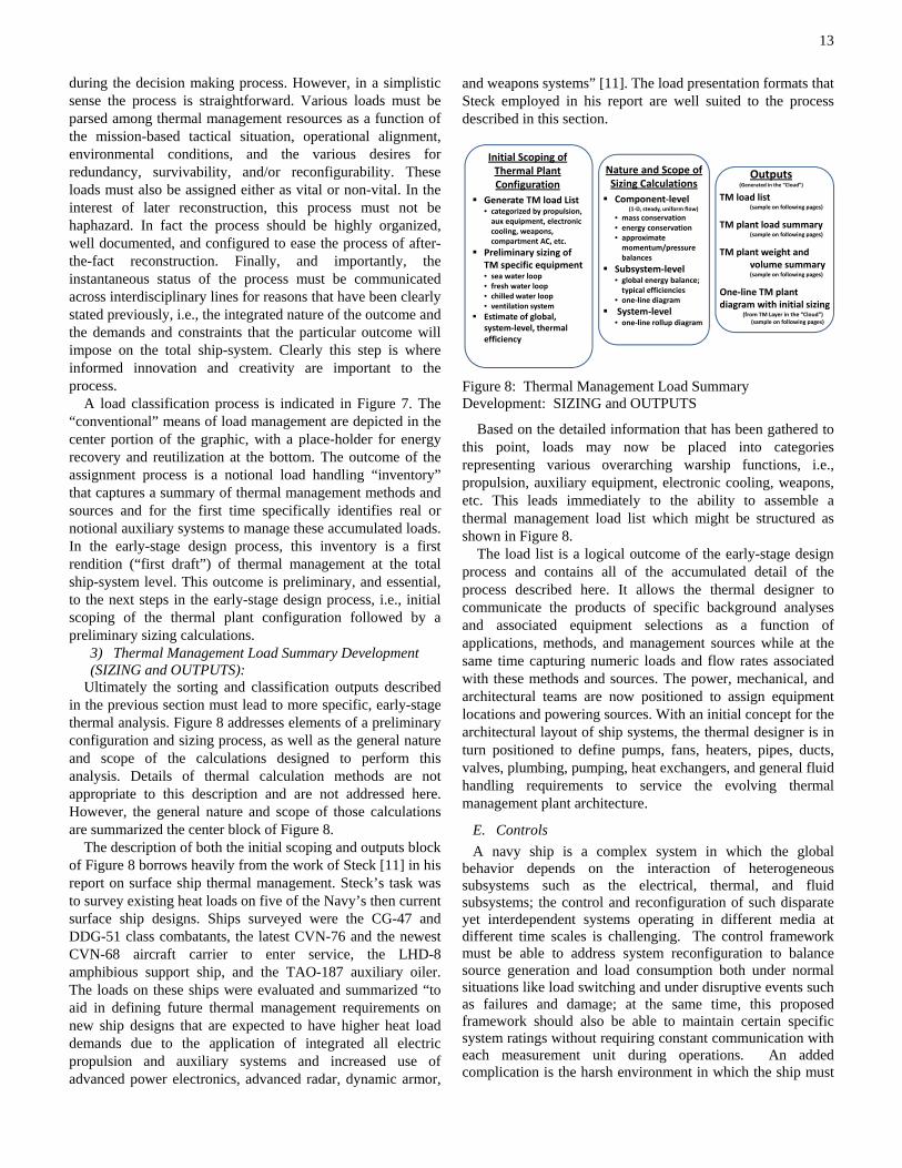
3) Thermal Management Load Summary Development (SIZING and OUTPUTS):
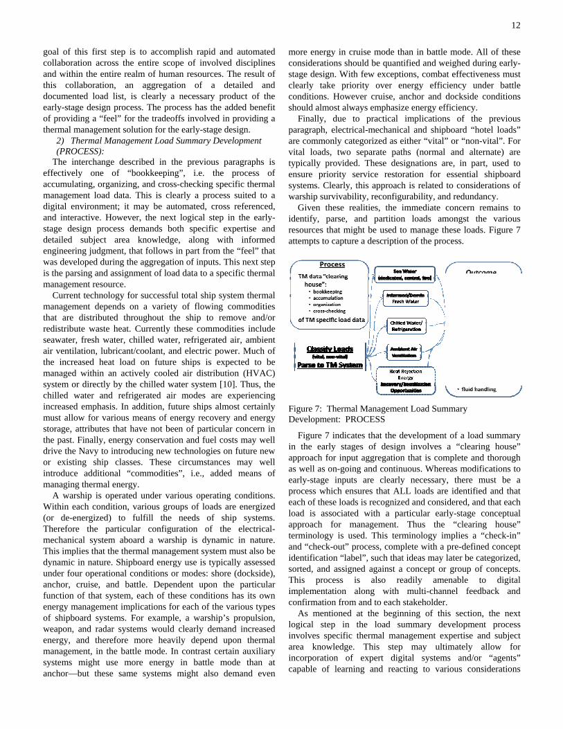
Ultimately the sorting and classification outputs described in the previous section must lead to more specific, early-stage thermal analysis. Figure 8 addresses elements of a preliminary configuration and sizing process, as well as the general nature and scope of the calculations designed to perform this analysis. Details of thermal calculation methods are not appropriate to this description and are not addressed here. However, the general nature and scope of those calculations are summarized the center block of Figure 8.
The description of both the initial scoping and outputs block of Figure 8 borrows heavily from the work of Steck [11] in his report on surface ship thermal management. Steck’s task was to survey existing heat loads on five of the Navy’s then current surface ship designs. Ships surveyed were the CG-47 and DDG-51 class combatants, the latest CVN-76 and the newest CVN-68 aircraft carrier to enter service, the LHD-8 amphibious support ship, and the TAO-187 auxiliary oiler. The loads on these ships were evaluated and summarized “to aid in defining future thermal management requirements on new ship designs that are expected to have higher heat load demands due to the application of integrated all electric propulsion and auxiliary systems and increased use of advanced power electronics, advanced radar, dynamic armor,
and weapons systems” [11]. The load presentation formats that Steck employed in his report are well suited to the process described in this section.
Figure 8: Thermal Management Load Summary Development: SIZING and OUTPUTS
Based on the detailed information that has been gathered to this point, loads may now be placed into categories representing various overarching warship functions, i.e., propulsion, auxiliary equipment, electronic cooling, weapons, etc. This leads immediately to the ability to assemble a thermal management load list which might be structured as shown in Figure 8.
The load list is a logical outcome of the early-stage design process and contains all of the accumulated detail of the process described here. It allows the thermal designer to communicate the products of specific background analyses and associated equipment selections as a function of applications, methods, and management sources while at the same time capturing numeric loads and flow rates associated with these methods and sources. The power, mechanical, and architectural teams are now positioned to assign equipment locations and powering sources. With an initial concept for the architectural layout of ship systems, the thermal designer is in turn positioned to define pumps, fans, heaters, pipes, ducts, valves, plumbing, pumping, heat exchangers, and general fluid handling requirements to service the evolving thermal management plant architecture.
E. Controls A navy ship is a complex system in which the global
behavior depends on the interaction of heterogeneous subsystems such as the electrical, thermal, and fluid subsystems; the control and reconfiguration of such disparate yet interdependent systems operating in different media at different time scales is challenging. The control framework must be able to address system reconfiguration to balance source generation and load consumption both under normal situations like load switching and under disruptive events such as failures and damage; at the same time, this proposed framework should also be able to maintain certain specific system ratings without requiring constant communication with each measurement unit during operations. An added complication is the harsh environment in which the ship must
Initial Scoping ofThermal Plant Configuration
Generate TM load List• categorized by propulsion, aux equipment, electronic cooling, weapons, compartment AC, etc.
Preliminary sizing of TM specific equipment• sea water loop• fresh water loop• chilled water loop• ventilation systemEstimate of global, system‐level, thermal efficiency
Outputs(Generated in the “Cloud”)
TM load list(sample on following pages)
TM plant load summary(sample on following pages)
TM plant weight and volume summary(sample on following pages)
One‐line TM plant diagram with initial sizing
(from TM Layer in the “Cloud”)(sample on following pages)
Nature and Scope of Sizing CalculationsComponent‐level
(1‐D, steady, uniform flow)
• mass conservation• energy conservation• approximate momentum/pressure balances
Subsystem‐level• global energy balance; typical efficiencies
• one‐line diagram
System‐level• one‐line rollup diagram
14
operate, with the need for reconfiguration and continuing operations in the face of potentially significant damage to limited sources and a limited distribution network. In addition, the ship control system should be structured to have different goals in different operating conditions: during battle conditions or restricted maneuvering, maintaining operations is paramount, but during normal cruising operations or at anchor, energy-conservation measures may impact operations.
To date, the S3D environment has not been used to design, model or simulate control systems, so the following is a general discussion of the controls design problem; further consideration must be put toward determining the incorporation of controls design in S3D.
For effective implementation of distributed optimization and control techniques, system models should effectively reflect both the structural and dynamic aspects of the system. The dynamics of multifunctional heterogeneous units in the ship power system can be arbitrarily complex depending on underlying elementary components, the way they interact, the condition of the operating environment, and the operating platform. However, the dynamics of individual components are usually much simpler. Various levels of abstraction are needed for effective modeling, analysis, and control of such complex systems.
To properly model the dynamic behavior of ship systems, both the continuous nature of the operations and the discrete action of components such as switches must be considered; a ship system is typically a hybrid system in which both continuous and discrete states influence its behavior. In order to address this hybrid dynamical nature of a ship system, a hybrid controls approach needs to be developed. This hybrid control can be defined by a continuous part, which may involve Multi-Agent Systems (MAS) and different optimization algorithms, and by a discrete part which may involve the supervisory and reconfiguration actions.
Effective control techniques, such as model predictive control (MPC) and supervisory control, would allow performance objectives to be represented explicitly as a multi-variable optimization problem and can be applied to complex dynamic including ones that are even-driven as well as systems with long delays or dead times [15]. The distributed nature of the targeted power system suggests a decentralized control structure wherein the overall problem is decomposed into smaller sub-problems that individual controllers solve cooperatively. Each controller can manage a single system unit, and groups of controllers report to higher-level coordinators that manage the interaction between the various subsystems.
The successful control system must contain a set of reconfiguration control strategies that depend upon the operating scenario, and must be able to accomplish the following basic steps:
1. Evaluate and analyze system status in real time. 2. Formulate the reconfiguration objective. 3. Select and implement the reconfiguration strategy.
The following describes a possible process to achieve the design of a successful control system.
Design Process
The first step toward control design is the determination of the control specifications and objectives. These objectives will be formulated from the electrical, thermal and fluid subsystems. However, resources in each subsystem are limited and the subsystems might have conflicting objectives and goals. Therefore, optimizing the objectives such as utilization of resources is required for long term operations, especially under battle conditions where the optimized use of resources is very important and survivability is of major concern. For example, during normal operations, servicing a load in one zone using pumps in another zone is not preferred; however, this constraint may be violated in reconfiguration during fault situations in order to improve survivability. In order to determine a survivable configuration, a multi-objective optimization must be addressed using code external to the S3D environment such as described in [12] and [13].
The second step of the control design is the verification of the controllability and closed-loop stability criteria. Traditionally, modeling and simulation are used to develop controllers and conduct the controllability and the stability analysis, as well as testing the proposed control feedback to get a better understanding of expected outcome. This provides a low-risk approach towards validation of the control and reconfiguration framework but also allows capturing the impact of reconfiguration decisions on the integrated system. The controllability and the stability analysis will be conducted using external tools such as described in [14]. In this control design process, the analysis will utilize the models of ship’s subsystems and load data in the cloud for testing and validation. Also, different candidate designs will be considered during this analysis, and the candidate that satisfies the control criteria will be selected by the control as the best candidate design.
V. DESIGN ANALYSIS AND COMPARISON In early-stage design, the need exists to compare and
contrast many different designs in order to narrow the design space or to identify the strengths and weaknesses of specific designs. The Contender Evaluation and Selection Technique (CONTEST) was developed in the late 1960’s by the Navy to provide a structured approach with a quantifiable ranking process for the evaluation of technical proposals [15].
The structure of a CONTEST evaluation includes questions that are subdivided into major and minor categories, called Factors and Groups. The categories are designed to be of similar importance, so strength in one area cannot dominate the results. For each question, candidates are scored based on a relative comparison to either a baseline expectation or an established norm from within the population of candidates. The scoring, intended to avoid the typical challenges of providing a rarified gradation of scores, is simply based on whether a candidate is comparable, superior, or inferior to the established expectation or norm. The resulting scores tend to be insensitive to overwhelming superiority in a single category, whereas the winning candidate typically displays balanced excellence across all of the evaluation criteria.
The CONTEST process provides an organizational structure

15
and ranking process that is systematic, transparent, and justifiable. It is easily able to capture the contributions of a variety of subject matter experts and document the rationale behind the scoring. CONTEST has also proven to be an effective tool for selection of alternatives early in the design stage when a complete set of requirements cannot be defined. For all of the above reasons, the CONTEST method is particularly well-suited to the candidate architecture evaluation for the ESRDC.
ESRDC is developing a set of evaluation questions tailored to the analysis of electric-drive ships and specifically addressing the electrical distribution architecture such as Medium Voltage AC (MVAC), High Frequency AC (HFAC), Medium Voltage DC (MVDC), and hybrid versions thereof.
Figure 9: ESRDC CONTEST Evaluation Matrix Outline
The basic structure of the ESRDC CONTEST matrix, shown in Figure 9, has been proposed by the UT-Center for Electromechanics and will evolve as additional input is integrated from the other members of the ESRDC. The preliminary major evaluation categories, or Factors, are Functionality, Thermal, Packaging and Integration, Naval Architecture, and Programmatics. Each factor is subdivided into groups and if necessary subgroups of questions across several topics. The Functionality factor is focused on the basic electrical functionality of the candidates. Because thermal effects are important for both the power generation elements and the loads they serve, they are considered in detail in the Thermal factor. The Naval Architecture factor considers aspects of the power system architecture in the context of a naval vessel. The size, weight, and interconnection of the major components of the power system are evaluated in the Packaging and Integration factor. Finally, the Programmatics factor addresses cost, development, lifecycle and required technology development.
The CONTEST matrix currently resides in the S3D cloud environment. Subject matter experts are involved both in developing the matrix and in using the matrix for evaluation of
designs. The accessibility of the S3D cloud tool facilitates the employment of the CONTEST process across a geographically distributed group of subject matter experts involved in the design and external to the design.
VI. VISION AND FUTURE WORK The initial use of S3D by the ESRDC has led to several new
requirements and to the discovery of some gaps in our capabilities. This section details some specific areas envisioned for improvement.
A. Software advances In order to better support the execution of very large
simulations, a key challenge to be tackled is the scaling of the back end (the simulation engine) while using conventional cloud resources. Typically the cloud computing environment is composed of heterogeneous resources, perhaps from multiple administrative domains that are geographically dispersed and loosely coupled. This configuration complicates the fast solution of large tightly-coupled simulation problems. Although developers of some grid computing resources may strive to reach a common configuration, still the inherent nature of the cloud model is that the computers are loosely coupled and there are not provisions for high-speed exchange of data between computers. Yet to solve large problems, we must decompose a large simulation problem into many smaller pieces and communicate frequently and quickly between those pieces.
We have also concluded that the capabilities of the visualization environment need to be extended in order to create a more immersive experience and a more complete development environment for the user. The visualization environment should support rapid and easy movement between discipline-specific views of the ship systems. We will take advantage of opportunities the visualization tool may offer with respect to the extraction of physical details of the design, such as the approximate length of cable runs and pipes, and reflect these back into the system schematics. Conversely, the various simulation tools will likely be able to provide additional information, such as the temperature of components or the state and availability of certain devices, that can be propagated to the visualization environment. Improvements and refinements to the visualization tool offer the most promising medium for the distillation of large amounts of highly technical and discipline-specific information into generalizations that can be easily consumed by less technical stake holders and by those with substantially different technical backgrounds.
The S3D environment is deployed over the web using standard http(s) protocols. This allows the environment to be easily accessible to users regardless of their location and without requiring the installation of additional software on their computers. Although the underlying http protocols provide an unfettered means of communication, they suffer from verbose messages and general inefficiencies. The S3D environment must be more responsive to the user and must provide scalable tools and techniques that support the
16
movement of large amounts of data expediently and bi-directionally. The W3C consortium has recently updated the HTML5 specification and proposed some modifications to browsers that may permit more efficient communication. As this standard is accepted by industry we will look to adopt this and other technological advancements in order to support both the concurrent and collaborative nature of this environment and the distributed and massively parallel simulations that are to be run within the cloud infrastructure.
B. Model-integrated computing Model-integrated computing [17] is a formal system design
methodology that has gained momentum in recent years as a sound methodology for applying computer-based modeling and synthesis methods to a variety of problem domains, including real-time [18] and cyber-physical systems, in which power systems are an example. The underlying models formally capture relevant properties of the system to be developed and can be used directly to automatically generate implementation code and other engineering artifacts that are tedious and error-prone to produce manually. Model-integrated computing (MIC) techniques can be used to raise the abstraction of control theoretic/optimization methods and make them available to domain engineers. In particular, a carefully designed domain-specific meta-modeling language will allow specification of various technology elements along with the underlying performance and reliability measures in an integrated manner using formal model-integrated computing techniques. Available generic meta-modeling environment tool suites currently used in several DoD sponsored projects can be used to automatically generate code for models (including simulation models) as well as verification, management, and design support structures from a given set of performance, reliability and fault tolerance requirements.
We will develop a suite of translators that can synthesize the artifacts relevant for system execution and performance optimization. A particularly challenging translator would compose the system dynamics model from the component behavior models. The composition mechanism must take into consideration the model of computation employed. The proposed development plan aims to pass the design requirements in some appropriate way to the runtime platform for parameterizing an adaptive power management structure to incorporate the appropriate measurement and adaptation strategies ensuring that key specifications are met in the operational system.
C. Discipline-specific design To date, the supporting discipline-specific work has focused
on definition and description of a process for early-stage scoping of the various subsystems, which has led to the development of a software environment in which collaborative design can be accomplished. Now that the backbone is in place, further development will flesh out the use of the environment in design of ships and ship systems, incorporating those methods that are necessary as an inherent part of the S3D environment, facilitating transfer of models to
external programs where needed, and devising methods to store and share information derived from both internal and external processes. The vision for each discipline is outlined in Section IV above. The future work to be performed may include among its advances: • Construction of higher fidelity and more tightly integrated
discipline-specific design and analysis tools within the S3D environment.
• Definition of potentially large sets of design alternatives using design space exploration and visualization methods.
• Expansion of the supporting database to include the wide range of equipment necessary to accomplish this task, along with developing notional equipment that can be used to explore the possible.
• Collaboration among the disciplines to develop the design space visualization required to understand and grasp the impact of whole-ship design decisions.
• Incorporation of techniques and tools that address and quantify design considerations such as flexibility, redundancy, modularity, reconfigurability, cost, weight, volume, efficiency and survivability, and methods to present metrics in a manner that enhances total-ship design.
Regardless of what elements might appear in the foregoing list, the evolution of a general purpose, well-developed, early-stage design environment will build on the cohesiveness of the cross-discipline, consortium-wide collaboration built to date.
VII. CONCLUSIONS We have developed the basis of a collaborative design tool
for use in early-stage ship design. This environment is a needed advance to the early-stage design toolbox in that it enables simultaneous collaborative design across multiple disciplines and thus brings the interplay of multiple disciplines earlier in the design process. A wide range of disciplines has been involved in the development of this tool and the vision for future tool development is explored.
ACKNOWLEDGMENT Our appreciation goes to Terry Ericsen for being a driver in
this process, and to Bryan Tomer for valuable input throughout.
REFERENCES [1] P. A. Gale, “The ship design process,” in Ship Design & Construction,
Vol. 1, T. Lamb, Ed., Jersey City, NJ: The Society of Naval Architects and Marine Engineers, 2003, pp 1-40.
[2] F. Mistree, W. F. Smith, B. Bras, J. K. Allen, and D. Muster, "Decision-based design: A contemporary paradigm for ship design", Transactions, Society of Naval Architects and Marine Engineers, vol. 98, pp. 565-597, 1990.
[3] R. A. Dougal, B. Langland, and A. Monti, “Virtual prototyping as a mechanism for simulation-based design” in Proceedings of the 2007 Summer Computer Simulation Conference, San Diego, CA, pp. 1-6, 2007.
[4] J. V. C. Vargas, J. A. Souza, R. Hovsapian, J. C. Ordonez, T. Chiocchio, J. S. Chalfant, C. Chryssostomidis, E. Dilay, “Notional all-electric ship systems integration thermal simulation and visualization”, Simulation:
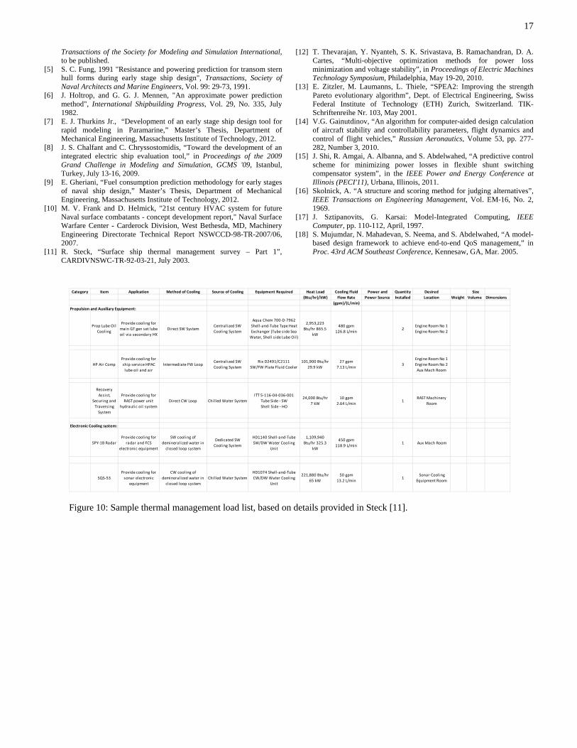
17
Category Item Application Method of Cooling Source of Cooling Equipment Required Heat Load Cooling Fluid Power and Quantity Desired Size(Btu/hr)/kW) Flow Rate Power Source Installed Location Weight Volume Dimensions
(gpm)/(L/min)Propulsion and Auxiliary Equipment:
Prop Lube Oil Cooling
Provide cooling for main GT gen set lube oil via secondary HX
Direct SW System Centralized SW Cooling System
Aqua Chem 700‐D‐7962 Shell‐and‐Tube Type Heat Exchanger (Tube side Sea Water, Shell side Lube Oil)
2,953,223 Btu/hr 865.5
kW
480 gpm 126.8 L/min
2Engine Room No 1 Engine Room No 2
HP Air CompProvide cooling for ship service HPAC lube oil and air
Intermediate FW Loop Centralized SW Cooling System
Rix D2491/C2111 SW/FW Plate Fluid Cooler
101,900 Btu/hr 29.9 kW
27 gpm 7.13 L/min
3Engine Room No 1 Engine Room No 2 Aux Mach Room
Recovery Assist,
Securing and Traversing System
Provide cooling for RAST power unit
hydraulic oil systemDirect CW Loop Chil led Water System
ITT 5‐116‐04‐036‐001 Tube Side ‐ SW Shell Side ‐ HO
24,000 Btu/hr 7 kW
10 gpm 2.64 L/min
1RAST Machinery
Room
Electronic Cooling system:
SPY‐1B RadarProvide cooling for
radar and FCS electronic equipment
SW cooling of demineralized water in closed loop system
Dedicated SW Cooling System
HD1140 Shell‐and‐Tube SW/DW Water Cooling
Unit
1,109,940 Btu/hr 325.3
kW
450 gpm 118.9 L/min
1 Aux Mach Room
SQS‐53Provide cooling for sonar electronic
equipment
CW cooling of demineralized water in closed loop system
Chil led Water SystemHD1074 Shell‐and‐Tube CW/DW Water Cooling
Unit
221,880 Btu/hr 65 kW
50 gpm 13.2 L/min
1 Sonar Cooling Equipment Room
Transactions of the Society for Modeling and Simulation International, to be published.
[12] T. Thevarajan, Y. Nyanteh, S. K. Srivastava, B. Ramachandran, D. A. Cartes, “Multi-objective optimization methods for power loss minimization and voltage stability”, in Proceedings of Electric Machines Technology Symposium, Philadelphia, May 19-20, 2010.
[5] S. C. Fung, 1991 "Resistance and powering prediction for transom stern hull forms during early stage ship design", Transactions, Society of Naval Architects and Marine Engineers, Vol. 99: 29-73, 1991. [13] E. Zitzler, M. Laumanns, L. Thiele, “SPEA2: Improving the strength
Pareto evolutionary algorithm”, Dept. of Electrical Engineering, Swiss Federal Institute of Technology (ETH) Zurich, Switzerland. TIK-Schriftenreihe Nr. 103, May 2001.
[6] J. Holtrop, and G. G. J. Mennen, "An approximate power prediction method", International Shipbuilding Progress, Vol. 29, No. 335, July 1982.
[7] E. J. Thurkins Jr., “Development of an early stage ship design tool for rapid modeling in Paramarine,” Master’s Thesis, Department of Mechanical Engineering, Massachusetts Institute of Technology, 2012.
[14] V.G. Gainutdinov, “An algorithm for computer-aided design calculation of aircraft stability and controllability parameters, flight dynamics and control of flight vehicles,” Russian Aeronautics, Volume 53, pp. 277-282, Number 3, 2010. [8] J. S. Chalfant and C. Chryssostomidis, “Toward the development of an
integrated electric ship evaluation tool,” in Proceedings of the 2009 Grand Challenge in Modeling and Simulation, GCMS '09, Istanbul, Turkey, July 13-16, 2009.
[15] J. Shi, R. Amgai, A. Albanna, and S. Abdelwahed, “A predictive control scheme for minimizing power losses in flexible shunt switching compensator system”, in the IEEE Power and Energy Conference at Illinois (PECI'11), Urbana, Illinois, 2011. [9] E. Gheriani, “Fuel consumption prediction methodology for early stages
of naval ship design,” Master’s Thesis, Department of Mechanical Engineering, Massachusetts Institute of Technology, 2012.
[16] Skolnick, A. “A structure and scoring method for judging alternatives”, IEEE Transactions on Engineering Management, Vol. EM-16, No. 2, 1969. [10] M. V. Frank and D. Helmick, "21st century HVAC system for future
Naval surface combatants - concept development report," Naval Surface Warfare Center - Carderock Division, West Bethesda, MD, Machinery Engineering Directorate Technical Report NSWCCD-98-TR-2007/06, 2007.
[17] J. Sztipanovits, G. Karsai: Model-Integrated Computing, IEEE Computer, pp. 110-112, April, 1997.
[18] S. Mujumdar, N. Mahadevan, S. Neema, and S. Abdelwahed, “A model-based design framework to achieve end-to-end QoS management,” in Proc. 43rd ACM Southeast Conference, Kennesaw, GA, Mar. 2005.
[11] R. Steck, “Surface ship thermal management survey – Part 1”, CARDIVNSWC-TR-92-03-21, July 2003.
Figure 10: Sample thermal management load list, based on details provided in Steck [11].