Embed Size (px)
Citation preview

A Co-manipulation Robotic System for Brain Biopsies
Pedro Miguel Pires [email protected]
Instituto Superior Tecnico, Universidade de Lisboa, Lisboa, Portugal
June 2016
Abstract
Brain diseases affect a substantial amount of people worldwide, and brain surgery is in manycases the most efficient, but complex, therapeutic procedure to treat them. The evolution of robotics,especially in the field of human-machine interaction, has provided more precise, less invasive procedures,allowing to reduce human errors, and to overcome certain limitations of the conventional brain surgeries.In this project, a robotic solution involving the KUKA LWR 4+ and the Polaris Spectra opticaltracking system has been implemented, in order to perform brain surgeries requiring precise targetingof structures within the brain. The robot’s positioning task is performed by a co-manipulation setupbetween the surgeon and the robot, through a virtual impedance environment. Two simulated brainbiopsies were performed using a phantom specifically designed for the purpose. One was performedat Hospital Santa Maria in Lisbon, following the current medical procedures and using the clinicalneuronavigation instrumentation. The other was performed at the Surgical Robotics Lab of InstitutoSuperior Tecnico, using the neuronavigation robotic system. The targeting errors of both approacheswere measured, and then compared. The errors obtained with the clinical approach, from the medicalimage acquisition to the biopsy execution, were 3.74mm±1.56mm and 3.77◦±2.23◦ for target positionand trajectory orientation, respectively. The errors obtained with the neuronavigation robotic systemwere 2.46mm± 1.04mm and 3.61◦ ± 2.75◦, for target position and trajectory orientation, respectively.The results of this project reveal a 34% decrease in position error and a 4% decrease in orientationerror with the robotic system.Keywords: Robotic Brain Biopsy, Co-manipulation, Virtual Impedance Control, Light WeightRobotics, Image Registration
1 Introduction
In surgery there is a constant search of new tech-niques that allow better results for the patientscombined with a improved performance for Sur-geons. The goals of using robots in surgeries are toprovide improved diagnostic and therapeutic capa-bilities. They allow a less invasive experience whencompared with an open surgery for the same pur-pose, and at the same time provide the means toperform more precise interventions.The current project is built on the previous projectsat the Surgical Robotics Lab, and is divided intotwo parts. The first part is to build a Simulink Real-Time model connecting the system devices used inthe brain biopsy procedure. The second part is tocreate a robot assisted surgical environment to per-form a brain biopsy, and to validate it against thestandard procedure on a cranial phantom.The robotic environment consists of a KUKA LWR4+ robotic arm and the Polaris Spectra opticaltracking system. These two elements are connectedand synchronized to each other. In the case study
of this project, the surgical assisted robotic envi-ronment is tested by performing a brain biopsy ona phantom. All the concepts of the robotic environ-ment are based on the current procedure performedat Hospital Santa Maria.
2 Work developed at Surgical Robotics Lab
In [3] a robotic system to assist orthopaedic sur-geons to perform hip resurfacing prosthesis surgerywith high accuracy and precision, by providing hap-tic guidance during the bone drilling stage of theprocedure was developed (figure 1).In [4] the goal was to adapt the co-manipulationmethod developed in [3] to the hip resurfacing sur-gical procedure but to perform a brain biopsy (fig-ure 2).
1

Figure 1: Co-manipulation robotic solution for hipresurfacing surgery [3].
Figure 2: Surgeon performing the biopsy assistedby the co-manipulation robotic solution [4].
3 Devices
3.1 KUKA Lightweight Robot 4+
The KUKA Lightweight Robot 4+ (figure 3(a))is one of the most innovative robotic manipulators,product of a research collaboration between the In-stitute of Robotics and Mechatronics at the GermanAerospace Centre (DLR) and the company KUKARoboter. The main features that make the KUKALWR 4+ one of the state of the art robotic manip-ulators are the fact it can support his own weight(it has a 1:1 power-to-weight ratio), its kinematicredundancy that makes it resemble the human armand torque sensors in each of the joints. The combi-nation of position sensors and torque sensors makesit possible to implement not only position controlbut also impedance control. KUKA LWR 4+ hasseven degrees of freedom (DOF). In figure 3(b) itis illustrated the KUKA LWR 4+ axis and joints’numbering. The KUKA LWR 4+ can be inter-faced in two distinctive manners, directly in thecontroller console using the KUKA Robot Language(KRL) or by using the KUKA Fast Research Inter-
(a) (b)
Figure 3: a) KUKA LWR 4+ in Surgical RoboticsLaboratory at IST b) KUKA LWR 4+axis andjoints’ numeration [6].
(a) (b)
Figure 4: a) Polaris Spectra b) and a reference toolwith markers [2].
face (FRI) API. In this project the FRI was used toperform the communication with the KUKA LWRcontroller.
3.2 Polaris Spectra
The Polaris Spectra is a tracking device (fig-ure 4(a)). It can track the 3D position and ori-entation of passive markers attached to tools (fig-ure 4(b)) with high accuracy. It emits infrared lightto wirelessly detect and track a tool’s position andorientation in all six degrees of freedom. The posi-tion and orientation of each tool is tracked and dis-played within the simulation software in real time.The Polaris Spectra hardware acquires the pose ofpassive markers in relation to the Polaris base refer-ence frame with a 60Hz frame rate and an accuracyof 0.3mm.
3.3 Devices’ Communication
One of the main goals of this thesis is to inter-act with the KUKA LWR 4+ with Matlab and inorder to do that the FRI communication protocolis used. Figure 5 shows the hardware involved andthe communication rate between the different com-ponents. This configuration reduces the possibilityof system failure because all device communicationsare separated from each other making it easier to
2

Figure 5: System components and communicationrates.
detect any failure in a specific part. Also, this con-figuration makes the system scalable, as it is simpleto add new components. The FRI communicationsare initiated in the KUKA’s controller via a UDPsocket and to achieve the desired sampling rate itis necessary a computer with a real-time operatingsystem that responds to the UDP packages at thedesired sampling rate. Once the communication isestablished, its quality is being permanently moni-tored by KUKA’s control system and if any delay orfailure is detected, the controller stops the commu-nication and the robotic arm [7]. The interactionwith other devices like the Omega6 haptic device,Polaris or another computer (clients) with differ-ent sampling rates may lead to a variation of thetime 2ms larger than the one allowed by the FRIcommunication protocol. So, in this case, to makethe interaction with different clients possible a FRI-xPC server was developed [1]. The FRI-xPC serverwas implemented with Simulink Real-Time on thehost pc (figure 5) and then, after being compiledinto C code, is downloaded as a standalone appli-cation to a real-time system with the MathWorksprovided real-time kernel.
3.3.1 FRI-xPC server
The FRI is an interface that allows the userto communicate with KUKA’s controller; in otherwords, it receives information of the current state ifthe robotic arm and sends the information neededto control the behaviour of KUKA [7]. In [1] theFRI-xPC server was developed to perform the main
low-level actions and only present the user withmost relevant information (joint positions, tool-centre-point’s pose, communication quality, etc.),of the robotic arm in order to make this interactionsimpler. The most important tasks of the FRI-xPCserver are [1]:
• communication with the FRI fulfilling all therequirements of the FRI UDP socket commu-nication
• communication with all clients via UDP socketcommunication at approximately constant rate
• interpolation the input signals send by clientscomputer when the sampling frequencies arenot equal
• assures proper change of robot control modesvia FRI
In this project it is intended to have all tasks per-formed in the FRI-xPC server at the maximumsampling rate. In this work, the FRI-xPC serverdeveloped in [1] was adapted to have 4 differentgroups (figure 6):
• FRI Receive
In this block, all the information received from FRIvia UDP is unpacked.
• FRI Transmit
The FRI transmit block is where the data to sendvia UDP to FRI is prepared and packed. In thatpacket all the information about the joint positionsand the TCP’s pose must be sent.
• Main controller
In order to control all the actions of the FRI-xPCserver a state machine was used. The FRI statesare also controlled by the KUKA Controller. In therobot’s controller a KRL program is running wherethe data sent over FRI controls the execution ofthe program allowing us to switch between differ-ent control modes and change variable values likeimpedance parameters or force values [1].
• Brain Biopsy
The brain biopsy block is responsible for the compu-tation of the positions and orientations of the move-ments, setting all the stiffness, force and dampingparameters to be sent to the robotic arm and thecontrol modes desired, via FRI. This block is theone to be changed, according to the desired task toperform with the robotic arm.
3

Figure 6: FRI-xPC server block diagram.
3.3.2 Communication between the PolarisSpectra with the FRI-xPC server
The Polaris Spectra cannot be connected toSimulink Real-Time, as it is a USB device, and ithas a much slower frequency, 60Hz, compared withthe FRI frequency, 1kHz. The solution to synchro-nize both devices, consists in connecting via UDPthe FRI-xPC server (which is running in real-time)with a Simulink model in simulation time that iscommunicating with the Polaris Spectra. The goalto achieve is that the pose acquired in a certain in-stant of time by the Polaris Spectra is the one syn-chronized with the robotic arm’s pose received byFRI. Let’s consider model 1 as the FRI-xPC serverand model 2 as the one running the Polaris Spectra.Model 2 sends a pulse to model 1, via UDP. Model1 detects if it received a UDP message and checksits content: if it is 1, it responds to model 2 bysending the robotic arm’s pose, otherwise it sendsan impossible number for the pose (10000 for ex-ample). Once the message from model 1 is receivedby model 2, the content is checked: if it is 10000, itdoes nothing, otherwise it acquires the poses of thetools from the Polaris Spectra.The message from model 1 also carries the real-timevalue at which the message was sent. Knowing thiswe are able to compare the time between messagesand if the time interval is bigger than a limit definedby the user, the values are neglected. The limit wasdefined as 0.05s as it was the mean achievable valueafter communication testing in the Lab.
4 Case-Study
4.1 Phantom
The test subject in this case study was a phan-tom that simulates the human head (figure 7).The phantom was designed in SolidWorks and 3Dprinted using the thermoplastic material of ABS ona Stratasys Dimension 3D printer. The phantomhas 10 target spheres and the centre point of eachsphere is only accessible through a hole at a specificorientation. Each sphere has its own orientation
Figure 7: Different perspectives of the computeraided design (CAD) of the phantom
(a) (b)
Figure 8: Cut sphere - target point and desired ori-entation a) at IST b) at Hospital Santa Maria.
in order to simulate different situations that thesurgeon can be challenged with. In each sphere,the target point was defined as the centre of thetop plane, and the desired orientation was the vec-tor that describes the central axis of each accesscone (figure 8(b)). At Hospital Santa Maria thedefined target point was the centre of the cone in-side the sphere and the same orientation as before(figure 8(a)).
The reason to have two different target pointsconcepts lays on the fact that the one used in Hos-pital Santa Maria will guide the needle to the tar-get point. If this concept was used at SurgicalRobotics Lab, we would not be able to know if thetarget point was reach by the robotic arm or by theguidance of the cone. Using the target point at infigure 8(b) facilitates the full visualization of theprocedure. Nevertheless, whichever target point isused, its position is measured with the Polaris track-ing system, and therefore there is no direct influenceon the accuracy results.
4.2 Clinical Neuronavigation Procedure
After the pre-operative stage, where the CT-scanand MRI of the phantom where acquired and thetarget points and respective trajectories were man-ually defined, the surgeon uses an equipment, likethe StealthStation Treon (figure 9), to perform thebrain biopsy. This equipment has an optical track-ing system attached to it. The first step is to fix thephantom to the surgery table to guarantee that itwill not move during the surgery. Once it fixed, thesurgeon must perform the registration of the phan-
4
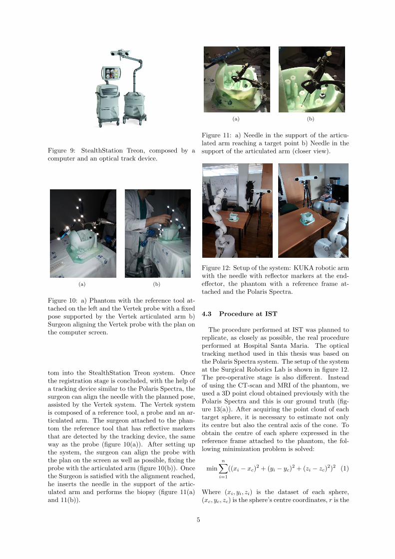
Figure 9: StealthStation Treon, composed by acomputer and an optical track device.
(a) (b)
Figure 10: a) Phantom with the reference tool at-tached on the left and the Vertek probe with a fixedpose supported by the Vertek articulated arm b)Surgeon aligning the Vertek probe with the plan onthe computer screen.
tom into the StealthStation Treon system. Oncethe registration stage is concluded, with the help ofa tracking device similar to the Polaris Spectra, thesurgeon can align the needle with the planned pose,assisted by the Vertek system. The Vertek systemis composed of a reference tool, a probe and an ar-ticulated arm. The surgeon attached to the phan-tom the reference tool that has reflective markersthat are detected by the tracking device, the sameway as the probe (figure 10(a)). After setting upthe system, the surgeon can align the probe withthe plan on the screen as well as possible, fixing theprobe with the articulated arm (figure 10(b)). Oncethe Surgeon is satisfied with the alignment reached,he inserts the needle in the support of the artic-ulated arm and performs the biopsy (figure 11(a)and 11(b)).
(a) (b)
Figure 11: a) Needle in the support of the articu-lated arm reaching a target point b) Needle in thesupport of the articulated arm (closer view).
Figure 12: Setup of the system: KUKA robotic armwith the needle with reflector markers at the end-effector, the phantom with a reference frame at-tached and the Polaris Spectra.
4.3 Procedure at IST
The procedure performed at IST was planned toreplicate, as closely as possible, the real procedureperformed at Hospital Santa Maria. The opticaltracking method used in this thesis was based onthe Polaris Spectra system. The setup of the systemat the Surgical Robotics Lab is shown in figure 12.The pre-operative stage is also different. Insteadof using the CT-scan and MRI of the phantom, weused a 3D point cloud obtained previously with thePolaris Spectra and this is our ground truth (fig-ure 13(a)). After acquiring the point cloud of eachtarget sphere, it is necessary to estimate not onlyits centre but also the central axis of the cone. Toobtain the centre of each sphere expressed in thereference frame attached to the phantom, the fol-lowing minimization problem is solved:
min
n∑i=1
((xi − xc)2 + (yi − yc)
2 + (zi − zc)2)2 (1)
Where (xi, yi, zi) is the dataset of each sphere,(xc, yc, zc) is the sphere’s centre coordinates, r is the
5

(a) (b)
Figure 13: a) Phantom point cloud b) target pointsand desired orientations for all the spheres.
radius of the sphere and n is the size of the dataset.Knowing the centre, it is necessary to estimate thecentral axis of the cone. Our approach begins byisolating the points of the internal curved cone. Todo this we select the points inside a smaller radiussphere with the same centre (figure 14). With thissmaller dataset, dcone, we need to slice the curvedcone in parts and calculate the centroid of each slice.To know in which direction to slice the curved conewe fit a line by Orthogonal Distance Regression.Let c be the mean values of dcone (eq. 2):
c =
[1n
n∑i=1
xi1n
n∑i=1
yi1n
n∑i=1
zi
](2)
Where n is the size of the smaller dataset.Lets defineA as the matrix od dimension n× 3 (eq. 3):
A =
x1 − cx y1 − cy z1 − cz... ... ...
xn − cx yn − cy zn − cz
(3)
Applying the Singular Value Decomposition (SVD)to matrix A, we choose the highest eigenvalue ofmatrix S, whose diagonal entries are the singularvalues of A, and the correspondent eigenvector ofthe matrix V , whose columns are the right-singularvectors of A, to obtain the direction of the axis ofthe cone. Knowing the direction, we slice the coneinto 20 slices along this axis, compute the centroidof each slice. Considering the new dataset the cen-troids of each slice, and by repeating the processexplained before using eq. 2 and eq. 3, a new orien-tation can be computed. This is the direction con-sidered as the true direction of the cone’s centralaxis. Figure 13(b) shows the result for the wholeset. Once the centre coordinates and respective ori-entation vectors are computed, we define the targetpoints for the robotic experiments by a translationwith a magnitude of 7mm along the orientation vec-tor (figure 8(a)).Once the target points and respective orientationsare defined, a reference tool with reflective markerswas attached to the needle’s support on the roboticarm (figure 15 ). With this setup the Polaris Spec-tra can detect both reference tools and relate the
Figure 14: Sphere point cloud - isolation of the in-ternal curved cone.
Figure 15: Reference tool with reflective markersattached to the needle’s support.
Figure 16: Examples of trials.
position of the needle and the position of the phan-tom.Like in the actual procedure performed in HospitalSanta Maria, the registration of the phantom mustbe done to know where the phantom is located inthe workspace of the robotic arm. Once the regis-tration is done, the surgeon just needs to grab theend-effector of the robotic arm and pull it, slowly,to the target point (figure 16). The robot will hap-tically guide the surgeon to the planned pose forthat target.
6

Figure 17: Reference frame of the Polaris Spec-tra (Oxpolypolzpol), needle tip (Oxnynzn), phan-tom (Oxs1ys1zs1), needle holder after the pivoting(Oxs2ys2zs2), and KUKA robotic arm (Oxkykzk)
5 Implementation
5.1 Patient’s registration - localization ofthe target points in robotic arm’s ref-erence frame
In figure 12 the setup of the system used at ISTis represented. In order to perform the biopsy, therobotic arm must know where the target point islocated in its reference’s frame during all the pro-cedure. To detect the position of the phantom, areference tool (s1) of the Polaris Spectra is attachedto it and another reference tool (s2) is attached tothe needle’s support. With this configuration, thePolaris Spectra can detect the pose of the tools s1
and s2 expressed in its reference frame, T pols1 and
T pols2 respectively. From the FRI we know the pose
of the needle’s reference frame in the robotic arm’sreference frame, T kuka
needle. The Polaris Spectra sys-tem allows us to perform a pivoting motion of areference tool about a fixed point. In other words,it allows us to perform a translation of the tool ref-erence frame to the pivoting point. In this case, thereference frame of the reference tool s2 was movedto the tip of the needle as shown in figure 17. Oncethe pivoting is done, the position of the referencetool s2 expressed in reference frame s1 is the sameas the needle’s position expressed in reference frames1. To calculate the pose of reference tool s1 ex-pressed in the robotic arm’s reference frame, T k
s1 ,a rigid body transformation must be formulated.We have two correspondent datasets; the position ofthe needle expressed in the robotic arm’s referenceframe (from FRI), pk
n, and the position of needleexpressed in reference frame s1 (from the Polaris),ps1n , which are related by:
pkn = Rk
s1ps1n + pk
s1 (4)
Where Rks1 is a 3×3 rotation matrix and pk
s1 is a 3×1 position vector of the reference frame s1 expressedin the robotic arm’s reference frame. Defining H as
Figure 18: Illustration of the surgery environment.
the correlation matrix between the two datasets:
H =
n∑i=1
((ps1n )centredi
(pkn)Tcentredi
) (5)
The optimal rotation matrix, Rks1 , is calculated re-
sorting to the singular value decomposition [5]:
SV D(H) = USVT (6)
Rks1 = Udet(UVT )VT (7)
Knowing Rks1 the optimal translation vector, pk
s1 ,between the two datasets is:
pks1 = pk
n −Rks1 p
s1n (8)
Therefore,having the estimated pose the referenceframe s1 attached to the phantom expressed in therobotic arm’s reference frame, Rk
s1 and pks1 ,having
the needle’s pose expressed in the robotic arm’s ref-erence frame, Rk
n and pkn, and having the target
point position and orientation expressed in the ref-erence frame s1 frame from the pre-operative stage,ps1t and ns1
t , it is possible to obtain the target pointposition, pk
t , and orientation vector, nkt , expressed
on the robotic arm’s reference frame:
pkt = Rk
s1ps1t + pk
s1 (9)
nkt = Rk
s1ns1t (10)
5.2 Surgical co-manipulation mode
In this thesis, a co-manipulation mode was devel-oped that allows the surgeon to perform the biopsy.While the surgeon executes the biopsy, the robotwill constrain the surgeons movement to a coneshaped zone, guiding the needle to the desired tar-get point with the desired orientation planned pre-operatively (figure 18). After registration, the fol-lowing variables are known during the surgery:pkt Position of the target point expressed in the
robotic arm’s base reference frame (obtained fromthe patient’s registration)pkn Position of the tip of the needle expressed in the
robotic arm’s base reference frame (obtained fromthe FRI)Rk
n Rotation matrix of the needle’s reference frame
7

Figure 19: Impedance environment referenceframes. Cone’s vertice position, pk
c , target point’sposition, pk
t , and the needle’s position, pkn, with re-
spect to the robotic arm’s base reference frame andthe needle’s position, pc
n, with respect to the cone’sreference
Figure 20: Virtual impedance environment.
expressed in the robotic arms base reference frame(obtained from the FRI)hcone - Height of the virtual impedance cone (de-fined by the user)rmax - Maximum radius of the virtual impedancecone (defined by the user)Based on these variables, was defined the vir-tual environment shown in figure 19. The virtualimpedance environment can be separated in 6 ar-eas (figure 20). The desired behaviour of the robotin each area is:
• Area 1: Gravitational compensation, the usercan move the robot freely
• Area 2: The needle tends to go to the centralaxis of the cone, although not imposing anymovement along that axis. As the user guidesthe needle to the vertice, the orientation of theneedle will be forced to be the desired one.
• Area 3: The user may try to go in the direc-tion of the target point from the area 1, butfrom outside of the cone. In this area, a forcepulling the needle back to area 1 must be ap-plied.
• Area 4: Once inside the cone, the user maytry to leave the cone through its surface and
reach area 4. In this area, a force pulling theneedle back to area 2 must be applied, withoutimposing any movement along the central axisof the cone.
• Area 5: The needle must be aligned withthe desired orientation and tends to go to thecentral axis of the cone without imposing anymovement along that axis. The robot must im-pose a strong constrain in order to prevent theuser to leave the central axis.
• Area 6: Once the needle reaches the targetpoint, a constraint must be imposed to makesure the needle does not go beyond the targetpoint. The only movement allowed is to gobackwards.
6 Results
6.1 Procedure performed at IST
6.1.1 Needle’s calibration
The robotic arm kinematics provides its end-effector position with respect to its base referenceframe. When a tool is attached to the end-effector,it is necessary to calibrate it. The calibrationwas performed with an associated TCP error of0.191mmIn order to understand the precision of the roboticarm, after calibration we performed trajectories ofthe null-space of the arm, with maximum Carte-sian stiffness of the end-effector. We continuouslymeasured the pose of the needle and registered thevariations around the initial point, both via FRIand with the Polaris Spectra. The results obtainedfrom this movement are:
Position’s error Orientation’s errorPolaris Spectra 1.92mm± 0.96mm 2.26◦ ± 0.15◦
KUKA LWR 4+ 1.62mm± 0.8mm 0.54◦ ± 0.24◦
Table 1: Mean errors of the tip obtained by varyingthe null-space.
Once the needle was calibrated for the roboticarm, the calibration for the Polaris Spectra fol-lowed. The optical tracking device detects the ref-erence tool attached to the needle’s support. Thereference frame of the tool must be translated by anoffset to match with the tip of the needle as shownin figure 21. The calibration was performed withan associated error of 0.64mm.
6.1.2 Phantom’s registration
Once the needle is calibrated on the robotic armand on the Polaris Spectra, it is possible to perform
8

Figure 21: Needle’s pivoting on Polaris Spectra.
(a) (b)
Figure 22: a) Desirable points to collect for thephantom’s registration b) PPoints collected duringthe registration with the first hypothesis. Green -points under 1mm error- Red - points above 1mmerror
the phantom’s registration. This step is fundamen-tal because it will highly influence the results sinceit will allow the robotic arm to know where the tar-get point is in its workspace. When collecting pointsfor the registration it is imperative to collects pointsof zones with significant features of the phantom(figure 22(a)). For this thesis two approaches toselect the set of points to perform the registrationwere followed. In the first approach it was decidedto collect points of the same facial areas as chosen atHospital Santa Maria (figure 22(b)), in the secondapproach it was decided to collect points of the coneof one of the spheres. A total of 29266 points werecollected for the first hypothesis and 2141 points forthe second hypothesis.The mean position error forthe 1st hypothesis was 1.127mm±0.332mm and forthe 2nd was 0.236mm± 0.092mm.
6.1.3 Biopsy - IST
Once the calibrations and the phantom’s registra-tion was performed, the biopsies were performed.The target points and desired orientation vectorsexpressed in the reference frame of the phantomwere defined as explain in figure 8(b). The mean po-sition’s error for the 1st hypothesis was 2.61mm ±1.52mm and for the 2nd was 2.46mm ± 1.04mm.The mean orientation’s error for the 1st hypothesiswas 4.34◦±3.30◦ and for the 2nd was 3.61◦±2.75◦.
Figure 23: Procedure to obtain the centres of thetarget spheres from the medical images. The stepsfor the CT images are shown on the left, and thesteps for the MRI are shown on the right.
6.2 Procedure performed at Hospital SantaMaria
6.2.1 Image registration
When analysing the results of the biopsy proce-dure at Hospital Santa Maria, it is necessary to sep-arate the procedure in 2 phases: the preoperativephase and the intraoperative phase. The first stepin the pre-operative phase is to quantify the errorassociated with image acquisition, in other words,how much the MR and the CT-scan distort the realobject. To do this, the images were converted to apoint cloud and the target spheres segmented. Hav-ing only the point cloud that represents the spheres,by optimization as in eq. 1, the target points wereobtained. The scheme of this procedure can be ob-served in figure 23.To compute the orientation vector, matrix A (eq.3) was computed and the SVD decomposition wasapplied.Having the centre of the spheres in each imagemodality, these were registered to each other. Themean position’s error is 0.455mm ± 0.249mm andthe mean orientation’s error is 7.487◦ ± 5.506◦.The second step is to quantify the error betweenthe MRI and the phantom and the error betweenthe CT-scan and the phantom. The errors are pre-sented in table 2.The errors associated to the capacity of the sur-geon to select the desired targets and orientationsare 1.10mm±0.39mm and 5.55◦±2.91◦, for position
9

orientation respectively.
Position’s error Orientation’s errorMRI 1.111mm± 0.324mm 5.863◦ ± 3.030◦
CT-scan 1.202mm± 0.429mm 6.238◦ ± 3.692◦
Table 2: Registration’s error between the medicalimages and the phantom.
6.2.2 Biopsy - Hospital Santa Maria
After the registration, done by the StealthStationTreon, the surgeon performed the biopsies with amean position’s error of 3.74mm± 1.56mm and anorientation’s error of 3.77◦ ± 2.23◦.
7 Conclusions
The presented work focused on developing a com-plete robotic solution that can position a needle ina desired target inside the brain. Using a roboticsystem in this type of surgeries brings advantageswhen compared with the conventional brain surg-eries namely, it is capable of removing the tremorof the human hand, it can achieve a higher levelof accuracy, it allows a decrease of the burr holesize and also decreases the time of the procedure.Another important objective of this work was totest the capabilities of the KUKA LWR 4+ in a co-manipulative surgery. The first phase of this workwas to create an interface with the KUKA LWR4+ in real-time using MATLAB. That interface notonly takes the full advantage of FRI at its highestcommunication frequency, 1kHz, but is also easilyadapted to future works using the robotic arm atthe Surgical Robotics Lab.The ultimate product of this thesis is the roboticsystem developed for brain surgeries. This systemcomprises not only the KUKA LWR 4+ but also theoptical tracking device Polaris Spectra. The devel-oped virtual impedance control solution is a safeand helpful way for the surgeon to guide the robotto the desired target position. The robotic systemdeveloped provides a safe environment to be used insurgery since a security zone was implemented thatstops the robot to enter the no-go zone even if thesurgeon forces it.The robotic solution was tested in a procedure thattried to simulate a brain biopsy. For this, the phan-tom that simulates the human skull was used as apatient. The procedure was performed at HospitalSanta Maria with the current methods used in manyhospitals and then simulated at Surgical RoboticsLab. The brain biopsy simulated consisted in threemain steps, first, the choosing of the desired targetposition and needle trajectory via image processing;second, the registration of the phantom; and third,
the guidance of the needle to the target point.At Hospital Santa Maria, the position’s error of theentire procedure was 3.74mm ± 1.56mm and theorientation’s error was 3.77◦ ± 2.23◦. These resultsare positive because this error carries the error ofmany steps as, for example, the registration’s error.At Surgical Robotics Lab the position’s error of theentire procedure was 2.46mm ± 1.04mm and theorientation’s error was 3.61◦ ± 2.75◦.The three main sources of error that influenced thefinal needle position at Surgical Robotics Lab werethe registration method, the needle’s positioningand the tool calibration.The mean position’s error for the registration pro-cess was of 0.236mm± 0.092mm, which can be ex-plained by displacement of the table and/or thephantom during the procedure. The tool calibra-tion’s error on Polaris Spectra was 0.64mm and thecalibration’s error on the robotic arm was 0.191mm.From these, one can conclude that the main sourceof error is in fact the calibration process.To conclude, the final outcome of this project isan improvement compared with previous works andits positive results constitutes a good foundationfor further development and enhancement of thisrobotic surgical system.
References
[1] T. P. Leon Zlajpah. Fri-xpc server for kuka fricontroller. Technical report, Institut Jozef Ste-fan, 2014.
[2] NDI. Official website of NDI.http://www.ndigital.com/msci/applications/.
[3] P. Pires. Position and Force Control ofLightweight Robot Manipulators for OrthopaedicSurgery. PhD thesis, Instituto Superior Tecnico,2010.
[4] T. Salgueiro. Robot assisted needle interven-tions for brain surgery. Master’s thesis, InstitutoSuperior Tecnico, 2014.
[5] O. Sorkine. Least-squares rigid mo-tion using svd. Technical report, 120.3,https://igl.ethz.ch/projects/ARAP/svd rot.pdf,2009.
[6] K. S. Technology. Kuka system software 5.6 lr- operating and programming instructions forsystem integratiors. Technical report, KUKASystem Technology, 2010.
[7] K. S. Technology. Kuka fast research interface1.0 for kuka system software 5.6 lr. Technicalreport, KUKA System Technology, 2011.
10