Embed Size (px)
Citation preview
educational section
A CHEAP AND EASILY USED PHOTOELASTIC COMPENSATOR
bY
G. L. HILBORNE and K. SHARPLES Birmingham Polytechnic
A simple compensator for photoelastic work not requiring partial fringe determination may be made from urethane rubber (1) which is extremely sensitive to the photoelastic eflect.
The compensator may be used to determine (a) the sign of the stresses at free boundaries; (b) the direction of the algebraic maximum principal
stress (a,) at a point. (c) the fringe orders in two-dimensional models or in
frozen-stress slices, where no zero fringe is present.
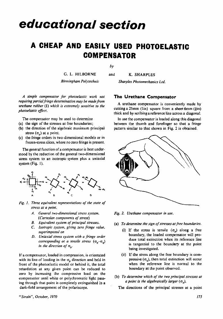
The general function of a compensator is best under- stood by the reduction of the general two-dimensional stress system to an isotropic system plus a uniaxial system (Fig. 1).
A. 8. C D. 4
Fig. 1. Three equivalent representations of the state of stress at a point. A. General two-dimensional stress system.
(Cartesian components of stress) B. Equivalent system of principal stresses. C. Isotropic system, giving zero fringe value,
superimposed on D. Uniaxial stress system with a fringe order
corresponding ot a tensile stress (op-aq) in the direction of 0,.
If a compensator, loaded in compression, is orientated with its line of loading in the ap direction and held in front of the photoelastic model or behind it, the total retardation at any given point can be reduced to zero by increasing the compressive load on the compensator until white or polychromatic light pass- ing through that point is completely extinguished in a dark-field arrangement of the polariscope.
Sharples Photomechanics Ltd.
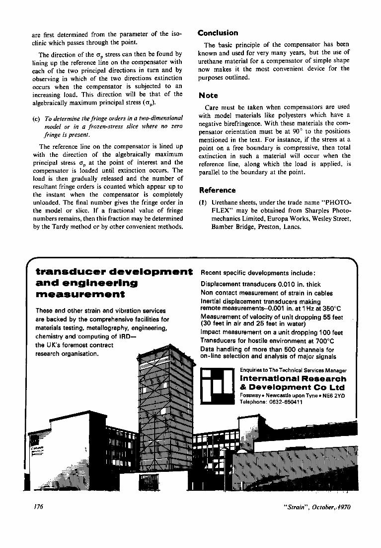
The Urethane Compensator A urethane compensator is conveniently made by
cutting a 25mm (lin) square from a .sheetSmm (*in) thick and by scribing a reference line across a diagonal.
In use the compensator is loaded along this diagonal between the thumb and forefinger so that a fringe pattern similar to that shown in Fig. 2 is obtained.
Fig. 2. Urethane compensator in use.
(a) To determine the sign of stresses at free boundaries. (i) If the stress is tensile (a,) along a free
boundary, the loaded compensator will pro- duce total extinction when its reference line is tangential to the boundary at the point being investigated.
(ii) If the stress along the free boundary is com- pressive (aq), then total extinction will occur when the reference line is normal to the boundary at the point observed.
(b) To determine which of the two principal stresses at
The directions of the principal stresses at a point
a point is the algebraically larger (0,).
“Strain”, October, 1970 175
are first determined from the parameter of the iso- clinic which passes through the point.
The direction of the up stress can then be found by lining up the reference line on the compensator with each of the two principal directions in turn and by observing in which of the two directions extinction occurs when the compensator is subjected to an increasing load. This direction will be that of the algebraically maximum principal stress ( op).
(c) To determine the fringe orders in a two-dimensional model or in a frozen-stress slice where no zero fringe is present.
The reference line on the compensator is lined up with the direction of the algebraically maximum principal stress op at the point of interest and the compensator is loaded until extinction occurs. The load is then gradually released and the number of resultant fringe orders is counted which appear up to the instant when the compensator is completely unloaded. The final number gives the fringe order in the model or slice. If a fractional value of fringe numbers remains, then this fraction may be determined by the Tardy method or by other convenient methods.
Conclusion
The basic principle of the compensator has been known and used for very many years, but the use of urethane material for a compensator of simple shape now makes it the most convenient device for the purposes outlined.
Note Care must be taken when compensators are used
with model materials like polyesters which have a negative birefringence. With these materials the com- pensator orientation must be at 90” to the positions mentioned in the text. For instance, if the stress at a point on a free boundary is compressive, then total extinction in such a material will occur when the reference line, along which the load is applied, is parallel to the boundary at the point.
Reference
(1) Urethane sheets, under the trade name “PHOTO- FLEX” may be obtained from Sharples Photo- mechanics Limited, Europa Works, Wesley Street, Bamber Bridge, Preston, Lancs.
transducer development Recent specific developments include:
and engineering Displacement transducers 0.01 0 in. thick
measurement Non contact measurement of strain in cables Inertial displacement transducers making remote measurements-0.001 in. at 1 Hz at 350°C These and other strain and vibration services Measurement of velocity of unit dropping 55 feet (30 feet in air and 25 feet in water)
are backed by the comprehensive facilities for materials testing, metallography, engineering,
Impact measurement on a unit dropping 100 feet Transducers for hostile environment at 700°C chemistry and’computing of IRD-
Data handling of more than 500 channels for on-line selection and analysis of major signals
the U K s foremost contract . .
Enquiries to The Technical Services Manager
International Research & Development Co Ltd Fossway Newcastle upon Tyne NE6 2YD
I Telephone: 0632-65041 1
176 “Strain”, October,, M70