Embed Size (px)
Citation preview
A CFD AnAlysis on the eFFeCt oF Vortex FinDer AnD CylinDriCAl length on CyClone hyDroDynAmiCs
AnD CentriFugAl ForCes
luqman Chuah A.1, Jolius gimbun2, thomas s. y. Choong1 and A. Fakhru’l-razi1
1Department of Chemical and Environmental Engineering, Faculty of Engineering,Universiti Putra Malaysia, 43400 UPM, Serdang, Selangor Darul Ehsan.
2Faculty of Chemical and Natural Resources Engineering, University Collage of Engineering and Technology Malaysia,
KUKTEM, Locked Bag 12, 25000 Kuantan, Pahang Darul Makmur.E-mail: [email protected]/ [email protected]
abstractThe article presents a Computational Fluid Dynamics (CFD) calculation to predict and to evaluate the flow field and centrifugal forces of gas cyclones. The numerical solutions were carried out using commercial CFD code FLUENT 6.0. The problem of modelling highly swirling flow is overcame by means of an algebraic turbulence model, and all the features of the experimentally observed gas flow in a cyclone are shown to be computationally reproduced. It was found that CFD simulations predict excellently the axial and tangential velocity with an average deviation of ± 0.5 m/s from the presented experimental data. The physical mechanism for prolonged cyclone cylindrical body and vortex finder has also been successfully elucidated. Specifically, results obtained from the computer modelling exercise have demonstrated that CFD with RSM turbulence model is suitable for modelling a flow field and hydrodynamic of cyclone.
Keywords: Centrifugal Force, CFD, Cyclones, Cylindrical Height, Hydrodynamics, Vortex Finder
1.0 introDuCtionCyclones used in many technical applications [1], such as
physical separation processes (especially dust from a gas stream) and chemical reactions (combustion of solid low calorific value fuels). In spite of the wide use and simple geometry, the real working principles of a cyclone chamber are far from being fully understood, mainly owing to the extreme complexity of the swirling turbulent flow field inside the device [2]. The gas stream enters the cyclone tangentially and force by its geometry into a vortex motion in the cylindrical section, spiralling downwards until the conical section is reached. In this part of the device, the centrifugal forces can be several times greater than gravity, contributing to particle separation. Then, the gas flow is deflected upwards and outflows from the exhaust duct (also called vortex finder), maintaining the swirling motion. The complexity of the flow pattern inside the chamber is due to the high turbulence level, strong anisotropy, three-dimensionality (3-D) and possible non stationary features typical of highly swirling motions, so that both experimental analysis and numerical simulations become notably difficult. Probably, this is the cause that basic cyclone design has evolved very little from the first applications.
Analytical solutions for the gas motion have been reported in the past [3, 4], but, due to the approximations introduced, their results are only valid in delineating the main features of
the vortex flow. Numerical solutions have been also developed [5, 6], but they are strongly dependent on the turbulence model used and satisfactory agreement with experimental data has been achieved using the second-order Reynolds-stress model (RSM) as closure assumption for the turbulence modelling in a general purpose finite volume code [7, 8, 9]. Early experimental investigators of the cyclone chamber behaviour used Pitot tubes [10] and hot-wire anemometry [11]. They aimed first at determining the most efficient shape of a cyclone and then at understanding the turbulent flow structure, but the two techniques have several drawbacks and the reliability of their results cannot be guaranteed. Detailed measurements of the gas flow in a cyclone became possible only recently with the availability of Laser Doppler Velocimetry (LDV) and revealed a very complex structure with 3-D time dependent instabilities originated by the strongly swirling flow [12].
The present study was thus undertaken in an effort to carry out a modelling and simulation on the gas flow field within the whole body of a laboratory scale cyclone from the inlet chamber to the exhaust duct. In this study, the CFD calculations are carried out using commercial finite volume code FLUENT 6.0 while the centrifugal forces calculation are performed in the MS Excel spreadsheet. The CFD prediction is compared with the presented experimental data obtained from the literature. An attempt was
(Date received: 4.2.2008)
Journal - The Institution of Engineers, Malaysia (Vol. 71, No.2, June 2009) 51
luqmAn ChuAh A., et al.
Journal - The Institution of Engineers, Malaysia (Vol. 71, No.2, June 2009)52
also made to evaluate the flow field of cyclones with the different vortex finder length and cylindrical body height.
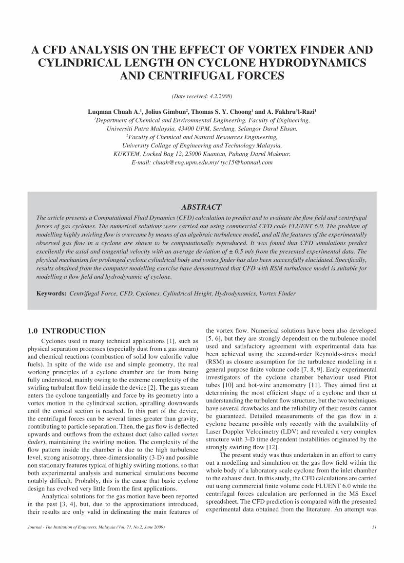
2.1 CFDThe numerical calculation was made with a fine numerical
grid as shown in Figure 1. The numerical grid contains 38432 nodes to yield a reasonable prediction. The CFD simulation was performed with a Pentium IV 2.8 GHz HP workstation XW8000 with 512 cache-memory, 1 GB RAM-memory, and 110 GB hard-disc memory. The geometrical dimensions and configuration of these cyclones are given in Table 1 and Figure 2, respectively.
table 1: Geometrical dimensions of cyclones studied
Geometry(cm)
a b De S h H B D
Stairmand cyclone
9.5 3.8 6.4 9.5 28.5 76 7.25 19
The finite volume methods have been used to discretised the partial differential equations of the model using the SIMPLE method for pressure-velocity coupling and the Quick scheme to interpolate the variables on the surface of the control volume. The RSM turbulence model was used in this model due to the anisotropic nature of the turbulence in cyclones. Standard Fluent wall functions were applied and high order discretisation schemes were also used. A velocity inlet boundary was used to specify an air inflow of 7.6 m/s. The simulations were carried out with a zero underflow component. The underflow was therefore represented using a wall boundary. An outflow boundary condition was used to represent the cyclone overflow. A detailed description of the CFD modelling and simulation are presented in previous papers on the prediction of cyclone performance under various operating condition [8, 9].
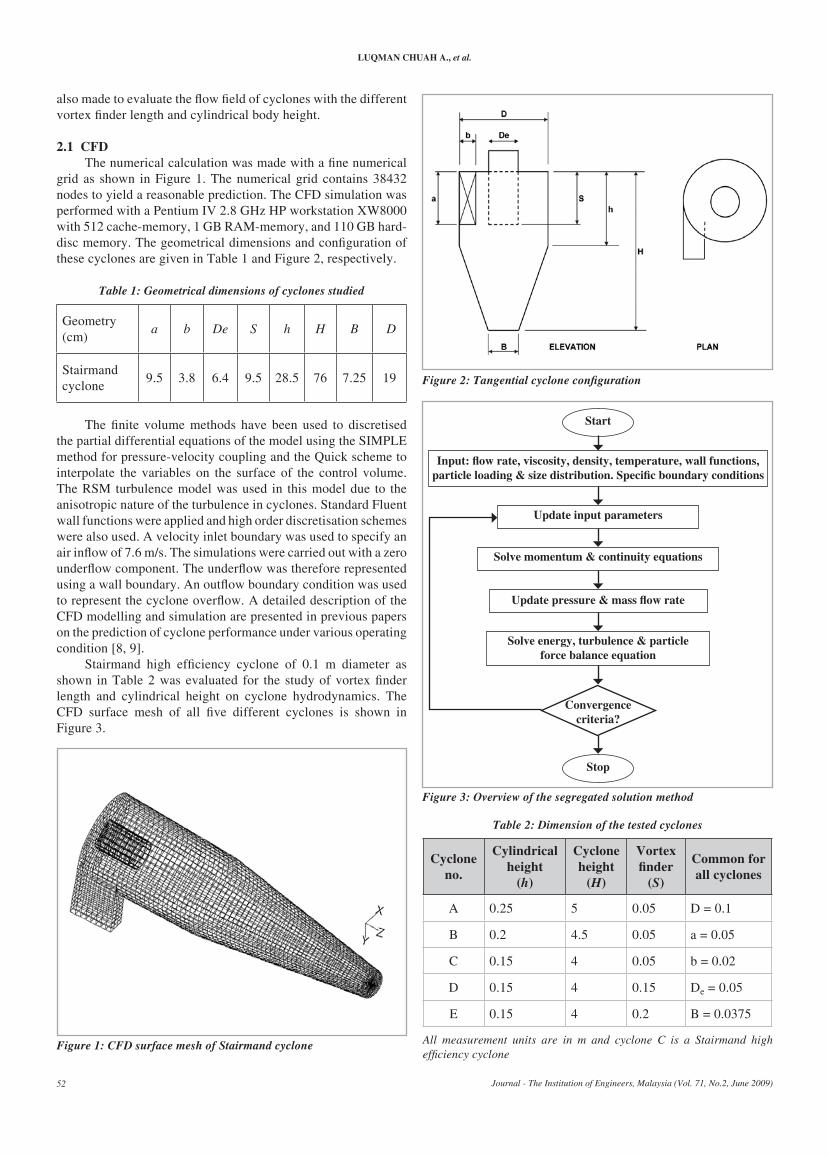
Stairmand high efficiency cyclone of 0.1 m diameter as shown in Table 2 was evaluated for the study of vortex finder length and cylindrical height on cyclone hydrodynamics. The CFD surface mesh of all five different cyclones is shown in Figure 3.
table 2: Dimension of the tested cyclones
Cyclone no.
Cylindrical height
(h)
Cyclone height
(H)
Vortex finder
(s)
Common for all cyclones
A 0.25 5 0.05 D = 0.1
B 0.2 4.5 0.05 a = 0.05
C 0.15 4 0.05 b = 0.02
D 0.15 4 0.15 De = 0.05
E 0.15 4 0.2 B = 0.0375
All measurement units are in m and cyclone C is a Stairmand high efficiency cyclone
Figure 1: cFD surface mesh of stairmand cyclone
Figure 2: Tangential cyclone configuration
Figure 3: Overview of the segregated solution method
start
Input: flow rate, viscosity, density, temperature, wall functions, particle loading & size distribution. Specific boundary conditions
update input parameters
Solve momentum & continuity equations
Update pressure & mass flow rate
Solve energy, turbulence & particle force balance equation
Convergencecriteria?
stop
A CFD AnAlysis on the eFFeCt oF Vortex FinDer AnD CylinDriCAl length on CyClone hyDroDynAmiCs AnD CentriFugAl ForCes
Journal - The Institution of Engineers, Malaysia (Vol. 71, No.2, June 2009) 53
2.2 goVerning equAtions
The governing equation for the turbulent, steady, isothermal and incompressible fluid flow in a cyclone is given by the Navier-Stokes equation as given below:
ρ = 0 (continuity equation) (1)
ρ = – + div(grad u)
+ Sx (momentum equation) (2)
The trajectory of a particle is obtained by integrating the force balance on the particle. This force balance equates the particle inertia with the force acting on the particle, and is given by (for the x-direction in Cartesian coordinates) as:
= FD (u – up) + gx + Fx (3)
FD = • (4)
Re is the relative Reynolds number, which is defined as:
Re = (5)
The values of CD may be taken from standard sources.
2.3 Centrifugal Force
Centrifugal forces play an important role for particle separation in cyclone. Centrifugal force is usually shown as a pseudo force that is resulted from the body’s inertia carrying it straight while some other force makes it move in a curved path. If the particle move in a circular path with radius r and velocity v
c along the path, then it has angular velocity,
ω = (6)
and, Centrifugal force, F
c = = ωw2r (7)
For analysis of cyclone the centrifugal force is commonly expressed as a ratio of gravity force,
Centrifugal force =
Fc =
=
(3)
Gravity force Fg mg g
3.0 result AnD DisCussions3.1 Prediction of cyclone hydrodynamics
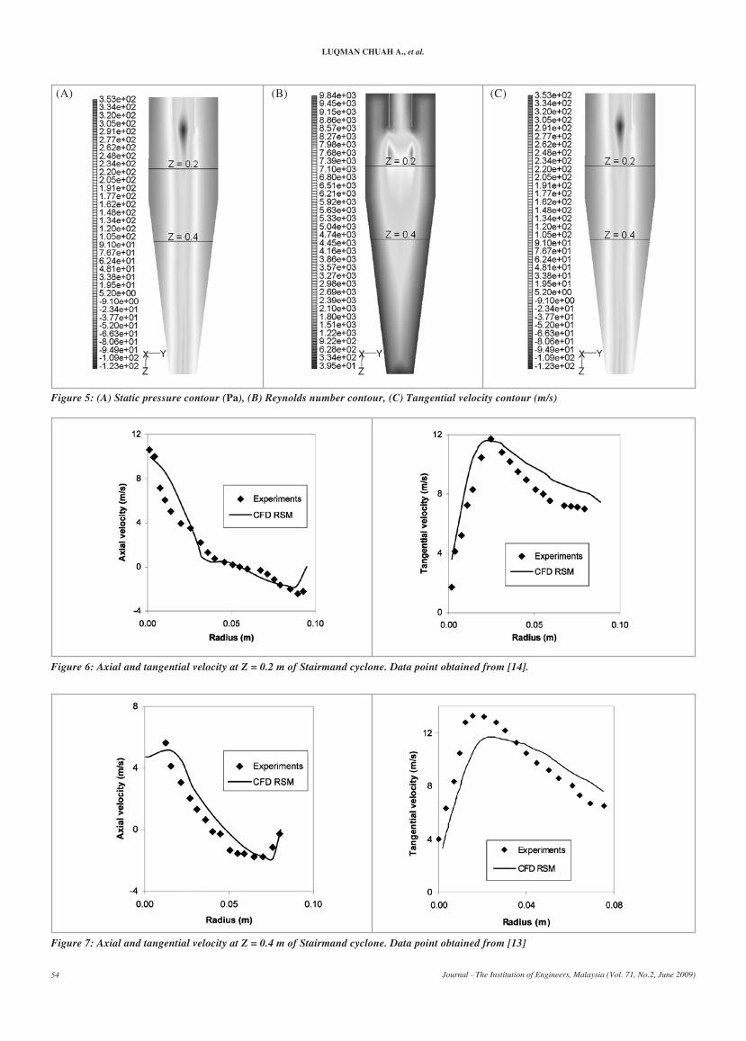
Fraser et al. [14] have carried out a measurement on tangential and axial velocity of a standard Stairmand cyclone using a Laser Doppler Anemometry (LDA) system. LDA has been proven to be a useful tool to study the swirling flow pattern in centrifugal dedusting devices without having to insert probes, which may disturb the swirl [15]. Direct CFD plot of static pressure, Reynolds number and tangential velocity contour are shown in Figures 5. The low-pressure centre in Figure 5A can be responsible for the flow reversion and deviation of the axial velocity peak to the wall of the vortex finder pipe as shown in Figures 6 and 7. The strongest inward velocity found just under the vortex finder wall (Figure 5B) which was represented by a higher Reynolds number (as referred to Equation 5). Those findings agree with an earlier work of Peng et al. [14] on the similar cyclone type. The tangential velocity contours in Figure 4C also agree with the theory that tangential velocity must be zero on the axis of rotation. The comparison between LDA result and CFD simulation are shown in Figures 6 and 7. CFD with RSM turbulence model predict the cyclone axial and tangential velocity well with an average deviation of ±0.5 m/s from the Fraser’s experiment. It can be concluded that CFD prediction has high accuracy in simulating the flow field in cyclone.V
r
r
∂ui
∂t
dup
dt
∂ui
∂t
ρp – ρρp
∂P∂x
2c
mvr
18µρpd
2p
ρdp|up – u|µ
CDRe24
2cmv
r
(A) (B) (C) (D) (E)
Figure 4: CFD surface mesh of the cyclone of different cylindrical height (A to C), and vortex finder length (C to E)
2cv
r
luqmAn ChuAh A., et al.
Journal - The Institution of Engineers, Malaysia (Vol. 71, No.2, June 2009)54
(A) (B) (C)
Figure 5: (a) static pressure contour (Pa), (b) reynolds number contour, (c) tangential velocity contour (m/s)
Figure 6: axial and tangential velocity at Z = 0.2 m of stairmand cyclone. Data point obtained from [14].
Figure 7: axial and tangential velocity at Z = 0.4 m of stairmand cyclone. Data point obtained from [13]
A CFD AnAlysis on the eFFeCt oF Vortex FinDer AnD CylinDriCAl length on CyClone hyDroDynAmiCs AnD CentriFugAl ForCes
Journal - The Institution of Engineers, Malaysia (Vol. 71, No.2, June 2009) 55
A ratio of centrifugal to gravity force analysis on various height of the cyclone has been carried out to evaluate the pattern of centrifugal force inside the cyclone body. The numerical calculations were performed via MS Excel spreadsheet using a tangential velocity obtained from CFD simulations. The comparison of the centrifugal force at two different height of Staimand cyclone is shown in Figure 8.
It was found that the resultant centrifugal force at various height of cyclone is not much different except at the tangential velocity peak. From Figures 6 and 7, the tangential velocity profiles for both heights (Z = 0.2m and Z = 0.4m) are similar, indicating the similar centrifugal force profiles exist along the radius. Figure 8 showed that the centrifugal force decreases with the increase of cyclone radius (Figure 7) and therefore led to a sharper separation as revealed by Coker [15]. Therefore, a cyclone with a smaller body diameter tends to have sharper separation efficiency.
Figure 8: calculated centrifugal to gravity force ratio on a different height of stairmand cyclone
3.2 Evaluation on cylindrical height
Zhu and Lee [16] observed that cyclone collection efficiency decreases as the ratio h/D increases. The mechanism behind
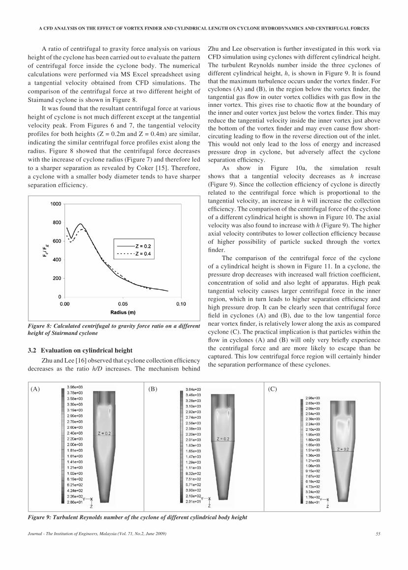
Zhu and Lee observation is further investigated in this work via CFD simulation using cyclones with different cylindrical height. The turbulent Reynolds number inside the three cyclones of different cylindrical height, h, is shown in Figure 9. It is found that the maximum turbulence occurs under the vortex finder. For cyclones (A) and (B), in the region below the vortex finder, the tangential gas flow in outer vortex collidies with gas flow in the inner vortex. This gives rise to chaotic flow at the boundary of the inner and outer vortex just below the vortex finder. This may reduce the tangential velocity inside the inner vortex just above the bottom of the vortex finder and may even cause flow short-circuting leading to flow in the reverse direction out of the inlet. This would not only lead to the loss of energy and increased pressure drop in cyclone, but adversely affect the cyclone separation efficiency.
As show in Figure 10a, the simulation result shows that a tangential velocity decreases as h increase (Figure 9). Since the collection efficiency of cyclone is directly related to the centrifugal force which is proportional to the tangential velocity, an increase in h will increase the collection efficiency. The comparison of the centrifugal force of the cyclone of a different cylindrical height is shown in Figure 10. The axial velocity was also found to increase with h (Figure 9). The higher axial velocity contributes to lower collection efficiency because of higher possibility of particle sucked through the vortex finder.
The comparison of the centrifugal force of the cyclone of a cylindrical height is shown in Figure 11. In a cyclone, the pressure drop decreases with increased wall friction coefficient, concentration of solid and also leght of apparatus. High peak tangential velocity causes larger centrifugal force in the inner region, which in turn leads to higher separation efficiency and high pressure drop. It can be clearly seen that centrifugal force field in cyclones (A) and (B), due to the low tangential force near vortex finder, is relatively lower along the axis as compared cyclone (C). The practical implication is that particles within the flow in cyclones (A) and (B) will only very briefly experience the centrifugal force and are more likely to escape than be captured. This low centrifugal force region will certainly hinder the separation performance of these cyclones.
(A) (B) (C)
Figure 9: turbulent reynolds number of the cyclone of different cylindrical body height
luqmAn ChuAh A., et al.
Journal - The Institution of Engineers, Malaysia (Vol. 71, No.2, June 2009)56
Figure 11: centrifugal force at Z = 0.2 m of cyclone of a different cylindrical body height
3.3 eVAluAtion on Vortex FinDerThe vortex finder size is an especially important dimension,
which significantly affects the cyclone performance as its size plays a critical role in defining the flow field inside the cyclone, including the pattern of the outer and inner spiral flows. Kim and Lee [17] described how the ratio of the diameters of cyclone body (D) and the vortex finder (D
e) affected the collection
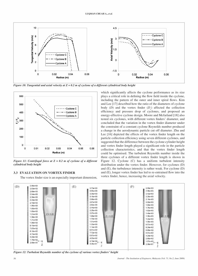
efficiency and pressure drop of cyclones, and proposed an energy-effective cyclone design. Moore and Mcfarland [18] also tested six cyclones, with different vortex finders’ diameter, and concluded that the variation in the vortex finder diameter under the constraint of a constant cyclone Reynolds number produced a change in the aerodynamic particle cut off diameter. Zhu and Lee [16] depicted the effects of the vortex finder length on the particle collection efficiency using seven different cyclones, and suggested that the difference between the cyclone cylinder height and vortex finder length played a significant role in the particle collection characteristics, and that the vortex finder length could be optimised. The turbulent Reynolds number inside the three cyclones of a different vortex finder length is shown in Figure 12. Cyclone (C) has a uniform turbulent intensity distribution under the vortex finder. However, for cyclones (D) and (E), the turbulence intensity is rather weak. For cyclone (D) and (E), longer vortex finder has led to re-entrained flow into the vortex finder, hence, increasing the axial velocity.
(D) (E) (F)
Figure 12: Turbulent Reynolds number of the cyclone of various vortex finders’ height
Figure 10: tangential and axial velocity at Z = 0.2 m of cyclone of a different cylindrical body height
A CFD AnAlysis on the eFFeCt oF Vortex FinDer AnD CylinDriCAl length on CyClone hyDroDynAmiCs AnD CentriFugAl ForCes
Journal - The Institution of Engineers, Malaysia (Vol. 71, No.2, June 2009) 57
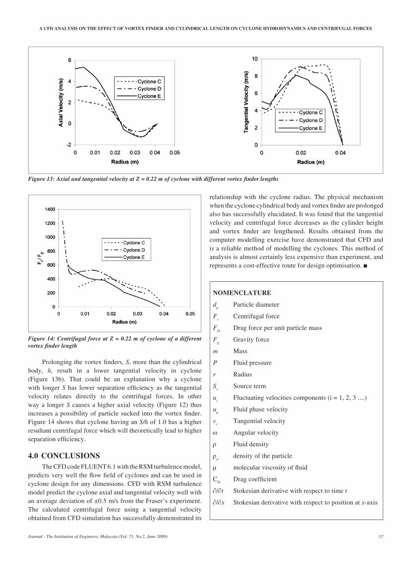
Figure 14: centrifugal force at Z = 0.22 m of cyclone of a different vortex finder length
Prolonging the vortex finders, S, more than the cylindrical body, h, result in a lower tangential velocity in cyclone (Figure 13b). That could be an explanation why a cyclone with longer S has lower separation efficiency as the tangential velocity relates directly to the centrifugal forces. In other way a longer S causes a higher axial velocity (Figure 12) thus increases a possibility of particle sucked into the vortex finder. Figure 14 shows that cyclone having an S/h of 1.0 has a higher resultant centrifugal force which will theoretically lead to higher separation efficiency.
4.0 ConClusionsThe CFD code FLUENT 6.1 with the RSM turbulence model,
predicts very well the flow field of cyclones and can be used in cyclone design for any dimensions. CFD with RSM turbulence model predict the cyclone axial and tangential velocity well with an average deviation of ±0.5 m/s from the Fraser’s experiment. The calculated centrifugal force using a tangential velocity obtained from CFD simulation has successfully demonstrated its
relationship with the cyclone radius. The physical mechanism when the cyclone cylindrical body and vortex finder are prolonged also has successfully elucidated. It was found that the tangential velocity and centrifugal force decreases as the cylinder height and vortex finder are lengthened. Results obtained from the computer modelling exercise have demonstrated that CFD and is a reliable method of modelling the cyclones. This method of analysis is almost certainly less expensive than experiment, and represents a cost-effective route for design optimisation.
nomenClAture
dp Particle diameter
Fc Centrifugal force
FD Drag force per unit particle mass
Fg Gravity force
m Mass
P Fluid pressure
r Radius
Sx Source term
ui Fluctuating velocities components (i = 1, 2, 3 ....)
up Fluid phase velocity
vc Tangential velocity
ω Angular velocity
ρ Fluid density
ρp density of the particle
µ molecular viscosity of fluid
CD Drag coefficient
∂/∂t Stokesian derivative with respect to time t
∂/∂x Stokesian derivative with respect to position at x-axis
Figure 13: Axial and tangential velocity at Z = 0.22 m of cyclone with different vortex finder lengths
luqmAn ChuAh A., et al.
Journal - The Institution of Engineers, Malaysia (Vol. 71, No.2, June 2009)58
reFerenCes
[1] A. K. Gupta, D. G. Lilley and N. Syred, Swirl Flows, Abacus Press, Tunbridge Wells, 1984.
[2] G. Solero and A. Coghe, Experimental fluid dynamic characterisation of a cyclone chamber, Experimental Thermal and Fluid Science, 27 (2002) pp. 87-96.
[3] C. C. Hwang, H. Q. Shen, G. Zhu and M. M. Khonsary, On the main flow pattern in hydrocyclones, J. Fluids Eng., 115 (1983) pp. 21–25.
[4] L. X. Zhou and S. L. Soo, Gas–solid flow and collection of solids in a cyclone separator, Powder Technol., 63 (1990) pp. 45–53.
[5] F. Boysan, W. H. Ayers and J. Swithenbank, A fundamental mathematical modelling approach to cyclone design, Trans. IChemE, 60 (1982) pp. 222–230.
[6] S. Nieh and J. Zhang, Simulation of the strongly swirling aerodynamic field in a vortex combustor, J. Fluids Eng., 114 (1992) pp. 367–374.
[7] E. D. Cristea, A. Coghe, G. Solero, P. Conti, 3-D numerical computation and validation of high solid loading flow inside a gas cyclone separator, in Proceedings of the 1998 ASME Fluids Engineering Summer Meeting, Washington, DC, 1998.
[8] J. Gimbun, T. G. Chuah, A. Fakhru’l-Razi and Thomas S. Y. Choong, The influence of temperature and inlet velocity on cyclone pressure drop: a CFD study, Chem. Eng. Process., 44 (2005) pp. 7-12.
[9] J. Gimbun, Thomas S. Y. Choong, T. G. Chuah, A. Fakhru’l-Razi, A CFD study on the prediction of cyclone collection efficiency, Int. Journal of Computational Engineering Science, (2004) (in press).
[10] A. J. Linden, Investigations into cyclone dust collectors, Proc. Inst. Mech. Eng., 130 (1949) pp. 233–251.
[11] B. P. Ustimenko and M.A. Bukhman, Turbulent flow structure in a cyclone chamber, Teploenergetika, 15 (1968) 64–67.
[12] T. O’Doherty, R. Jaryczewski, C. J. Bates, N. Syred, Velocity characteristics of cyclone combustors, Vol. 1: Laser Anemometry, ASME, 1991.
[13] G. E. Klinzing R.D. Marcus, F. Rizk and Leung, Pneumatic Conveying of Solid, 2nd ed., Chapman and Hall, new York, 1997.
[14] S. M. Fraser, A. M. Abdel Rasek and M. Z. Abdullah, (1997) Computational and experimental investigation in a cyclone dust separator, Proc. Instn. Mech. Engrs., 211 (Part E) (1997) pp. 247-257.
[15] W. Peng, A. C. Hoffmann, P. J. A. J. Boot, A. Udding, H. W. A. Dries, A. Ekker and J. Kater, Flow pattern in reverse-flow centrifugal separators, Powder Technol., 127 (2002) pp. 212-222.
[16] A. K. Coker, Understand cyclone design, Chem. Eng. Progr., 28 (1993) pp. 51–55.
[17] Y. Zhu and K. W. Lee, Experimental study on small cyclones operating at high flowrates, J. Aerosol Sci., 30 (1999) pp. 1303–1315.
[18] J. C. Kim and K. W. Lee (1990) Experimental study of particle collection by small cyclones, Aerosol Science and Technology, 12 (1990) pp. 1003–1015.
[19] M. E. Moore and A. R. Mcfarland, (1993) Performance modeling single-inlet aerosol sampling cyclone, Environmental Science and Technology, 27 (1993) pp. 1842–1848.