Embed Size (px)
Citation preview

A Case Study on Using a Nacelle Lidar for Power Performance Testing in Complex Terrain Megan Quick
December 11, 2013

Introduction
• Can a nacelle lidar be used for site calibration?
• Can nacelle lidar be used for power performance testing in complex terrain?
• Previous investigation for uses in simple terrain was done by DTU
• New draft standard includes provisions for ground based lidar
• Case study of available data
• Opportunistic approach at existing test site
2
Nacelle Lidar – Avent Wind Iris
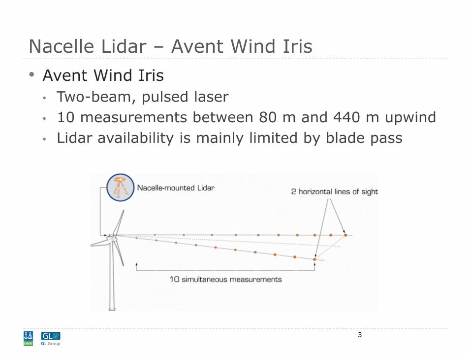
• Avent Wind Iris
• Two-beam, pulsed laser
• 10 measurements between 80 m and 440 m upwind
• Lidar availability is mainly limited by blade pass
3
Site Layout
4
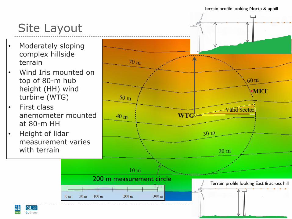
• Moderately sloping complex hillside terrain
• Wind Iris mounted on top of 80-m hub height (HH) wind turbine (WTG)
• First class anemometer mounted at 80-m HH
• Height of lidar measurement varies with terrain
Terrain profile looking North & uphill
200 m measurement circle Terrain profile looking East & across hill

Wind Iris Wind Speed (WS) and Turbulence Intensity (TI) Measurements
• Original scalar lidar output: poor agreement with met mast
• Post processed vector lidar output: lidar WS & TI have better agreement
5

Verification
• Verified as per Annex L of Draft IEC 12-1 Ed.2
• Wind speed is binned per 0.5 m/s wind speed bins
• Deviation = (𝑉𝑀𝑒𝑡 − 𝑉𝐿𝑖𝑑𝑎𝑟)/𝑉𝑀𝑒𝑡
• Deviations should be < 1%
• Deviations are large for WS < 7 m/s
• Blades block measurement
• Filters to adjust:
• Availability
• Rotor RPM
• Filters improve correlation
6
Filters: turbine ON, no curtailment, lidar availability > 20%, valid sector 80°- 90°

Verification with Elevation Difference
• Removed data with low rotor RPM
• Only used data with lidar facing uphill
• Met wind speed 2.5% higher than lidar
• Indicates the decreased measurement height
7
Filters: turbine ON, no curtailment, lidar availability > 20%, valid sector 30°- 60°

Site Calibration • Can site calibration be replaced by a nacelle lidar?
• Calculated lidar-based site calibration correction factors
• Met with 𝑆𝐶𝐼𝐸𝐶 𝑀𝑒𝑡
• Met with 𝑆𝐶𝑙𝑖𝑑𝑎𝑟
• Does not consider wind evolution between 80 m upwind and the turbine rotor
• WTG must be OFF
𝑆𝐶𝑙𝑖𝑑𝑎𝑟 =𝑙𝑖𝑑𝑎𝑟80
𝑙𝑖𝑑𝑎𝑟200
𝑆𝐶𝐼𝐸𝐶𝑚𝑒𝑡 =𝑀𝑒𝑡𝑡𝑢𝑟
𝑀𝑒𝑡𝑟𝑒𝑓
𝑙𝑖𝑑𝑎𝑟200 𝑙𝑖𝑑𝑎𝑟80
𝑀𝑒𝑡𝑡𝑢𝑟 𝑀𝑒𝑡𝑟𝑒𝑓
Proposed
lidar site cal
IEC met
site cal
8

Results – Correction Factors – Flat Sector
• Lidar correction factor
• Limited data due to WTG Availability
• Site Calibration without turbine mast
• 𝑆𝐶𝐼𝐸𝐶𝑚𝑒𝑡 - 𝑆𝐶𝑙𝑖𝑑𝑎𝑟 < 0.1 m/s across WS range
9
IEC Compliant Site Calibration
Lidar 200 m – 80m Site Calibration

Results – Correction Factors –Power Curve
• Well within the uncertainty for each measurement.
10
Power Curves with Corrections – 80°-90° sector
• Lidar only used to develop the correction factor
• Applied to Met Wind speed
• 8 m/s Rayleigh distribution annual energy production (AEP) lidar site calibration is 0.56% lower than AEP
Filters: turbine ON, no curtailment, lidar availability > 20%, valid sector 80°- 90°

Results – Correction Factors- 60°-90° Sector
10° Sector
Center (°)
Measurement
Height (m)
𝑆𝐶𝐼𝐸𝐶𝑚𝑒𝑡 - 𝑆𝐶𝑙𝑖𝑑𝑎𝑟
4m/s (m/s) 8m/s (m/s) 12m/s (m/s)
65 70 0.21 0.11 0.01
75 75 -0.04 -0.03 -0.02
85 80 -0.02 -0.04 -0.05
WTG
North & Uphill
• Site calibration factors for 3 sectors
• Two flattest sectors match IEC site calibration
• 65° sector has significant deviation from IEC site calibration
• Low data counts introduces extra uncertainty
11

Results – Correction Factors – Power Curve
• With a 8 m/s Rayleigh distribution AEP is 0.6% higher with the site calibration factors calculated from the Lidar
• Well within the uncertainty for each measurement.
• AEP difference between only using the 80°-90° sector and 60°-90° is about 1%
12
Power Curves with Corrections 60°-90°
Filters: turbine ON, no curtailment, lidar availability > 20%, valid sector 60°- 90°

Results – Power Curves
• Three scenarios for comparison
• IEC Compliant Test with met mast and site calibration
• Nacelle Anemometer comparison without any adjustment
• 200m Lidar with lidar correction factor applied calibration
13
• The difference in %AEP for an 8 m/s Rayleigh wind distribution is:
• (AEPIEC – AEPLidar200
)/ AEPIEC = 0.1%
• (AEPIEC – AEPNacAne
)/ AEPIEC = 0.1%
Filters: turbine ON, no curtailment, lidar availability > 20%, valid sector 60°- 90°

Conclusions
• Results are encouraging and nacelle lidar may have uses in complex terrain
• Not yet suitable to replace IEC compliant site calibration and power curve measurements – but promising for locations with little elevation change within 2D
• Upcoming IEC-61400-12-1 update only includes ground-based lidar – operational assessment
• Further studies at other sites are needed to prove the results
• Additional shear measurement points would allow for REWS evaluation
• Results Summary:
• Updated vector calculation shows better correlation with met mast
• Verification shows good correlation at high wind speeds and filters were found that correlate at low wind
• Calibration factors with Lidar and IEC method were similar
• Resulting power curves were very similar
• No significant conclusions could be made due to lack of data
• Different measurement methods were compared significant differences were seen in the power curves but the AEP results were similar. Favorable AEP results may be due to the flat terrain
14

Question Slide Place holder
When will lidar overtake met masts for power performance testing?
A. 5 years
B. 10 years
C. Never
15

Thank you!
• References: • Wagner, R: Courtney, M; Gottschall, Antoniou, I; Møller, R; Pederson, Sm; Velociter, T; Bardon, M;
Le, N; Mouritzen, AS; 2012 “Power performance measurement using a nacelle lidar”
16
![CHAPTER 18 Power curves for wind turbines · Electrotechnical Commission (IEC) set the international standard IEC 61400-12 and its revised version IEC 61400-12-1 in 2005 [ 3 ]. These](https://img.pdfslide.us/doc/110x75/6131b7461ecc51586944e92b/chapter-18-power-curves-for-wind-turbines-electrotechnical-commission-iec-set.jpg)