Embed Size (px)
Citation preview
Slope Stability 2013 – P.M. Dight (ed) © 2013 Australian Centre for Geomechanics, Perth, ISBN 978-0-9870937-5-2
Slope Stability 2013, Brisbane, Australia 1
M. Rougier Golder Associates Ltd., Canada
L. Castro Golder Associates Ltd., Canada
D. Birchall Barrick Gold, Canada
Precedent experience is that deep open pit slopes in strong, tight rock masses with high groundwater pressure will not exhibit rock mass failure. The phenomenon is not disputed. It is noted that simple limit equilibrium or finite element slope stability models, often relied upon in mine design and feasibility assessment, can indicate the contrary for high groundwater pressure conditions. In part this is because case history examples on actual groundwater pressure information from this type of open pit are limited. Consequently, over-conservative groundwater conditions can on occasion been assumed for stability analysis purposes.
This paper presents a case study of the results of actual measurements of pore water pressure during pit development using vibrating wire piezometers. They were taken for the purpose of addressing risk management concerns over non-conservative stability analysis results for pit deepening and expansion of the Williams open pit at Barrick Gold's Hemlo Operations. The property is situated on the north shore of Lake Superior near Marathon, Ontario, Canada, in an area of moderate hydraulic recharge.
The actual drawdown cone was found to be tight to the pit shell at depth, yet broader than expected near−surface. This may have been due to structural features and the interpreted effect of blast damage or the combination of slow excavation and moderate recharge. Site-specific observations are presented in terms of their implications for future slope design at Hemlo and in terms of the groundwater aspect of slope stability modelling in tight rock in general, particularly where limited information is available.
This case study paper documents how rock slope pore pressure measurements around an operating open pit in strong, tight rock, helped resolve uncertainties on actual achieved slope depressurisation, at the Hemlo C-pit.
The drawdown cone findings can be used as a reference or precedent example for reasonable preliminary or initial assumptions about possible groundwater conditions and degree of actual slope depressurisation. In particular these findings could be used by practitioners with similar engineering geology settings where estimates of tight rock pore pressures are required.
In many hard rock open pits where no quantitative data is available on slope pore pressures, a geotechnical engineer must interpret the slope hydrogeology based on the regional geology, visual observations, review of sump data and on engineering judgement.
https://papers.acg.uwa.edu.au/p/1308_28_Rougier/
A case study on actual water pressure measurements at an open pit excavated in strong, M. Rougier et al. tight rock and the implications for slope design
2 Slope Stability 2013, Brisbane, Australia
These factors can include (Dowling et al., 2011):
1. The regional hydrogeological system.
2. The size of the pit, and its depth and rate of excavation below the water table.
3. The prevailing climate conditions.
4. The hydrogeologic characteristics of the rock mass in which the excavation takes place.
5. The geomechanical characteristics of the open pit slope.
However, due to the lack of detailed information or case studies to guide engineering judgement, assigned conditions, sensitivity analyses and simple groundwater flow numerical model results may still over or under-estimate the degree of slope saturation. In this case study, the degree of slope saturation was over−estimated.
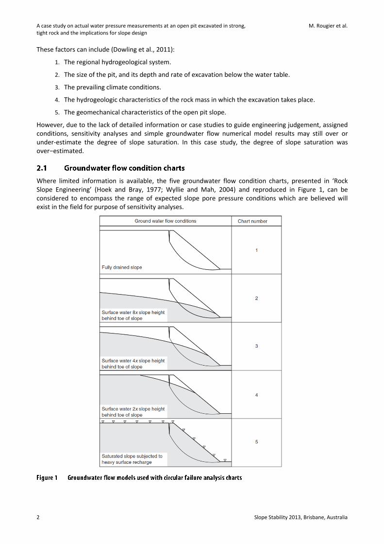
Where limited information is available, the five groundwater flow condition charts, presented in ‘Rock Slope Engineering’ (Hoek and Bray, 1977; Wyllie and Mah, 2004) and reproduced in Figure 1, can be considered to encompass the range of expected slope pore pressure conditions which are believed will exist in the field for purpose of sensitivity analyses.
Remediation
Slope Stability 2013, Brisbane, Australia 3
Application of these groundwater cases can lead to unrealistic high pore pressures for the slope design, if not taken with the understanding of the rock mass hydrogeological behaviour. For example, based on the understanding that the open pit in this case study was in tight rock, the initial groundwater flow assumption assigned was Case 5, i.e. saturated slope subjected to heavy surface recharge. At the time this appeared to be a reasonable first estimate. The pit had been described as tight and guidelines on defining heavy surface recharge were limited. However, unacceptably low slope stability results were obtained for this assumption, and there was a need for quantitative data in order to address the reasonableness of the assumptions and results.
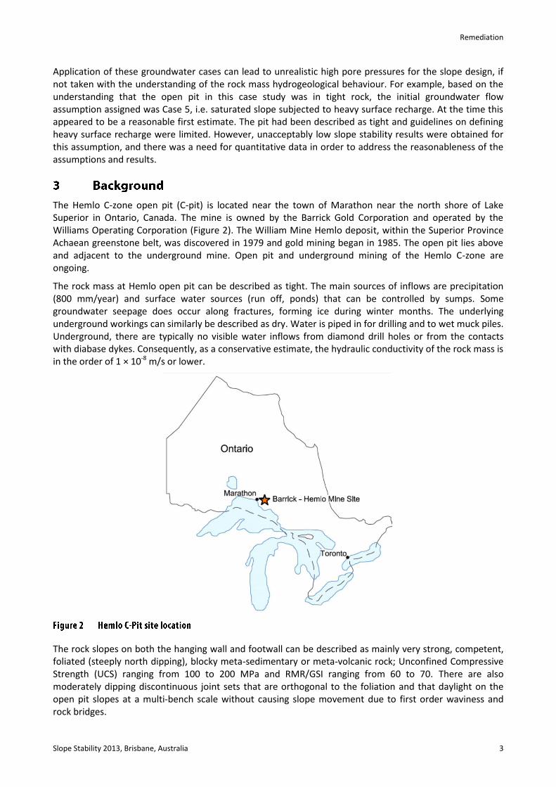
The Hemlo C-zone open pit (C-pit) is located near the town of Marathon near the north shore of Lake Superior in Ontario, Canada. The mine is owned by the Barrick Gold Corporation and operated by the Williams Operating Corporation (Figure 2). The William Mine Hemlo deposit, within the Superior Province Achaean greenstone belt, was discovered in 1979 and gold mining began in 1985. The open pit lies above and adjacent to the underground mine. Open pit and underground mining of the Hemlo C-zone are ongoing.
The rock mass at Hemlo open pit can be described as tight. The main sources of inflows are precipitation (800 mm/year) and surface water sources (run off, ponds) that can be controlled by sumps. Some groundwater seepage does occur along fractures, forming ice during winter months. The underlying underground workings can similarly be described as dry. Water is piped in for drilling and to wet muck piles. Underground, there are typically no visible water inflows from diamond drill holes or from the contacts with diabase dykes. Consequently, as a conservative estimate, the hydraulic conductivity of the rock mass is in the order of 1 × 10⁻⁸ m/s or lower.
The rock slopes on both the hanging wall and footwall can be described as mainly very strong, competent, foliated (steeply north dipping), blocky meta-sedimentary or meta-volcanic rock; Unconfined Compressive Strength (UCS) ranging from 100 to 200 MPa and RMR/GSI ranging from 60 to 70. There are also moderately dipping discontinuous joint sets that are orthogonal to the foliation and that daylight on the open pit slopes at a multi-bench scale without causing slope movement due to first order waviness and rock bridges.
A case study on actual water pressure measurements at an open pit excavated in strong, M. Rougier et al. tight rock and the implications for slope design
4 Slope Stability 2013, Brisbane, Australia
While no slope movement monitoring documentation using prisms or other quantitative measurement exists, open pit slopes up to 130 m high at the time of the study have been developed with no observable overall slope movement or formation of tension cracks behind the pit crest. Slopes of up to 200 m have since been developed with similar positive performance.
A first phase of open pit mining had neared completion (Tier 1, pit depth 130 m). As part of due diligence, overall slope rock mass failure stability assessments of pit deepening to the Tier 2 pit bottom (depth of 200 m at 52 degrees overall) and for future, deeper, expansions were required by the mine.
The challenge was that the geotechnical engineer had only qualitative information on the slope pore pressure conditions for Tier 1 and the understanding that the pre-mining water table was shallow; at above the top of bedrock. Two-dimensional (2D) slope stability analyses were carried out using limit equilibrium and finite element analyses, very low hydraulic conductivity values and conservative assumptions of the groundwater flow conditions for pit deepening to 200 m.
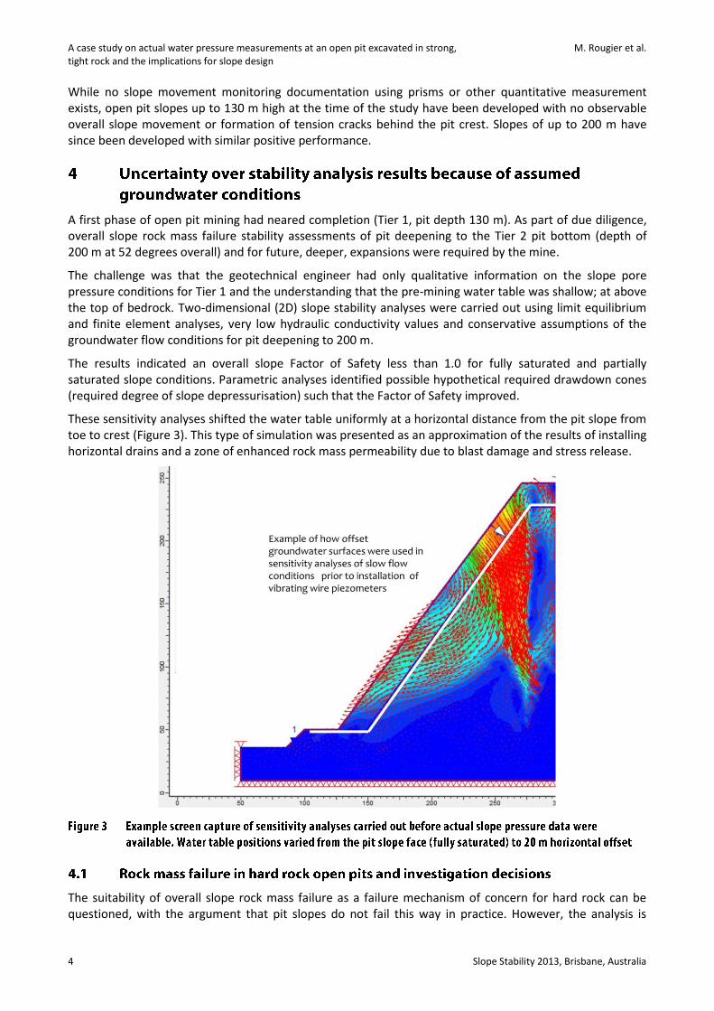
The results indicated an overall slope Factor of Safety less than 1.0 for fully saturated and partially saturated slope conditions. Parametric analyses identified possible hypothetical required drawdown cones (required degree of slope depressurisation) such that the Factor of Safety improved.
These sensitivity analyses shifted the water table uniformly at a horizontal distance from the pit slope from toe to crest (Figure 3). This type of simulation was presented as an approximation of the results of installing horizontal drains and a zone of enhanced rock mass permeability due to blast damage and stress release.
The suitability of overall slope rock mass failure as a failure mechanism of concern for hard rock can be questioned, with the argument that pit slopes do not fail this way in practice. However, the analysis is
Remediation
Slope Stability 2013, Brisbane, Australia 5
typically expected at least at an early stage of slope design to demonstrate and quantify whether or not rock mass failure could develop for the proposed slope geometries.
Consequently, given the unacceptably low Factors of Safety and shear stress reduction analysis results; and given the lack of quantitative pore pressure data, the review team identified that stability analyses required follow-up. The most effective follow-up was deemed to be the measurement of actual pore pressures with vibrating wire piezometers. Packer testing would be of little value for the stability analyses as it would only confirm the low hydraulic conductivities of the rock masses as observed in the open pit and underground workings. There was insufficient information for meaningful slope pore pressure or coupled slope stability and pore pressure modelling.
Another slope stability consideration was that the highwall slope contained a pervasive, in-dipping foliation on which the potential for deep-seated toppling could occur; a failure mechanism that is also sensitive to pore water pressure. On the footwall of the same pit, the bench face angle consistently breaks back to foliation, which is parallel to the pit wall and dipping north. This reinforced the notion that deep-seated toppling had some potential to occur as the pit deepened to 400 m on the opposite wall (the north wall), however low the potential could be.
Photogrammetric mapping (Mathis, 2011) indicated the occurrence of inter-ramp scale joint planes with 45 degree dip that had already daylighted on the existing slope without movement, which was attributed to rock bridges. Finally, as part of the open pit expansion studies, 3D groundwater flow numerical models were required for risk and impact assessments and the permitting process. These considerations justified looking for opportunity to install vibrating wire piezometers for short term and long term observations. It was later also identified that such installations might also be useful for demonstrating the validity of hydrogeological assumptions as mining continued, for both environmental permitting and geotechnical aspects.
The open pit was in the process of drilling deep exploration drillholes parallel to the pit wall and located 50 to 100 m behind the pit crest, for potential pit expansion to assess pore water conditions on the highwall. Suitably located, recently capped drillholes were opportunistically re-opened by drilling through the cement plugs at the collar, reamed, and then completed with fully grouted vibrating wire piezometers. Several target inclined in-pit drillholes were also completed to collect additional pore pressure data at complimentary positions on the open pit slope.
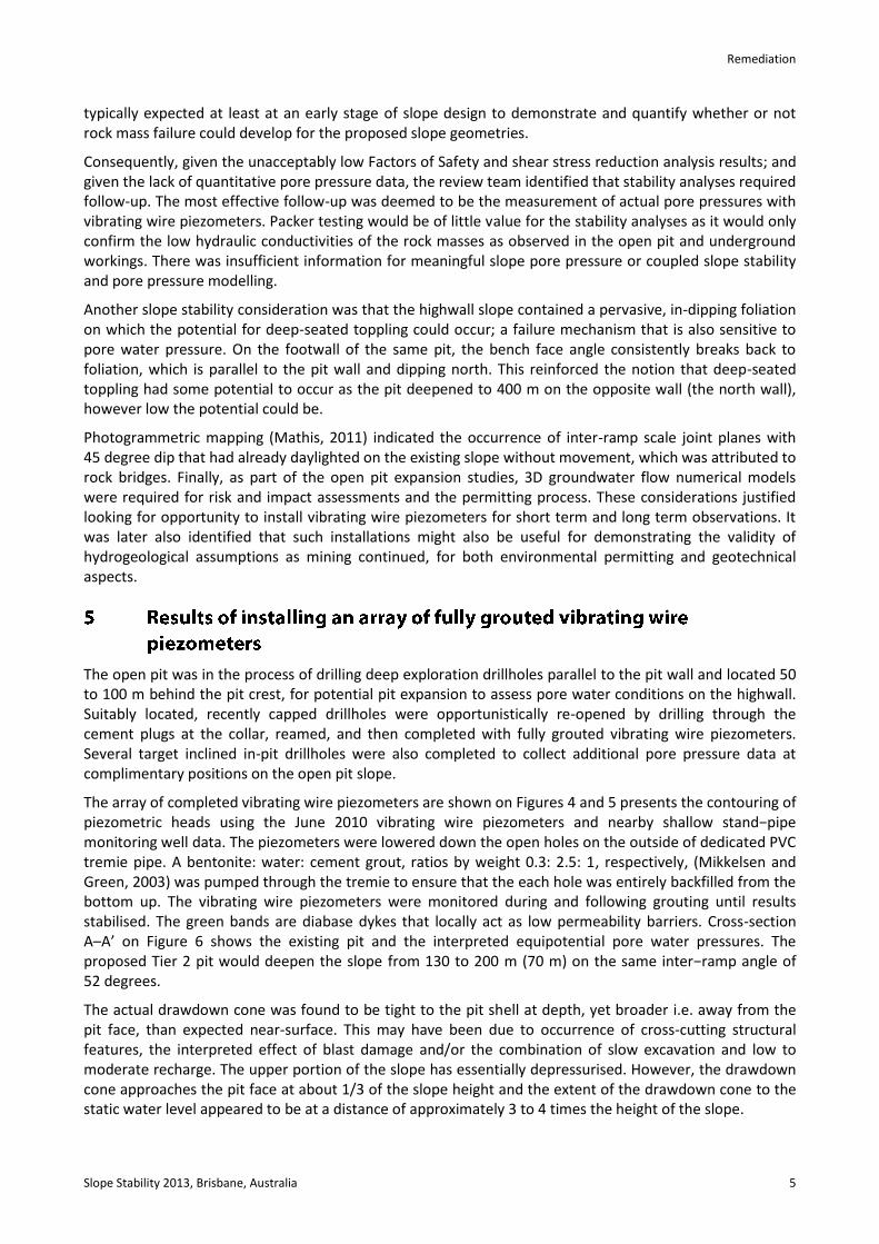
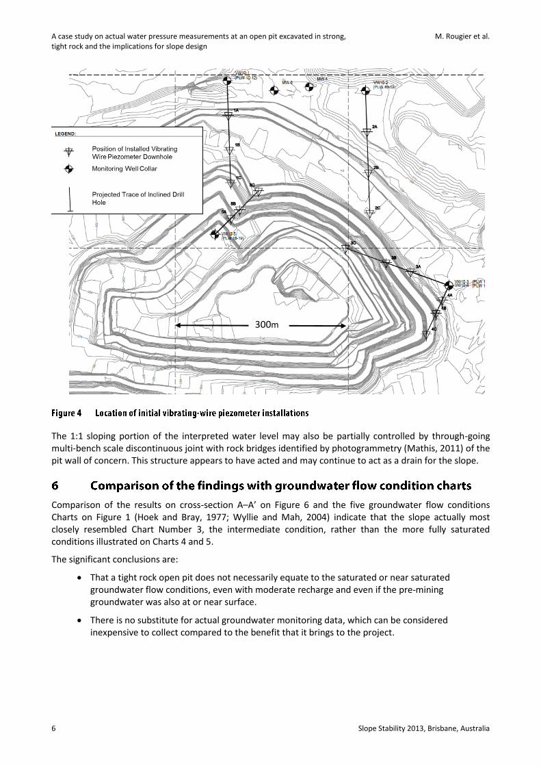
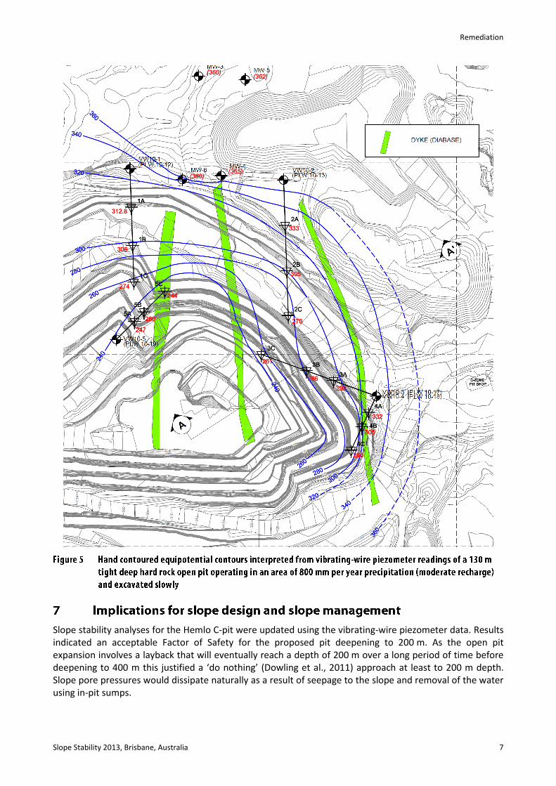
The array of completed vibrating wire piezometers are shown on Figures 4 and 5 presents the contouring of piezometric heads using the June 2010 vibrating wire piezometers and nearby shallow stand−pipe monitoring well data. The piezometers were lowered down the open holes on the outside of dedicated PVC tremie pipe. A bentonite: water: cement grout, ratios by weight 0.3: 2.5: 1, respectively, (Mikkelsen and Green, 2003) was pumped through the tremie to ensure that the each hole was entirely backfilled from the bottom up. The vibrating wire piezometers were monitored during and following grouting until results stabilised. The green bands are diabase dykes that locally act as low permeability barriers. Cross-section A–A’ on Figure 6 shows the existing pit and the interpreted equipotential pore water pressures. The proposed Tier 2 pit would deepen the slope from 130 to 200 m (70 m) on the same inter−ramp angle of 52 degrees.
The actual drawdown cone was found to be tight to the pit shell at depth, yet broader i.e. away from the pit face, than expected near-surface. This may have been due to occurrence of cross-cutting structural features, the interpreted effect of blast damage and/or the combination of slow excavation and low to moderate recharge. The upper portion of the slope has essentially depressurised. However, the drawdown cone approaches the pit face at about 1/3 of the slope height and the extent of the drawdown cone to the static water level appeared to be at a distance of approximately 3 to 4 times the height of the slope.
A case study on actual water pressure measurements at an open pit excavated in strong, M. Rougier et al. tight rock and the implications for slope design
6 Slope Stability 2013, Brisbane, Australia
The 1:1 sloping portion of the interpreted water level may also be partially controlled by through-going multi-bench scale discontinuous joint with rock bridges identified by photogrammetry (Mathis, 2011) of the pit wall of concern. This structure appears to have acted and may continue to act as a drain for the slope.
Comparison of the results on cross-section A–A’ on Figure 6 and the five groundwater flow conditions Charts on Figure 1 (Hoek and Bray, 1977; Wyllie and Mah, 2004) indicate that the slope actually most closely resembled Chart Number 3, the intermediate condition, rather than the more fully saturated conditions illustrated on Charts 4 and 5.
The significant conclusions are:
That a tight rock open pit does not necessarily equate to the saturated or near saturated groundwater flow conditions, even with moderate recharge and even if the pre-mining groundwater was also at or near surface.
There is no substitute for actual groundwater monitoring data, which can be considered inexpensive to collect compared to the benefit that it brings to the project.
300m
Remediation
Slope Stability 2013, Brisbane, Australia 7
Slope stability analyses for the Hemlo C-pit were updated using the vibrating-wire piezometer data. Results indicated an acceptable Factor of Safety for the proposed pit deepening to 200 m. As the open pit expansion involves a layback that will eventually reach a depth of 200 m over a long period of time before deepening to 400 m this justified a ‘do nothing’ (Dowling et al., 2011) approach at least to 200 m depth. Slope pore pressures would dissipate naturally as a result of seepage to the slope and removal of the water using in-pit sumps.
A case study on actual water pressure measurements at an open pit excavated in strong, M. Rougier et al. tight rock and the implications for slope design
8 Slope Stability 2013, Brisbane, Australia
As described in Dowling et al. (2011), this approach is applicable in situations where the rock mass in the pit has a relatively low permeability and is also strong, and there are both:
1. High tolerance to groundwater pressure in the slope design.
2. Relatively low amounts of groundwater flow and volume entering the pit, and low impacts to mine operations.
For the pit deepening having had a small number of vibrating wire piezometers with which to monitor the highwall slope depressurising, such as those that are part of the discussion in this paper, would have reduced the amount of speculation in early stability analyses.
The authors of this paper recommend that even for tight rock open pit slopes where slope pore pressure conditions are favourable that a minimum amount of targeted slope groundwater condition monitoring (i.e. piezometers) be planned and part of a routine geotechnical monitoring. Actual pore pressure values will allow quantitative evidence to monitor performance and verify assumptions about the engineering geology model as the pit deepens. Should ground conditions and slope performance change from what was anticipated as mining occurs, then the vibrating-wire piezometer baseline data from hydrographs will contribute to the reinterpretation. Should trial horizontal drains be required, the pre-existing vibrating wire piezometers may serve as immediate targets to assess performance of drains and assess an effective spacing for drains. Piezometers may also be used to help evaluate the width of a zone of enhanced permeability due to blast damage behind the slope face. Such long term monitoring can have other multiple uses and benefits to the project for geotechnical and environmental reasons. It would allow for confirmation of initial assumptions about slope behaviour.
This paper presents the case study results of tight, hard rock slope pore pressure observations in an area of moderate recharge where 130 m deep open pit slopes were developed slowly. The groundwater flow condition observed can be described as intermediate, between fully saturated and completely dewatered. It shows significantly more dewatering of the rock mass near surface than initially anticipated, which is better than the more saturated conditions that were initially considered for purposes of stability analyses.
Remediation
Slope Stability 2013, Brisbane, Australia 9
Look-up tables and type-models are useful tools in the absence of data for the preliminary estimation of phreatic surfaces, but they can lead to over-conservative slope designs. There is nothing better than having actual piezometer data.
Vibrating-wire installations to pro-actively monitor pore pressure response are strongly recommended as part of best practice geotechnical and hydrogeological monitoring during operations even for pits whose slope design and slope performance are relatively insensitive to groundwater.
The number of such installations required to remove uncertainty do not need to be onerous, particularly for a hard rock pit where expansion and deepening may occur. There should be enough piezomters to answer basic questions about drawdown of the phreatic surface as excavations advance, for due diligence and planning purposes.
Thanks to Bob Sharon for his technical endorsement during the early stages of the field study and thanks to Jim Mathis for his observations and insights on the structural fabric at Hemlo. Thanks to Duncan Quick at William Mine for collecting the data from the vibrating-wire piezometer hydrographs on top of his other duties. Thanks to Allison Henstridge and the mining team at Williams Mine for their support.
Publication of case studies and detailed information is required for advancement in the field. Barrick Gold’s permission to publish is gratefully acknowledged.
Dowling, J., Reidel, J. and Beale, G. (2011) A Review of Key Factors Affecting Mine Dewatering and Slope Depressurization, in Proceedings International Symposium on Rock Slope Stability in Open Pit Mining and Civil Engineering (Slope Stability 2011), E. Eberhardt and D. Stead (eds), 18–21 September 2011, Vancouver, Canada, Canadian Rock Mechanics Association, Canada, CD-rom only.
Hoek, E. and Bray, J. (1977) Rock Slope Engineering, Revised 2nd ed., groundwater condition chart in Chapter 9 on p. 233, Institute of Mining and Metallurgy, Spon Press, London, 402 p.
Mathis, J.I. (2011) Photogrammetric Discontinuity Mapping as Applied to Structural Interpretation and Drillhole Planning at Barrick’s Williams Pit, in Proceedings International Symposium on Rock Slope Stability in Open Pit Mining and Civil Engineering (Slope Stability 2011), E. Eberhardt and D. Stead (eds), 18–21 September 2011, Vancouver, Canada, Canadian Rock Mechanics Association, Canada, CD-rom only.
Mikkelsen, P.E. and Green, G.E. (2003) Piezometers in Fully-Grouted Boreholes, Field Measurements in Geomechanics, in Proceedings of the 6th International Symposium on Geomechanics, F. Myrvoll (ed), September 2003, Oslo, Norway, pp. 545–553.
Read, J. and Stacey, P. (2009) Guidelines for Open Pit Slope Design, CSIRO Publishing, Taylor & Francis Group, Spon Press, London, New York, 496 p.
Wyllie, D. and Mah, W. (2004) Rock Slope Engineering, Civil and Mining, 4th Edition, Figure 8.4 on page 182 in Chapter 8, Spon Press, Taylor Francis Group, London and New York, 431 p.

A case study on actual water pressure measurements at an open pit excavated in strong, M. Rougier et al. tight rock and the implications for slope design
10 Slope Stability 2013, Brisbane, Australia


![Beam stability on an elastic foundation subjected to ... · An elastic stability problem of non-conservative ... ported Timoshenko's beam [8]. Recently, Maurizi and Bambill verified](https://img.pdfslide.us/doc/110x75/5acb28367f8b9a73128b4fe2/beam-stability-on-an-elastic-foundation-subjected-to-elastic-stability-problem.jpg)