Embed Size (px)
Citation preview

AIMETA 2017
XXIII Conference
The Italian Association of Theoretical and Applied Mechanics
Luigi Ascione, Valentino Berardi, Luciano Feo, Fernando Fraternali and Antonio Michele Tralli (eds.)
Salerno, Italy, 4-7 September 2017
THE EUROPEAN PROJECT SUREBRIDGE –
A CASE STUDY IN TUSCANY
Paolo S. Valvo1, Erika Davini1, Cristiano Alocci1, Antonfranco Pasquale2,
Fabio Ricci2, Juan Carlos Miranda Santos2, Martijn Veltkamp3, Reza Haghani4
1 Department of Civil and Industrial Engineering, University of Pisa
Largo Lucio Lazzarino, 56122 Pisa, Italy
e-mail: [email protected]
2 A.I.C.E. Consulting S.r.l.
Via G. Boccaccio, 20, 56017 San Giuliano Terme (Pisa), Italy
e-mail: [email protected]
3 FiberCore Europe
Oostdijk 25, 3077 CP Rotterdam, The Netherlands
e-mail: [email protected]
4 Department of Civil and Environmental Engineering, Chalmers University of Technology
Sven Hultins gata, 8, 412 96 Gothenburg, Sweden
e-mail: [email protected]
Keywords: road bridges, structural strengthening, fibre-reinforced composite materials.
Abstract. The European project SUREBridge (Sustainable Refurbishment of Existing Bridges)
is developing a new concept for the refurbishment of road bridges. The proposed technique
takes advantage of the peculiarities of fibre-reinforced materials to perform upgrading, re-
pair, and strengthening in an effective and efficient way in terms of resource consumption,
waste production, construction time, and traffic disruption.
The technique applies to bridges with reinforced concrete slab and longitudinal girders made
of either reinforced concrete or steel. Longitudinal girders are strengthened by bonding car-
bon fibre-reinforced polymer (CFRP) laminates to their bottom surfaces. Higher structural
performances are achieved by pre-stressing the CFRP laminates. The existing concrete slab
is not demolished, with savings in both construction time and waste production. Instead, tai-
lor-made glass fibre-reinforced polymer (GFRP) panels are connected to the deck to increase
its overall bending strength. Furthermore, GFRP panels enable the widening of the road sec-
tion, if necessary to upgrade the bridge to increased traffic demand.
This paper presents the application of the SUREBridge technique to a real bridge located in
San Miniato, Tuscany, Italy. The designed intervention includes both the widening of the road
section and the structural strengthening of the deck to comply with current traffic loads.
1998

Paolo S. Valvo, Erika Davini and others
1 INTRODUCTION
Bridges are critical transport infrastructures, fundamental for the performance of the road
and railway transport network. Today, bridge owners and managers are dealing with a large
number of structurally deficient and obsolete bridges. With the expected increase in the traffic
volume, existing bridges will be subjected to more severe actions and, consequently, the need
to refurbish these infrastructures will increase dramatically. In this context, refurbishment in-
cludes not only structural strengthening, repair, and upgrading, but also geometric changes,
such as the widening of the bridge deck to provide more traffic capacity.
At present, construction and maintenance activities relating to bridges imply economical
and time expensive procedures, with a negative impact on traffic flow and welfare in wider
terms. In addition to disturbance, disruption, and pollution, other main challenges are the inef-
ficient use of resources, i.e. materials, energy, waste management, and recycling.
In this paper, we present an innovative solution developed within the European project
SUREBridge for the refurbishment of road bridges along with its application to a real bridge
selected as case study.
2 THE SUREBRIDGE PROJECT
2.1 Basic concept
The European research project SUREBridge (Sustainable Refurbishment of Existing
Bridges) is developing a new concept for the refurbishment of road bridges. The proposal is
addressed to concrete and steel-concrete bridges, which are usually affected by strength defi-
ciencies linked to the concrete slab [1].
The target is to exploit the remaining capacity of the superstructure, preserving the struc-
tural elements of the deck (girders and slab) and increasing the load-carrying capacity to the
desired level. This is achieved by using light-weight, tailor-made glass fibre-reinforced poly-
mer (GFRP) sandwich panels [2], installed on the existing concrete slab, and carbon fibre-
reinforced polymer (CFRP) laminates applied to the bottom side of the girders. Such lami-
nates are pre-stressed using an innovative technique, which avoids tensional peaks at the lam-
inate ends [3]. Furthermore, the GFRP panels can be manufactured of the same width or wider
than the existing deck, as shown in Figure 1, enabling to widen the road section if needed.
a)
b)
Figure 1: a) Refurbishment and b) Refurbishment and widening of an existing bridge deck.
+
� �
+
1999

Paolo S. Valvo, Erika Davini and others
2.2 Theoretical and experimental behaviour of FRP strengthened beams
Figure 2a shows the cross section of a reinforced concrete beam, chosen as a prototype to
demonstrate the effectiveness of the strengthening technique developed within the SURE-
Bridge project. This T-shaped cross section schematically represents the typical girder and
slab elements used in road bridges. Figure 2b illustrates the same cross section strengthened
with the SUREBridge technique.
a) b)
Figure 2: Prototype reinforced concrete beam: a) un-strengthened; b) strengthened.
Large-scale, 6-m long specimens having the described cross sections are currently (July
2017) being tested under four-point bending (Figure 3) in the laboratory of the Structural En-
gineering Division of the Department of Civil and Environmental Engineering at Chalmers
University of Technology.
The resisting bending moment of the strengthened composite section, Mrd, has been evalu-
ated by extending to the present case the normally accepted hypotheses for ultimate limit state
(ULS) verifications of reinforced concrete elements (Section 6.1 of Eurocode 2 [4]):
• plane sections remain plane with no relative sliding between concrete and steel;
• the tensile strength of concrete is ignored;
• the stresses in concrete in compression are derived from the design stress-strain rela-
tionships given in Section 3.1.7 of Eurocode 2 [4]. In particular, here a bilinear stress-
strain relationship has been used;
• elastic-plastic behaviour is assumed for steel reinforcements.
In addition to the above, further specific assumptions have been made:
• the whole composite section remains plane after deformation with no relative sliding
between CFRP/GFRP elements and concrete;
• both CFRP and GFRP are assumed to behave as elastic-brittle materials;
• delamination of CFRP/GFRP from concrete is not taken into account.
2000

Paolo S. Valvo, Erika Davini and others
Figure 3: Test configuration for strengthened prototype beam.
Analytical details about the resulting mechanical model are omitted here for brevity, but
can be found in a dedicated deliverable of the project [5]. The model has been implemented
into a software tool, which furnishes the ultimate bending moment of the strengthened section.
To validate the above-mentioned hypotheses, non-linear static analyses have been carried
out on refined finite element models of the large-scale prototype beams using the commercial
software Straus7® [6]. A fibre-element modelling approach, frequently used for push-over
seismic analyses, has been chosen since it represents a good compromise between simplicity
of implementation and accuracy of results in material non-linear analyses [7] [8].
Figure 4 shows the un-strengthened and strengthened cross sections of the modelled beams.
The mechanical properties of the materials are summarised in Table 1.
a) b)
Figure 4:Finite element model for a) un-strengthened beam; b) strengthened beam with the SUREBridge solution.
Characteristic strength
(MPa)
Elastic modulus
(MPa)
Concrete (in compression) 43 34077
Steel 500 210000
CFRP 3000 210000
GFRP (webs in longitudinal direction) 491 38200
Table 1: Mechanical properties of the materials.
2001

Paolo S. Valvo, Erika Davini and others
Figure 5 shows the theoretical load-deflection curves obtained from analyses in terms of
the total applied load, F, and mid-span deflection. Table 2 compares the finite element anal-
yses results and the predictions made with the software tool on the ultimate bending moment,
Mrd, and the corresponding failure load, Fu.
a)
b)
Figure 5: Load-deflection curves: a) un-strengthened beam; b) strengthened beam.
Software tool Finite element analysis
Fu (kN) Mrd (kNm) Fu (kN) Mrd (kNm)
Un-strengthened beam 126 139 135 148.5
Strengthened beam 418 460 397 437
Table 2: Comparison between the results of the software tool and the finite element analysis.
2002

Paolo S. Valvo, Erika Davini and others
3 STRUCTURAL ANALYSIS OF THE SAN MINIATO BRIDGE
3.1 A case study in Tuscany: the San Miniato bridge
In order to evaluate the effectiveness of the SUREBridge solution, its application to a real
bridge has been analysed [9]. The selected case study is a bridge crossing the Elsa river and
located in a small town named Isola di San Miniato (Tuscany, Italy), from now on referred to
as the “San Miniato bridge” (Figure 6).
a) b)
c) d)
Figure 6: Location of the San Miniato bridge: a) in Italy; b) within Tuscany;
c) within the Municipality of San Miniato; d) satellite view of the bridge.
The bridge has a length of nearly 60 m subdivided into four spans of 15 m each. The 3-m
wide deck, crossed by vehicles one way alternatively, is composed of a 160-mm thick, cast-
on-site concrete slab and four prefabricated pre-stressed concrete girders, 1 m high and 1 m
distant one from another.
2003

Paolo S. Valvo, Erika Davini and others
The original documents indicate that the bridge was designed by the Italian engineer Fran-
cesco Lorenzi and built in 1968. The construction was motivated by the collapse of a pedes-
trian iron bridge, caused by the riverbed lowering and constant erosion of the banks. Such
phenomena were in turn due to the strong flows and vortices between the Arno river and a
nearby dyke, collapsed too some years later.
3.2 Structural investigations
The San Miniato bridge has been the subject of a structural investigation conducted in
2006 by the engineering company A.I.C.E. Consulting S.r.l. The Client was the Province of
Pisa, as the Authority owning the bridge and responsible for its maintenance. After the dam-
age of a railing, the Client had decided to lead an investigation campaign on the bridge to
highlight possible other degradation issues and to evaluate the residual load-carrying capacity.
The first step of the investigation campaign was an on-site visual inspection (Figure 7a).
From this inspection, some of the main problems affecting the bridge were immediately ap-
parent: corrosion and breakage of some pre-stressing wires (Figure 7b), concrete spalling and
reinforcement corrosion (Figure 7c), and general degradation of concrete surfaces (Figure 7d).
a) b)
c) d)
Figure 7: Visual inspection on the bridge: a) General view; b) Corrosion of pre-stressing wires;
c) Concrete spalling and reinforcement corrosion; d) Degradation of concrete surfaces.
A survey and testing plan was developed involving sclerometric and ultrasonic tests, as
well as dynamic acquisitions. The values of the mechanical properties of concrete to be used
in structural modelling and verifications were obtained from in-situ tests. Instead, since the
types of steel used in the construction were clearly indicated in the original design documents,
it was decided not to take samples of reinforcement bars and wires, but only to verify their
2004

Paolo S. Valvo, Erika Davini and others
positions and diameters by using a pacometer and make spot checks by removing the superfi-
cial concrete layers.
From dynamic acquisitions, the natural frequencies and mode shapes were obtained. These
were later used to calibrate the finite element model of the bridge. The first natural frequen-
cies obtained were 8.6–9.2 Hz for the flexural modes and 12.5–13.3 Hz for the torsional
modes, as can be seen in Table 3, where the notation “ADx” indicates the dynamic test done
at a specific point of the structure (Figure 8).
a)
b)
Figure 8: Position of the dynamic acquisitions: a) plan view of the whole bridge; b) detail of the first span.
Test Channel f1 (Hz) f2 (Hz)
AD1 CH0 9.2 12.9
CH1 9.2 12.9
AD2 CH0 8.6 12.5
CH1 8.6 12.5
AD3 CH0 8.9 13.3
CH1 8.9 13.3
AD4 CH0 8.6 –
CH1 8.6 –
Table 3: Experimental natural frequencies.
3.3 Finite element model of the existing bridge
A finite element model of the bridge (Figure 9) has been created by using the commercial
finite element software Straus7® [6]. The outcomes of the experimental campaign were used
to define the geometry of the BEAM and PLATE elements, as well as the mechanical properties
of the materials, the internal and external constraints. Table 4 summarises the mechanical
properties of the materials, obtained from the original documents and the in-situ investigation
campaign.
2005

Paolo S. Valvo, Erika Davini and others
Figure 9: Finite element model of the bridge.
Part Property Value Source
Girder
Unit weight 25 kN/m3 literature
Elastic modulus 36000 MPa on-site ultrasonic test
Poisson coefficient 0.1 literature
Density 2500 kg/m3 literature
Pier
Unit weight 25 kN/m3 literature
Elastic modulus 29500 MPa on-site ultrasonic test
Poisson coefficient 0.1 literature
Density 2500 kg/m3 literature
Slab
Unit weight 25 kN/m3 literature
Elastic modulus 31200 MPa on-site ultrasonic test
Poisson coefficient 0.1 literature
Density 2500 kg/m3 literature
Table 4: Mechanical properties of the materials.
3.4 Dynamic modal analysis
The dynamic modal analysis is needed to determine the theoretical natural frequencies and
mode shapes of the structure to be compared with the experimental results obtained from in-
situ dynamic acquisitions (see Section 3.2). No force loads were considered, but only the
masses of the structural and non-structural elements, such as the road pavement and railing.
The mass of the structural elements is automatically calculated by the software and at-
tributed to the nodes of the model, once the geometry and material properties of each element
are defined, while the masses of the road pavement and railing are introduced into the model
as NON-STRUCTURAL MASS per unit area of the PLATE elements representing the concrete
slab.Table 5 summarises the natural frequencies of the first vibration modes obtained from the
dynamic modal analysis of the structure. The modes with the higher mass participation factors
are given in boldface character. A good agreement has been obtained between the experi-
mental results (Table 3) and the output of the analysis, so that the model was considered well
calibrated.
2006

Paolo S. Valvo, Erika Davini and others
Mass participation factor
Mode Theoretical
frequency (Hz) X (%) Y (%) Z (%)
1 6.435 16.702 0.000 19.681
2 6.585 0.000 56.824 0.000
3 7.233 0.139 0.000 0.288
4 8.308 1.046 0.000 0.002
5 9.259 1.636 0.000 35.624
6 9.676 0.000 0.048 0.006
7 10.72 0.000 2.313 0.000
8 11.08 0.000 5.809 0.000
9 11.52 60.099 0.000 8.151
10 12.40 0.000 0.062 0.000
11 12.47 0.000 1.365 0.000
12 14.86 0.000 16.276 0.000
Table 5: Theoretical and experimental natural frequencies.
3.5 Linear static analysis
The bridge was designed following the Italian regulations of the time of construction,
namely the Circolare n. 1398/1965 [10] and the Circolare n. 384/1962 [11]. In order to assess
the current load-carrying capacity of the bridge, static analysis of the model was carried out
considering the load configurations and combinations according to the present Italian regula-
tion NTC 2008 [12]. Such loads have been applied per unit area or unit length for the PLATE
and the BEAM elements, respectively.
The stresses on the structural elements of the bridge have been determined for the single
load cases and their combinations. The most unfavourable combinations used for structural
verifications are presented in Table 6. Table 7 shows the strength demand obtained from the
linear static analysis in terms of design bending moment, Msd, and shear force, Vsd, compared
to the corresponding capacities of the composite section (girder + concrete slab), Mrd and Vrd,
evaluated according to NTC 2008 [12].
The structural analysis of the bridge has revealed that the composite girder sections present
both flexural and shear strength lacks. In addition, pre-stressing has to be restored in one of
the border beams featuring some damaged wires (see Figure 7b). Furthermore, the road sec-
tion turns out to be not sufficient for the road category assigned to the San Miniato bridge by
Italian road regulations [13], so that it needs to be properly widened. Lastly, local analysis of
the concrete slab has highlighted the need for both flexural and shear strengthening of this el-
ement in the transverse direction.
2007

Paolo S. Valvo, Erika Davini and others
Verification Loads Leading
load
Traffic load
configuration
Load
combination
Bending
moment
Self-weight
(G1)
Traffic
(Qt)
1.3*G1+
1.5*G2+
1.5*0.6*Qw+
1.35*Qt
Permanent loads
(G2)
Wind
(Qw)
Traffic
(Qt)
Shear
stress
Self – weight
(G1)
Traffic
(Qt)
1.3*G1+
1.5*G2+
1.5*0.6*Qw+
1.35*Qt
Permanent loads
(G2)
Wind
(Qw)
Traffic
(Qt)
Table 6: Load combinations for the ULS verifications.
Section Msd (kNm) Mrd (kNm) Vsd (kN) Vrd (kN)
Internal girder 1231 991 360 285
Border girder 1156 962 260 285
Damaged border girder 1156 721 260 285
Table 7: Maximum design internal forces and corresponding resistances.
3.6 Preliminary design of the strengthening intervention
Several widening hypotheses have been evaluated to make the road section compliant with
current Italian road regulations [13]. After a preliminary analysis, it was decided to choose a
single lane solution with the widening of the existing deck from 3 to 3.5 m and the addition of
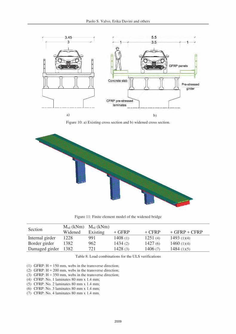
two lateral walkways (Figure 10).
A new finite element model (Figure 11) representing the widened structure has been creat-
ed to evaluate the increase in the demand. The resisting bending moment of the composite
section, Mrd, at the ultimate limit state has been evaluated according to the hypotheses illus-
trated in Section 2.2. Table 8 shows the demand and capacity in terms of bending moment of
the composite section obtained by using GFRP panels or CFRP laminates only, and the
SUREBridge solution, which uses both. The benefits of the SUREBridge solution are clear:
the ultimate bending moment can be considerably increased from 721 to 1484 kNm, above the
design value of 1382 kNm. Furthermore, using the GFRP panels only would require very
thick panels for the damaged border girder. In addition, using pre-stressed CFRP laminates
only would imply a brittle failure of concrete in compression, since the limit strain of CFRP
laminates has not been reduced with respect to material strength as prescribed by the Italian
standard CNR-DT 200 R1/2013 to avoid intermediate delamination failure [14]. This limita-
tion is valid just for passive laminates, due to the benefits of the CFRP pre-stressing technique
on the concrete section [3].
2008
Paolo S. Valvo, Erika Davini and others
a)
b)
Figure 10: a) Existing cross section and b) widened cross section.
Figure 11: Finite element model of the widened bridge
Section Msd (kNm) Mrd (kNm)
Widened Existing + GFRP + CFRP + GFRP + CFRP
Internal girder 1228 991 1408 (1) 1251 (4) 1493 (1)(4)
Border girder 1382 962 1434 (2) 1427 (6) 1460 (1)(4)
Damaged girder 1382 721 1428 (3) 1406 (7) 1484 (1)(5)
Table 8: Load combinations for the ULS verifications
(1) GFRP: H = 150 mm, webs in the transverse direction;
(2) GFRP: H = 200 mm, webs in the transverse direction;
(3) GFRP: H = 350 mm, webs in the transverse direction;
(4) CFRP: No. 1 laminates 80 mm x 1.4 mm;
(5) CFRP: No. 2 laminates 80 mm x 1.4 mm;
(6) CFRP: No. 3 laminates 80 mm x 1.4 mm;
(7) CFRP: No. 4 laminates 80 mm x 1.4 mm.
2009

Paolo S. Valvo, Erika Davini and others
4 CONCLUSIONS
We have presented the innovative solution developed within the European project SURE-
Bridge for the refurbishment of road bridges. The proposed technique applies to bridges with
reinforced concrete slab and longitudinal girders made of either reinforced concrete or steel.
Longitudinal girders are strengthened by bonding pre-stressed CFRP laminates to their bot-
tom surfaces. GFRP panels are connected to the deck to increase its overall bending strength
and to widen the road section, if necessary.
A mechanical model has been developed to evaluate the ULS bending moment of strength-
ened cross sections and implemented into an ad hoc software tool. The results from this sim-
plified model have been validated against the results of non-linear finite element analyses of
suitably chosen prototype beams. Experimental testing of the same prototype beams is cur-
rently (July 2017) in progress.
Application for the strengthening and widening of the San Miniato bridge case study has
demonstrated the feasibility and effectiveness of the proposed technical solution.
ACKNOWLEDGEMENTS
Financial support from the ERA-NET Plus Infravation 2014 Call within the SUREBridge
Project is gratefully acknowledged.
REFERENCES
[1] SUREBridge – Sustainable Refurbishment of Existing Bridges, http://surebridge.eu/
(accessed 1 July 2017).
[2] FiberCore Europe, http://www.fibercore-europe.com (accessed 1 July 2017).
[3] R. Haghani, M. Al-Emrani, R. Kliger, A new method for strengthening concrete struc-
tures using prestressed FRP laminates. 8th International Structural Engineering and
Construction Conference (ISEC 2015), Sydney, Australia, November 23–28, 2015.
[4] EN 1992-1-1:2004, Eurocode 2 – Design of concrete structures – Part 1-1: General
rules and rules for buildings.
[5] SUREBridge – Sustainable Refurbishment of Existing Bridges, Deliverable D4.2 – De-
sign model for innovative FRP refurbishment of concrete deck bridges, 2017.
[6] Strand7 Software Theoretical Manual – Theoretical background to the Straus7 finite el-
ement analysis system, 1st Edition. Strand7 Pty Limited, 2005.
[7] E.C. Chan, Nonlinear geometric, material and time-dependent analysis of reinforced
concrete shells with edge beams. PhD Thesis, University of California, Berkeley, 1982.
[8] E. Spacone, V. Ciampi, F.C. Filippou, Mixed formulation of nonlinear beam finite ele-
ment. Computers & Structures, 1996.
[9] E. Davini, Un caso studio del progetto europeo SUREBridge: il ponte sul fiume Elsa in
località Isola di San Miniato. MSc Thesis, University of Pisa, Pisa, 2016.
[10] Circolare Min. LL.PP. del 23 gennaio 1965, n. 1398, Norme per l’impiego delle struttu-
re in cemento armato precompresso.
[11] Circolare del Consiglio Superiore del Ministero dei LL.PP. del 14 febbraio 1962, n. 384,
Norma relativa ai carichi per il calcolo dei ponti stradali.
[12] D.M. Infrastrutture del 14 gennaio 2008, Nuove norme tecniche per le costruzioni.
2010

Paolo S. Valvo, Erika Davini and others
[13] D.M. Infrastrutture e Trasporti del 5 novembre 2001, n. 6792, Norme funzionali e geo-
metriche per la costruzione delle strade.
[14] CNR-DT 200 R1/2013, Istruzioni per la Progettazione, l’Esecuzione ed il Controllo di
Interventi di Consolidamento Statico mediante l’utilizzo di Compositi Fibrorinforzati,
Consiglio Nazionale delle Ricerche.
2011


![Cesare Davini and Roberto Paroni - core.ac.uk · 804 C. DAVINI AND R. PARONI oftheCalculusofVariationstoshowhowthemethodstudiedin[18]canbemodified inordertocoverfunctionals of the](https://img.pdfslide.us/doc/110x75/5bdffb7609d3f28f578b9d4b/cesare-davini-and-roberto-paroni-coreacuk-804-c-davini-and-r-paroni-ofthecalculusofvariationstoshowhowthemethodstudiedin18canbemodied.jpg)