Embed Size (px)
Citation preview

A Call to (Green) Arms: A Rallying Cry for Green Chemistry and Engineering for CO2 Capture, Utilisation and Storage.
Journal: Green Chemistry
Manuscript ID GC-PER-06-2018-001962.R1
Article Type: Perspective
Date Submitted by the Author: 15-Aug-2018
Complete List of Authors: Leclaire, Julien; Université Claude Bernard Lyon 1 - CNRS, UMR 5246 ICBMS - CSAp Heldebrant, David; Pacific Northwest National Lab, Applied Synthetic Chemistry
Green Chemistry

Please do not adjust margins
Please do not adjust margins
Journal Name
PERSPECTIVE
This journal is © The Royal Society of Chemistry 20xx J. Name., 2017, 00, 1-3 | 1
Received 00th January 20xx,
Accepted 00th January 20xx
DOI: 10.1039/x0xx00000x
www.rsc.org/
A Call to (Green) Arms: A Rallying Cry for Green
Chemistry and Engineering for CO2 Capture, Utilisation
and Storage.
Julien Leclaire and David J. Heldebrant
Abstract
Chemists, engineers, scientists, lend us your ears… Carbon capture, utilisation, and storage (CCUS) is among
the largest challenges on the horizon and we need your help. In this perspective, we focus on identifying
the critical research needs to make CCUS a reality, with an emphasis on how the principles of green
chemistry (GC) and green engineering can be used to help address this challenge. We identify areas where
GC principles can readily improve the energy or atom efficiency of processes or reduce the environmental
impact. Conversely, we also identify dilemmas where the research needs may be at odds with GC principles,
and present potential paths forward to minimise the environmental impacts of chemicals and processes
needed for CCUS. We also walk a different path from conventional perspectives in that we postulate and
introduce potential innovative research directions and concepts (some not yet experimentally validated) in
order to foster innovation, or at least stoke conversation and question why certain approaches have not yet
been attempted. With elements of historical context, technological innovation, critical thinking, and some
humour, we issue a call to arms and hope you may join us in this fight.
Introduction
Anastas and Warner wrote in their seminal work that, “Green
chemistry involves the design and redesign of chemical
syntheses and chemical products to prevent pollution and
thereby solve environmental problems.” Twelve principles of
green chemical engineering came later on to complement the
12 principles of GC and constitute a full set of guidelines for
technical approaches to make processes more
environmentally benign.1, 2
Green chemistry (GC) launched under the auspices of making
chemical processes more environmentally benign. The
majority of early GC research focused on identifying less-toxic
reagents, on reducing the non-renewable inflows and
impacting outflows in order to minimise the global
environmental imprint. GC has many success stories, helping
humanity move the chemical industries away from toxic and
carcinogenic reagents such as phosgene (COCl2), remove
volatile organic compounds (VOCs) and lead from paint,
develop biodegradable plastics and detergents through
catalytic processes (such as metathesis), significantly reduce
the waste production and water consumption, respectively,
associated with drug manufacturing and textile processing. GC
also led to the development of many catalytic processes that
increase yields and rates of chemical processes with reduced
emissions and waste streams.
GC should not be pigeonholed as an environmental
movement; GC is also an economic driver. GC has been shown
to enhance the economics of chemical processes by using
sustainable, renewable energy and resources, sourcing
cheaper and more cost-effective reagents, with increased
atom economy and energy efficiency. Further, less-toxic and
biodegradable reagents and waste streams reduce costs
associated with waste disposal, minimize adverse effects from
exposure to harmful chemicals and avoid bioaccumulation.
This is evident as chemical companies would only adopt new
processes in the absence of regulation if there were a
monetary incentive to do so. Thus, we champion the premise
that any of the 12 principles go beyond making chemical
processes more environmentally benign; they also make
processes cheaper and more streamlined.
Page 1 of 25 Green Chemistry

Please do not adjust margins
Please do not adjust margins
ARTICLE Journal Name
2 | J. Name., 2012, 00, 1-3 This journal is © The Royal Society of Chemistry 20xx
The 12+12 principles of GC and green engineering (GE) have
been used successfully for decades to tackle many individual
chemical processes, though these wins are pale in comparison
with the magnitude of the next challenge on the horizon,
climate change. Among the many potential fields of
application where GC should change the world, the most
obvious and challenging is sustainable development.
Sustainable development encompasses GC and GE because it
involves, beyond the environmentally benign manufacturing
practices, the societal goal to improve human and
environmental well-being. This notion of well-being is
associated with a straightforward and widespread access to a
spectrum of commodities ranging from breathable air,
drinkable water, and affordable energy to manufactured
goods. Apart from the first one, which still is free, the
remaining ones involve a cost in energy for their production
and delivery. Reducing this energy demand, which reaches up
to 15% of global consumption, is undoubtedly a challenge for
green chemists and engineers.3 Regarding the end products
from human activities, this ever-increasing global energy
demand is continually driving the upward trajectory of global
CO2 emissions. The annual volume of global anthropogenic CO2
emissions was 36.8 gigatons in 2017; to put things in
perspective, that amount of CO2 by our calculations would
equal the volume of Crater Lake in Oregon (18 km3) and next
year’s emissions will surpass the volume of Lake Geneva (20
km3). The Intergovernmental Panel on Climate Change drafted
a report that quantified a global “carbon budget” (Fig. 1),4
which is the amount of CO2 emissions that can be emitted with
a high degree of probability of limiting global temperature rise
to the IPCC and COP21 warming target of ~2˚ Celsius above
pre-industrial levels.5,6 As of early 2018, humans have emitted
over 70% of the Earth’s 2,900,000,000,000-ton proposed
carbon budget, suggesting we may exceed the projected global
2 ˚C increase target as agreed upon in the Paris Climate
Accord.6 Thus, there is an urgent need to deploy technologies
that reduce emissions to minimise the greenhouse effect and
potential effects of climate change.
Fig. 1. CO2 budget. CDIAC; NOAA-ESRL; Le Quéré et al. 2017; Global Carbon Budget 2017
4
CCUS (carbon capture, utilisation and storage) is an
encompassing acronym that represents a collection of
chemical sciences and technologies covering the entire life
cycle of CO2. We point to a definitive review of current CCUS
technologies that has recently been reported.7 There is more
to CCUS than just capturing CO2 from anthropogenic sources;
it also includes compression of CO2 for transportation, either
to permanent geological storage or reconstitution into value-
added products. CCUS also includes the industries who
manufacture the infrastructure, and chemical industries who
supply and synthesise materials for capture, waste handling
and disposal, environmental health and safety, and long-term
monitoring. Each of these aspects is energy and cost intensive.
The principles of GC can be used to improve efficiency and
lower costs while also making the processes more
environmentally benign. These processes should not be
considered individual problems; they are a single chain of
value, from cradle to grave, which relies on an integrated
network of multiple disciplines and industries and requires a
synergistic effort to make CCUS successful.
Humankind’s carbon-based fuel cycle has created a colossal
looming challenge, at a scale that borders on the
unfathomable. The removal of gigatons of CO2 will require
gigajoules of energy to power technologies using gigatons of
sorbent, which will require gigatons of solvent to be
synthesised, which begets gigatons of waste. Any realistic
approach to CCUS will have to do less environmental harm
than good. Thus, the paradox is, how can CCUS be green, when
the chemicals, infrastructure, and energy required for CCUS
are so vast? The best way to answer the paradox is to first
identify the components of the problem.
We envision CCUS as a five-headed “hydra” like the creature of
Greek mythology, with each head being a challenge or
opportunity for GC and GE to address (Fig. 2). We identify its
heads as: (1) The operational expenditures (OPEX), which are
the energy inefficiency of capture technologies; (2) The capital
expenditures (CAPEX), which include the materials and process
infrastructure; (3) The life cycle of the capture infrastructure,
spanning synthesis, use, and waste; (4) transportation and
storage of CO2; and (5) utilisation, which includes
reconstitution and storage into value-added products. Each of
these heads has historically been addressed individually, but
unified green approaches are necessary to make CCUS
feasible.
Page 2 of 25Green Chemistry

Please do not adjust margins
Please do not adjust margins
Journal Name ARTICLE
This journal is © The Royal Society of Chemistry 20xx J. Name., 2013, 00, 1-3 | 3
Fig. 2. Conceptual CCUS five-headed Hydra.
Throughout human history, tales have spoken of valiant
heroes who rise to battle the forces of oppression and ride off
into the sunset. With CCUS, there is no Heracles sent from the
gods to lead us in battle, there are no or vorpal blades can go
“snicker-snack” and slay this Jabberwock that humanity has
created. Current efforts in CCUS are attempting to slay each
head individually through compartmentalised and isolated
efforts. As with the beast in Greek mythology, cutting off one
of the CCUS’s heads individually is likely to make it grow two
more. As often in the chemical sciences, replacing a toxic or
harmful substance with a new greener alternative may result
in unintended and unforeseen consequences down the road.
With CCUS, we must be sure that technologies that are
developed to mitigate greenhouse gas emissions do not
introduce new unforeseen hazards.
Herein we issue a call to (green) arms, we call upon our
colleagues from all scientific disciplines to take up arms and
combine their forces and expertise to join the fracas. Idleness
has allowed this problem to grow each year, making it
progressively harder to subdue. The time for action is now. To
slay such a beast requires binding all of the heads of the hydra
together in a concerted and synergistic assault using the
principles of green chemistry as our sword and green
engineering as our shield.
Discussion
In this perspective, we focus on tackling CCUS with a
technological focus on solvent-based CO2 capture from post-
combustion sources, though these concepts and insights can
readily be adapted for pre-combustion or other gas streams.
The primary reason for solvent-based technology is that it is
the only commercially deployed technology, albeit for natural
gas. There are many promising membrane8
and porous
materials9 technologies in development and we believe they
may benefit from the different disruptive approaches or “out
of the box” suggestions we selected herein. We also limit
discussion on CO2 capture from industrial gas streams because
they are the lowest hanging fruit from a cost and
concentration standpoint. Direct air capture has seen recent
advances to $150/tonne CO2,10
but thermodynamically and
financially speaking, removing gigatons of CO2 from air (400
ppm) is still more costly than removing CO2 from flue gas
(150,000 ppm).7 If some of the disruptive approaches
described herein may lead to viable and sustainable CCUS
value chains from CO2-rich flue gases, they may serve as solid
foundations to further design CCUS systems operating directly
from air. Under these auspices, we look at each of the five
heads of the hydra as areas of need, where we identify
challenges for which the principles of GC could provide the
innovation and concepts to enhance solvent-based CO2
capture. We also emphasise that the concepts explored here
aim to attack more than one head at a time.
1. Head #1. Process inefficiency
The first head of the CCUS hydra is the energy costs required
for the separation of CO2 from mixed gas streams—the OPEX.
The primary limitation for solvent-based CO2 capture is the
parasitic load on the coal-fired power plant. Bolting-on a
solvent-based capture technology introduces a 20% parasitic
load to the power plant; i.e., an average sized 500 MW plant
will lose 100 MW of power to the CO2 capture unit.11
Coal-
fired power plants then burn more coal to bring the plant back
up to nameplate capacity, thus releasing more CO2 into the
atmosphere and creating a vicious cycle.
To get a perception of the magnitude of carbon capture
processes, consider how big the problem really is. A medium-
sized 550 MW coal-fired power plant will emit 3 M kg/h of gas,
of which 454,000 M kg/h is CO2.11
The world’s largest coal-
fired power plant, the Taichung Power Plant in Taiwan is ten
times larger than an average plant at 5,500 MW, emitting over
~40 M tonnes of CO2 annually through smokestacks that are
over 250 m (890 feet) tall (Fig. 3).12
The challenge of CCUS is
designing a process that can be bolted onto the exhaust stack
of a power plant that can capture a molecule that is
thermodynamically and kinetically relatively stable (CO2) under
dilute concentrations (10–15 vol%) at millions of kg’s per hour
of gas flow in the presence of highly reactive impurities such as
nitrogen oxides (NOx) and mixed oxides of sulphur (SOx).
Assuming the United States’ optimistic target of 90% CO2
capture, a solvent-based process would require solvent
circulation rates on the order of millions of kg per hour per
power plant and process infrastructure that is commensurate
in size.11
Granted, the 90% capture target is quite ambitious,
and lower levels of capture have been considered, but we
encourage the higher target as it will help negate the effects of
climate change. In either case, post-combustion CO2 capture is
a daunting task.
CAPEX
OPEX Lifecy
cle
Transp
ortatio
n
& stora
ge
Utiliza
tion
Page 3 of 25 Green Chemistry

Please do not adjust margins
Please do not adjust margins
ARTICLE Journal Name
4 | J. Name., 2012, 00, 1-3 This journal is © The Royal Society of Chemistry 20xx
Fig. 3. Taichung Power Plant, Longjing, Taichung, Taiwan, 5,500 MW coal-fired power plant. Emissions ~40 M tonnes per annum. Stacks are 250 m high.
Solvent-based CO2 capture is not new, having been first
patented in the 1930s by Bottoms to remove CO2 from natural
gas.13 Aqueous solutions of CO2-reactive amines have been the
backbone of solvent-based processes for over 80 years. In the
many decades since, the chemistry has remained mostly the
same, though there have been advancements in engineering
and configurations that have resulted in efficiency gains.
Today, there are multiple commercial offerings from notable
companies such as Fluor, Shell, Mitsubishi Heavy Industries,
and BASF, though the lowest reported reboiler duty has been
reported for CANSOLV at 2.3 GJ per tonne of CO2.14 The
sizeable energy penalty is primarily due to the energy-
intensive step of regenerating the solvent, which involves
pumping, boiling, and condensing millions of litres of water per
hour and, to a lesser extent, compressing of captured CO2 for
subsequent transportation (Fig. 4).15 Strategy for Head #1: GC
must focus on reducing the energy required to perform the
separation.
Aside from known phenomena and exploitation of physical
properties of organic solvents that have been covered
elsewhere, here are some unique concepts, processes, or
physical or thermodynamic phenomena that we feel GC could
and should consider for potential efficiency gains.
Fig. 4. Schematic representation of the post-combustion CO2 capture (PCC) process of Petra Nova W.A. Parish coal-fired power plant. Processing units and scales illustrate the OPEX and CAPEX. Courtesy of NRG Energy Inc.
1.1. Alternate separation or regeneration methodologies
GC has always strived to improve the energy or atom efficiency
of chemical processes. Currently all solvent-based technologies
are regenerated by sending a “CO2-rich” solvent into a stripper
(desorber) where the solvent is renewed (and CO2 is released)
using thermal energy in the form of steam produced from the
power plant’s boiler (Fig. 4). The heat provided to the stripper
is often broken into three separate pieces: sensible heat to
bring the stream of rich amine up to the operating
temperature of the stripper (Q1); enthalpy of reaction to
reverse the CO2 absorption (Q2); and heat to vaporize water in
the stripper to drive the desorption reaction forward by
removing CO2 as it is released from the stripper (Q3). A wide
range of creative concepts have been attempted to lessen this
energy required for regeneration by either reducing the
amount of material to send to the regenerator (which affects
Q1 and Q3), or by offsetting the heat of
absorption/desorption, (which affects Q1–Q3). Alternatively,
the use of nonthermal energy sources has been explored, such
as chemical, mechanical, and electromagnetic energy. We note
that each of these concepts is still being tested at the
laboratory scale and has yet to be demonstrated at a large
scale.
1.1.1. Offsetting the heat of absorption/desorption.
Reduction of the enthalpy of CO2 absorption by sole means of
molecular design of the solvent structure can be achieved. The
irony of solvent development lies in the strength of the
solvent, i.e., its chemical affinity toward CO2. One would think
that the most logical way to make CO2 capture more efficient
would be to design a solvent that has a low binding enthalpy
with CO2 or, in a perfect world, thermo-neutral capture. This,
as it turns out, is not feasible and is a misconception that has
been refuted by the work of Mathias.16, 17 Mathias identified
the optimal thermodynamic range for CO2 capture solvents,
describing a “Goldilocks’” range, with solvents having −60 and
−70 kJ/mol binding enthalpy being just right. The reason for
this range is simple, and it comes down to the optimal CAPEX
and OPEX of a working process. Solvents with low enthalpies
and high CO2 partial pressures would require more solvent,
higher solvent recirculation rates, and in turn, increased
reboiler duties and pumping costs. Conversely, solvents with a
high enthalpy of solution and low CO2 partial pressure would
entail a high reboiler duty to release CO2 from the solvent, and
could suffer from higher rates of oxidative and thermal
degradation. We note that Rochelle has argued for higher
heats of reaction to provide a high degree of thermal
compression of CO2, to save on energy requirements for
mechanical compression of CO2 to a supercritical state, though
these benefits may be limited to only aqueous amine
solvents.18,19,20 Thus, we emphasise that solvent selection
should aim to minimise the CAPEX and OPEX of the entire
process. To maintain the objective of 90% efficiency and
productivity, solvents with low heats of reaction require
increased solvent flow rates and/or flue gas chilling, resulting
in cost trade-off.
Page 4 of 25Green Chemistry

Please do not adjust margins
Please do not adjust margins
Journal Name ARTICLE
This journal is © The Royal Society of Chemistry 20xx J. Name., 2013, 00, 1-3 | 5
Some approaches have focused on offsetting the enthalpy of
absorption/desorption of CO2 with the heat of a concomitant
physical (fusion or melting of the sorbent) or competing
chemical phenomenon (Fig. 5). Brennecke et al. have
demonstrated the former concept with a solid sorbent
undergoing an endothermic phase change (melting) as it picks
up CO2 and the heat of fusion (solidification) as CO2 is
released.21
Leclaire et al. have shown that the sub-
stoichiometric amounts of an organic additive that compete
for the reversible binding of the solvent lead to both an
increase in cyclic capacity and a 30% reduction of the global
stripping load (Q1 + Q2 + Q3).22
In both cases, CO2 fixation is
no longer conducted through an addition but a substitution
reaction scheme. This shift of molecular paradigm allows
tuning of both the enthalpy and entropy of the
absorption/desorption processes. Although both parameters
generally compensate for each other,23 such a strategy allows
significant modification of the CO2 binding isotherms (see next
section) and partial escape from the heating/pumping-cooling
trade-off.
Fig. 5. Offsetting the enthalpy of absorption through physically or chemically competing processes. (a) Relationship between binding entropy and enthalpy and the isotherms. θ: solvent loading, a0 is the initial concentration of amine; A ∝ ∆S0∗/R, a measure of the overall change of entropy associated with the process of dissolution and absorption; C =− 7.18724
Schematic representation of the physical (b) and chemical (c) competing strategies (green : basic absorbent; blue : CO2; red : acidic competitor) .
Another strategy focused on shifting the free energy of
solvation of ions to destabilise the CO2-containing ions in what
is defined as a polarity-swing-assisted regeneration (PSAR).25
PSARs have been shown to drop the reboiler temperatures by
as much as 73 ˚C to release the same amount of CO2, allowing
for lower-grade heat to regenerate the solvent, though we
note PSARs are currently limited to switchable ionic liquid
solvents. All of these strategies are supplemental to thermal
heating, primarily achieving efficiency gains by reducing the
amount of material to heat or the temperature required to
release CO2 (see Section 1.1.2.).
1.1.2. Reducing the amount of material sent to the
regenerator. The great architect Ludwig Mies van der Rohe
once stated “Less is more.” Taking inspiration from that quote,
the most obvious way to reduce the regeneration energy is to
reduce the amount of material sent to the regenerator. The
easiest way to envision this is promoting rich/lean phase
separation, where only solvent loaded with CO2 is sent to be
regenerated. Below are a few concepts that focus on reducing
the amount of material sent to the regeneration column.
There have recently been imaginative CO2 release strategies
supplemental to thermal heating that have been proposed to
increase efficiency of third-generation solvents. Such
regeneration strategies include phase changes or pre-
concentration of the CO2-rich solution to minimise the amount
of material delivered to and heated in the stripper
(regeneration column). There are a handful of reports of phase
changes as a means to concentrate the CO2-rich form of the
solvent, reducing the amount of material sent to the
regenerator (reboiler) and thus there is less mass of material
to pump, heat, and cool.26,21, 27, 28, 21, 29 Phase-change
chemistries have been attempted by notable groups Perry et
al. (GE Global Research) and Broutin et al. (DMX process at
IFPEN), who have shown that concentrating the CO2-rich
solvent can reduce heat duties significantly.30 There has been a
recent surge in R&D efforts on “water-lean” solvents, which
aim to achieve efficiency gains by minimising the amount of
water needed in the solvent. Reducing water to <10 wt%
projects reboiler (regenerator) heat duties that are 40% lower
than those for aqueous solvents.31 Further, removing water as
a carrier solvent introduces unique physical and
thermodynamic properties that researchers are investigating
as means of efficiency gains. We note that none of these
solvents are commercialised, and they are still undergoing
significant R&D efforts to be commercialized.31
With those examples demonstrated, we take inspiration from
notable GC approaches to search for other methodologies that
could be used to lower the regeneration energy.
Some groups have demonstrated phase-change catalysis using
magnetic particles.32 Could a magnetic separation be
performed in which CO2-rich material can be designed to be
magnetic, so it could be concentrated by a magnetic field? A
magnetic separation opens new doors for use of concepts such
as magnetic pumping in lieu of mechanical pumping or use of
thermomagnetic convection to promote more rapid heat
exchange.33
Page 5 of 25 Green Chemistry
Please do not adjust margins
Please do not adjust margins
ARTICLE Journal Name
6 | J. Name., 2012, 00, 1-3 This journal is © The Royal Society of Chemistry 20xx
Researchers have developed green synthesis and catalytic
processes using thermoregulated separations34
that proceed
only in a specific desired temperature range where reagents
are miscible. If the temperature gets too high or too low (i.e.,
runaway reaction), the reagents phase-separate and the
reaction shuts down. Upon heating or cooling back to the
desired range, the reagents would redissolve and the reaction
could begin again. We envision that CO2 capture solvents could
be designed as smart solvents that use thermoregulated
solubility to promote phase changes or concentrations of the
CO2-rich solvent. We have yet to find examples of
thermoregulated solvents in the literature, but we emphasize
such systems remain at least plausible for CCUS. We also
suggest that such systems could be developed for other gases
critical in the energy industry, e.g. H2 or O2 for syngas and oxy-
combustion respectively.
We also question whether separations could be performed
using changes in density. Unlike water-based solvents, where
the CO2 carrier is dissolved in 70 wt% water, in concentrated
water-lean solvents, the CO2-rich forms are about 10% more
dense than their CO2-lean forms.35
Thus, we ask whether
differences in density could be exploited to concentrate CO2-
rich solvents to send less material to the absorber. High gravity
(High-G) columns have been looked at36,37
as a means to
improve mass transfer, though they could be used as a means
to concentrate the CO2-rich form of the solvent prior to
pumping into the regenerator. In addition to reducing the heat
duty from regeneration, such concepts could also provide
secondary boosts to efficiency: CO2-lean, i.e., regenerated
solvent could be pumped back to the top of the absorber but
also serve as an intercooling fluid to offset temperature bulges
(due to the exothermicity of chemical-based CO2 capture) in
the absorber.
1.1.2. Employing alternative heat sources and delivery
systems (toward reducing CAPEX). Because all regeneration
methods require heat energy, one expects that the efficiency
of regeneration could be improved by the use of alternative
methods of delivering heat. Power plants have been designed
with sufficient heat integration that all realistically accessible
heat is already recovered and used. We point to potential
innovations in use of alternate heat sources or new
methodologies to deliver heat.
Recently, alternative heat delivery systems have been
proposed to improve the efficiency of solvent regeneration.
Heat pumps have been assessed for their viability to pump
heat from ambient sources to power CCUS infrastructure—
more specifically, to regenerate the solvent.38,39
Liu et al. claim
heat pump integration into aqueous monoethanolamine
(MEA), claiming a questionably low 1.67 GJ/tonne CO2
captured,39
which is claimed to be over 20% more efficient
than CANSOLV (2.3 GJ/tonne).14
Similarly, dielectric heating,
i.e., microwave irradiation, has been studied as a means to aid
in regenerating aqueous solvents. There have been few studies
on microwave-assisted regeneration on solid sorbents,40-43
though the technique is not prominent for solvent-based
regeneration. Fan et al. have shown microwave-assisted
regeneration of aqueous MEA at lower temperatures (70–90
˚C).41
We note that these studies are predominately at the
laboratory scale and have yet to be validated by larger-scale
testing and modelling. Further, we note these numbers are
quite speculative and require an apples-to-apples comparison
with conventional regeneration methodologies. Such a
comparison would require these systems to be assessed on a
total equivalent work basis and compared against known
systems44
for any meaningful conclusion to be made. In any
case, we present them as interesting concepts and options
that can inspire alternative sources of heat or heat delivery
systems that could be used to reduce the CAPEX and OPEX of
solvent-based CO2 capture.
Regeneration methodologies other than solely thermal heating
have been investigated. Examples of alternative regeneration
include the creative electrochemically mediated regeneration
(EMAR) by Hatton et al.,45
which uses electrical energy to
release CO2 at room temperature but at elevated pressure,
saving on mechanical compression costs. Another concept
involves using photothermal heating using carbon-black
nanoparticles to absorb UV-VIS light.46
Such systems allow for
the use of renewables to provide regeneration, albeit
intermittent, of solvents. Lastly, acoustic regeneration using
ultrasonication has also been proposed as a means to
regenerate aqueous47
and water-lean solvents48
in lieu of
thermal heating, though to our knowledge such acoustic
systems have yet to be proven successful beyond a laboratory
scale.
1.2 Changing thermodynamics of capture
Through millions of years of Darwinian evolution, nature has
managed to generate an optimised biomolecular system that
can perform highly efficient and cost-reduced gas purification.
The technology equipping the respiratory systems of almost
any organism, from animals to plants, fungi, and bacteria is
based on the ubiquitous haemoglobin molecule. If we consider
the work of respiration by living creatures, which consists of
double antiparallel capture, the transportation and delivery of
dioxygen and carbon dioxide uses around 0.35 J/L for a healthy
adult human organism, i.e., 0.27 GJ/ton of O2/CO2 which are
simultaneously processed.49
The key to this modest OPEX,
which is ten times lower than what is required by current
state-of-the-art PCC systems, is the allosteric cooperativity of
the gas absorption and desorption chemistries.
Positive cooperativity, which arises from the favourable
interplay of interactions within a multivalent system, favours
the extreme loading states (all or nothing),50
and consequently
provides symptomatic sigmoidal binding isotherms. Gaseous
targets may consequently be efficiently captured in isothermal
conditions through simple pressure swing, as haemoglobin
does. Alternatively, if thermal swing is envisaged (Fig. 7d and
e), working capacity may be significantly increased with
Page 6 of 25Green Chemistry

Please do not adjust margins
Please do not adjust margins
Journal Name ARTICLE
This journal is © The Royal Society of Chemistry 20xx J. Name., 2013, 00, 1-3 | 7
respect to traditional non-cooperative systems. Cooperativity
factors of the many multivalent sorbents (Fig. 6a), which have
so far been studied mainly for their increased loading capacity,
should be screened. Interestingly, cooperativity in CO2 binding
can and does generally arise from intra- and/or intermolecular
structural transitions: recent studies on solid sorbents showed
that cooperative CO2 fixation between neighbouring binding
sites is assisted by an induced fit of the lattice (Fig. 6b). In
solution, cooperative CO2 binding on oligomeric static (Fig. 6c,
Esser-Kahn),51
or self-assembled (Fig. 6d, Leclaire)22
multivalent sorbents was systematically accompanied by
aggregation into a separate liquid or solid phase. This
phenomenon, which is directly due to the ionising character of
carbon dioxide fixation and was well exploited to design CO2-
switchable molecular systems52,53
allows to both reduce the
energy required for regeneration and minimise the amount of
material to be sent into the regenerator.
Fig. 6. Schematic principle of CO2 binding chemistry and the various molecular strategies explored for cooperative binding based on: (a) allosteric binding (b) chelate binding (c) induced fit –coupled binding, (d) self-assembling coupled binding. Green: organic Lewis base; blue: CO2: purple: CO2-capture agonist; red: CO2 capture antagonist. (e) Absorption isotherms of a non-cooperative capture agent. (f) Idealised absorption isotherms from a cooperative capture agent.
1.3 Changing speciation of capture
Opposites attract. CO2 is a linear molecule that is sp hybridised
with a weakly electrophilic central carbon atom. Currently, all
chemically based CO2 capture has been performed using liquid
or solid Lewis-Brønsted base couples (Fig. 7a). There have also
been some clever cases of Lewis acids, i.e., frustrated Lewis
pairs (FLPs), which bind CO2 through an oxygen, though they
are not likely to be used in hydrated gas streams due to their
sensitivity to water (Fig. 7b).54, 55
Lewis and Brønsted bases
proceed via electrophilic attack on the central carbon of CO2.
Regardless of formulation, nearly all chemically based solvents
capture CO2 via nucleophilic attack by water, or alcohol or
amine moieties, in the process rehybridising CO2 from linear sp
to trigonal planar sp2
anionic carboxylates (carbamates,
alkylcarbonates, azoline-carboxylates), which are all very
similar in structure and properties (Fig. 7).31
1.3.1. Hot (proton) potato: proton (de)localisation. The bond
formation and dissociation trade-off is directly related to the
enthalpy and entropy of the CO2 fixation process and greatly
affects the physical properties of the resulting adducts. Some
research groups have already shown the benefit of changing
the acid/base equilibria of solvent-based capture chemistry.
CO2 reacts with either water, amines, alcohols or thiols and
may form a carbonic, carbamic, alkylcarbonic, or
alkylthiocarbonic56 acid, which will be in equilibrium with their
corresponding conjugate bases: bicarbonate, carbamate,
alkylcarbonate, and alkylthiocarbonate, respectively (Fig. 7a).
In the case of water-lean solvents, ion pairs have been shown
to aggregate and salt up the solvent, which in turn increases
viscosity and reduces the rates of mass transfer and heat
exchange.57,58 Cantu et al. have demonstrated that in some
water-lean solvents for alkylcarbonate and carbamate
systems, the chemical equilibrium can be shifted to result in a
higher population of neutral “acid” forms of captured CO2.59
Page 7 of 25 Green Chemistry
Please do not adjust margins
Please do not adjust margins
ARTICLE Journal Name
8 | J. Name., 2012, 00, 1-3 This journal is © The Royal Society of Chemistry 20xx
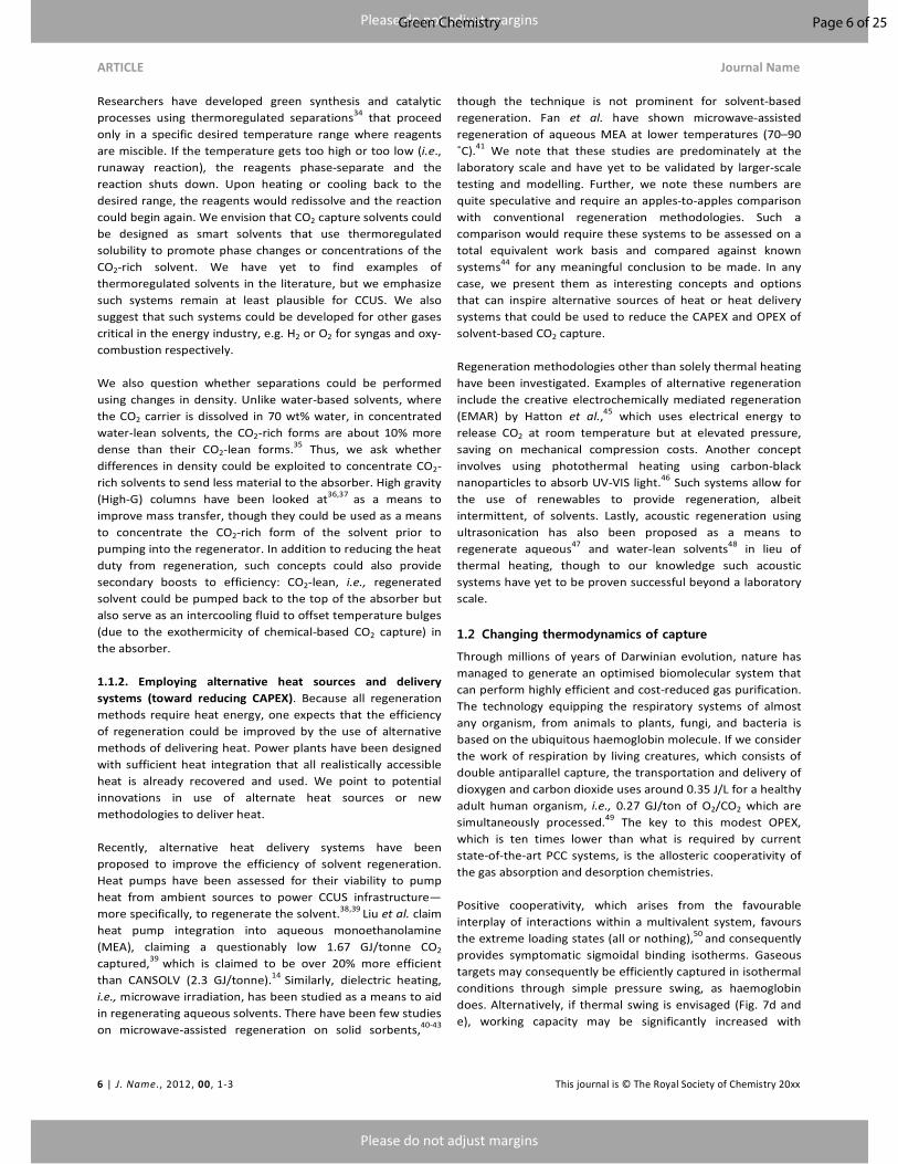
Essentially, the base and acid sites end up playing “hot potato”
with the proton. Having a higher proportion of neutral acid
forms of captured CO2 can reduce the ionicity of the solvent, in
turn reducing viscosity and thereby improving heat exchange.
Fig. 7. Proton and charge localisation affecting chemical and physical properties of CO2 capture systems. (a) Lewis base (green L) and Brønsted base (purple B) of (b) FLPs (green L: Lewis base; purple L: Lewis acid)
Using the principles of GC, we question whether chemists
could fine-tune the equilibria to promote exclusively 100%
neutral capture by reconfiguring the solvation free energies of
acid and ion pairs in solution.
1.3.2. Hot potato #2, electron (de)localisation. If proton
localisation may play a central role in the physical and
chemical features of capture processes based on Brønsted
Lewis base pairs, charge (de)localisation may also be a key for
frustrated Lewis pair-based capture system. Frustrated Lewis
pairs are couples in which steric congestion precludes
neutralisation, which will occur when CO2 is incorporated as a
spacing unit (Fig. 7b).54 This steric mismatch can indeed be
exploited to destabilise the starting mixture. Whereas the
overall thermodynamics and reaction rate was recently proved
to be determined by the strength of the Lewis acids,60
the
electronic features of the Lewis base will greatly affect the
binding/loading capacity, as recently shown by Wang and
colleagues.61
From these statements, it appears that the
optimised design of FLPs with the focus on the electronic
features of each partner may lead to high capacity systems
with low regeneration enthalpies.
1.3.3. Two for the price of one. We have long heard
advertisements proclaiming that “more is better.” Thus, we
question whether there are means to design a capture solvent
that can complex more than one CO2 per active site.
Chemically selective solvents chemically react with CO2 at a
single active site (i.e., degree of alkalinity), making one
equivalent of ions in solution. The challenge, of course, is how
to do this.
Phosphorous and nitrogen are trivalent elements; loading
capacities of nitrogen or phosphorus bases may theoretically
increase when their degree of substitution decreases. One
may argue that the binding of a second CO2 molecule on a
monocarbamate/carbamic acid may be greatly hampered by
its poor nucleophilicity and that the electronic repulsion may
be too strong to obtain a stable 2:1 adduct. Yet synthetic
chemists have proved that diimide can be formed and even
used to capture not one but up to two molecules of CO2 (Fig.
8a). They also have shown that ever-increasingly hindered
amine can be isolated as stable species.62
Early kinetic studies
performed by Monsanto in a perspective of using CO2 as a
green substitute for phosgene for the production of
polyurethanes gathered convergent evidence of the formation
of 2:1 CO2:amine adducts in the presence of bulky nitrogen
bases (Fig. 8b). This finding was later confirmed by in situ
nuclear magnetic resonance analyses performed by Kortunov
et al. at ExxonMobil,63, 64
and raises the question of
protonation state of this pseudo-malonic species whose
carbon-based analogue is known to be stabilised as a
monoanion.
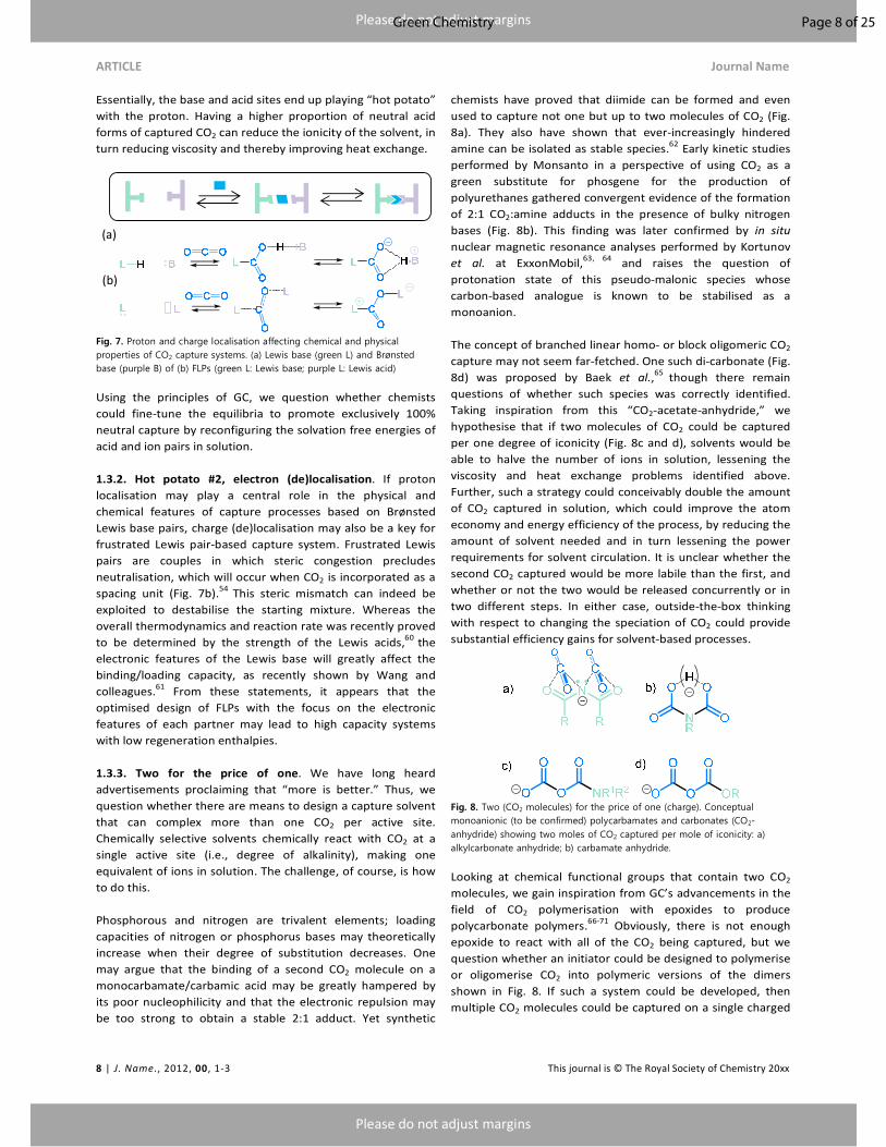
The concept of branched linear homo- or block oligomeric CO2
capture may not seem far-fetched. One such di-carbonate (Fig.
8d) was proposed by Baek et al.,65
though there remain
questions of whether such species was correctly identified.
Taking inspiration from this “CO2-acetate-anhydride,” we
hypothesise that if two molecules of CO2 could be captured
per one degree of iconicity (Fig. 8c and d), solvents would be
able to halve the number of ions in solution, lessening the
viscosity and heat exchange problems identified above.
Further, such a strategy could conceivably double the amount
of CO2 captured in solution, which could improve the atom
economy and energy efficiency of the process, by reducing the
amount of solvent needed and in turn lessening the power
requirements for solvent circulation. It is unclear whether the
second CO2 captured would be more labile than the first, and
whether or not the two would be released concurrently or in
two different steps. In either case, outside-the-box thinking
with respect to changing the speciation of CO2 could provide
substantial efficiency gains for solvent-based processes.
Fig. 8. Two (CO2 molecules) for the price of one (charge). Conceptual monoanionic (to be confirmed) polycarbamates and carbonates (CO2-anhydride) showing two moles of CO2 captured per mole of iconicity: a) alkylcarbonate anhydride; b) carbamate anhydride.
Looking at chemical functional groups that contain two CO2
molecules, we gain inspiration from GC’s advancements in the
field of CO2 polymerisation with epoxides to produce
polycarbonate polymers.66-71
Obviously, there is not enough
epoxide to react with all of the CO2 being captured, but we
question whether an initiator could be designed to polymerise
or oligomerise CO2 into polymeric versions of the dimers
shown in Fig. 8. If such a system could be developed, then
multiple CO2 molecules could be captured on a single charged
(a)
(b)
Page 8 of 25Green Chemistry
Please do not adjust margins
Please do not adjust margins
Journal Name ARTICLE
This journal is © The Royal Society of Chemistry 20xx J. Name., 2013, 00, 1-3 | 9
site, producing oligomeric or polymeric CO2 as a means to
increase capacity.
We finally question whether it is possible to change the
method of CO2 capture by changing the speciation of CO2
when it is captured. CO2 is an “acid gas” and has nearly
unilaterally been captured by means of a Brønsted base. We
ask whether it is possible to fight fire with fire: whether or not
Brønsted acids could be used to chemically react with CO2 and
capture it as carbonic acid. There have been a handful of
studies on the solubility of CO2 in acids72
suggesting CO2 is
sparingly soluble in acids at standard temperature and
pressure, but there are limited studies of solubility at higher
temperatures and pressures. If CO2 can be made more soluble
in acids, the concept may not seem as far-fetched. Consider
that H2SO4 has lower vapour pressure than the amines and
physical solvents currently used, is made cheaply and at the
scales needed for CO2 capture. Further, H2SO4 is inflammable,
and can dissolve SOx and NOx conceivably negating the need
for selective catalytic reduction (SCR) and flue-gas
desulfurisation (FGD) units. Further, from a life-cycle analysis,
concentrated acids would remove some significant problems
of solvent-based processes, primarily solvent degradation,
oxidative and thermal, the formation of carcinogenic
nitrosamines, aerosols and heat-stable salts that deactivate
organic (see basic) capture solvents. The obvious drawback
would be the high acidity of the acid and the challenge and
costs of using acid-tolerant infrastructure, though we note that
all solvent-based capture formulations are themselves highly
corrosive (basic), so the need for any specialised infrastructure
with different corrosion resistance may be a moot point.
1.4 From bio-inspired to biochemical capture
Using biological systems as they have evolved to capture and
convert CO2 is smart and an obvious means to promote CCUS
thus it does not need coverage here. We emphasise that new
areas that focus on methods of rewiring biology for CCUS may
have the most value moving forward.
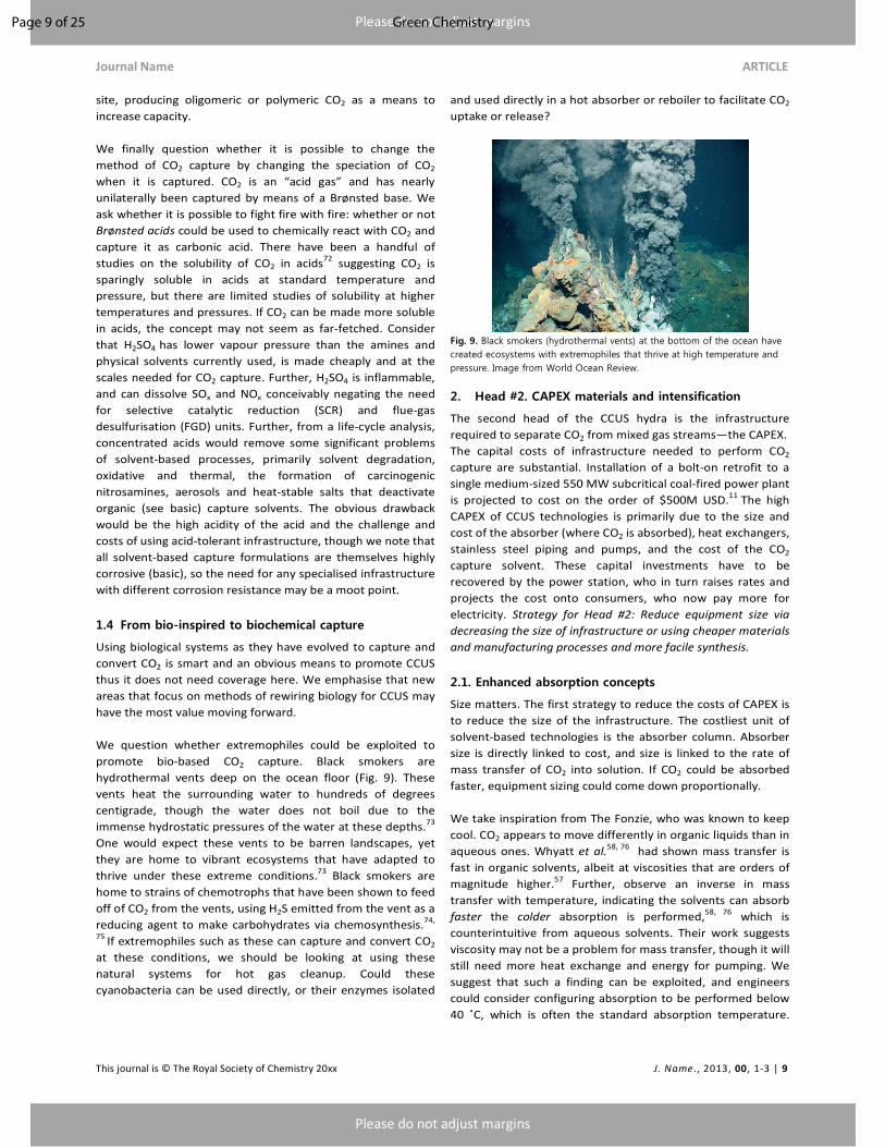
We question whether extremophiles could be exploited to
promote bio-based CO2 capture. Black smokers are
hydrothermal vents deep on the ocean floor (Fig. 9). These
vents heat the surrounding water to hundreds of degrees
centigrade, though the water does not boil due to the
immense hydrostatic pressures of the water at these depths.73
One would expect these vents to be barren landscapes, yet
they are home to vibrant ecosystems that have adapted to
thrive under these extreme conditions.73 Black smokers are
home to strains of chemotrophs that have been shown to feed
off of CO2 from the vents, using H2S emitted from the vent as a
reducing agent to make carbohydrates via chemosynthesis.74,
75 If extremophiles such as these can capture and convert CO2
at these conditions, we should be looking at using these
natural systems for hot gas cleanup. Could these
cyanobacteria can be used directly, or their enzymes isolated
and used directly in a hot absorber or reboiler to facilitate CO2
uptake or release?
Fig. 9. Black smokers (hydrothermal vents) at the bottom of the ocean have created ecosystems with extremophiles that thrive at high temperature and pressure. Image from World Ocean Review.
2. Head #2. CAPEX materials and intensification
The second head of the CCUS hydra is the infrastructure
required to separate CO2 from mixed gas streams—the CAPEX.
The capital costs of infrastructure needed to perform CO2
capture are substantial. Installation of a bolt-on retrofit to a
single medium-sized 550 MW subcritical coal-fired power plant
is projected to cost on the order of $500M USD.11 The high
CAPEX of CCUS technologies is primarily due to the size and
cost of the absorber (where CO2 is absorbed), heat exchangers,
stainless steel piping and pumps, and the cost of the CO2
capture solvent. These capital investments have to be
recovered by the power station, who in turn raises rates and
projects the cost onto consumers, who now pay more for
electricity. Strategy for Head #2: Reduce equipment size via
decreasing the size of infrastructure or using cheaper materials
and manufacturing processes and more facile synthesis.
2.1. Enhanced absorption concepts
Size matters. The first strategy to reduce the costs of CAPEX is
to reduce the size of the infrastructure. The costliest unit of
solvent-based technologies is the absorber column. Absorber
size is directly linked to cost, and size is linked to the rate of
mass transfer of CO2 into solution. If CO2 could be absorbed
faster, equipment sizing could come down proportionally.
We take inspiration from The Fonzie, who was known to keep
cool. CO2 appears to move differently in organic liquids than in
aqueous ones. Whyatt et al.58, 76 had shown mass transfer is
fast in organic solvents, albeit at viscosities that are orders of
magnitude higher.57 Further, observe an inverse in mass
transfer with temperature, indicating the solvents can absorb
faster the colder absorption is performed,58, 76 which is
counterintuitive from aqueous solvents. Their work suggests
viscosity may not be a problem for mass transfer, though it will
still need more heat exchange and energy for pumping. We
suggest that such a finding can be exploited, and engineers
could consider configuring absorption to be performed below
40 ˚C, which is often the standard absorption temperature.
Page 9 of 25 Green Chemistry
Please do not adjust margins
Please do not adjust margins
ARTICLE Journal Name
10 | J. Name., 2012, 00, 1-3 This journal is © The Royal Society of Chemistry 20xx
Running colder could increase the absorption rate due to an
increase in concentration of CO2 physically dissolved in
solution, which would drive liquid kinetics, enabling
smaller/cheaper absorbers and lower solvent circulation rates.
Running colder would require cooling or refrigeration, though
the energy requirements could be offset by a reduced reboiler
duty, because cooling the flue gas would condense water out
of the gas prior to its accumulation in the solvent.35
A second strategy for reducing equipment size via increased
absorption rate is to use catalysis for the absorption process.
There have been recent efforts using biological or chemical
catalysts (inspired by carbonic anhydrase) that tolerate high
temperature, and organic media may help to improve the
kinetics of CO2 capture and release.77, 78 Other strategies have
involved mimicking the active site of the enzyme, using Zn2+
catalysts to enhance the rate of CO2 hydration (CO2 + H2O →
H2CO3) or release.79, 80 While these methodologies have been
shown to increase the rate of absorption, they are unlikely to
provide any further gains as the CO2 uptake will still be mass
transfer limited by the low solubility of CO2 in water.
We postulate that there may be ways to alter the gas/liquid
interface of capture solvents to enable facile diffusion of CO2
into the fluid. Can we change the gas/liquid interfaces to be
more reactive or more gas permeable? Can we take inspiration
from CO2 as a stand-alone green solvent, either as supercritical
CO2 in CO2-expanded liquids81 or organic/aqueous blends
(organic aqueous tunable solvents, or OATS).82 Such studies on
CO2-expanded liquids has shown an increase in solubility or
diffusion of other gases such as H2,81 so we ask whether we
can we apply similar principles of gas-expanded liquids or
other means to promote better/faster mixing or gas
dissolution? Surfactants can be used to change the interfacial
structure and solubility/mixing of reagents at the interface; are
methods available for placing CO2-philic surfactants at the
interface that can be used to favourably dissolve CO2? It has
been shown that there is high solubility of CO2 in the ionic
lattices of ionic liquids.83 We postulate that porous interfaces
or porous liquids could be designed with channels or pores to
favourably solvate and diffuse CO2 more rapidly than in
aqueous solvents. Any of these strategies could be used to
increase mass transfer and, in turn, reduce solvent circulation
rates and equipment size, reducing both CAPEX and OPEX.
2.2. Enhanced desorption concepts
Another strategy to reduce CAPEX would be the use of simpler
regeneration configurations or smaller infrastructure. The
stripper is another large costly unit of infrastructure with
varied configurations having varied costs.84 Other elements of
cost, include the heat exchanger (cross-exchanger), circulation
pumps, and amount of solvent used, can directly affect the
costs of any viable process, though desorption has a smaller
effect on CAPEX.
All commercial first- and second-generation solvent
technologies release CO2 thermally from aqueous solvents by
heating above 100 ˚C with steam from the power plant’s
steam cycle. Similarly, third-generation water-lean solvents
also use thermal regeneration, though regeneration
temperatures have been shown to be as low as 88 ˚C, which
would allow lower-grade heat sources for regeneration,
providing efficiency gains.25, 35
There have been studies of the
costs of different (what we would call conventional) stripper
configurations common to aqueous solvents (e.g., multi-
pressure, split stream, vapour recompression), but the costs
vary within a few percent at best, because each configuration
is at best a slight replumbing of the process. 84 Thus, there is a
need for GC to explore the design and feasibility of innovative
regeneration methodologies with lower costs.
Sadly, we have yet to find something as simplistic as a pipe to
space that can suck all of the CO2 out of the air or a capture
solvent. This however, has not prevented us from envisioning
some avant-garde concepts (Fig. 10) as a means to reduce
CAPEX. As mentioned before, CAPEX reduction on the
desorption side may not come from a new stripper
configuration, but might have to come from inventive
concepts to facilitate CO2 release.
Fig. 10. Advanced desorption concept; space vacuum as inspired by Brooks et al., “Spaceballs,” 1987.
The first concept can simply be the rate at which CO2 can be
stripped from the fluid. We have previously highlighted
attempts to get CO2 into solution faster by means of catalysts,
but there are limited studies on catalytic CO2 release. Leclaire
et al. have recently proposed evaluating the potential use of
carbamates in hydrometallurgy to design sustainable metal
purification processes.85
While the use of oxo- or aminophilic
metals may strongly alter the thermodynamics of the CO2
capture/release chemistry and thereby affect the OPEX, it may
also modify its kinetics for release, in turn potentially shrinking
the size of the stripper. To go a step further, one can imagine
that lean/rich–metal self-sorting may be used for the
concomitant purification of CO2 from flue gas and metals from
waste material, thereby allowing pooling of the CAPEX and
OPEX for convergent CO2 and valuable metal capture.
A second concept to reduce CAPEX could be to improve heat
transfer, thus shrinking the cross-exchanger. Water is a good
Page 10 of 25Green Chemistry
Please do not adjust margins
Please do not adjust margins
Journal Name ARTICLE
This journal is © The Royal Society of Chemistry 20xx J. Name., 2013, 00, 1-3 | 11
conductor of heat, but nearly all third-generation solvent
technologies use organic solvents, which have half the thermal
conductance of water. The lower the rate of thermal
conductance of the solvent, the larger and costlier the cross-
exchanger becomes. As described above, having a metallic-rich
fraction may increase thermal conductance, thus enabling
third-generation solvents to have comparable (potentially
smaller and cheaper) strippers and cross-exchangers to
aqueous amines. If a potential effect on solvent degradation is
also to be expected, metal additives may be a promising track
to envisage facilitated stripping additives and process
configurations.
A third concept of reducing CAPEX would be to coax CO2 out of
solution by manipulating physical conditions in the stripper.
Andarcia proposed the use of “stripping aids” to reduce the
partial pressure of CO2 over the solvent, acting as an artificial
vacuum to coax more CO2 out of solution at a given
temperature.86
This concept is similar to the way steam
strippers work, in that the steam in the stripper reduces the
partial pressure of CO2, forcing it out of solution. In this case,
these volatile stripping aids could act in concert with steam to
reduce the partial pressure of CO2 even more or facilitate a
faster release of CO2 during stripping. Granted, the
introduction of VOCs could hardly be considered green, but we
highlight that the concept could be made greener if the
stripping aid was nontoxic, bio-sourced and nonflammable, as
the aid would be recovered during the CO2 compression step,
where cooling would condense and recover the stripping aid
with any water vapour.
2.3. Innovative and integrated processes
Because CCUS involves both chemistry and engineering, we
highlight the need for innovative integrated processes that
may achieve efficiency or cost gains by inventive CCUS
operations or by using stranded renewable resources that
have no large-scale storage options available.
2.3.1. Turn it up to 11. Solvent-based CO2 capture units are
large pieces of infrastructure that were envisioned to operate
at a constant circulation rate to capture the consistent
emissions of CO2 from coal-fired power plants. This is because
real-time adjustments to change steady-state operation are
difficult and could introduce new risks and potential failure of
the capture unit. The reality is that power plants cycle capacity
to meet demand; thus, the rate of CO2 emissions changes with
the load cycle to the plant. Arce et al. were the first to address
this issue and proposed an innovative process concept of
flexible solvent regeneration to minimise costs of CO2
capture.87
In this study, a 30 wt% MEA solvent was modelled
to intermittently regulate the extent of solvent regeneration to
minimise operational costs. In this study, they adjusted the
lean/rich loading to buffer and adapt to periods of high and
low load. In periods of high power demand, the capture
solvent was allowed to continually increase its rich loading,
allowing more steam to produce power to export to the grid
during peak hours when demand and cost of power are high.
Conversely, in periods of low power demand, the solvent could
then be regenerated to a leaner solvent loading when power is
more abundant, and costs are lower. Further, their modelling
findings suggest efficiency of the plant could be increased by
as much as 10% using this type of flexible approach. We find it
encouraging that flexible operation of a pilot-scale power plant
is feasible in that perturbations in plant operation could be
handled and that power plants could adjust to gradient
changes in lean/rich solvent loading with minimal impact.
2.3.2. Digging deeper. Alternatively, Rochelle18
and Davidson
et al.88
have looked at using geothermal resources for
regenerating amines. Davidson’s study focused on the viability
of direct-use geothermal resources directly under coal-fired
power plants.88
The aim of this study was to see the cost and
energy output for stranded geothermal resources in direct-use
CCUS applications. Hot, compressed water (<150 ˚C) can be
found anywhere in the subsurface pending the depth required
to reach it. These resources are everywhere, though they are
not utilised as the water does not efficiently power an organic
Rankine cycle (ORC) turbine to justify their cost. In this study,
Davidson and team focused on assessing the costs and power
output for using hot, compressed water for direct-use
applications in CCUS infrastructure such as boiler feedwater
preheating or powering a reboiler to regenerate solvents. They
concluded that 550 MW scale subcritical power plants could
use these resources for boiler water preheating, saving 19 MW
of power for boiler feedwater preheating only, requiring
20,441 liters per minute (lpm) of 150 ˚C water at a cost of
$34.7M USD. For comparison, that flow of water would
produce only 9 MW of power in an ORC at a cost of $47.2M
USD ($5.2M/MW). Powering the entire reboiler for MEA could
produce 101 MW of power, though it would require a
prohibitive 265,000 lpm at a cost of $108.6M USD
($1.1M/MW). Third-generation solvents like CO2BOLs,
however, were projected to make 121 MW of power, requiring
a sizable, but not unreasonable, 75,700 lpm to regenerate the
solvent at a cost of only $51.6M USD ($0.42M/MW).88
With the two examples above, we question whether or not
there are other innovative or integrated processes that could
be developed. Another area of need is the compression of CO2;
mechanical compressors consume as much as 12% of loss of
efficiency for a power plant to compress CO2 to a supercritical
state for pumping or sequestration.89, 90
There have been
investigations into varied compression strategies, ranging from
multistage compression with intercooling, compression
combined with liquefaction and more exotic methodologies
such as supersonic shockwave compression.91
Similarly,
Rochelle (UT Austin) has shown that thermal compression of
CO2 requires lower compression work than mechanical
compression and thus a lower total equivalent work needed
for carbon capture.92
The trade-off is the requirement to
regenerate solvents at temperatures above >120 ˚C,
potentially increasing the rate of thermal and oxidative
degradation of the solvent. We question whether there could
Page 11 of 25 Green Chemistry
Please do not adjust margins
Please do not adjust margins
ARTICLE Journal Name
12 | J. Name., 2012, 00, 1-3 This journal is © The Royal Society of Chemistry 20xx
be alternative means of compression, via Hatton’s EMAR
concept,45
or by integration with other chemical or mechanical
processes such as solar-thermal compression or more avante
garde concepts using things like thermoacoustic engines.
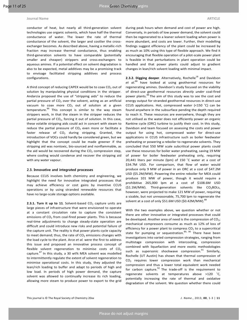
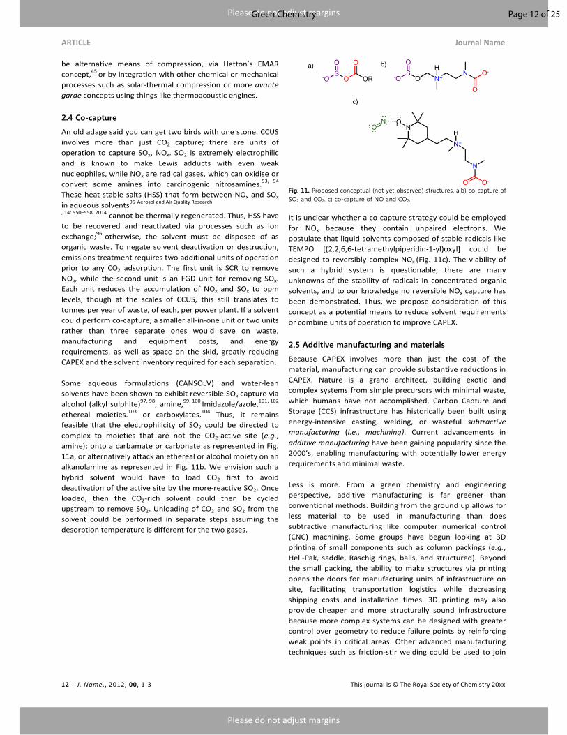
2.4 Co-capture
An old adage said you can get two birds with one stone. CCUS
involves more than just CO2 capture; there are units of
operation to capture SOx, NOx. SO2 is extremely electrophilic
and is known to make Lewis adducts with even weak
nucleophiles, while NOx are radical gases, which can oxidise or
convert some amines into carcinogenic nitrosamines.93, 94
These heat-stable salts (HSS) that form between NOx and SOx
in aqueous solvents95
Aerosol and Air Quality Research
, 14: 550–558, 2014 cannot be thermally regenerated. Thus, HSS have
to be recovered and reactivated via processes such as ion
exchange;96
otherwise, the solvent must be disposed of as
organic waste. To negate solvent deactivation or destruction,
emissions treatment requires two additional units of operation
prior to any CO2 adsorption. The first unit is SCR to remove
NOx, while the second unit is an FGD unit for removing SOx.
Each unit reduces the accumulation of NOx and SOx to ppm
levels, though at the scales of CCUS, this still translates to
tonnes per year of waste, of each, per power plant. If a solvent
could perform co-capture, a smaller all-in-one unit or two units
rather than three separate ones would save on waste,
manufacturing and equipment costs, and energy
requirements, as well as space on the skid, greatly reducing
CAPEX and the solvent inventory required for each separation.
Some aqueous formulations (CANSOLV) and water-lean
solvents have been shown to exhibit reversible SOx capture via
alcohol (alkyl sulphite)97, 98
, amine,99, 100
Imidazole/azole,101, 102
ethereal moieties.103
or carboxylates.104
Thus, it remains
feasible that the electrophilicity of SO2 could be directed to
complex to moieties that are not the CO2-active site (e.g.,
amine); onto a carbamate or carbonate as represented in Fig.
11a, or alternatively attack an ethereal or alcohol moiety on an
alkanolamine as represented in Fig. 11b. We envision such a
hybrid solvent would have to load CO2 first to avoid
deactivation of the active site by the more-reactive SO2. Once
loaded, then the CO2-rich solvent could then be cycled
upstream to remove SO2. Unloading of CO2 and SO2 from the
solvent could be performed in separate steps assuming the
desorption temperature is different for the two gases.
Fig. 11. Proposed conceptual (not yet observed) structures. a,b) co-capture of SO2 and CO2. c) co-capture of NO and CO2.
It is unclear whether a co-capture strategy could be employed
for NOx because they contain unpaired electrons. We
postulate that liquid solvents composed of stable radicals like
TEMPO [(2,2,6,6-tetramethylpiperidin-1-yl)oxyl] could be
designed to reversibly complex NOx (Fig. 11c). The viability of
such a hybrid system is questionable; there are many
unknowns of the stability of radicals in concentrated organic
solvents, and to our knowledge no reversible NOx capture has
been demonstrated. Thus, we propose consideration of this
concept as a potential means to reduce solvent requirements
or combine units of operation to improve CAPEX.
2.5 Additive manufacturing and materials
Because CAPEX involves more than just the cost of the
material, manufacturing can provide substantive reductions in
CAPEX. Nature is a grand architect, building exotic and
complex systems from simple precursors with minimal waste,
which humans have not accomplished. Carbon Capture and
Storage (CCS) infrastructure has historically been built using
energy-intensive casting, welding, or wasteful subtractive
manufacturing (i.e., machining). Current advancements in
additive manufacturing have been gaining popularity since the
2000’s, enabling manufacturing with potentially lower energy
requirements and minimal waste.
Less is more. From a green chemistry and engineering
perspective, additive manufacturing is far greener than
conventional methods. Building from the ground up allows for
less material to be used in manufacturing than does
subtractive manufacturing like computer numerical control
(CNC) machining. Some groups have begun looking at 3D
printing of small components such as column packings (e.g.,
Heli-Pak, saddle, Raschig rings, balls, and structured). Beyond
the small packing, the ability to make structures via printing
opens the doors for manufacturing units of infrastructure on
site, facilitating transportation logistics while decreasing
shipping costs and installation times. 3D printing may also
provide cheaper and more structurally sound infrastructure
because more complex systems can be designed with greater
control over geometry to reduce failure points by reinforcing
weak points in critical areas. Other advanced manufacturing
techniques such as friction-stir welding could be used to join
Page 12 of 25Green Chemistry

Please do not adjust margins
Please do not adjust margins
Journal Name ARTICLE
This journal is © The Royal Society of Chemistry 20xx J. Name., 2013, 00, 1-3 | 13
metals and piping with greater control over weld integrity and
metallurgical properties. Friction-stir welding is also modular
and could be used to manufacture and assemble infrastructure
on site, also reducing costs. Ultimately, we champion
advanced manufacturing as an attractive means to reduce
CAPEX of CCUS infrastructure, assuming larger infrastructure
such as absorber or stripper columns could be printed on site.
Another advantage of additive manufacturing is the ability to
mimic nature and manufacture complex systems that could
not be made with conventional means. With 3D
manufacturing, new exotic packings such as gyroids (Fig. 12a)
can be manufactured. Gyroids, discovered by Schoen, have
been proposed as more efficient packings and heat
exchangers.105
Gyriods are thin and structurally strong,
providing a continuous high surface area packing, with
attractive heat transfer, lower pressure drops and uniform film
thickness.106
Fig. 12. 3D printed infrastructure. a) bi-continuous packing, b) microchannel heat exchanger, c) artificial lung. Images from: https://www.sglgroup.com, GrabCAD Blog, Credit: ThinkStock/XiaoZhi Lim.
3D printing can also be used to manufacture heat exchangers
with microchannels and high surface areas (Fig. 12).
Microchannel heat exchangers are more compact and efficient
than conventional plate-and-frame or tube/shell heat
exchangers, suggesting cost improvements could be gained
with units of operation such as the cross-exchanger. Thinking
further down the road, more complex heat exchangers such as
gyroids can also be used, as their tri-continuous phases could
be configured for cold-rich solvent in one direction, with hot
lean solvent coming in on the other side. Thus, 3D printing
opens new doors for CAPEX reduction if such packing and heat
exchangers could be made at scale.
Gas-to-liquid absorption processes require high gas-liquid
surface to be efficient. The challenge is that surface area has
to be provided by column packings, which provide a nominal
size cost burden. To come back to nature’s choices, to process
the flue gas at flowrates of an average coal-fired plant, given
the pulmonary capacity of human lungs (18 L CO2/h), only 19
m3 (a small removal van) of pulmonary tissue, though
corresponding to an exchange surface area of 25,300 tennis
courts, would be required. Thus, from a cost perspective, any
increases in surface area above current packing geometries
can yield substantive reductions in cost. Researchers are
already starting to create biologically inspired systems to
improve gas/liquid contact with the highest surface area for
getting CO2 into solution (Fig. 12c). Esser-Khan presented one
such example, mimicking avian lungs as more efficient
gas/liquid contactors.107
Such innovative structures had been
considered for years, though they could not be manufactured
before recent advances in additive manufacturing.
Another area for CAPEX reduction is swapping out the
materials used on CCUS infrastructure for cheaper and more
durable materials. All solvent-based processes use some alloy
of corrosion-resistant steel due to the corrosivity of CO2 -
capture fluids. The costs of steel alloys vary widely, with
corrosion-resistant stainless steel far more costly than carbon
steel. Steels primarily corrode due to the formation of carbonic
acid, which is produced when water hydrates CO2.108
All
aqueous solvents require high-cost stainless steel to minimise
corrosion and degradation of process infrastructure, though
water-lean solvents might be able to use lower-grade steels,
enabling considerable cost reductions.109,110
Joe Camp famously said, “Just because something has always
been done a certain way does not necessarily mean it's the
best way.” Along these lines, we ask why steels have to be
used in the first place. If CCUS infrastructure could be made
with something more durable and chemically inert like fibre-
reinforced plastic, costs of infrastructure could come down
substantially. It is our opinion that the only reason steels are
still used is that aqueous solvents cannot wet other surfaces
like plastics because the contact angle is too high. Water-lean
solvents, which are predominately organic, could wet plastics
due to their lower contact angles and surface tensions. Thus,
we propose the use of plastics (preferably biodegradable,
definitely non-halogenated) as a cheaper alternative to steels.
The choice of using plastics in CCUS infrastructure would at
first seem counterintuitive to the principles of GC, though we
highlight that from a cost and life-cycle analysis, the corrosion
of steel releases highly toxic metals like Ni and Cr, which can
end up accumulating in the solvent but also the environment.
We also point out that solvent (MEA) degradation has been
shown by Rochelle and others to be catalysed by metals from
corrosion,111-114
necessitating the use of corrosion inhibitors,
which are costly and not environmentally benign. If steels
could be avoided, solvent lifetime would be increased,
corrosion inhibitors could be avoided, and ultimately the
amount of degradation products that can accumulate in the
environment would be reduced. Using plastics could yield
substantial cost savings as well as some environmental
benefits.
Plastics do have an Achilles’ Heel: while they are cheap and
chemically durable, they are often not biodegradable, and
their environmental impact must be considered. Fortunately,
evolution has given us a new weapon to fight the
accumulation of plastic in the environment: worms!
Researchers have recently discovered bacteria in waxworms
(caterpillars) that have enzymes that can digest chemically
robust plastics such as polyethylene within hours,115, 116
as
compared to the decades it normally takes for plastic to break
down naturally. We envision the use of enzymes such as these
a) b) c)
Page 13 of 25 Green Chemistry

Please do not adjust margins
Please do not adjust margins
ARTICLE Journal Name
14 | J. Name., 2012, 00, 1-3 This journal is © The Royal Society of Chemistry 20xx
to break down spent or old plastic infrastructure after use.
Thus, from a cost perspective, cheaper infrastructure like
plastics will not only reduce the CAPEX of CCUS, but may result
in a lower environmental impact than stainless steels over the
lifetime of a CO2 capture plant (~30 years).
One last concept to reduce CAPEX is to find waste and turn it
into valuable products. Coal combustion produces a myriad of
waste products such as Hg, HCl, NOx and SOx, with the latter
converted to gypsum and sold for use in cement board. There
remains at least some potential for recovery of other by-
products for commercial sale. Consider that stainless steel
piping in CCUS infrastructure corrodes over time, leaching
metals into the capture solvent. CO2-promoted metal
chelation as shown by Leclaire et al.85
could be used to recover
metals from corrosion such as Cr, Ni, and Fe and sell them to
recoup at least some element of cost. Revisiting the acid
capture concept above, HCl,72
NOx, and SOx can be separated
using selective anion exchange membranes, with the acids
being recovered and sold commercially.
3. Head #3. The life cycle of capture solvent synthesis, lifetime, disposal, and environmental effects
The third head of the CCUS hydra entails contradictions that
must be weighed, where we must balance priorities of
whether atom or energy efficiency is more vital or whether
solvent durability undermines biodegradability. Here, we
present the contradictions of solvent development, focusing
on the entire life cycle of the solvent, covering the atom and
energy efficiency, synthesis (reagents and waste), solvent
durability, and cost. Strategy for Head #3: Use the tenets of GC,
after assessing the challenges and contradictions of solvent
development.
3.1. Chemical selection, production
To be or not to be (green)? The first contradiction of solvent
development is the choice of solvent itself. In GC, we gravitate
toward greener solvents such as water, which is cheap,
inflammable, and nontoxic, though water may not be the ideal
solvent for CCUS (Fig. 13). The choice of water as a solvent
would seem to be the greenest option, though CO2 is sparingly
soluble in water.117
unless the pH is basic, where CO2 is
hydrolysed and brought into solution as bicarbonate. Thus, the
only way to get enough CO2 into solution is to add 1˚ and 2˚
amines to either react directly with CO2 to form a carbamate,
or a 3˚ amine which slowly captures CO2 as bicarbonate or
carbonate salt. Aqueous amines have been used since the
1930s13
to capture CO2, representing all commercial first- and
second-generation technologies. One would think that
aqueous formulations are optimal from a GC perspective, yet
these solvents are limiting by corrosion of steel infrastructure
and the sizeable energy inefficiency associated with
regenerating the solvent (boiling and condensing millions of
gallons of water an hour).11
Thus, the first contradiction is
blatantly apparent; water is a cheap and green solvent for
most chemical processes, but the low solubility, corrosion, and
energy-intensive regeneration are limiting in CCUS. For these
reasons, new third-generation solvents are focusing on
reducing water content as a means to improve solubility and
energy efficiency, but to also reduce corrosion at the expense
of being flammable, and costlier. The trade-off that is
occurring in solvent development would at first seem
counterintuitive to GC principles—replacing water with non-
volatile organic chemicals—though we argue that this might
be a necessary evil.
Fig. 13. Solvent selection is a delicate balancing act. Pros and cons of aqueous vs. non-aqueous solvents.
We next highlight the sheer magnitude of solvent needed for
separations: millions of kg of solvent are needed per power
plant! A single 550 MW subcritical coal-fired power plant
circulating MEA is projected to circulate over 4,000,000 kg/h of
solvent, plus solvent makeup rates.11
With thousands of coal-
fired power plants in the world, the amount of solvent needed
for CO2 capture is overwhelming. We highlight the work of
Bara, who first shed light on this bottleneck of chemical
production capacity to manufacture simple solvents.118
Bara
cautions that there is not enough capacity to manufacture
complex solvents, and the only chemical that may be made at
scale is MEA, which is made from commodity chemicals
ethylene oxide (via ethylene) and ammonia. Bara’s analysis
suggests that that more complex solvents, if manufactured,
would promptly breach the world’s top 50 commodity
chemicals.118
One of the biggest challenges for green solvent development is
the synthesis of the solvent. Manufacturing MEA is simple. It is
made from gaseous reagents with no solvent.119
The synthesis
of MEA does produce by-products such as diethanolamine and
triethanolamine, but these by-products have commercial
value.118
Thus, from a manufacturing standpoint, MEA is one
of the greener solvents. More-complex amines have been
studied in recent years, and continue to increase in
Cheap
non-Flammable
Corrosive
Low CO2 solubility
High energy requirement
Toxic
Lower energy requirement
High CO2 solubility
Less-Corrosive
Costly
Flammable
Toxic
Aqueous
Non-Aqueous
Page 14 of 25Green Chemistry

Please do not adjust margins
Please do not adjust margins
Journal Name ARTICLE
This journal is © The Royal Society of Chemistry 20xx J. Name., 2013, 00, 1-3 | 15
complexity, which will require costly multistep synthesis
routes generating substantial amounts of waste and unknown
by-products. Further, the production viability of advanced
solvents is not yet clear, because their chemical precursors are
not yet scaled and there may not be markets for their by-
products.118
Lastly, all of these chemicals are expected to be
synthesised from petrochemical precursors. Thus, there is a
critical need for GC to facilitate the synthesis and scale-up of
carbon capture solvents.
The principles of GC are straightforward on how to tackle this
problem. We anticipate that raw material sourcing can be
provided from either biological or renewable sources such as
biomass, amino acids, or biological sources, rather than
petrochemicals. Chemical synthons such as carbon backbones
and alcohol moieties can be recovered from biomass, whereas
amine functionalities can be recovered from natural sources
like chitosan. We question whether chemical precursors can
be sourced from more avant-garde sources such as municipal
waste streams or industrial waste sources such as agricultural
runoff (which contains amine-rich fertiliser). We also advocate
solvent-free synthesis and avoiding VOCs during
manufacturing as a means to reduce waste. Chemical synthesis
should be designed such that any unavoidable by-products
would be value-added products, providing economic drivers
for their sale rather than disposal as organic waste. Lastly, the
use of catalysts or enzymatic processes would make
manufacturing more atom and energy efficient.
3.2. Lifetime of the solvents/biodegradation
Going the distance. One of the tenets of GC is to use reagents
that are environmentally benign and that can biodegrade,
creating a paradox of solvent durability. The contradiction is
readily apparent, with the challenge of designing a solvent that
shows reduced heat-stable salt formation, durability toward
hydrolysis, heat, and oxidative degradation for thousands of
cycles during operation, yet biodegrades by essentially the
same degradation pathways after use. Because the solvent is
costly, it needs to be durable, and chemical manufacturers are
forced to introduce a mélange of chemical additives such as
antifoaming agents, anti-aerosols, antioxidants, and
anticorrosion agents to keep the OPEX and CAPEX of the
solvent down. Thus, the challenge is, how do we prioritise the
need for durability during use vs. biodegradation after being
released? The easiest solution (pun intended) is to not make as
much waste by minimising chemical degradations, or minimise
fugitive emissions, though these are easier said than done.
We postulate whether a solvent kill-switch could be employed
the moment the solvent or one of its degradation products is
emitted from the CCUS infrastructure (Fig. 14). We envision
the incorporation of chemical moieties that are thermally and
oxidatively stable but unstable to external stimuli (e.g., UV
light) added to solvents, where exposure to natural light could
begin the degradation process or denature them so that they
are no longer toxic.
Fig. 14. In a perfect world, solvents would contain a solvent kill-switch to turn on biodegradation.
Another concept is the use of chemical chelators that complex
with the unwanted and toxic material, chemically converting it
into a biodegradable substance that could be disposed of with
minimal harm to the environment. We take inspiration from
natural gas sweetening, in which highly toxic H2S (lethal at 4
ppm) can be made innocuous after chelation and reaction with
iron chelates or triazine.120
It remains likely that degradation
products could be broken down selectively, as they will have
distinctive functional groups (nitrosamine) that are not
commonly found in nature. While not optimal, chemical
chelats could be designed to complex and passivate
degradation products at emission locations from the plant or
in water tables surrounding the capture unit. We envision that
extremophiles or other exotic bacteria, or fungi could be used
in this process, assuming they might have (or be engineered to
have) enzymes that could break down and chemically digest
any of the degradation products.
3.3. Disposal/recycling to useful products
Circling the drain. Assuming the plant has reached its useful
life span of 30 years and is decommissioning, the next
challenge is what to do with the millions of litres of solvent in
the unit. We cannot burn the spent material, because that is
wasteful, creates emissions, and there are no places to store
millions of litres of flammable solvent. In a perfect world,
spent solvent could be reconstituted or used as a chemical
synthon for value-added products or used as fertiliser, though
to our knowledge, no studies yet exist. Ironically, we have yet
to find the means to make enough solvent (vide supra), yet we
should also be considering methods to deal with spent solvent.
Thus, there is a critical need to decipher how spent solvent
could be recycled or reconstituted into value-added products.
This, of course, is highly dependent on the solvent in question.
We do emphasise that GC can start looking at chemical motifs
common to CO2 capture solvents (e.g., amines, alcohols) that
could be harvested and used as chemical precursors or
reagents for useful products. This has worked with SO2 being
converted to gypsum for cement board. Ideally, the amines
could be made into a type of fertiliser, which would provide an
environmental benefit, though any recycling or reconstitution
Degrade
Durable
Page 15 of 25 Green Chemistry

Please do not adjust margins
Please do not adjust margins
ARTICLE Journal Name
16 | J. Name., 2012, 00, 1-3 This journal is © The Royal Society of Chemistry 20xx
would extend the life cycle of the solvent to not just be a “one
and done.”
4. Head #4. Transportation/storage
There are many reviews on storage and mineralisation, which
by themselves are extensively studied and can justify a review
on their own; thus, this perspective will briefly touch on
alternative concepts that may be areas of focus for green
chemists. CO2 is generated at specific points of emissions,
though utilisation (so far mainly enhanced oil recovery (EOR)
and sequestration sites (mainly saline aquifers) are often
thousands of miles away. How do we handle CO2 to compress
it, move it, and sequester it more efficiently? Head 4, is best
tackled by finding innovative and regional storage options that
minimize transportation.
As such, the transport of CO2 requires costly and inefficient
infrastructure and is emissive. For pipeline transportation
(3100 km; 44.7 Gt of CO2 worldwide) the average estimated
construction cost in the US is about $20K to 30K per inch per
km. In terms of OPEX, for a throughput of >10 million tons per
year, transport cost can be less than US$1–10/ton of CO2 per
100 km.121 Several technologies can be envisaged, depending
on the physical state under which CO2 is transported (liquid,
gaseous or dense phase). Gaseous CO2 is typically compressed
to a pressure above 8 MPa to increase its density, and thereby
make it easier and less costly to transport (by minimising
frictional losses and avoiding installation of booster stations).
The quality of CO2 greatly matters: dry (moisture-free) CO2 is
not corrosive to the carbon-manganese steels customarily
used for pipelines, even if the CO2 contains contaminants such
as oxygen, hydrogen sulphide, and sulphur or nitrogen oxides.
Moisture-containing CO2 is corrosive, and therefore should
require a resistant (at least internally coated) alloy or a
continuous polymer coating. A CO2 pipeline crossing populated
areas should be avoided, and quantitative risk analysis should
be conducted, including maximum H2S content tolerated,
detailed route selection, pressure protection, leak detection
and other design specifications.122
CO2 can also be transported as a liquid in ship, road, or rail
tankers that carry CO2 in insulated tanks at a temperature well
below ambient, and at much lower pressures. Safety and CO2
quality requirements listed previously apply as well to those
types of transportation.
Getting around. Can we move compressed CO2 easier?
Cheaper? To avoid again the stripping step, can we store CO2
in a condensed liquid carrier and pump it, then compress the
liquid, and then regenerate the solvent? This saves on
mechanical compression since the compression is done on a
liquid, not a gas. As mentioned earlier, disruptive stripping
methods are progressively emerging, some of which could fit
in such a scenario. Electrochemical stripping, like in the EMAR
process developed by Hatton at MIT45
where stripping at high
pressure can be done at room temperature, may be envisaged.
Still, there is, of course, the issue of the concentration of CO2
in such rich phases that will potentially be transported. At 8
MPa and 25°C, CO2 has a density of 765 kg/m3, to be
compared with 2,200 and 1,580 kg/m3 for sodium and
ammonium bicarbonate, respectively. CO2-dense adducts that
remain liquids at room temperature and high pressure can
surely be found. The second objection is, of course, the safety:
accidental release and explosive CO2 blow-off is to be avoided.
Many physical and chemical stimuli favouring capture or
release have been reported (see Section 1) and for sure, some
may conversely be used to temporarily, and on demand,
freeze or block the stripping.
Fig. 15. CO2 transportation: what is the most direct route to cut off the emissions? Graphics: Eulalia Claros in EPR 2015, PE 569.031
4.1. Storage/EOR use
Storage and the sustainability, safety and risks. As for
transportation, CO2 to be stored is handled in a compressed
liquid phase. It is generally injected into saline aquifers in a
perspective of carbonate formation under high pressure
conditions. The issues of leakage and seismicity induction
generally raise a strong concern among the populations, and
many countries have excluded on-shore geological storage.
How/where to safely mineralise CO2 and store it? Are there
different mineralisation reactions we can look at? Are there
alternative storage sites or chemical complexing agents? Can
we mineralise directly during capture (by mineral
carbonation),123
and on which substrates? As seashells do, can
we promote precipitation of carbonates in sea water? With
wastewater? Can we use solid waste material from the
mining124
or building125
industries as substrates? Can mineral
carbonation benefit from centuries of expertise in
heterogeneous catalysis and be activated by soluble agents?
As detailed in the next section, mineral carbonation
simultaneously addresses many issues: it is capture and
storage (as solid carbon) without stripping, compression, or
seismicity issues. Yet, it is energy intensive for kinetic reasons
(limiting mass transfer on solid-liquid-gas reactions). Can
amine scrubbing chemistry mediate/catalyse mineral
carbonation?126
Can the injection of solid or liquid captured
CO2 be made practicable? This would require biocompatible
Page 16 of 25Green Chemistry
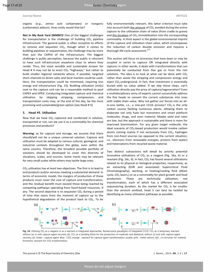
Please do not adjust margins
Please do not adjust margins
Journal Name ARTICLE
This journal is © The Royal Society of Chemistry 20xx J. Name., 2013, 00, 1-3 | 17
organic (e.g., amino acid carbamates) or inorganic
(carbonates) adducts. How costly would that be?
Not In My Back Yard (NIMBY)! One of the biggest challenges
for transportation is the challenge of building CO2 pipeline
infrastructure. The general public is often receptive to efforts
to remove and sequester CO2, though when it comes to
building pipelines or sequestration, the challenge may be more
than just the CAPEX of the infrastructure. The biggest
challenge is public perception, because the public is reluctant
to have such infrastructure anywhere close to where they
reside. Thus, the most sensible and sustainable answer for
Head # 4 may not be to erect CO2 “highways,” but rather to
build smaller regional networks where, if possible, targeted
short channels to direct sales and local markets could be used.
Here, the transportation could be minimised, requiring less
energy and infrastructure (Fig. 15). Building utilisation unit(s)
next to the capture unit can be a reasonable method to pool
CAPEX and OPEX. Conducting integrated capture and chemical
utilisation by skipping stripping, compression, and
transportation costs may, at the end of the day, be the most
promising and sustainable/green option (see Head # 5).
5. Head #5. Utilisation
Now that we have CO2 captured and condensed in solution,
transported or not, can we use it as a commodity for chemical
processes and products?
Warning: as for capture and storage, we assume that there
should/will not be a unique universal solution. Capture and
utilisation must be adapted to various cultural, geological, and
industrial contexts throughout the globe, even within the
same country. Therefore, the broadest possible portfolio of
solutions should be developed to cover this diversity of
situations, scales, and sources. Some tracks may be relevant
for very small scales while others may tackle large ones.
CO2 utilisation has at least two objectives. The first is to lead to
end products and/or services meeting a substantial demand. In
terms of economic model, the margins of production of these
products must cover the cost of capture and transformation,
and the residual benefit must exceed those being reached by
competing pathways operating from fossil-based resources, if
any. The second objective is to sequester CO2 during a period
of time that starts from the moment of capture up to the
hypothetical degradation of the product back to CO2. To be
fully environmentally relevant, this latter criterion must take
into account both the amount of CO2 avoided during the entire
capture to the utilisation chain of value (from cradle to grave)
and the duration of CO2 immobilisation into the corresponding
commodity. A third aspect is the global environmental imprint
of the capture and utilisation chain value, which encompasses
the reduction of carbon dioxide emission and requires a
thorough life-cycle assessment.127
This section will focus on processes that have been or may be
coupled in series to capture OR integrated directly with
capture; in other words, it deals with transformations that can
potentially be conducted from flue gas or from the rich
solutions. The idea is to look at what can be done with CO2
rather than waste the stripping and compression energy and
inject CO2 underground. In fact, that investment is essentially
buried with no value added. If we skip those steps, can’t
utilisation directly pay the price of capture/regeneration? Even
a multidisciplinary army of experts cannot successfully address
the five heads to convert the current substances into ones
with viable chain value. Why not gather our forces into an all-
in-one battle, i.e., a one-pot CCUS process? CO2 is the only
carbon source feeding numerous plants, allowing them to
elaborate not only fuels but monomers and smart platform
molecules, drugs, and even material. Maybe yield and rates
are low, but the approach is sustainable and there is room for
improved biomimetism. For any given target molecule, the
ideal scenario of CO2-based production would involve carbon
atoms coming mainly if not exclusively from CO2, hydrogen
from non-fossil sources (as opposed to the current situation;
i.e., electrons from renewable energies, protons from water)
and heteroatoms from recycled waste material.
Two distinct subsections will detail by priority potential
innovative utilisations of CO2 as a reagent (Fig. 16a, b) or a
reactant (Fig. 16c, d). In fact, CO2 has found several utilisations
related to its physical or biological properties, respectively, as
an extracting (EOR and associated; Supercritical Fluid
Chromatography), working, or heating/cooling fluid (Allam
cycle, CO2 lasers,) or as a commodity for plant growth and food
production. These are technically utilisation, not
transformation, each of which has a different associated
sequestering duration. As the market for CO2 is far smaller
than the amount emitted, head 5 can best be tackled by
identifying as many utilization pathways as possible.
Fig. 16. Utilizing CO2 as a reagent or as a reactant in integrated approaches. Nonexclusive paradigms of integrated CCUS: CO2 as a temporary reactant without (a) or with capture agent recovery (b). CO2 as a building block for the production of materials and feedstock without (c) and with capture agent recovery (d). Green : capture agent. Blue : CO2; orange : reactant for capture agent transformation; purple, pink : metal cations; red : co-nonomer for material formation; reactant for CO2 trnasformation.
(a)
(b)
(c)
(d)
Page 17 of 25 Green Chemistry

Please do not adjust margins
Please do not adjust margins
ARTICLE Journal Name
18 | J. Name., 2012, 00, 1-3 This journal is © The Royal Society of Chemistry 20xx
5.1. CO2 as a reagent
CO2 capture converts blends of neutral capture agents into ion
pairs or hydrogen bonded species. Although reversible, this
coupling phenomenon inevitably alters the reactivity of the
reactants (CO2 and the capture agents) and provides adducts
with new physical and chemical properties. In complement to
trying to produce traditional intermediates or products, whose
widespread use is related to their historical accessibility
through industrial purification and conversion process from
fossil resources, why don’t we produce new (CO2-based only)
molecular systems with new properties?
5.1.1. Physical: Switchable polarity solvents and polymers.
The majority of 3rd
generation solvents may be recycled and
utilized in a myriad of uses as switchable materials or simply as
solvents themselves. Switchable materials are materials that
can serve two purposes, whether as solvents that can switch
between polarity, miscibility, or as functional materials that
can perform multiple functions, minimizing waste, thus
improving atom efficiency.128
Water-lean solvents are in
essence switchable polarity solvents (first identified by Jessop)
as they are low-polarity molecular liquids that react with a
chemical trigger gas, i.e. CO2 to become polar ionic liquids.53
Switchable materials have been identified for various
applications ranging from water-purifications, recycling of
plastics, phase change catalysis, polymers, liquid-liquid
separations and reusable surfactants.128
Water-lean solvents in
their CO2-rich solutions are strongly polar and protic, they can
replace water or ionic liquids, while the lean forms are organic
solvents of medium polarity.
5.1.2. Chemical: CO2 as a thermolabile protecting/modulating
group in synthetic chemistry. CO2 can be used to modulate
the reactivity of Lewis-base reacting species involved in
multistep syntheses and requiring a preliminary protecting
step (Fig. 16a). CO2 may indeed be used as an agent delivering
adducts that are less inert and robust than the
tertbutoxycarbonyl (Boc) and fluoromethyloxyacrbonyl
(Fmoc)-protected analogues. Yet, this masking reaction allows
tuning of the reactivity or the rate of release of the free
substrate to be further transformed. Either in the gaseous or
supercritical form (a few catalytic processes carried out in
scCO2 as the reaction solvent and temporary protecting
group)129
CO2 has started to be used as a green auxiliary to
favour the monoalkylation/acylation of amines130, 131
or to
modulate polymer curing, relying on diamines cross-linking.132
Although the duration of sequestering is low (hours), CO2 may
advantageously replace toxic, highly impacting, or simply
chemical agents produced from nonrenewable carbon
resources. The favoured subsequent transformation of the
capture agent may pay part or all of the energetic price for CO2
stripping. This masking/protecting chemistry consisting in true
capture may be conducted on flue gases and be applied to the
manufacturing of industrial amines and to paint and polymer
curing.
5.1.3. Coordination: capture adduct as metal ligands. Since
adducts generated from CO2 capture are frequently anionic,
they can readily bind oxophilic metal centres.133
When using
binders that display multiples sites, such as polyamine,
polycarbamates are obtained. These species are CO2-sourced
analogues of oxalates, succinates, EDTA, which are chelating or
bridging partners, can be obtained. Therefore, these species
can be valorised for metal extraction in sustainable
hydrometallurgical processes (liquid-liquid134
; liquid-solid85
) in
which thermal stripping can advantageously replace chemical
stripping performed by concentrated acid/base, which
generates high volumes of effluents (Fig. 16b). Given their
composition and structure, the resulting CO2-sourced
organometallic complexes are synthetic analogues of RuBisCO
(Ribulose-1,5-bisphosphate carboxylase/oxygenase), the
famous enzyme performing CO2 fixation through C-C coupling
in the Calvin cycles.135
In this gold-standard system, CO2 is
involved both in the coordination of the reactive metal centre
and as a reactant to perform the C3 → C4 elongation of the
substrate (see next section). It appears that virtually all metal
cations and CO2 capture adducts reported so far can be used
as building blocks to be assembled into molecular complexes
and/or metal-organic frameworks (Fig. 16c) with
unprecedented physical and chemical properties.136, 137
As for alkaline earth carbonate, which results from CO2
capture with the alkaline earth cations–water couple,
integrated capture and self-assembly can, in principle, be
conducted with flue gas. As with a vast majority of complexes
and materials, the linkages within such architectures may be
sensitive to hydrolysis, and in this very case, to heat. Hence,
this approach delivers materials whose stability domain must
be assessed and may be tuned by screening the building blocks
used, the assembly conditions, and the potential post-
processing. Conversely, it may deliver structures that can
potentially be disassembled and whose constituents can/may
be recycled and reassembled on demand. The design of
materials and catalysts whose components can be
replaced/recycled on demand upon specific stimuli certainly
meets the current standards of sustainable development.
Although the volume and duration of CO2 sequestering may be
modest, the infinite scope of accessible structures and
properties allows hope that we can produce architectures with
unique properties and thereby provide temporary utilisations
of CO2 associated with high added values.
5.2. CO2 as a reactant and building block toward fully
CO2-sourced chemicals and materials
The current architecture of the industrial assembly line
yielding fine organic chemicals and polymers relies on a library
of C1 to C4 aliphatic hydrocarbon building blocks and benzene
derivatives. CO2, which is a C1-as synthon or starting material,
has so far mostly led to C1 products (carbon monoxide,
carbonates, formic acid/formates, methanol, methane, urea,
Page 18 of 25Green Chemistry
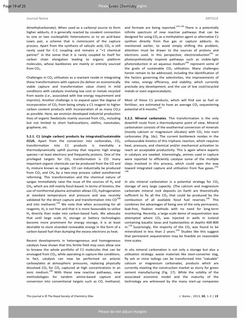
Please do not adjust margins
Please do not adjust margins
Journal Name ARTICLE
This journal is © The Royal Society of Chemistry 20xx J. Name., 2013, 00, 1-3 | 19
dimethylcarbonate). When used as a carbonyl source to form
higher adducts, it is generally reacted by covalent connection
to one or two nucleophilic heteroatoms or to an acid-base
Lewis pair, a scheme that is reminiscent of the capture
process. Apart from the synthesis of salicylic acid, CO2 is still
rarely used for C-C coupling and remains a “+1 chemical
partner” in the sense that it is rarely coupled to itself for
carbon chain elongation leading to organic platform
molecules, whose backbones are mainly or entirely sourced
from CO2.
Challenges in CO2 utilisation as a reactant reside in integrating
these transformations with capture (to deliver an economically
viable capture and transformation value chain) in mild
conditions with catalysts involving low cost or metals recycled
from waste (i.e., associated with low energy requirement and
imprints). Another challenge is to expand upon the degree of
incorporation of CO2 from being simply a C1 reagent to higher
carbon content products with incorporation of as many CO2s
as possible. Here, we envision developed industrial production
lines of organic feedstocks mainly sourced from CO2, including
but not limited to short hydrocarbons, olefins, nanotubes,
graphene, etc.
5.2.1. C1 (single carbon) products by integrated/sustainable
CCUS. Apart from the conversion into carbonates, CO2
transformation into C1 products is inevitably a
thermodynamically uphill journey that requires high energy
species—at least electrons and frequently protons. One of the
privileged targets for CO2 transformation is CO: many
important organic chemicals can be produced from the CO and
H2 mixture known as syngas. CO can industrially be produced
from CO2 and CH4 by a two-step process called autothermal
reforming. This transformation and the chemical nature of
syngas immediately raise the issue of the sources of H2 and
CH4, which are still mainly fossil-based. In terms of kinetics, the
use of nonthermal plasma activation allows CO2 hydrogenation
at standard temperature and pressure and was recently
validated for the direct capture and transformation into CO138
and into methanol.139
We note that when accounting for all
reagents, H2 is not free and that it is more favourable to utilize
H2 directly than make into carbon-based fuels. We advocate
that until large scale H2 storage or battery technologies
become more prominent for energy storage, it is at least
desirable to store stranded renewable energy in the form of a
carbon-based fuel than dumping the excess electrons as heat.
Recent developments in heterogeneous and homogeneous
catalysis have shown that this fertile field may soon allow one
to browse the whole portfolio of C1 molecules that can be
envisaged from CO2, while operating in capture-like conditions.
In fact, catalysis can now be performed on anionic
carboxylates at atmospheric pressures, replacing physically
dissolved CO2 for CO2 captured at high concentrations in an
ionic medium.140
With these new reactive pathways, new
methodologies for tandem amine-based capture and
conversion into conventional targets such as CO, methanol,
and formate are being reported.141-144
There is a potentially
infinite spectrum of new reactive pathways that can be
designed for using CO2 as a methylation agent or alternative C1
synthon directly from flue gas or capture adducts. As
mentioned earlier, to avoid simply shifting the problem,
attention must be drawn to the sources of protons and
electrons used. In this perspective, electroreduction145
or
photosynthetically inspired pathways such as visible-light
photoreduction in an aqueous medium146
represent some of
the grails of sustainable CO2 utilisation. Many challenges
herein remain to be addressed, including the identification of
the factors governing the selectivities, the improvements of
the rates, energy efficiency, and stability, which currently
preclude any development, and the use of low cost/recycled
metals or even organocatalysts.
Most of these C1 products, which will find use as fuel or
fertiliser, are estimated to have an average CO2 sequestering
potential of 6 months.147
5.2.2. Mineral carbonates. This transformation is the only
downhill route from a thermodynamic point of view. Mineral
carbonation consists of the exothermal conversion of minerals
(mostly calcium or magnesium silicates) with CO2 into inert
carbonates (Fig. 16c). The current bottleneck resides in the
unfavourable kinetics of this triphasic reaction, which requires
heat, pressure, and chemical and/or mechanical activation to
reach an acceptable productivity. This is again where experts
in catalysis are needed. Interestingly, amines used in capture
were reported to efficiently catalyse some of the multiple
steps involved in this process, which could open the way
toward integrated capture and utilisation from flue gases.126,
148
In situ mineral carbonation is a potential strategy for CO2
storage of very large capacity. (The calcium and magnesium
carbonate mineral rock deposits on Earth are theoretically
sufficient to fix all the CO2 that could be produced by the
combustion of all available fossil fuel reserves.149
This
combines the advantages of being one of the only permanent,
leak-free, fixation methods with no need for long-term
monitoring. Recently, a large-scale demo of sequestration was
attempted where CO2 was injected in wells in Iceland
containing basaltic lavas and hyaloclastites at depths 400-800
m.150
Surprisingly, the majority of the CO2 was found to be
mineralized in less than 2 years.150
Studies like this suggest
that permanent sequestration may be feasible on reasonable
time scales.
In situ mineral carbonation is not only a storage but also a
utilisation strategy: waste materials like steel-converter slag,
fly ash or mine tailings can be transformed into “valuable”
calcium or magnesium carbonates, products which are
currently meeting the construction market as slurry for green
cement manufacturing (Fig. 17). While the solidity of the
associated economic model and the maturity of the
technology are witnessed by the many start-up companies
Page 19 of 25 Green Chemistry
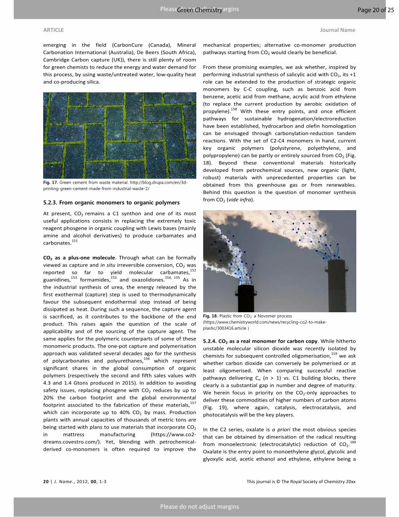
Please do not adjust margins
Please do not adjust margins
ARTICLE Journal Name
20 | J. Name., 2012, 00, 1-3 This journal is © The Royal Society of Chemistry 20xx
emerging in the field (CarbonCure (Canada), Mineral
Carbonation International (Australia), De Beers (South Africa),
Cambridge Carbon capture (UK)), there is still plenty of room
for green chemists to reduce the energy and water demand for
this process, by using waste/untreated water, low-quality heat
and co-producing silica.
Fig. 17. Green cement from waste material. http://blog.drupa.com/en/3d-printing-green-cement-made-from-industrial-waste-2/
5.2.3. From organic monomers to organic polymers
At present, CO2 remains a C1 synthon and one of its most
useful applications consists in replacing the extremely toxic
reagent phosgene in organic coupling with Lewis bases (mainly
amine and alcohol derivatives) to produce carbamates and
carbonates.151
CO2 as a plus-one molecule. Through what can be formally
viewed as capture and in situ irreversible conversion, CO2 was
reported so far to yield molecular carbamates,152
guanidines,153
formamides,153
and oxazolidones.154, 155
As in
the industrial synthesis of urea, the energy released by the
first exothermal (capture) step is used to thermodynamically
favour the subsequent endothermal step instead of being
dissipated as heat. During such a sequence, the capture agent
is sacrificed, as it contributes to the backbone of the end
product. This raises again the question of the scale of
applicability and of the sourcing of the capture agent. The
same applies for the polymeric counterparts of some of these
monomeric products. The one-pot capture and polymerisation
approach was validated several decades ago for the synthesis
of polycarbonates and polyurethanes,156
which represent
significant shares in the global consumption of organic
polymers (respectively the second and fifth sales values with
4.3 and 1.4 Gtons produced in 2015). In addition to avoiding
safety issues, replacing phosgene with CO2 reduces by up to
20% the carbon footprint and the global environmental
footprint associated to the fabrication of these materials,157
which can incorporate up to 40% CO2 by mass. Production
plants with annual capacities of thousands of metric tons are
being started with plans to use materials that incorporate CO2
in mattress manufacturing (https://www.co2-
dreams.covestro.com/). Yet, blending with petrochemical-
derived co-monomers is often required to improve the
mechanical properties; alternative co-monomer production
pathways starting from CO2 would clearly be beneficial.
From these promising examples, we ask whether, inspired by
performing industrial synthesis of salicylic acid with CO2, its +1
role can be extended to the production of strategic organic
monomers by C-C coupling, such as benzoic acid from
benzene, acetic acid from methane, acrylic acid from ethylene
(to replace the current production by aerobic oxidation of
propylene).158
With these entry points, and once efficient
pathways for sustainable hydrogenation/electroreduction
have been established, hydrocarbon and olefin homologation
can be envisaged through carbonylation-reduction tandem
reactions. With the set of C2-C4 monomers in hand, current
key organic polymers (polystyrene, polyethylene, and
polypropylene) can be partly or entirely sourced from CO2 (Fig.
18). Beyond these conventional materials historically
developed from petrochemical sources, new organic (light,
robust) materials with unprecedented properties can be
obtained from this greenhouse gas or from renewables.
Behind this question is the question of monomer synthesis
from CO2 (vide infra).
Fig. 18. Plastic from CO2: a Novomer process (https://www.chemistryworld.com/news/recycling-co2-to-make-plastic/3003416.article )
5.2.4. CO2 as a real monomer for carbon copy. While hitherto
unstable molecular silicon dioxide was recently isolated by
chemists for subsequent controlled oligomerisation,159
we ask
whether carbon dioxide can conversely be polymerised or at
least oligomerised. When comparing successful reactive
pathways delivering Cn (n > 1) vs. C1 building blocks, there
clearly is a substantial gap in number and degree of maturity.
We herein focus in priority on the CO2-only approaches to
deliver these commodities of higher numbers of carbon atoms
(Fig. 19), where again, catalysis, electrocatalysis, and
photocatalysis will be the key players.
In the C2 series, oxalate is a priori the most obvious species
that can be obtained by dimerisation of the radical resulting
from monoelectronic (electrocatalytic) reduction of CO2.160
Oxalate is the entry point to monoethylene glycol, glycolic and
glyoxylic acid, acetic ethanol and ethylene, ethylene being a
Page 20 of 25Green Chemistry

Please do not adjust margins
Please do not adjust margins
Journal Name ARTICLE
This journal is © The Royal Society of Chemistry 20xx J. Name., 2013, 00, 1-3 | 21
key monomer for the production of PET (polyethylene
terepthalate, Fig. 18), which is currently targeted by a joint
venture between Coca-Cola and Liquid Light (acquired by
Avantium).
Looking again at what nature has succeeded in developing
through millennia of Darwinian selection and evolution, Moran
has recently161
managed to mimic the acetyl-CoA pathway of
CO2 fixation (one of the six known to date), in which native
metals provide electrons to reduce CO2 into acetate and
pyruvate (with protons coming from water). Can the five other
natural pathways be mimicked, simplified, and developed by
chemical or biochemical approaches (see next paragraph)
together with totally new artificial ones? Can they operate at
standard temperature and pressure, and reach acceptable
levels of productivity for industrial development?
Fig. 19. Carbon copy: oligomerisation of CO2-reduced species. http://www.brainlesstales.com/2013-04-15/carbon-copy
Beyond C1 products, (photo)electrochemists are also starting
to report catalytic systems (copper-based, mainly162) yielding
as major C2 adducts ethanol and ethylene,163 which are the
workhorses of petrochemical companies. The number of
electron transfer steps and intermediates is growing
exponentially with the number of carbon atoms to be linked
within the chain to be produced, yielding complex mixtures.
The lack of selectivity of these catalytic processes is often
perceived as a barely surmountable challenge, which may
prevent any future upscaling and technology transfer.
If effort shall remain focused on energy efficiency and
resource management, we suggest again to envisage the
design of multidisciplinary integrated processes to overcome
this issue of selectivity and propose innovative solutions. From
a historical and industrial point of view, such mixtures are
crude CO2-based oil, which may be processed by mature
refining technologies. Therefore, tandem conversion or
conversion/purification approaches should be explored with
priority. This suggestion is inspired by recent breakthroughs
reporting that coupled chemical (bio)catalytic transformations
allowed to sequentially perform CO2 activation into C1
intermediates followed by in situ coupling into C2-C4 olefins164,
165 or alcohols.
166 In fact, these emerging multistep cascades
are the embryonic analogues of the metabolic cycles designed
by nature to produce the organic molecules of life from CO2.
The fields of possibility in the design of new man-made cycles
is almost infinite, ranging from fully biochemical, such as the
artificial Calvin-like cycle,167
to purely chemical, with the
production of C4–C8 Gasoline from CO2 and H2 through iron-
based catalysis.168
On the way to produce crude oil from CO2, one challenge
remains fully open and to be addressed by these new
“chemobolic” cycles: the production of benzene rings from
CO2. So far, triazine is the only aromatic adduct whose
conjugated backbone is produced from CO2 though the
trimerisation of CO2-based urea. Yet, pure carbon-based
materials, such as the nanofibers widely used in automotive
and aviation construction169 and multiwalled nanotubes used
for water filtration systems, or as constituents to produce
conducting polymers and battery electrodes, recently proved
to be accessible from CO2.170 Remarkably, these recent reports
illustrate how fertile the integrative system engineering
approach can be, opening the way toward either concomitant
valorisation/recycling of metal-slags or renewable energy
storage (Fig. 20).171 If none of these innovative CCUS pathways
was so far attempted directly from flue gas or capture adducts,
which remains a necessity to design an economically viable
CCUS value chain, there is no doubt that this challenge will
soon be addressed by similar multidisciplinary and integrated
approaches.
Fig. 20. A battery-inspired strategy for carbon fixation. https://phys.org/news/2017-08-battery-inspired-strategy-carbon-fixation.html
Conclusions
Herein we issued an academic and technological “call to arms”
for GC and green engineering to address the complexity and
the magnitude of CCUS. We presented CCUS as a five-headed
hydra with many complexities and challenges that need to
Page 21 of 25 Green Chemistry

Please do not adjust margins
Please do not adjust margins
ARTICLE Journal Name
22 | J. Name., 2012, 00, 1-3 This journal is © The Royal Society of Chemistry 20xx
collectively be addressed to make CCUS a reality. Armed with
the principles of GC and engineering, we emphasise that CCUS
is not an unsolvable problem; rather, the problem is a mélange
of energy, infrastructure, environmental impact, and time that
must be considered equally. In this perspective, we highlighted
challenges for all aspects of CCUS, identifying what has or has
not been attempted, while also identifying swatches of white
space and potential avant-garde concepts in hopes of fostering
innovation or at least stoke conversation on the needs and
focus areas to address this challenge.
We ask the research community to take heed and take up
arms. We encourage the community to reach out to colleagues
in adjacent fields to build synergistic programmes and efforts
that can tackle the magnitude and complexity of this
challenge. GC has made many processes and chemicals
greener while providing some semblance of an economic
driver; there remains no reason why this cannot be the case
with CCUS. If we all take up arms and work together then
there is no limit to the powers of GC to address any current or
future challenges that humanity may face.
Thank you for your audience and we hope that you may join us
on this journey. Sincerely, Julien Leclaire and David J.
Heldebrant.
Acknowledgements
DJH would like to acknowledge the United States Department
of Energy’s (DOE’s) Office of Science, Basic Energy Sciences,
Early Career Research Program FWP 67038 for funding. Pacific
Northwest National Laboratory is proudly operated by Battelle
for the U. S. DOE. JL would like to acknowledge the French
Agency for the Environment and Energy Management
(ADEME) and the LABEX iMUST (ANR-10-LABX-0064) of
Université de Lyon within the program “Investissements
d’Avenir” (ANR-11-IDEX-0007) operated by the French
National Research Agency (ANR) for funding.
Notes and references
1. P. T. Anastas, Warner, J. C. , Green Chemistry: Theory and
Practice, Oxford University Press, New York, 1998. 2. P. T. Anastas and J. B. Zimmerman, Env. Sci. and Tech.,
2003, 37, 94A-101A. 3. David S. Sholl and R. P. Lively, Nature 2016, 532, 435–437. 4. GCP, Global Carbon Budget 2016, ,
http://www.globalcarbonproject.org/carbonbudget/16/files/GCP_CarbonBudget_2016.pdf).
5. Journal, 2014. 6. COP21 Paris Agreement, ,
http://ec.europa.eu/clima/policies/international/negotiations/paris/index_en.htm).
7. M. Bui, C. S. Adjiman, A. Bardow, E. J. Anthony, A. Boston, S. Brown, P. S. Fennell, S. Fuss, A. Galindo, L. A. Hackett, J. P. Hallett, H. J. Herzog, G. Jackson, J. Kemper, S. Krevor, G.
C. Maitland, M. Matuszewski, I. S. Metcalfe, C. Petit, G. Puxty, J. Reimer, D. M. Reiner, E. S. Rubin, S. A. Scott, N. Shah, B. Smit, J. P. M. Trusler, P. Webley, J. Wilcox and N. M. Dowell, Energy Environ. Sci., 2018, 11, 1062—1176.
8. S. Zhao, P. H.M.Feron, L. Deng, E. Favre, E. Chobanon, S. Yan, J. Hou, V. Chen and H. Qi, Journal of Membrane
Science, 2016, 511, 180-206. 9. S.-Y. Lee and S.-J. Park, Journal of Industrial and
Engineering Chemistry 2015, 23, 1-11. 10. D. W. Keith, G. Holmes, D. S. Angelo and K. Heidel, Joule,
2018, DOI: https://doi.org/10.1016/j.joule.2018.05.006. 11. N. E. T. Laboratory, Journal, July 6, 2016, 1. 12. https://www.power-technology.com/projects/taichung/). 13. US Pat., U.S. Patent 1,783,901, 1930. 14. A.Singhand and K. S. ́ephenne, Energy Procedia, 2014, 63,
1678–1685. 15. Y.-J. Lin, E. Chen and G. T. Rochelle, Faraday Discuss.,
2016, 192, 37-58. 16. P. M. Mathias, Fluid Phase Equilib., 2014, 362, 102-107. 17. P. M. Mathias, S. Reddy, A. Smith and K. Afshar, Int. J.
Greenh. Gas Control, 2013, 19, 262-270. 18. D. H. Van Wagener, A. Gupta, G. T. Rochelle and S. L.
Bryant, Oil Gas Sci. Technol. – Rev. IFP Energies nouvelles, 2014, 69, 1105-1119.
19. T. Madan, D. H. Van Wagener, E. Chen and G. T. Rochelle, Energy Procedia, 2013, 37, 386-399.
20. M. S. Walters, R. H. Dunia, T. F. Edgar and G. T. Rochelle, Energy Procedia, 2013, 37, 2133-2144.
21. S. Seo, L. D. Simoni, M. Ma, M. A. DeSilva, Y. Huang, M. A. Stadtherr and J. F. Brennecke, Energy Fuels, 2014, 28, 5968-5977.
22. J. Septavaux, G. Germain and J. Leclaire, Acc. Chem. Res. , 2017, 50, 1692-1701.
23. E. Grunwald and C. Steel, J. Am. Chem. Soc., 1995, 117, 5687–5692.
24. E. A. v. Nierop, S. Hormoz, K. Z. House and M. J. Aziz, Energy Procedia, 2011, 1783–1790.
25. P. M. Mathias, K. Afshar, F. Zheng, M. D. Bearden, C. J. Freeman, T. Andrea, P. K. Koech, I. Kutnyakov, A. Zwoster, A. R. Smith, P. G. Jessop, O. G. Nik and D. J. Heldebrant, Energy Environ. Sci., 2013, 6, 2233-2242.
26. R. J. Perry, B. R. Wood, S. Genovese, M. J. O’Brien, T. Westendorf, M. L. Meketa, R. Farnum, J. McDermott, I. Sultanova, T. M. Perry, R.-K. Vipperla, L. A. Wichmann, R. M. Enick, L. Hong and D. Tapriyal, Energy Fuels, 2012, 26, 2528-2538.
27. T. Zhao, B. Guo, Q. Li, F. Sha, F. Zhang and J. Zhang, Energy
Fuels, 2016, 30, 6555-6560. 28. X. Wang, N. G. Akhmedov, D. Hopkinson, J. Hoffman, Y.
Duan, A. Egbebi, K. Resnik and B. Li, Appl. Energy, 2016, 161, 41-47.
29. D. Malhotra, J. P. Page, M. E. Bowden, A. Karkamkar, D. J. Heldebrant, V.-A. Glezakou, R. Rousseau and P. K. Koech, Ind. Eng. Chem. Res., 2017, 56, 7534-7540.
30. P. Broutin, P. Briot, S. Ehlers and A. Kather, Energy
Procedia, 2017, 114, 2561–2572. 31. D. J. Heldebrant, P. K. Koech, V.-A. Glezakou, R. Rousseau,
D. Malhotra and D. C. Cantu, Chem. Rev. , 2017, 117, 9594−9624.
32. L. M. Rossi, N. J. S. Costa, F. P. Silvaa and R. Wojcieszaka, Green Chem., 2014, 16, 2906-2933.
Page 22 of 25Green Chemistry
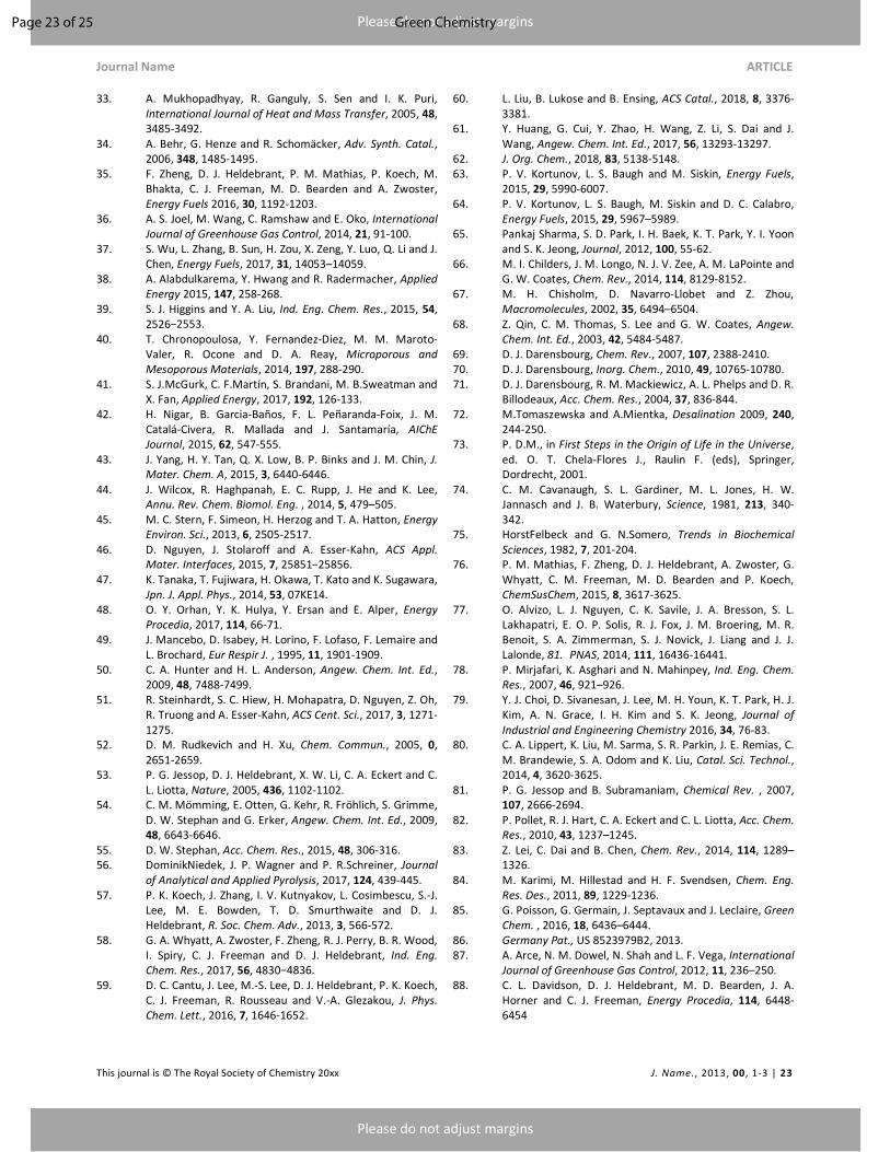
Please do not adjust margins
Please do not adjust margins
Journal Name ARTICLE
This journal is © The Royal Society of Chemistry 20xx J. Name., 2013, 00, 1-3 | 23
33. A. Mukhopadhyay, R. Ganguly, S. Sen and I. K. Puri, International Journal of Heat and Mass Transfer, 2005, 48, 3485-3492.
34. A. Behr, G. Henze and R. Schomäcker, Adv. Synth. Catal., 2006, 348, 1485-1495.
35. F. Zheng, D. J. Heldebrant, P. M. Mathias, P. Koech, M. Bhakta, C. J. Freeman, M. D. Bearden and A. Zwoster, Energy Fuels 2016, 30, 1192-1203.
36. A. S. Joel, M. Wang, C. Ramshaw and E. Oko, International
Journal of Greenhouse Gas Control, 2014, 21, 91-100. 37. S. Wu, L. Zhang, B. Sun, H. Zou, X. Zeng, Y. Luo, Q. Li and J.
Chen, Energy Fuels, 2017, 31, 14053–14059. 38. A. Alabdulkarema, Y. Hwang and R. Radermacher, Applied
Energy 2015, 147, 258-268. 39. S. J. Higgins and Y. A. Liu, Ind. Eng. Chem. Res., 2015, 54,
2526−2553. 40. T. Chronopoulosa, Y. Fernandez-Diez, M. M. Maroto-
Valer, R. Ocone and D. A. Reay, Microporous and
Mesoporous Materials, 2014, 197, 288-290. 41. S. J.McGurk, C. F.Martín, S. Brandani, M. B.Sweatman and
X. Fan, Applied Energy, 2017, 192, 126-133. 42. H. Nigar, B. Garcia-Baños, F. L. Peñaranda-Foix, J. M.
Catalá-Civera, R. Mallada and J. Santamaría, AIChE
Journal, 2015, 62, 547-555. 43. J. Yang, H. Y. Tan, Q. X. Low, B. P. Binks and J. M. Chin, J.
Mater. Chem. A, 2015, 3, 6440-6446. 44. J. Wilcox, R. Haghpanah, E. C. Rupp, J. He and K. Lee,
Annu. Rev. Chem. Biomol. Eng. , 2014, 5, 479–505. 45. M. C. Stern, F. Simeon, H. Herzog and T. A. Hatton, Energy
Environ. Sci., 2013, 6, 2505-2517. 46. D. Nguyen, J. Stolaroff and A. Esser-Kahn, ACS Appl.
Mater. Interfaces, 2015, 7, 25851−25856. 47. K. Tanaka, T. Fujiwara, H. Okawa, T. Kato and K. Sugawara,
Jpn. J. Appl. Phys., 2014, 53, 07KE14. 48. O. Y. Orhan, Y. K. Hulya, Y. Ersan and E. Alper, Energy
Procedia, 2017, 114, 66-71. 49. J. Mancebo, D. Isabey, H. Lorino, F. Lofaso, F. Lemaire and
L. Brochard, Eur Respir J. , 1995, 11, 1901-1909. 50. C. A. Hunter and H. L. Anderson, Angew. Chem. Int. Ed.,
2009, 48, 7488-7499. 51. R. Steinhardt, S. C. Hiew, H. Mohapatra, D. Nguyen, Z. Oh,
R. Truong and A. Esser-Kahn, ACS Cent. Sci., 2017, 3, 1271-1275.
52. D. M. Rudkevich and H. Xu, Chem. Commun., 2005, 0, 2651-2659.
53. P. G. Jessop, D. J. Heldebrant, X. W. Li, C. A. Eckert and C. L. Liotta, Nature, 2005, 436, 1102-1102.
54. C. M. Mömming, E. Otten, G. Kehr, R. Fröhlich, S. Grimme, D. W. Stephan and G. Erker, Angew. Chem. Int. Ed., 2009, 48, 6643-6646.
55. D. W. Stephan, Acc. Chem. Res., 2015, 48, 306-316. 56. DominikNiedek, J. P. Wagner and P. R.Schreiner, Journal
of Analytical and Applied Pyrolysis, 2017, 124, 439-445. 57. P. K. Koech, J. Zhang, I. V. Kutnyakov, L. Cosimbescu, S.-J.
Lee, M. E. Bowden, T. D. Smurthwaite and D. J. Heldebrant, R. Soc. Chem. Adv., 2013, 3, 566-572.
58. G. A. Whyatt, A. Zwoster, F. Zheng, R. J. Perry, B. R. Wood, I. Spiry, C. J. Freeman and D. J. Heldebrant, Ind. Eng.
Chem. Res., 2017, 56, 4830−4836. 59. D. C. Cantu, J. Lee, M.-S. Lee, D. J. Heldebrant, P. K. Koech,
C. J. Freeman, R. Rousseau and V.-A. Glezakou, J. Phys.
Chem. Lett., 2016, 7, 1646-1652.
60. L. Liu, B. Lukose and B. Ensing, ACS Catal., 2018, 8, 3376-3381.
61. Y. Huang, G. Cui, Y. Zhao, H. Wang, Z. Li, S. Dai and J. Wang, Angew. Chem. Int. Ed., 2017, 56, 13293-13297.
62. J. Org. Chem., 2018, 83, 5138-5148. 63. P. V. Kortunov, L. S. Baugh and M. Siskin, Energy Fuels,
2015, 29, 5990-6007. 64. P. V. Kortunov, L. S. Baugh, M. Siskin and D. C. Calabro,
Energy Fuels, 2015, 29, 5967–5989. 65. Pankaj Sharma, S. D. Park, I. H. Baek, K. T. Park, Y. I. Yoon
and S. K. Jeong, Journal, 2012, 100, 55-62. 66. M. I. Childers, J. M. Longo, N. J. V. Zee, A. M. LaPointe and
G. W. Coates, Chem. Rev., 2014, 114, 8129-8152. 67. M. H. Chisholm, D. Navarro-Llobet and Z. Zhou,
Macromolecules, 2002, 35, 6494–6504. 68. Z. Qin, C. M. Thomas, S. Lee and G. W. Coates, Angew.
Chem. Int. Ed., 2003, 42, 5484-5487. 69. D. J. Darensbourg, Chem. Rev., 2007, 107, 2388-2410. 70. D. J. Darensbourg, Inorg. Chem., 2010, 49, 10765-10780. 71. D. J. Darensbourg, R. M. Mackiewicz, A. L. Phelps and D. R.
Billodeaux, Acc. Chem. Res., 2004, 37, 836-844. 72. M.Tomaszewska and A.Mientka, Desalination 2009, 240,
244-250. 73. P. D.M., in First Steps in the Origin of Life in the Universe,
ed. O. T. Chela-Flores J., Raulin F. (eds), Springer, Dordrecht, 2001.
74. C. M. Cavanaugh, S. L. Gardiner, M. L. Jones, H. W. Jannasch and J. B. Waterbury, Science, 1981, 213, 340-342.
75. HorstFelbeck and G. N.Somero, Trends in Biochemical
Sciences, 1982, 7, 201-204. 76. P. M. Mathias, F. Zheng, D. J. Heldebrant, A. Zwoster, G.
Whyatt, C. M. Freeman, M. D. Bearden and P. Koech, ChemSusChem, 2015, 8, 3617-3625.
77. O. Alvizo, L. J. Nguyen, C. K. Savile, J. A. Bresson, S. L. Lakhapatri, E. O. P. Solis, R. J. Fox, J. M. Broering, M. R. Benoit, S. A. Zimmerman, S. J. Novick, J. Liang and J. J. Lalonde, 81. PNAS, 2014, 111, 16436-16441.
78. P. Mirjafari, K. Asghari and N. Mahinpey, Ind. Eng. Chem.
Res., 2007, 46, 921–926. 79. Y. J. Choi, D. Sivanesan, J. Lee, M. H. Youn, K. T. Park, H. J.
Kim, A. N. Grace, I. H. Kim and S. K. Jeong, Journal of
Industrial and Engineering Chemistry 2016, 34, 76-83. 80. C. A. Lippert, K. Liu, M. Sarma, S. R. Parkin, J. E. Remias, C.
M. Brandewie, S. A. Odom and K. Liu, Catal. Sci. Technol., 2014, 4, 3620-3625.
81. P. G. Jessop and B. Subramaniam, Chemical Rev. , 2007, 107, 2666-2694.
82. P. Pollet, R. J. Hart, C. A. Eckert and C. L. Liotta, Acc. Chem.
Res., 2010, 43, 1237–1245. 83. Z. Lei, C. Dai and B. Chen, Chem. Rev., 2014, 114, 1289–
1326. 84. M. Karimi, M. Hillestad and H. F. Svendsen, Chem. Eng.
Res. Des., 2011, 89, 1229-1236. 85. G. Poisson, G. Germain, J. Septavaux and J. Leclaire, Green
Chem. , 2016, 18, 6436–6444. 86. Germany Pat., US 8523979B2, 2013. 87. A. Arce, N. M. Dowel, N. Shah and L. F. Vega, International
Journal of Greenhouse Gas Control, 2012, 11, 236–250. 88. C. L. Davidson, D. J. Heldebrant, M. D. Bearden, J. A.
Horner and C. J. Freeman, Energy Procedia, 114, 6448-6454
Page 23 of 25 Green Chemistry
Please do not adjust margins
Please do not adjust margins
ARTICLE Journal Name
24 | J. Name., 2012, 00, 1-3 This journal is © The Royal Society of Chemistry 20xx
89. J. J. Moore, A. Lerche, H. Delgado, T. Allison and J. Pacheco, Proceedings of the Fortieth Turbomachinery
Symposium, 2011, DOI: https://doi.org/10.21423/R1S65C, 107-120.
90. PengPei, K. Barse, A. J.Gil and J. Nasah, Int. J. Greenh. Gas
Control, 2014, 30, 86-96. 91. A. Witkowski, A. Rusin, M. Majkut, S. Rulik and K.
Stolecka, Energy Convers. Manage., 2013, 76, 665-673. 92. D. H. V. Wagener, Doctor of Philosophy PhD, The
University of Texas at Austin, 2011. 93. A. Cousins, P. T. Nielsen, S. Huang, R. Rowland, B.
Edwards, A. Cottrell, E. Chen, G. T. Rochelle and P. H. M. Feron, Int. J. Greenhouse Gas Control, 2015, 37, 256–263.
94. N. Dai, A. D. Shah, L. H. Hu, M. J. Plewa, B. McKague and W. A. Mitch, Environ. Sci. Technol., 2012, 46, 9793–9801.
95. J. G. Thompson, R. Frimpong, J. E. Remias, J. K. Neathery and K. Liu, Aerosol and Air Quality Research, 2014, 14, 550–558.
96. R. Haws, In:Gas Processors Association Regional Meeting,
Houston., 2001. 97. D. J. Heldebrant, P. K. Koech and C. R. Yonker, Energy
Environ. Sci., 2010, 3, 111-113. 98. D. J. Heldebrant, C. R. Yonker, P. G. Jessop and L. Phan,
Chem. Eur. J., 2009, 15, 7619-7627. 99. D. Yang, M. Hou, H. Ning, J. Zhang, J. Ma and B. Han, Phys.
Chem. Chem. Phys., 2013, 15, 18123-18127. 100. H. J. Lee, K. I. Lee, M. Kim, Y. W. Suh, H. S. Kim and H. Lee,
ACS Sustainable Chem. Eng., 2016, 4, 2012-2019. 101. M. S. Shannon, A. C. Irvin, H. Liu, J. D. Moon, M. S.
Hindman, C. H. Turner and J. E. Bara, Ind. Eng. Chem. Res., 2015, 54, 462-471.
102. C. Wang, G. Cui, X. Luo, Y. Xu, H. Li and S. Dai, J. Am.
Chem. Soc., 2011, 133, 11916-11919. 103. J. Wang, S. Zeng, L. Bai, H. Gao, X. Zhang and S. Zhang,
Ind. Eng. Chem. Res., 2014, 53, 16832–16839 104. Y. Jiang, X. Liu and D. Deng, 107. J. Chem. Eng. Data, 2018,
63, 259–268. 105. USA Pat., 2014. 106. T. Femmer, A. J.C.Kuehne and M. Wessling, Chem. Eng.
Journal., 2015, 273, 438-445. 107. M. Kleiman, K. S. Brubaker, D. T. Nguyen and A. P. Esser-
Kahn, Chem. Mater., 2015, 27, 4871−4876. 108. M. Nainar and A. Veawab, Ind. Eng. Chem. Res., 2009, 48,
9299-9306. 109. ECI Symposium Series,
http://dc.engconfintl.org/co2_summit2/11). 110. E. J. Maginn, Ionic Liquids: Breakthrough Absorption
Technology for Post-Combustion CO2 Capture. , https://digital.library.unt.edu/ark:/67531/metadc844696/). 111. G. S. Goff and G. T. Rochelle, Ind. Eng. Chem. Res., 2006,
45, 2513–2521. 112. C. Gouedard, D. Picq, F. Launay and P.-L.Carrettea, Int. J.
Greenh. Gas Control, 2012, 10, 244-270. 113. A. J.Sexton and G. T. Rochelle, Int. J. Greenh. Gas Control,
2009, 3, 704-711. 114. G. Léonard, A. Voice, D. Toye and G. Heyen, 117. Ind.
Eng. Chem. Res., 2014, 53, 18121–18129. 115. A. M. Brandon, S.-H. Gao, R. Tian, D. Ning, S.-S. Yang, J.
Zhou, W.-M. Wu and C. S. Criddle, Environ. Sci. Technol., 2018, 52, 6526-6533.
116. J. Yang, Y. Yang, W.-M. Wu, J. Zhao and L. Jiang, 118.
Environ. Sci. Technol., 2014, 48, 13776–13784
117. L. W. Diamond and N. N.Akinfiev, Fluid Phase Equilibria, 2003, 208, 265-290.
118. J. E. Bara, Greenhouse Gas Sci Technol., 2012, 2, 162-171. 119. P. J. Chenier, Survey of Industrial Chemistry, Kluwer
Academic/Plenum Publishers, New York, NY, USA 3edn., 2002.
120. M. K. Amosa, I. A. Mohammed and S. A. Yaro, NAFTA, 2010, 61, 85-92.
121. S. Santos, CO2 Transport via Pipeline and Ship, www.ieaghg.org/docs/.../3._CO2_Transport_Overview_-_S._Santos_IEAGHG.pdf).
122. P. Noothout, F. Wiersma, O. Hurtado, P. Roelofsen and D. Macdonald, CO2 Pipeline Infrastructure, IEA Green- house Gas R&D Programme (IEAGHG), 2014.
123. X. Wang and M. M. Maroto-Valer, 127. ChemSusChem, 2011, 4, 1291-1300.
124. F. Bodénan, F. Bourgeois, C.Petiot, T. Augé, B. Bonfils, C. Julcour-Lebigue, F. Guyot, A. Boukary, J. Tremosa, A. Lassin, E. C. Gaucher and P. Chiquet, Minerals
Engineering, 2014, 59, 52-63. 125. A. Kirchofer, A. Becker, A. Brandt and J. Wilcox, Environ.
Sci. Technol., 2013, 47, 7548–7554. 126. M.-G. Lee, D. Kang, Y. Yoo, H. Jo, H.-J. Song and J. Park,
Ind. Eng. Chem. Res., 2016, 55, 11795-11800. 127. J. Artz, T. E. Müller, K. Thenert, J. Kleinekorte, R. Meys, A.
Sternberg, A. Bardow and W. Leitner, Chem. Rev., 2018, 118, 434−504.
128. P. G. Jessop, S. M. Mercer and D. J. Heldebrant, Energy
Environ. Sci., 2012, 5, 7240-7253. 129. Eugenio Quaranta and M. Aresta, Carbon Dioxide as
Chemical Feedstock
, Wiley-VCH, 2010. 130. G. Ma, J. Deng and M. P. Sibi, Angew.Chem. Int. Ed., 2014,
53, 11818-11821. 131. R. Csuk, A. Barthel, R. Kluge and D. Ströhl, Bioorganic &
Medicinal Chemistry, 2010, 18, 7252-7259. 132. Q. Ren, H. Xu, Q. Yu and S. Zhu, Ind. Eng. Chem. Res.,
2015, 54, 11056–11064. 133. D. B. Dell'Amico, F. Calderazzo, L. Labella, F. Marchetti
and G. Pampaloni, Chem. Rev., 2003, 103, 3857-3898. 134. L. Armelao, D. B. Dell’Amico, P. Biagini, G. Bottaro, S.
Chiaberge, P. Falvo, L. Labella, F. Marchetti and S. Samaritani, Inorg. Chem., 2014, 53, 4861-4871.
135. D. C. Ducat and P. A. Silver, Current Opinion in Chemical
Biology, 2012, 16, 337-344. 136. E. M. Pineda, Y. Lan, O. Fuhr, W. Wernsdorfer and M.
Ruben, Chem. Sci., 2017 , 8, 1178-1185. 137. T. M. McDonald, J. A. Mason, X. Kong, E. D. Bloch, D. Gygi,
A. Dani, V. Crocellà, F. Giordanino, S. O. Odoh, W. S. Drisdell, B. Vlaisavljevich, A. L. Dzubak, R. Poloni, S. K. Schnell, N. Planas, K. Lee, T. Pascal, L. F. Wan, D. Prendergast, J. B. Neaton, B. Smit, J. B. Kortright, L. Gagliardi, S. Bordiga, J. A. Reimer and J. R. Long, Nature, 2015, 519, 303-308.
138. M. Moss, D. G. Reed, R. W. K. Allen and P. Styring, Front.
Energy Res., 2017, 5, 1-12. 139. L. Wang, Y. Yi, H. Guo and X. Tu, ACS Catal., 2018, 8, 90-
100. 140. D. B. Lao, B. R. Galan, J. C. Linehan and D. J. Heldebrant,
Green Chem., 2016, 18, 4871-4874
Page 24 of 25Green Chemistry
Please do not adjust margins
Please do not adjust margins
Journal Name ARTICLE
This journal is © The Royal Society of Chemistry 20xx J. Name., 2013, 00, 1-3 | 25
141. N. M. Rezayee, C. A. Huff and M. S. Sanford, J. Am. Chem.
Soc., 2015, 137, 1028-1031. 142. W. Lu, B. Jia, B. Cui, Y. Zhang, K. Yao, Y. Zhao and J. Wang,
Angew. Chem. Int. Ed., 2017, 129, 12013-12016. 143. J. Kothandaraman, A. Goeppert, M. Czaun, G. A. Olah and
G. K. S. Prakash, Green Chem., 2016, 18, 5831-5838. 144. M. Scott, B. B. Molinos, C. Westhues, G. Franciò and W.
Leitner, ChemSusChem, 2017, 10, 1085-1093. 145. T. Ouyang, C. Hou, J.-W. Wang, W.-J. Liu, D.-C. Zhong, Z.-F.
Ke and T.-B. Lu, Inorg. Chem., 2017, 56, 7307-7311. 146. H. Rao, L. C. Schmidt, J. Bonin and M. Robert, Nature,
2017, 548, 74-77. 147. M. Mikkelsen, M. Jørgensen and F. C. Krebs, Energy
Environ. Sci., 2010, 3, 43-81. 148. M. Arti, M. H. Youn, K. T. Park, H. J. Kim, Y. E. Kim and S. K.
Jeong, Energy Fuels, 2017, 31, 763-769. 149. K. S. Lackner, C. H. Wendt, D. P. Butt, E. L. J. Jr. and D. H.
Sharp, Energy, 1995, 20, 1153-1170. 150. J. M. Matter, M. Stute, S. Ó. Snæbjörnsdottir, E. H.
Oelkers, S. R. Gislason, E. S. Aradottir, B. Sigfusson, I. Gunnarsson, H. Sigurdardottir, E. Gunnlaugsson, G. Axelsson, H. A. Alfredsson, D. Wolff-Boenisch, K. Mesfin, D. F. d. l. R. Taya, J. Hall, K. Dideriksen and W. S. Broecker, Science, 2016, 352, 1312-1314.
151. P. Adams and F. A. Baron, Chem. Rev., 1965, 65, 567–602. 152. E. Bernoud, A. Company and X. Ribas, J. Organomet.
Chem., 2017, 845, 44-48. 153. C. D. N. Gomes, O. Jacquet, C. Villiers, P. Thuéry, M.
Ephritikhine and T. Cantat, Angew. Chem. Int. Ed., 2012, 51, 187-190.
154. Zhen-Zhen Yang, L.-N. He, J. Gao, A.-H. Liua and B. Yua, Energy. Environ. Sci. , 2012, 5, 6602-6639.
155. A. H. Liu, R. Ma, C. Song, Z. Z. Yang, D. A. Yu, Y. Cai, L. N. He, Y. N. Zhao, B. Yu and Q. W. Song, Angew. Chem. Int.
Ed., 2012, 51, 11306-11310. 156. W. McGhee, D. Riley, K. Christ, Y. Pan and B. Parnas, J.
Org. Chem., 1995, 60, 2820-2830. 157. N. v. d. Assen, P. Voll, M. Peters and A. Bardow, Chem.
Soc. Rev., 2014, 43, 7982-7994. 158. Y. Li, Z. Liu, R. Cheng and B. Liu, ChemCatChem., 2018, 10,
1420-1430. 159. R. Rodriguez, D. Gau, J. Saouli, A. Baceiredo, N. Saffon-
Merceron, V. Branchadell and T. Kato, Angew. Chem. Int.
Ed., 2017, 56, 3935-3939. 160. R. Angamuthu, P. Byers, M. Lutz, A. L. Spek and E.
Bouwman, Science, 2010, 327, 313-315. 161. S. J. Varma, K. B. Muchowska, P. Chatelain and J. Moran,
Nat. Ecol. Evol., 2018, 2, 1019–1024. 162. W. Zhang, Y. Hu, L. Ma, G. Zhu, Y. Wang, X. Xue, R. Chen,
S. Yang and Z. Jin, Advanced Science, 2018, 5, 1700275. 163. T.-T. Zhuang, Z.-Q. Liang, A. Seifitokaldani, Y. Li, P. D. Luna,
T. Burdyny, F. Che, F. Meng, Y. Min, R. Quintero-Bermudez, C. T. Dinh, Y. Pang, M. Zhong, B. Zhang, J. Li, P.-N. Chen, X.-L. Zheng, H. Liang, W.-N. Ge, B.-J. Ye, D. Sinton, S.-H. Yu and E. H. Sargent, Nat. Cat., 2018, 1, 421–428.
164. C. Xie, C. Chen, Y. Yu, J. Su, Y. Li, G. A. Somorjai and P. Yang, Nano Lett., 2017, 17, 3798–3802.
165. P. Gao, S. Dang, S. Li, X. Bu, Z. Liu, M. Qiu, C. Yang, H. Wang, L. Zhong, Y. Han, Q. Liu, W. Wei and Y. Sun, ACS
Catal., 2018, 8, 571-578.
166. T. Haas, R. Krause, R. Weber, M. Demler and G. Schmid, Nature Catalysis, 2018, 1, 32-39.
167. T. Schwander, L. S. v. Borzyskowski, S. Burgener, N. S. Cortina and T. J. Erb, Science, 2016, 354, 900-904.
168. J. Wei, Q. Ge, R. Yao, Z. Wen, C. Fang, L. Guo, H. Xu and J. Sun, Nat. Commun., 2017, 8, 15174.
169. J. Ren, F.-F. Li, J. Lau, L. González-Urbina and S. Licht, Nano Lett., 2015, 15, 6142-6148.
170. A. Douglas, N. Muralidharan, R. Carter and C. L. Pint, ACS
Sustainable Chem. Eng., 2017, 5, 7104-7110. 171. Y. Qiao, J. Yi, S. Wu, Y. Liu, S. Yang, P. He and H. Zhou,
Joule, 2017, 1, 359-370.
Page 25 of 25 Green Chemistry


![The Home and the World...poet, and journalist. Also the original composer of Vande Mataram [or Bande Mataram Hail Motherland] personifying India as mother goddess /a rallying cry for](https://img.pdfslide.us/doc/110x75/5ea99780faf60837860d17f7/the-home-and-the-world-poet-and-journalist-also-the-original-composer-of-vande.jpg)


![[Insert Title] - Warren County Public Schools Globa… · Web viewOur climate seems to be changing. Global warming has become a rallying cry for environmentalists and other concerned](https://img.pdfslide.us/doc/110x75/5a78fcbb7f8b9a68148d96f3/insert-title-warren-county-public-globaweb-viewour-climate-seems-to-be-changing.jpg)