Embed Size (px)
Citation preview

A.E.B. INDUSTRIALE s.r.l.Via Brodolini, 8 - 40056 Crespellano (Bo) - ITALIATel. + 39 051 969870 - Fax. + 39 051 969725Internet: www.dbtechnologies.comE-mail: [email protected]
Made in Italy COD. 420120169 Rev 4.0
digital power
RR
ACTIVE SUBWOOFER
22SS 00
MANUALE d’USO - Sezione 1USER MANUAL - Section 1BEDIENUNGSANLEITUNG - Abschnitt 1CARACTERISTIQUES TECHNIQUES - Section 1

3
En
glis
hE
ng
lish
En
glis
hu
se
r m
an
ua
lu
se
r m
an
ua
l
En
glis
hE
ng
lish
En
glis
hu
se
r m
an
ua
lu
se
r m
an
ua
l
4
CONTROLS AND FUNCTIONS
1) "MAINS FUSE" FUSE CARRIERMains fuse housing.
2) “FULL RANGE MAINS INPUT" POWER SOCKETFor connecting the power cable provided.The connector used for mains connection is a POWER CON® (blue)
3) COOLING GRILLEThese grilles permit cooling the amplifier during operation. Do not block accesses and clean the grilles whenever necessary to ensure correct air circulation.
4) " BALANCED MAIN INPUT” INPUT CONNECTORBalanced input at line level (0 dBu).It is able to accept “XLR” sockets.
5) "LINK” OUTPUT CONNECTORThe “XLR” connector connected in parallel with input (4) can be used to send the input audio signal to another amplified speaker.
6) ”BALANCED X-OVER OUTPUT” OUTPUT CONNECTORInternal crossover balanced output. The signal from this output can be sent to any other amplified speaker.The crossover frequency can be selected by means of the “SUB X-OVER” switch (7).
7) “SUB X-OVER” SWITCHThis switch permits selection of crossover frequency between the sub woofer and the speakers connected to the ”BALANCED X-OVER OUTPUT” connector.The crossing frequency is selected to 90Hz or 120Hz with a slope of 24dB/oct.The frequency choice depends to the sound reproduction desire.
8) “SUB PHASE ” SWITCHThis switch permits 180° rotation of the audio signal reproduced by subwoofer.Rotation makes for easier optimization of low-frequency reproduction even in the most difficult installation situations. After completing installation, reproduce a piece of music and adjust the switch to obtain the best low-frequency sound.
9) “ON” INDICATOR LIGHT The “ON” indicator light comes on green to indicate the amplifier is switched on and it is working properly.
10) “SGN” INDICATOR LIGHTThis indicator comes on green to indicate the presence of the audio signal (at a level of -20dB).
11) “LIM” INDICATOR LIGHTThis indicator comes on red to indicate that the internal limiter circuit has tripped. This prevents amplifier distortion and protects the speakers against overloads.It is lights for a few seconds during the switching on.
12) “SUB WOOFER LEVEL” INPUT SENSITIVITY CONTROLThis control regulates the sensitivity of the signal at amplifier input. This control does not affect the “LINK” and “BALANCED X-OVER OUTPUT” output levels
13) DIGITAL DELAY “SDD - SUBWOOFER DIGITAL DELAY” OPTIONThe DVA loudspeaker can be equipped with a delay module (SDD - SUBWOOFER DIGITAL DELAY) that allows to delay the sound signal reproduced by the subwoofer.
S20dp
This circuit allows sound-alignment between line array and sub by balancing the various positions. The circuit also includes a balanced “XLR” output that sends the delayed audio signal to other subwoofers. By using a single delay module it is possible to delay several subwoofers at the same time.This module can also be used to create cardioid configuration systems. The cardioid configuration provides a remarkable attenuation of the low frequencies radiated by
TECHNICAL SPECIFICATIONSystem Active
Type of amplifier Digital - Class D (DIGIPRO )
RMS power 2000 W (1000 W + 1000 W)
Musical power 4000 W
Frequency responce +/-3dB
Sound pressure (SPL) 138dB peak Woofer 2 x woofer 18”- 4” voice coil
Neodymium or Ceramic
Input sensitivity nominal 0 dBu
Impedance input Balanced 20Kohm
Unbalanced 10Kohm
Speaker shape rectangular
Dimension [WxHxD] 1100x720x580mm
Weight Neodymium 77Kg - Ceramic 84Kg
®
25-150Hz
Crossover 90 - 120Hz (24dB/oct) selecting
Full-range with PFC, 100-240Vac, 50-60HzPower supply
the rear side of the subs, without changing the direct radiated signal on the front side. This configuration needs at least 3 subwoofers (two with front radiation and one with rear radiation equipped with SDD module). See appendix for more details.
12
3
3
SUBWOOFER DIGITAL DELAY
DD
Bd TECHNOLOGIESTECHNOLOGIES
SSOPTIONAL CARD
DD
13
BALANCEDX-OVER OUTPUT
1 2
3
56
ON
FF
O
MAINS FUSE
FULL RANGE MAINS INPUT 100-240V~ 50-60Hz
2500W MAX
220-240V~ (T10A 250V)100-120V~ (T20A 250V)
ACTIVE P.F.C.
BBdd TECHNOLOGIESTECHNOLOGIES
SE
RIA
L N
. “CAUTION”TO PREVENT ELECTRICAL SHOCK
DO NOT REMOVE COVER
“AVIS”RISQUE DE CHOCH ELECTRIQUE
NE PAS OUVRIR
22SS 00BALANCEDMAIN INPUTLINK
+10
+4
SUB-WOOFERLEVEL90Hz
120Hz 0°
180°
ON SGN LIMSUBPHASE
SUBXOVER
1 2
3
1 = GND2 = HOT3 = COLD
12
3
8 0dB
PUSH
4 8 10 121197
digital power
EMI CLASSIFICATION
According to the standards EN 55103 this equipment is designed and suitable to operate in E5 Electromagnetic environment.
NEODYMIUM CERAMIC

3
En
glis
hE
ng
lish
En
glis
hu
se
r m
an
ua
lu
se
r m
an
ua
l
En
glis
hE
ng
lish
En
glis
hu
se
r m
an
ua
lu
se
r m
an
ua
l
4
CONTROLS AND FUNCTIONS
1) "MAINS FUSE" FUSE CARRIERMains fuse housing.
2) “FULL RANGE MAINS INPUT" POWER SOCKETFor connecting the power cable provided.The connector used for mains connection is a POWER CON® (blue)
3) COOLING GRILLEThese grilles permit cooling the amplifier during operation. Do not block accesses and clean the grilles whenever necessary to ensure correct air circulation.
4) " BALANCED MAIN INPUT” INPUT CONNECTORBalanced input at line level (0 dBu).It is able to accept “XLR” sockets.
5) "LINK” OUTPUT CONNECTORThe “XLR” connector connected in parallel with input (4) can be used to send the input audio signal to another amplified speaker.
6) ”BALANCED X-OVER OUTPUT” OUTPUT CONNECTORInternal crossover balanced output. The signal from this output can be sent to any other amplified speaker.The crossover frequency can be selected by means of the “SUB X-OVER” switch (7).
7) “SUB X-OVER” SWITCHThis switch permits selection of crossover frequency between the sub woofer and the speakers connected to the ”BALANCED X-OVER OUTPUT” connector.The crossing frequency is selected to 90Hz or 120Hz with a slope of 24dB/oct.The frequency choice depends to the sound reproduction desire.
8) “SUB PHASE ” SWITCHThis switch permits 180° rotation of the audio signal reproduced by subwoofer.Rotation makes for easier optimization of low-frequency reproduction even in the most difficult installation situations. After completing installation, reproduce a piece of music and adjust the switch to obtain the best low-frequency sound.
9) “ON” INDICATOR LIGHT The “ON” indicator light comes on green to indicate the amplifier is switched on and it is working properly.
10) “SGN” INDICATOR LIGHTThis indicator comes on green to indicate the presence of the audio signal (at a level of -20dB).
11) “LIM” INDICATOR LIGHTThis indicator comes on red to indicate that the internal limiter circuit has tripped. This prevents amplifier distortion and protects the speakers against overloads.It is lights for a few seconds during the switching on.
12) “SUB WOOFER LEVEL” INPUT SENSITIVITY CONTROLThis control regulates the sensitivity of the signal at amplifier input. This control does not affect the “LINK” and “BALANCED X-OVER OUTPUT” output levels
13) DIGITAL DELAY “SDD - SUBWOOFER DIGITAL DELAY” OPTIONThe DVA loudspeaker can be equipped with a delay module (SDD - SUBWOOFER DIGITAL DELAY) that allows to delay the sound signal reproduced by the subwoofer.
S20dp
This circuit allows sound-alignment between line array and sub by balancing the various positions. The circuit also includes a balanced “XLR” output that sends the delayed audio signal to other subwoofers. By using a single delay module it is possible to delay several subwoofers at the same time.This module can also be used to create cardioid configuration systems. The cardioid configuration provides a remarkable attenuation of the low frequencies radiated by
TECHNICAL SPECIFICATIONSystem Active
Type of amplifier Digital - Class D (DIGIPRO )
RMS power 2000 W (1000 W + 1000 W)
Musical power 4000 W
Frequency responce +/-3dB
Sound pressure (SPL) 138dB peak Woofer 2 x woofer 18”- 4” voice coil
Neodymium or Ceramic
Input sensitivity nominal 0 dBu
Impedance input Balanced 20Kohm
Unbalanced 10Kohm
Speaker shape rectangular
Dimension [WxHxD] 1100x720x580mm
Weight Neodymium 77Kg - Ceramic 84Kg
®
25-150Hz
Crossover 90 - 120Hz (24dB/oct) selecting
Full-range with PFC, 100-240Vac, 50-60HzPower supply
the rear side of the subs, without changing the direct radiated signal on the front side. This configuration needs at least 3 subwoofers (two with front radiation and one with rear radiation equipped with SDD module). See appendix for more details.
12
3
3
SUBWOOFER DIGITAL DELAY
DD
Bd TECHNOLOGIESTECHNOLOGIES
SSOPTIONAL CARD
DD
13
BALANCEDX-OVER OUTPUT
1 2
3
56
ON
FF
O
MAINS FUSE
FULL RANGE MAINS INPUT 100-240V~ 50-60Hz
2500W MAX
220-240V~ (T10A 250V)100-120V~ (T20A 250V)
ACTIVE P.F.C.
BBdd TECHNOLOGIESTECHNOLOGIES
SE
RIA
L N
. “CAUTION”TO PREVENT ELECTRICAL SHOCK
DO NOT REMOVE COVER
“AVIS”RISQUE DE CHOCH ELECTRIQUE
NE PAS OUVRIR
22SS 00BALANCEDMAIN INPUTLINK
+10
+4
SUB-WOOFERLEVEL90Hz
120Hz 0°
180°
ON SGN LIMSUBPHASE
SUBXOVER
1 2
3
1 = GND2 = HOT3 = COLD
12
3
8 0dB
PUSH
4 8 10 121197
digital power
EMI CLASSIFICATION
According to the standards EN 55103 this equipment is designed and suitable to operate in E5 Electromagnetic environment.
NEODYMIUM CERAMIC

9 10
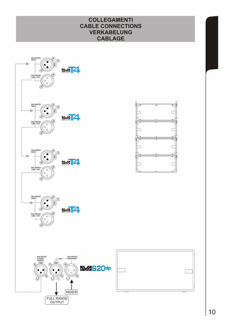
COLLEGAMENTICABLE CONNECTIONS
VERKABELUNGCABLAGE
SCHEMA A BLOCCHIBLOCK DIAGRAM
BLOCKSCHALTBILDDIAGRAMA EM BLOQURES
BALANCEDMAIN INPUTLINK
BALANCEDX-OVER OUTPUT
1 2
3
1 = GND2 = HOT3 = COLD
12
3
1 2
3
PUSHPUSH
BALANCEDINPUT
BALANCEDLINK / OUT
1 = GND2 = HOT3 = COLD
PUSH
Digital Vertical ArrayT4
MIXER
FULL RANGEOUTPUT
BALANCEDINPUT
BALANCEDLINK / OUT
1 = GND2 = HOT3 = COLD
PUSH
Digital Vertical ArrayT4
BALANCEDINPUT
BALANCEDLINK / OUT
1 = GND2 = HOT3 = COLD
PUSH
Digital Vertical ArrayT4BALANCEDINPUT
BALANCEDLINK / OUT
1 = GND2 = HOT3 = COLD
PUSH
Digital Vertical ArrayT4
22SS 00
BA
AC
EL
ND
MA
N N
PT
II
U
LN
KI
BA
AN
CD
LE
X-
VR
O
EU
PU
TO
T
0H
z9 2
0z
1H
SU
BX
VE
-OR
sitc
wh
Dg
tal
ea
ii
Dl
y
Op
ion
lt
aW
OF
R 1
”O
E8
LM
ITE
RI
SB
UP
HS
EA
swi c
ht
hse
P
a1
0°
8
Ph
se
a
0°
SG
NA
IL
-20
Bd
CO
TR
OL
CU
ITN
CIR
S
L N
IN I
PU
MA
SN
TIN
M
AS
FS
EU
NP
TI
US
NS
E
EA
YR
D
Sw
cin
Mo
de
ith
gP
ow
r S
up
ply
e PF
C
Pw
er
Fc
or
o
at
C
orr
cio
et
n
PS
SM
Ca
sD
ls
®D
IGIP
RO
lss
DC
a
WO
OE
18
FR
”
Sw
itch
ig
Md
n
oe
Pw
er
Sp
lyo
u
p
PF
C
Po
we
Fa
cto
r
rC
rre
ctio
noSM
PS
Cl
ss
Da
®G
R
DI
IPO
Ca
s
ls
D
9 10
COLLEGAMENTICABLE CONNECTIONS
VERKABELUNGCABLAGE
SCHEMA A BLOCCHIBLOCK DIAGRAM
BLOCKSCHALTBILDDIAGRAMA EM BLOQURES
BALANCEDMAIN INPUTLINK
BALANCEDX-OVER OUTPUT
1 2
3
1 = GND2 = HOT3 = COLD
12
3
1 2
3
PUSHPUSH
BALANCEDINPUT
BALANCEDLINK / OUT
1 = GND2 = HOT3 = COLD
PUSH
Digital Vertical ArrayT4
MIXER
FULL RANGEOUTPUT
BALANCEDINPUT
BALANCEDLINK / OUT
1 = GND2 = HOT3 = COLD
PUSH
Digital Vertical ArrayT4
BALANCEDINPUT
BALANCEDLINK / OUT
1 = GND2 = HOT3 = COLD
PUSH
Digital Vertical ArrayT4BALANCEDINPUT
BALANCEDLINK / OUT
1 = GND2 = HOT3 = COLD
PUSH
Digital Vertical ArrayT4
22SS 00
BA
AC
EL
ND
MA
N N
PT
II
U
LN
KI
BA
AN
CD
LE
X-
VR
O
EU
PU
TO
T
0H
z9 2
0z
1H
SU
BX
VE
-OR
sitc
wh
Dg
tal
ea
ii
Dl
y
Op
ion
lt
aW
OF
R 1
”O
E8
LM
ITE
RI
SB
UP
HS
EA
swi c
ht
hse
P
a1
0°
8
Ph
se
a
0°
SG
NA
IL
-20
Bd
CO
TR
OL
CU
ITN
CIR
S
L N
IN I
PU
MA
SN
TIN
M
AS
FS
EU
NP
TI
US
NS
E
EA
YR
D
Sw
cin
Mo
de
ith
gP
ow
r S
up
ply
e PF
C
Pw
er
Fc
or
o
at
C
orr
cio
et
n
PS
SM
Ca
sD
ls
®D
IGIP
RO
lss
DC
a
WO
OE
18
FR
”
Sw
itch
ig
Md
n
oe
Pw
er
Sp
lyo
u
p
PF
C
Po
we
Fa
cto
r
rC
rre
ctio
noSM
PS
Cl
ss
Da
®G
R
DI
IPO
Ca
s
ls
D

11 12
Utilizzo in appoggio verticale (DVA T4 montaggio “Ground stacking”)Supported use (DVA T4 ““Ground stacking” assembling)
Anwendung mit Aufst DVA T4 ““Ground stacking” DVA T4 ““Ground stacking” installation)
ützung ( Zusammenbauen) Utilisation en appui (
INSTALLAZIONEINSTALLATION
INSTALLATIONENINSTALLATIONS
Utilizzo in appoggioSupported use
Anwendung mit Aufstützung Utilisation en appui
ImpilatoStacked
AufgesetztEmpilée

13 14
Per supporto astaStand adaptor
Opzione DSA 4DSA 4 Option
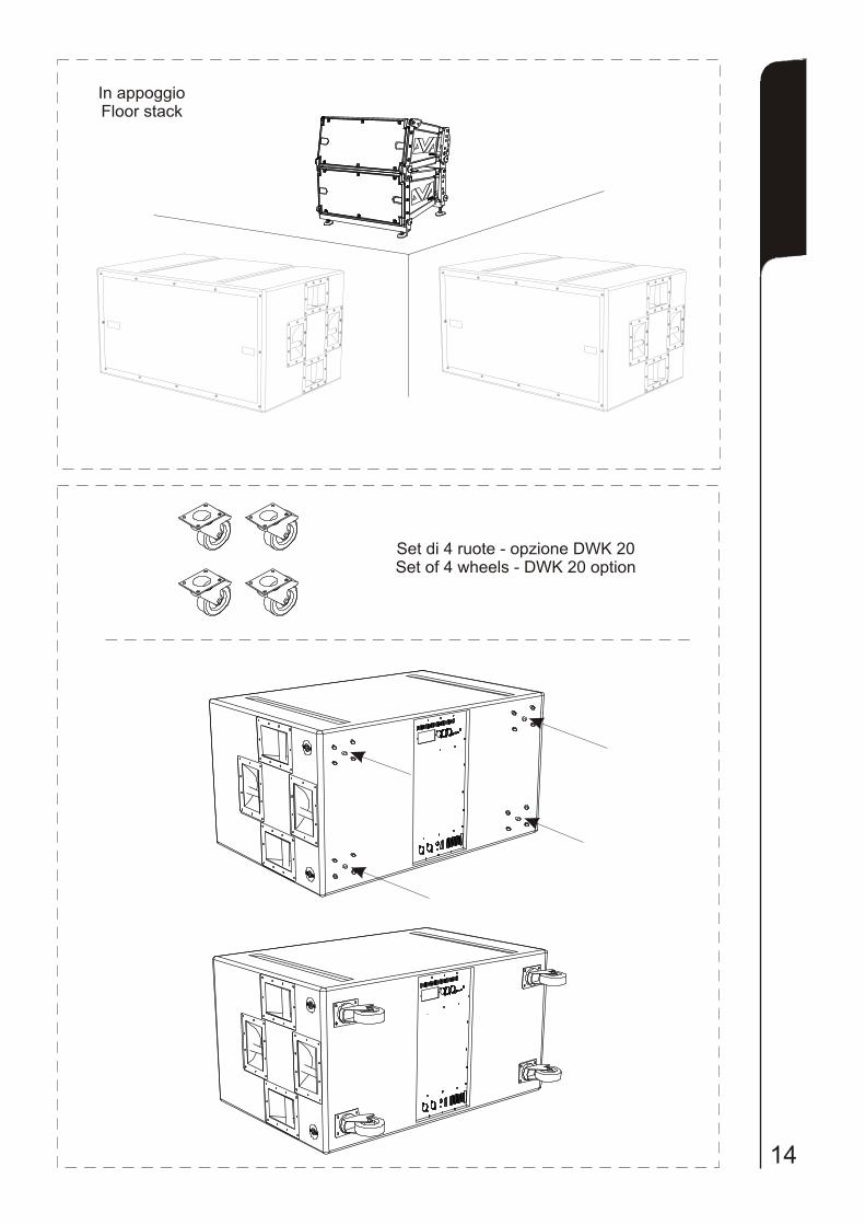
In appoggioFloor stack
Per supporto astaStand adaptor
In appoggioFloor stack
Set di 4 ruote - opzione DWK 20 Set of 4 wheels - DWK 20 option
13 14
Per supporto astaStand adaptor
Opzione DSA 4DSA 4 Option
In appoggioFloor stack
Per supporto astaStand adaptor
In appoggioFloor stack
Set di 4 ruote - opzione DWK 20 Set of 4 wheels - DWK 20 option
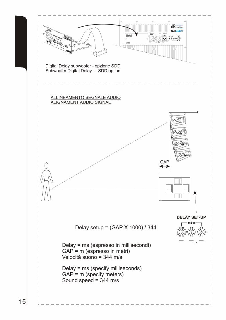
15
Digital Delay subwoofer - opzione SDDSubwoofer Digital Delay - SDD option
GAP
mSec
DELAY SET-UP
.0 .5.4
.3.1
.2
.6.7.8
.90 5
43
12
678
9
0 50
4030
1020
607080
90
- - -.
ALLINEAMENTO SEGNALE AUDIOALIGNAMENT AUDIO SIGNAL
CONFIGURAZIONE CARDIOIDECARDIOID CONFIGURATION
16
Delay setup = (GAP X 1000) / 344
PUSH
Delay = ms (specify milliseconds)GAP = m (specify meters)Sound speed = 344 m/s
Ruotare la fase di 180°Rotate 180° phase
SUBPHASE
0°
180°
Impostare il delay a 4,5msecSet delay to 4,5msec
mSec
DELAY SET-UP
.0 .5.4
.3.1
.2
.6.7.8
.90 5
43
12
678
9
0 50
4030
1020
607080
90
- - -.Delay = ms (espresso in millisecondi)GAP = m (espresso in metri)Velocità suono = 344 m/s
SUBWOOFER DIGITAL DELAYSUBWOOFER DIGITAL DELAY
DD
BBdd TECHNOLOGIESTECHNOLOGIES
SSOPTIONAL CARDOPTIONAL CARD
DDBALANCEDX-OVER OUTPUT
BALANCEDX-OVER OUTPUT
11 22
33
BBdd TECHNOLOGIESTECHNOLOGIES
22SS 00BALANCEDMAIN INPUTBALANCEDMAIN INPUTLINKLINK
+10+10
+4+4
SUB-WOOFERLEVEL
SUB-WOOFERLEVEL90Hz90Hz
120Hz120Hz 0°0°
180°180°
ONON SGNSGN LIMLIMSUBPHASE
SUBPHASE
SUBXOVER
SUBXOVER
11 22
33
1 = GND2 = HOT3 = COLD
1 = GND2 = HOT3 = COLD
1122
33
88 0dB0dB
PUSHPUSH
BALANCEDX-OVER OUTPUT
BALANCEDX-OVER OUTPUT
11 22
33
BBdd TECHNOLOGIESTECHNOLOGIES
22SS 00BALANCEDMAIN INPUTBALANCEDMAIN INPUTLINKLINK
+10+10
+4+4
SUB-WOOFERLEVEL
SUB-WOOFERLEVEL90Hz90Hz
120Hz120Hz 0°0°
180°180°
ONON SGNSGN LIMLIMSUBPHASE
SUBPHASE
SUBXOVER
SUBXOVER
11 22
33
1 = GND2 = HOT3 = COLD
1 = GND2 = HOT3 = COLD
1122
33
88 0dB0dB
PUSHPUSH
Contattare dB Technologies per gli accessori da utilizzare a corredo.Si declina ogni responsabilità da un utilizzo inappropriato degli accessori o di dispositivi aggiuntivi non idonei allo scopo.
Contact dB Technologies for accessories to be used with speakers.Will not accept any responsibilty when inappropriate accessories or not suitable additional devices are used.
Kontaktieren sie dBTechnologies für passendes Lautsprecherzubehör.Falls unpassendes Zubehör verwendet wird, wird jegliche Haftung ausgeschlossen.
Contact dBTechnologies pour les accessoires à utiliser avec la machine.N'accepterons pas toutes les responsabilités lorsque des accessoires inappropriés ou ne conviennent pas à des dispositifs supplémentaires sont utilisés.
ISTRUZIONI DI SICUREZZA PER ACCESSORI / ZUBEHÖR NSTRUCTIONS DE SÉCURITÉ
SAFETY INSTRUCTIONS FOR ACCESSORIESSICHERHEITSHINWEISE / I POUR LES ACCESSOIRES

A.E.B. INDUSTRIALE s.r.l.Via Brodolini, 8 - 40056 Crespellano (Bo) - ITALIATel. + 39 051 969870 - Fax. + 39 051 969725Internet: www.dbtechnologies.comE-mail: [email protected]
Made in Italy COD. 420120169 Rev 4.0
digital power
RR
ACTIVE SUBWOOFER
22SS 00
MANUALE d’USO - Sezione 1USER MANUAL - Section 1BEDIENUNGSANLEITUNG - Abschnitt 1CARACTERISTIQUES TECHNIQUES - Section 1