Embed Size (px)
Citation preview
1
A BRIEF INTRODUCTION INTO ORTHOPAEDIC IMPLANTS:
SCREWS, PLATES, AND NAILS
GHOLAMREZA ROUHI12
, MOHSEN AMANI1
1 Assistant Professor, Faculty of Biomedical Engineering, Amirkabir University of Technology, Tehran, Iran.
2 Adjunct Professor, School of Human Kinetics, Faculty of Health Sciences, University of Ottawa, ON, Canada.
1 Graduate Student of Biomedical Engineering, Amirkabir University of Technology, Tehran, Iran.
Introduction:
Bone, as a hard biological tissue, consists of cells resided in the bone matrix, which is
made by an organic (primarily collagen (90%) and 10% amorphous ground substance) and a
mineral phase. The main constituents of bone mineral are calcium phosphate and calcium
carbonate. The mineral components consist mainly of hydroxyapatite crystals and amorphous
calcium phosphate. Bone acts as a reservoir for our body's calcium, also serves as a protector
for vital organs, as well as provides mechanical stability to our body, and makes locomotion
possible. This hard biological tissue has a hierarchical structure and is designed optimally.
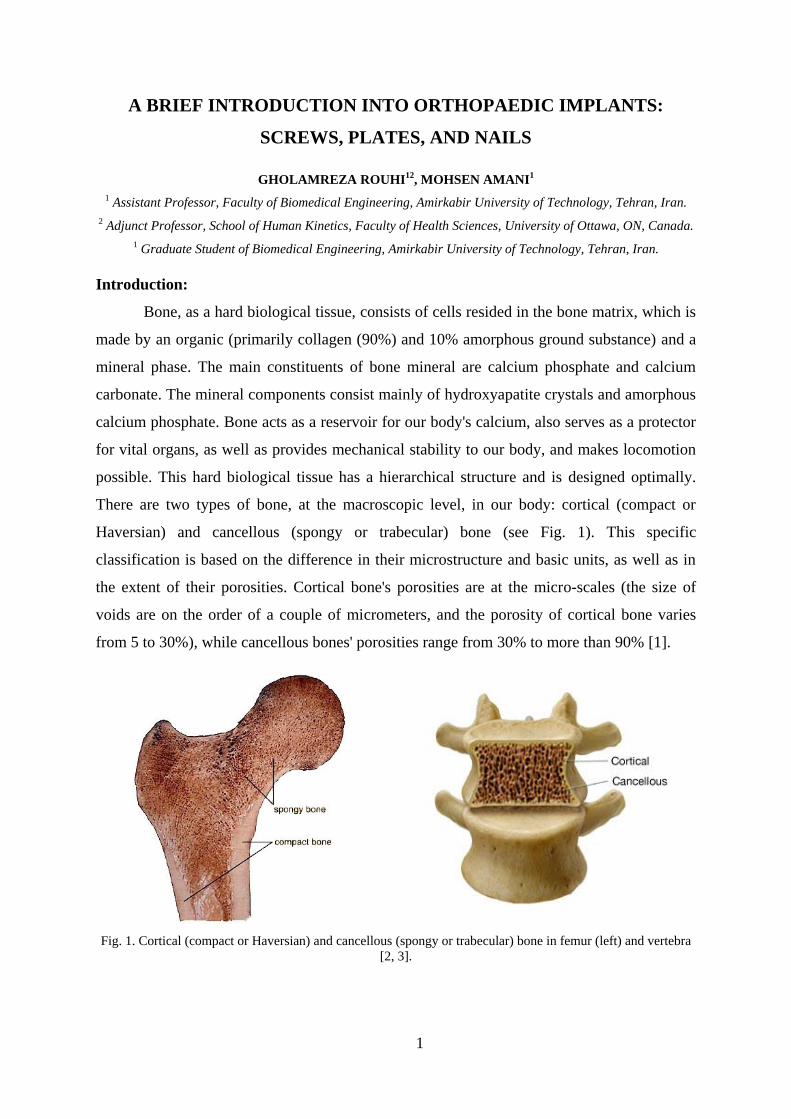
There are two types of bone, at the macroscopic level, in our body: cortical (compact or
Haversian) and cancellous (spongy or trabecular) bone (see Fig. 1). This specific
classification is based on the difference in their microstructure and basic units, as well as in
the extent of their porosities. Cortical bone's porosities are at the micro-scales (the size of
voids are on the order of a couple of micrometers, and the porosity of cortical bone varies
from 5 to 30%), while cancellous bones' porosities range from 30% to more than 90% [1].
Fig. 1. Cortical (compact or Haversian) and cancellous (spongy or trabecular) bone in femur (left) and vertebra
[2, 3].
2
Based on the arrangements of the collagen fibrils, compact and spongy bones can be
classified either as woven or parallel-fibered type. Woven bone, also called coarse-fiber bone,
is characterized by the presence in the matrix of coarse, irregularly oriented collagen fibrils.
Woven bone is the bone formed during skeletal embryogenesis, and after birth it is gradually
removed by the process of bone remodeling, and is substituted by lamellar bone. It should be
noted that the woven bone be formed in pathological conditions such as callus formation, as
well, It can be said that woven and lamellar bone are the result of a rapid and a slow
osteogenic process, respectively. On the other hand, parallel-fibered bone consists of
relatively thin and parallel-oriented collagen fibrils. Lamellar bone may be regularly
organized into unit layers called lamellae.
Bone can gain maximum strength with minimum mass due to continuous activities of
various kinds of bone cells, i.e. osteocytes, osteoblasts, osteoclasts, and bone lining cells.
There are continuous processes of bone resorption and formation in our bones from birth to
death, which is so-called, bone remodeling process [4]. Bone remodeling process aims to
provide maximum strength with minimum mass to our bones. When a bone is broken, there is
no other way than fixing it by employing man-made supportive structures. Fortunately, bone
has a great capability in re-gaining its lost strength through the healing process.
The healing process of bone is a complex process in which both medicine and
mechanics are greatly at play and they can alter the time course of the healing process.
Interesting to note that all broken bones go through the same healing process. The bone
healing process has three stages: inflammation, bone production (soft callus formation stage,
and hard callus formation stage), and bone remodeling. The inflammation stage begins the
moment the bone is broken and lasts for around five days. Fortunately bone has a very good
blood supply due to the channels within its structure. When a fracture occurs, there is massive
disruption to these blood channels and a large amount of bleeding appears from the fracture
fragments. This is what causes immediate swelling and bruising in the area of the broken
bone. This is known as a Hematoma, which means bleeding within the tissue. The damaged
bone tissue at the edges of the fracture fragments die back and the dead cells release
chemicals called cytokines, which initiate the healing process. Within hours of the fracture,
the blood from the fracture fragments forms a mesh of clotted blood, which is the first link
between the two fragments and contains special cells called fibroblasts. Fibroblasts begin to
lay down tissue called granulation tissue between 4 and 10 days after the fracture occurs. The
granulation tissue forms a scaffold between the two fragments from which the formation of a
3
soft callus can begin. Fibroblast cells present in the granulation tissue begin to form cartilage
and fibrocartilage. This is a spongy material that fills the gap between the two fracture
fragments, although it is quite weak to external mechanical stimuli for around six weeks. For
this reason it is important that there is not too much movement of the fracture fragments at
this stage. After a couple of weeks, despite the very fragile nature of soft callus, it offers
sufficient stability at the fracture site for new blood vessels to begin forming and for
osteoblasts at the periosteum (the outer surface of the bone) to begin laying down what is
called woven bone. This woven bone at the margins of the fracture is a little soft and
disorganized, but it makes the first bone contact between the two fracture fragments.
From two to three weeks onwards a process begins whereby the fragile cartilage
material of the soft callus is transformed completely into woven bone. This process typically
continues for between six and twelve weeks, depending on the location and type of fracture
(generally six weeks for the upper limb and twelve weeks for the lower limb). Hard Callus
formation is a complex process that is guided by the release of mineral compounds such as
Calcium and Phosphate into the Cartilage tissue, which subsequently transforms into a bridge
of Hard Callus over the fracture site. Once the hard callus has formed at the fracture site, then
fracture union is said to have occurred. Fracture union can be seen on x-ray at around six
weeks in upper limb fractures and twelve weeks in lower limb fractures. During normal bone
healing the body will lay down harder callus than is needed, and as a result the fracture site
enlarges. Bone remodeling begins once the fracture has united and may continue for several
years. Through the remodeling process and over time, the normal shape of the bone is
regained. Bone is resorbed where is not needed by osteoclasts and formed by osteoblasts
where is needed. At the bone remodeling stage of fracture healing, a progression of weight
bearing exercise is encouraged because it leads to an increase in bone strength. During the
course of the bone remodeling process, the loosely organized woven bone is gradually
replaced by lamellar bone, which is highly organized and much stronger than woven bone.
Orthopedic implants can be defined as medical devices used to replace or provide
fixation of bone, or to replace articulating surfaces of a joint. In simpler words, orthopedic
implants are used to either assist or replace damaged or troubled bones and joints. Orthopedic
implants are mainly made from stainless steel and titanium alloys for strength and lined with
plastic to act as artificial cartilage in order to reduce the stress at the articulating surfaces.
Some implants are cemented into place and others are pressed to fit, so that your bone can
grow into the implant for strength. Some examples of orthopaedic implants are: orthopaedic
4
plates, orthopaedic nails, and orthopaedic screws. The key factor that guides bone healing is
the interfragmentary movement, which determines the tissue strain and consequently the
cellular reaction in the fracture healing zone. Thus, the methods of fracture fixation will be
evaluated by considering their ability to reduce the interfragmentary movement. To achieve
good and acceptable healing results, biomechanical principles should be understood and
carefully taken into consideration.
Orthopedic Screws:
The helical-thread screw is surely an extremely important invention in Mechanical
Engineering, which changes angular motion to linear motion to transmit power, or to develop
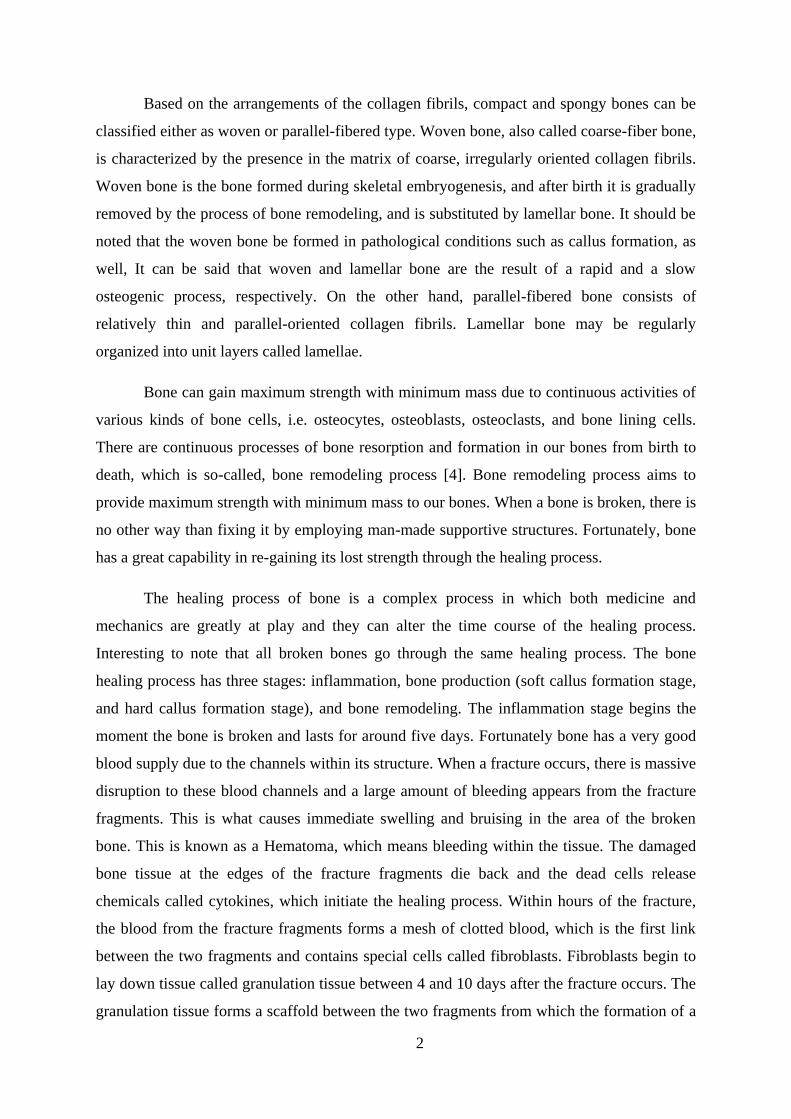
large forces. Screws are complex tools with a four-part construction: head, shaft, thread, and
tip. The head serves as an attachment for the screw driver, which may be hexagonal, cruciate,
slotted, or Philips in design. The head also serves as the counterforce against which
compression generated by the screw acts on the bone. The shaft or shank is the smooth
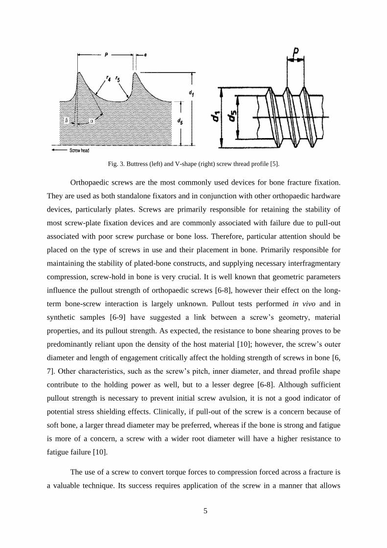
portion of the screw between the head and the threaded region. The thread is defined by its
root (or core) diameter, its thread (or outside) diameter, its pitch (or distance between
adjacent threads), and its lead (or distance it advances into the bone with each complete turn)
(see Fig. 2). The root area determines the resistance of the screw to pull-out forces and relates
to the area of the bone at the thread interface and the root area of the tapped thread. The
cross-sectional design is usually a buttress or V-thread (usually used in machine screws) (see
Fig. 3). The tip of the screw is either round (requires pretapping) or self-tapping (fluted or
trocar).
Fig. 2. Screw terms definition [5].
5
Fig. 3. Buttress (left) and V-shape (right) screw thread profile [5].
Orthopaedic screws are the most commonly used devices for bone fracture fixation.
They are used as both standalone fixators and in conjunction with other orthopaedic hardware
devices, particularly plates. Screws are primarily responsible for retaining the stability of
most screw-plate fixation devices and are commonly associated with failure due to pull-out
associated with poor screw purchase or bone loss. Therefore, particular attention should be
placed on the type of screws in use and their placement in bone. Primarily responsible for
maintaining the stability of plated-bone constructs, and supplying necessary interfragmentary
compression, screw-hold in bone is very crucial. It is well known that geometric parameters
influence the pullout strength of orthopaedic screws [6-8], however their effect on the long-
term bone-screw interaction is largely unknown. Pullout tests performed in vivo and in
synthetic samples [6-9] have suggested a link between a screw’s geometry, material
properties, and its pullout strength. As expected, the resistance to bone shearing proves to be
predominantly reliant upon the density of the host material [10]; however, the screw’s outer
diameter and length of engagement critically affect the holding strength of screws in bone [6,
7]. Other characteristics, such as the screw’s pitch, inner diameter, and thread profile shape
contribute to the holding power as well, but to a lesser degree [6-8]. Although sufficient
pullout strength is necessary to prevent initial screw avulsion, it is not a good indicator of
potential stress shielding effects. Clinically, if pull-out of the screw is a concern because of
soft bone, a larger thread diameter may be preferred, whereas if the bone is strong and fatigue
is more of a concern, a screw with a wider root diameter will have a higher resistance to
fatigue failure [10].
The use of a screw to convert torque forces to compression forced across a fracture is
a valuable technique. Its success requires application of the screw in a manner that allows
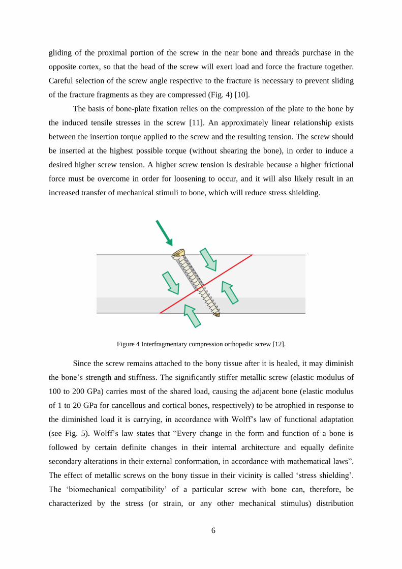
6
gliding of the proximal portion of the screw in the near bone and threads purchase in the
opposite cortex, so that the head of the screw will exert load and force the fracture together.
Careful selection of the screw angle respective to the fracture is necessary to prevent sliding
of the fracture fragments as they are compressed (Fig. 4) [10].
The basis of bone-plate fixation relies on the compression of the plate to the bone by
the induced tensile stresses in the screw [11]. An approximately linear relationship exists
between the insertion torque applied to the screw and the resulting tension. The screw should
be inserted at the highest possible torque (without shearing the bone), in order to induce a
desired higher screw tension. A higher screw tension is desirable because a higher frictional
force must be overcome in order for loosening to occur, and it will also likely result in an
increased transfer of mechanical stimuli to bone, which will reduce stress shielding.
Figure 4 Interfragmentary compression orthopedic screw [12].
Since the screw remains attached to the bony tissue after it is healed, it may diminish
the bone’s strength and stiffness. The significantly stiffer metallic screw (elastic modulus of
100 to 200 GPa) carries most of the shared load, causing the adjacent bone (elastic modulus
of 1 to 20 GPa for cancellous and cortical bones, respectively) to be atrophied in response to
the diminished load it is carrying, in accordance with Wolff’s law of functional adaptation
(see Fig. 5). Wolff’s law states that “Every change in the form and function of a bone is
followed by certain definite changes in their internal architecture and equally definite
secondary alterations in their external conformation, in accordance with mathematical laws”.
The effect of metallic screws on the bony tissue in their vicinity is called ‘stress shielding’.
The ‘biomechanical compatibility’ of a particular screw with bone can, therefore, be
characterized by the stress (or strain, or any other mechanical stimulus) distribution
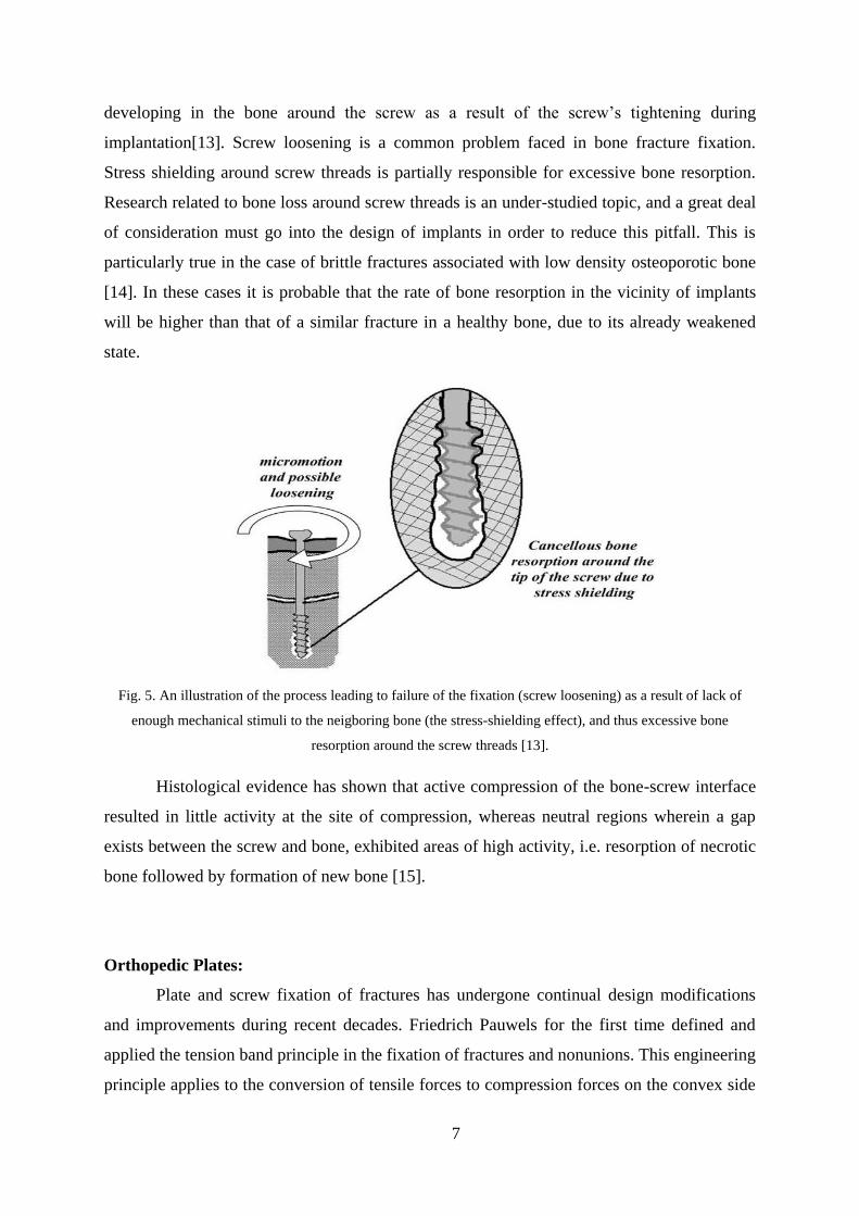
7
developing in the bone around the screw as a result of the screw’s tightening during
implantation[13]. Screw loosening is a common problem faced in bone fracture fixation.
Stress shielding around screw threads is partially responsible for excessive bone resorption.
Research related to bone loss around screw threads is an under-studied topic, and a great deal
of consideration must go into the design of implants in order to reduce this pitfall. This is
particularly true in the case of brittle fractures associated with low density osteoporotic bone
[14]. In these cases it is probable that the rate of bone resorption in the vicinity of implants
will be higher than that of a similar fracture in a healthy bone, due to its already weakened
state.
Fig. 5. An illustration of the process leading to failure of the fixation (screw loosening) as a result of lack of
enough mechanical stimuli to the neigboring bone (the stress-shielding effect), and thus excessive bone
resorption around the screw threads [13].
Histological evidence has shown that active compression of the bone-screw interface
resulted in little activity at the site of compression, whereas neutral regions wherein a gap
exists between the screw and bone, exhibited areas of high activity, i.e. resorption of necrotic
bone followed by formation of new bone [15].
Orthopedic Plates:
Plate and screw fixation of fractures has undergone continual design modifications
and improvements during recent decades. Friedrich Pauwels for the first time defined and
applied the tension band principle in the fixation of fractures and nonunions. This engineering
principle applies to the conversion of tensile forces to compression forces on the convex side
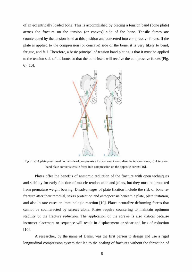
8
of an eccentrically loaded bone. This is accomplished by placing a tension band (bone plate)
across the fracture on the tension (or convex) side of the bone. Tensile forces are
counteracted by the tension band at this position and converted into compressive forces. If the
plate is applied to the compression (or concave) side of the bone, it is very likely to bend,
fatigue, and fail. Therefore, a basic principal of tension band plating is that it must be applied
to the tension side of the bone, so that the bone itself will receive the compressive forces (Fig.
6) [10].
Fig. 6. a) A plate positioned on the side of compressive forces cannot neutralize the tension force, b) A tension
band plate converts tensile force into compression on the opposite cortex [16].
Plates offer the benefits of anatomic reduction of the fracture with open techniques
and stability for early function of muscle-tendon units and joints, but they must be protected
from premature weight bearing. Disadvantages of plate fixation include the risk of bone re-
fracture after their removal, stress protection and osteoporosis beneath a plate, plate irritation,
and also in rare cases an immunologic reaction [10]. Plates neutralize deforming forces that
cannot be counteracted by screws alone. Plates require countering to maintain optimum
stability of the fracture reduction. The application of the screws is also critical because
incorrect placement or sequence will result in displacement or shear and loss of reduction
[10].
A researcher, by the name of Danis, was the first person to design and use a rigid
longitudinal compression system that led to the healing of fractures without the formation of
9
a visible callus [17]. This type of conventional rigid plating promotes primary healing
through the direct compression of the plate to bone with or without a removable compressor
and is now known as the AO/ASIF method (Association for the study of internal fixation).
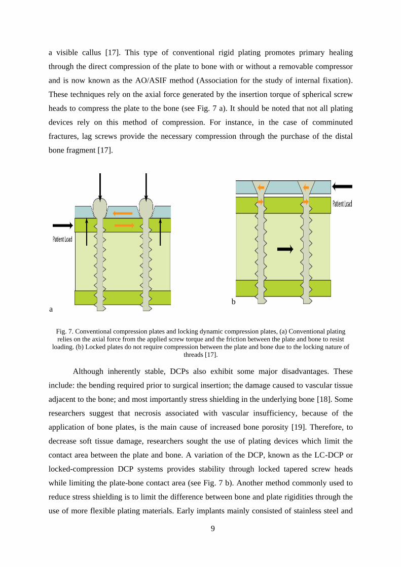
These techniques rely on the axial force generated by the insertion torque of spherical screw
heads to compress the plate to the bone (see Fig. 7 a). It should be noted that not all plating
devices rely on this method of compression. For instance, in the case of comminuted
fractures, lag screws provide the necessary compression through the purchase of the distal
bone fragment [17].
a b
Fig. 7. Conventional compression plates and locking dynamic compression plates, (a) Conventional plating
relies on the axial force from the applied screw torque and the friction between the plate and bone to resist
loading. (b) Locked plates do not require compression between the plate and bone due to the locking nature of
threads [17].
Although inherently stable, DCPs also exhibit some major disadvantages. These
include: the bending required prior to surgical insertion; the damage caused to vascular tissue
adjacent to the bone; and most importantly stress shielding in the underlying bone [18]. Some
researchers suggest that necrosis associated with vascular insufficiency, because of the
application of bone plates, is the main cause of increased bone porosity [19]. Therefore, to
decrease soft tissue damage, researchers sought the use of plating devices which limit the
contact area between the plate and bone. A variation of the DCP, known as the LC-DCP or
locked-compression DCP systems provides stability through locked tapered screw heads
while limiting the plate-bone contact area (see Fig. 7 b). Another method commonly used to
reduce stress shielding is to limit the difference between bone and plate rigidities through the
use of more flexible plating materials. Early implants mainly consisted of stainless steel and
10
vitallium alloys [20]. Interesting to note that there is still much controversy between the use
of completely rigid systems and systems with increased material flexibility [21]. Some
researchers believe that a small amount of micro-motion at the fracture site promotes more
rapid fracture healing, because a combination of primary and secondary healing can occur in
this case [22]. As it is a well-accepted concept, flexural rigidity is dependent both on the
cross-sectional area and material properties of the plating device [23]. In terms of materials,
less rigid titanium alloy devices with increased resistance to corrosion have proven to be
advantageous [17], and are slowly beginning to replace stainless steel devices that previously
dominated the market. Experimental evidence reveals an increasing trend towards the general
acceptance of more flexible systems, as the level of stress shielding is reduced [24-26].
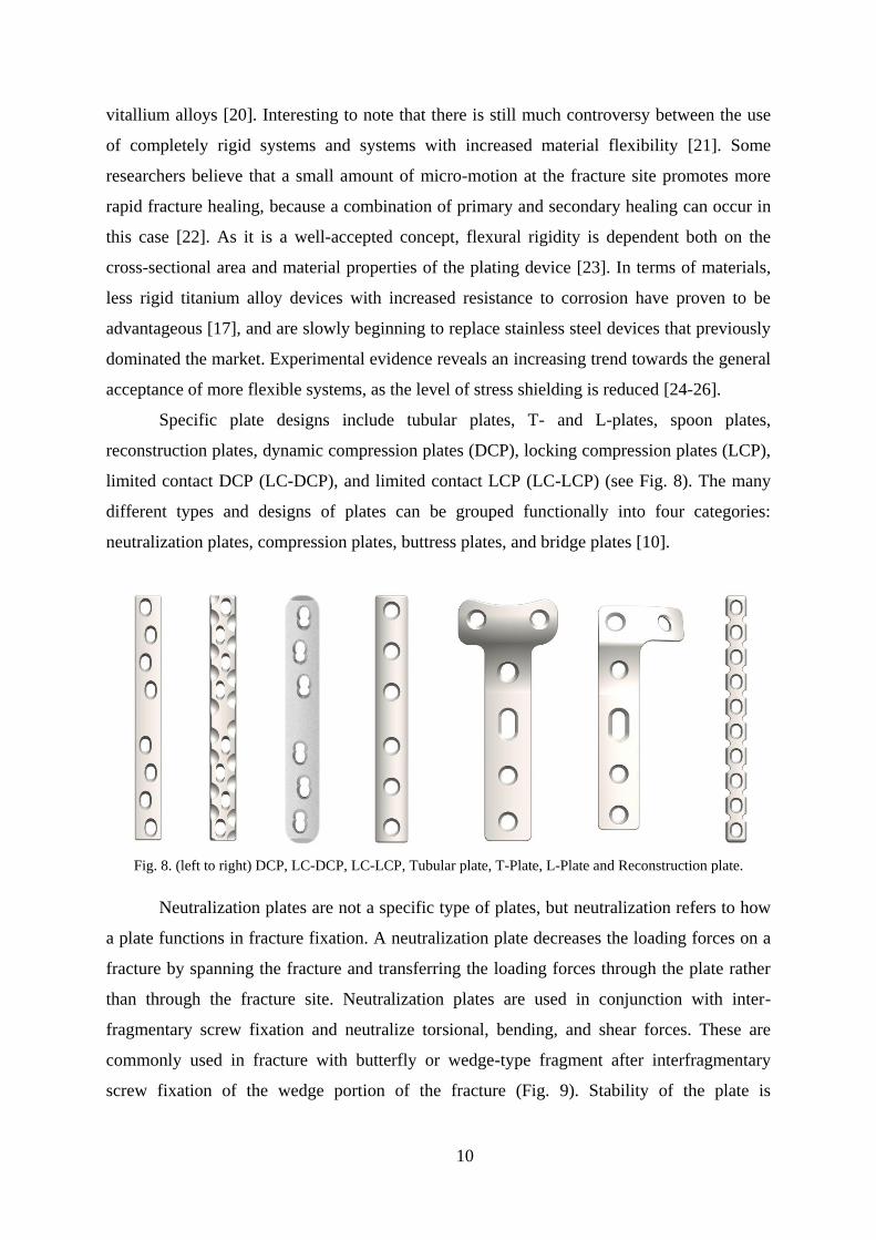
Specific plate designs include tubular plates, T- and L-plates, spoon plates,
reconstruction plates, dynamic compression plates (DCP), locking compression plates (LCP),
limited contact DCP (LC-DCP), and limited contact LCP (LC-LCP) (see Fig. 8). The many
different types and designs of plates can be grouped functionally into four categories:
neutralization plates, compression plates, buttress plates, and bridge plates [10].
Fig. 8. (left to right) DCP, LC-DCP, LC-LCP, Tubular plate, T-Plate, L-Plate and Reconstruction plate.
Neutralization plates are not a specific type of plates, but neutralization refers to how
a plate functions in fracture fixation. A neutralization plate decreases the loading forces on a
fracture by spanning the fracture and transferring the loading forces through the plate rather
than through the fracture site. Neutralization plates are used in conjunction with inter-
fragmentary screw fixation and neutralize torsional, bending, and shear forces. These are
commonly used in fracture with butterfly or wedge-type fragment after interfragmentary
screw fixation of the wedge portion of the fracture (Fig. 9). Stability of the plate is
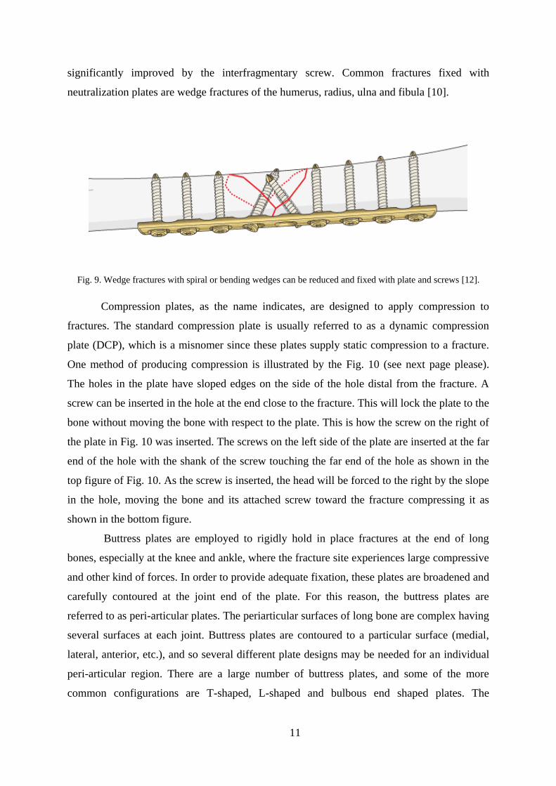
11
significantly improved by the interfragmentary screw. Common fractures fixed with
neutralization plates are wedge fractures of the humerus, radius, ulna and fibula [10].
Fig. 9. Wedge fractures with spiral or bending wedges can be reduced and fixed with plate and screws [12].
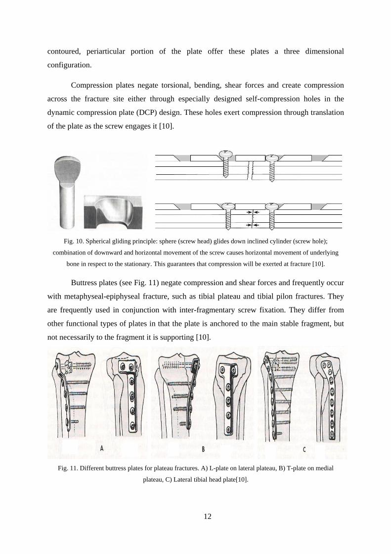
Compression plates, as the name indicates, are designed to apply compression to
fractures. The standard compression plate is usually referred to as a dynamic compression
plate (DCP), which is a misnomer since these plates supply static compression to a fracture.
One method of producing compression is illustrated by the Fig. 10 (see next page please).
The holes in the plate have sloped edges on the side of the hole distal from the fracture. A
screw can be inserted in the hole at the end close to the fracture. This will lock the plate to the
bone without moving the bone with respect to the plate. This is how the screw on the right of
the plate in Fig. 10 was inserted. The screws on the left side of the plate are inserted at the far
end of the hole with the shank of the screw touching the far end of the hole as shown in the
top figure of Fig. 10. As the screw is inserted, the head will be forced to the right by the slope
in the hole, moving the bone and its attached screw toward the fracture compressing it as
shown in the bottom figure.
Buttress plates are employed to rigidly hold in place fractures at the end of long
bones, especially at the knee and ankle, where the fracture site experiences large compressive
and other kind of forces. In order to provide adequate fixation, these plates are broadened and
carefully contoured at the joint end of the plate. For this reason, the buttress plates are
referred to as peri-articular plates. The periarticular surfaces of long bone are complex having
several surfaces at each joint. Buttress plates are contoured to a particular surface (medial,
lateral, anterior, etc.), and so several different plate designs may be needed for an individual
peri-articular region. There are a large number of buttress plates, and some of the more
common configurations are T-shaped, L-shaped and bulbous end shaped plates. The
12
contoured, periarticular portion of the plate offer these plates a three dimensional
configuration.
Compression plates negate torsional, bending, shear forces and create compression
across the fracture site either through especially designed self-compression holes in the
dynamic compression plate (DCP) design. These holes exert compression through translation
of the plate as the screw engages it [10].
Fig. 10. Spherical gliding principle: sphere (screw head) glides down inclined cylinder (screw hole);
combination of downward and horizontal movement of the screw causes horizontal movement of underlying
bone in respect to the stationary. This guarantees that compression will be exerted at fracture [10].
Buttress plates (see Fig. 11) negate compression and shear forces and frequently occur
with metaphyseal-epiphyseal fracture, such as tibial plateau and tibial pilon fractures. They
are frequently used in conjunction with inter-fragmentary screw fixation. They differ from
other functional types of plates in that the plate is anchored to the main stable fragment, but
not necessarily to the fragment it is supporting [10].
Fig. 11. Different buttress plates for plateau fractures. A) L-plate on lateral plateau, B) T-plate on medial
plateau, C) Lateral tibial head plate[10].
13
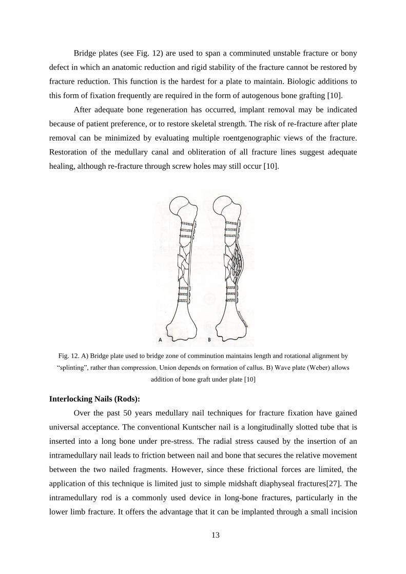
Bridge plates (see Fig. 12) are used to span a comminuted unstable fracture or bony
defect in which an anatomic reduction and rigid stability of the fracture cannot be restored by
fracture reduction. This function is the hardest for a plate to maintain. Biologic additions to
this form of fixation frequently are required in the form of autogenous bone grafting [10].
After adequate bone regeneration has occurred, implant removal may be indicated
because of patient preference, or to restore skeletal strength. The risk of re-fracture after plate
removal can be minimized by evaluating multiple roentgenographic views of the fracture.
Restoration of the medullary canal and obliteration of all fracture lines suggest adequate
healing, although re-fracture through screw holes may still occur [10].
Fig. 12. A) Bridge plate used to bridge zone of comminution maintains length and rotational alignment by
“splinting”, rather than compression. Union depends on formation of callus. B) Wave plate (Weber) allows
addition of bone graft under plate [10]
Interlocking Nails (Rods):
Over the past 50 years medullary nail techniques for fracture fixation have gained
universal acceptance. The conventional Kuntscher nail is a longitudinally slotted tube that is
inserted into a long bone under pre-stress. The radial stress caused by the insertion of an
intramedullary nail leads to friction between nail and bone that secures the relative movement
between the two nailed fragments. However, since these frictional forces are limited, the
application of this technique is limited just to simple midshaft diaphyseal fractures[27]. The
intramedullary rod is a commonly used device in long-bone fractures, particularly in the
lower limb fracture. It offers the advantage that it can be implanted through a small incision
14
and without considerable surgical exposure. Closed interlocking nail fixation is the procedure
of choice for femoral shaft fractures, especially in poly-trauma patients. This treatment
modality has been the subject of controversy since its introduction because of concerns of
damage to the medullary circulation, possibilities of embolism, and complications from
misapplications of the technique because of a lack of understanding of the biomechanical
principles of medullary nail fixation [10].
Various types of medullary nails are centromedullary nails, condylocephalic nails,
cephalomedullary nails, centromedullary interlocking nails, and cephalomedullary
interlocking nails. Centromedullary nails enter the bone in line with the medullary canal.
They obtain contact with the bone through multiple points of longitudinal interference. They
depend on restoration of bony contact and stability to avoid axial and rotational deformation
of the fracture. Condylocephalic nails enter the bone in the condyles of the metaphyseal-
epiphyseal area. They frequently are inserted in groups for added rotational stability.
Cephalomedullary nails have a centromedullary portion, but also permit fixation up into the
femoral head [10].
A perfect medullary nail has not yet been designed. The varying contour of bones
make invention of such a nail actually impossible, but improvement in the design of
medullary nails should seriously continue. A medullary nail should meet the following
requirements[10]:
1. It should be strong enough and provide sufficient stability to maintain alignment and
position, including prevention of rotation; it should include interlocking transfixing
screws as necessary;
2. It should be constructed so that contact-compression forces may impact the fracture
surfaces, a desirable physiologic stimulus to union; and
3. It should be placed so that it is accessible for easy removal; attachments are provided
to facilitate removal.
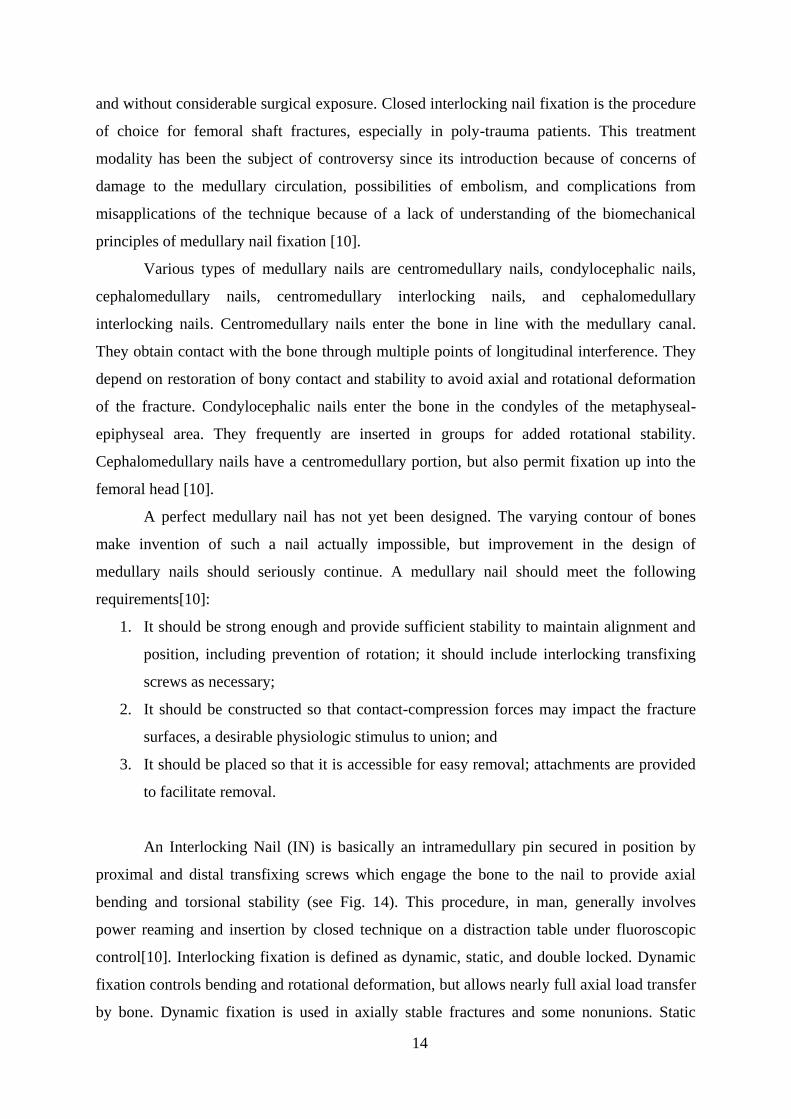
An Interlocking Nail (IN) is basically an intramedullary pin secured in position by
proximal and distal transfixing screws which engage the bone to the nail to provide axial
bending and torsional stability (see Fig. 14). This procedure, in man, generally involves
power reaming and insertion by closed technique on a distraction table under fluoroscopic
control[10]. Interlocking fixation is defined as dynamic, static, and double locked. Dynamic
fixation controls bending and rotational deformation, but allows nearly full axial load transfer
by bone. Dynamic fixation is used in axially stable fractures and some nonunions. Static
15
fixation controls rotation, bending, and axial load and makes the implant a more load-bearing
device with the potential for a reduced fatigue life. It is especially useful in comminuted,
nonisthmal fractures of the femur and tibia. The double-locked mode controls bending,
rotational forces, and some axial deformation, but because of capability of axial translation of
the screw within the nail, some shortening is possible. This mode of fixation is used in
fracture of the humerus and occasionally in delayed unions and nonunions [10].
a b
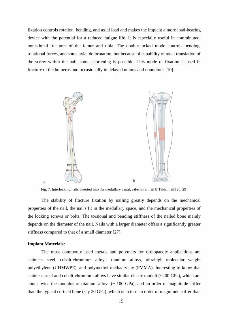
Fig. 7. Interlocking nails inserted into the medullary canal, a)Femoral nail b)Tibial nail.[28, 29]
The stability of fracture fixation by nailing greatly depends on the mechanical
properties of the nail, the nail's fit in the medullary space, and the mechanical properties of
the locking screws or bolts. The torsional and bending stiffness of the nailed bone mainly
depends on the diameter of the nail. Nails with a larger diameter offers a significantly greater
stiffness compared to that of a small diameter [27].
Implant Materials:
The most commonly used metals and polymers for orthopaedic applications are
stainless steel, cobalt-chromium alloys, titanium alloys, ultrahigh molecular weight
polyethylene (UHMWPE), and polymethyl methacrylate (PMMA). Interesting to know that
stainless steel and cobalt-chromium alloys have similar elastic moduli (~200 GPa), which are
about twice the modulus of titanium alloys (~ 100 GPa), and an order of magnitude stiffer
than the typical cortical bone (say 20 GPa), which is in turn an order of magnitude stiffer than
16
either UHMWPE or PMMA. In addition, cobalt-chromium and titanium alloys are typically
less ductile and stronger than stainless steels. The properties of medical grade stainless steel
provide a balance between high strength, ductility, and fatigue performance. Ductility is
essential for fracture fixation components, since they should be deformed in the operating
room to conform to the bone curvature at the fracture site. Corrosion resistance is another
important consideration, which is achieved in stainless steels by keeping the carbide content
to a minimum and by including chromium. Resistance to pitting and crevice corrosion is also
very important and can increase with increasing chromium, molybdenum, and nitrogen.
When components are manufactured by stainless steel, cobalt, chromium nickel oxide layer is
formed by passivation of the devices in a strong nitric acid bath. If the protective layer is
scratched, no serious problem arises since the film can reform. This oxide layer increases the
in vivo corrosion resistance by offering a passive layer between the tissues and bulk material.
The titanium based material most commonly used in orthopaedic applications is titanium-
aluminum-vanadium alloy, Ti-6Al-4V. Unalloyed pure titanium can be used for implants
where high stresses are not expected, e.g. fracture fixation devices for wrists and hands. But,
if high strength is needed, titanium alloys must be employed. An adherent layer of titanium
oxide (TiO2) provides corrosion resistance that greatly exceeds that of stainless steel and the
cobalt alloys, even in saline solutions. It also has excellent resistance to pitting, intergranulkar
and crevice corrosion. Moreover, the oxide layer of titanium and its alloys offer excellent
interfaces with bone, which can grow right up to the implant surface without considerable
fibrous tissue formation that can be seen in other metal-bone interfaces. Another advantage of
titanium implants is their biocompatibility from the stress shielding point of view (because of
their lower modulus of elasticity compared to that of stainless steel and cobalt-chromium
alloys). It should be noted that Ti6Al4V alloy is a notch-sensitive materials, and without
additional surface treatment, it shows very poor wear resistance compared to stainless steel
and cobalt-chromium alloys [30].
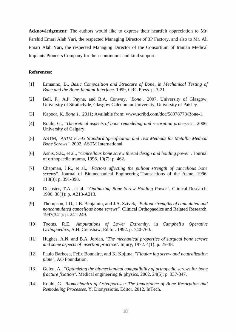
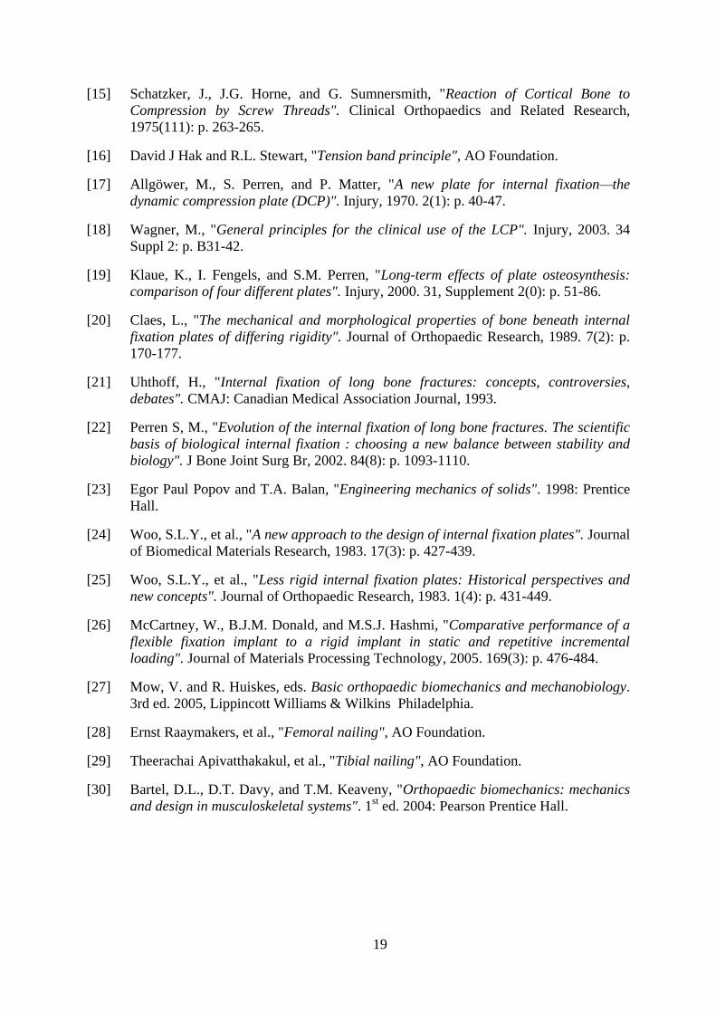
Sample Products of Pooyandegan Pezeshki Pardis (3P):
The following figures are pictures from some of 3P Factory products including screws
(Fig. 15), plates (Fig. 16), and nails (Fig. 17).
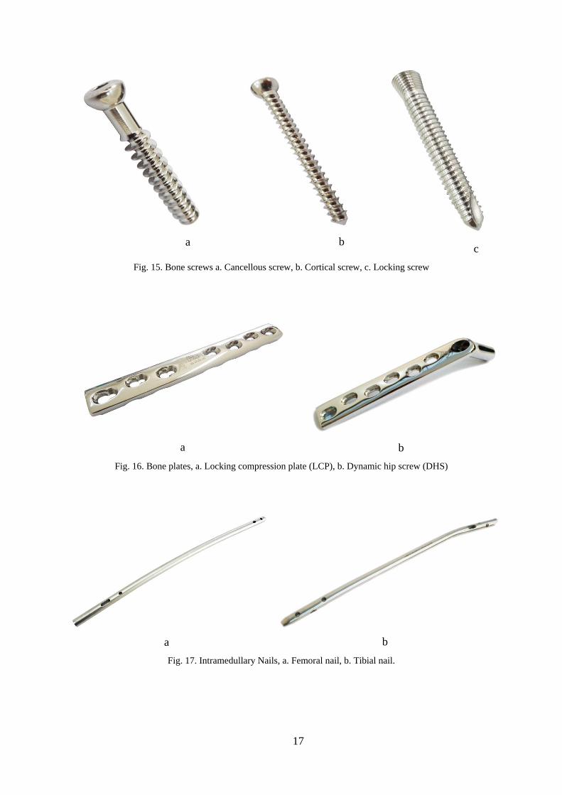
17
a
b
c
Fig. 15. Bone screws a. Cancellous screw, b. Cortical screw, c. Locking screw
a b
Fig. 16. Bone plates, a. Locking compression plate (LCP), b. Dynamic hip screw (DHS)
a b
Fig. 17. Intramedullary Nails, a. Femoral nail, b. Tibial nail.
18
Acknowledgement: The authors would like to express their heartfelt appreciation to Mr.
Farshid Emari Alah Yari, the respected Managing Director of 3P Factory, and also to Mr. Ali
Emari Alah Yari, the respected Managing Director of the Consortium of Iranian Medical
Implants Pioneers Company for their continuous and kind support.
References:
[1] Ermanno, B., Basic Composition and Structure of Bone, in Mechanical Testing of
Bone and the Bone-Implant Interface. 1999, CRC Press. p. 3-21.
[2] Bell, F., A.P. Payne, and B.A. Conway, "Bone". 2007, University of Glasgow,
University of Strathclyde, Glasgow Caledonian University, University of Paisley.
[3] Kapoor, K. Bone 1. 2011; Available from: www.scribd.com/doc/58978778/Bone-1.
[4] Rouhi, G., "Theoretical aspects of bone remodeling and resorption processes". 2006,
University of Calgary.
[5] ASTM, "ASTM F 543 Standard Specification and Test Methods for Metallic Medical
Bone Screws". 2002, ASTM International.
[6] Asnis, S.E., et al., "Cancellous bone screw thread design and holding power". Journal
of orthopaedic trauma, 1996. 10(7): p. 462.
[7] Chapman, J.R., et al., "Factors affecting the pullout strength of cancellous bone
screws". Journal of Biomechanical Engineering-Transactions of the Asme, 1996.
118(3): p. 391-398.
[8] Decoster, T.A., et al., "Optimizing Bone Screw Holding Power". Clinical Research,
1990. 38(1): p. A213-A213.
[9] Thompson, J.D., J.B. Benjamin, and J.A. Szivek, "Pullout strengths of cannulated and
noncannulated cancellous bone screws". Clinical Orthopaedics and Related Research,
1997(341): p. 241-249.
[10] Tooms, R.E., Amputations of Lower Extremity, in Campbell's Operative
Orthopaedics, A.H. Crenshaw, Editor. 1992. p. 740-760.
[11] Hughes, A.N. and B.A. Jordan, "The mechanical properties of surgical bone screws
and some aspects of insertion practice". Injury, 1972. 4(1): p. 25-38.
[12] Paulo Barbosa, Felix Bonnaire, and K. Kojima, "Fibular lag screw and neutralization
plate", AO Foundation.
[13] Gefen, A., "Optimizing the biomechanical compatibility of orthopedic screws for bone
fracture fixation". Medical engineering & physics, 2002. 24(5): p. 337-347.
[14] Rouhi, G., Biomechanics of Osteoporosis: The Importance of Bone Resorption and
Remodeling Processes, Y. Dionyssiotis, Editor. 2012, InTech.
19
[15] Schatzker, J., J.G. Horne, and G. Sumnersmith, "Reaction of Cortical Bone to
Compression by Screw Threads". Clinical Orthopaedics and Related Research,
1975(111): p. 263-265.
[16] David J Hak and R.L. Stewart, "Tension band principle", AO Foundation.
[17] Allgöwer, M., S. Perren, and P. Matter, "A new plate for internal fixation—the
dynamic compression plate (DCP)". Injury, 1970. 2(1): p. 40-47.
[18] Wagner, M., "General principles for the clinical use of the LCP". Injury, 2003. 34
Suppl 2: p. B31-42.
[19] Klaue, K., I. Fengels, and S.M. Perren, "Long-term effects of plate osteosynthesis:
comparison of four different plates". Injury, 2000. 31, Supplement 2(0): p. 51-86.
[20] Claes, L., "The mechanical and morphological properties of bone beneath internal
fixation plates of differing rigidity". Journal of Orthopaedic Research, 1989. 7(2): p.
170-177.
[21] Uhthoff, H., "Internal fixation of long bone fractures: concepts, controversies,
debates". CMAJ: Canadian Medical Association Journal, 1993.
[22] Perren S, M., "Evolution of the internal fixation of long bone fractures. The scientific
basis of biological internal fixation : choosing a new balance between stability and
biology". J Bone Joint Surg Br, 2002. 84(8): p. 1093-1110.
[23] Egor Paul Popov and T.A. Balan, "Engineering mechanics of solids". 1998: Prentice
Hall.
[24] Woo, S.L.Y., et al., "A new approach to the design of internal fixation plates". Journal
of Biomedical Materials Research, 1983. 17(3): p. 427-439.
[25] Woo, S.L.Y., et al., "Less rigid internal fixation plates: Historical perspectives and
new concepts". Journal of Orthopaedic Research, 1983. 1(4): p. 431-449.
[26] McCartney, W., B.J.M. Donald, and M.S.J. Hashmi, "Comparative performance of a
flexible fixation implant to a rigid implant in static and repetitive incremental
loading". Journal of Materials Processing Technology, 2005. 169(3): p. 476-484.
[27] Mow, V. and R. Huiskes, eds. Basic orthopaedic biomechanics and mechanobiology.
3rd ed. 2005, Lippincott Williams & Wilkins Philadelphia.
[28] Ernst Raaymakers, et al., "Femoral nailing", AO Foundation.
[29] Theerachai Apivatthakakul, et al., "Tibial nailing", AO Foundation.
[30] Bartel, D.L., D.T. Davy, and T.M. Keaveny, "Orthopaedic biomechanics: mechanics
and design in musculoskeletal systems". 1st ed. 2004: Pearson Prentice Hall.


![IS 10235-1 (1982): Glossary of Terms, Part I: General ... · Medical Terms for Surgical Implants [MHD 2: Orthopaedic Instruments, Implants and Accessories] Indian Standard ... New](https://img.pdfslide.us/doc/110x75/5f2d659731962a1f97457cd7/is-10235-1-1982-glossary-of-terms-part-i-general-medical-terms-for-surgical.jpg)