Embed Size (px)
Citation preview
A Beginners Guide to EMC
Presented by Andy LawsonTechnical Supervisor, Industry EMC, TÜV SÜD Product Service
• EMC Issues In The Real World
• What Actually is EMC?
• EMC Standards and Legislation
• The Need For EMC
• How EMC Problems Occur
• EMC Control Measures
• Some Basics Of EMC
EMC Issues
In The Real World –
• Broadcast Interference
• Equipment Malfunction
What is EMC? The IEC definition
•EMC: Electromagnetic compatibility:
"The ability of an equipment or system to function satisfactorily in its electromagnetic environment without introducing intolerable electromagnetic disturbances to anything in that environment.“
(IEC defines the electromagnetic (EM) environment as "the totality of electromagnetic EM phenomena existing at a given location.")
The need for EMC
• limit interference to broadcast reception
and mobile radio services, and other users
of the mains supply
• immunity of safety- or user-critical systems
from environmental effects (especially
transport, medical and process control)
EMC LEGISLATION &
STANDARDS
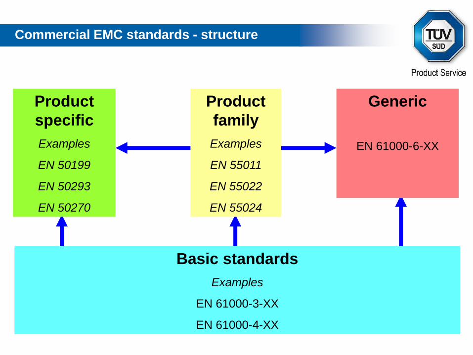
Commercial EMC standards - structure
Basic standards
Examples
EN 61000-3-XX
EN 61000-4-XX
Product
specific
Examples
EN 50199
EN 50293
EN 50270
Product
family
Examples
EN 55011
EN 55022
EN 55024
Generic
EN 61000-6-XX
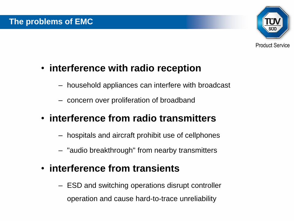
The problems of EMC
• interference with radio reception
– household appliances can interfere with broadcast
– concern over proliferation of broadband
• interference from radio transmitters
– hospitals and aircraft prohibit use of cellphones
– "audio breakthrough" from nearby transmitters
• interference from transients
– ESD and switching operations disrupt controller
operation and cause hard-to-trace unreliability
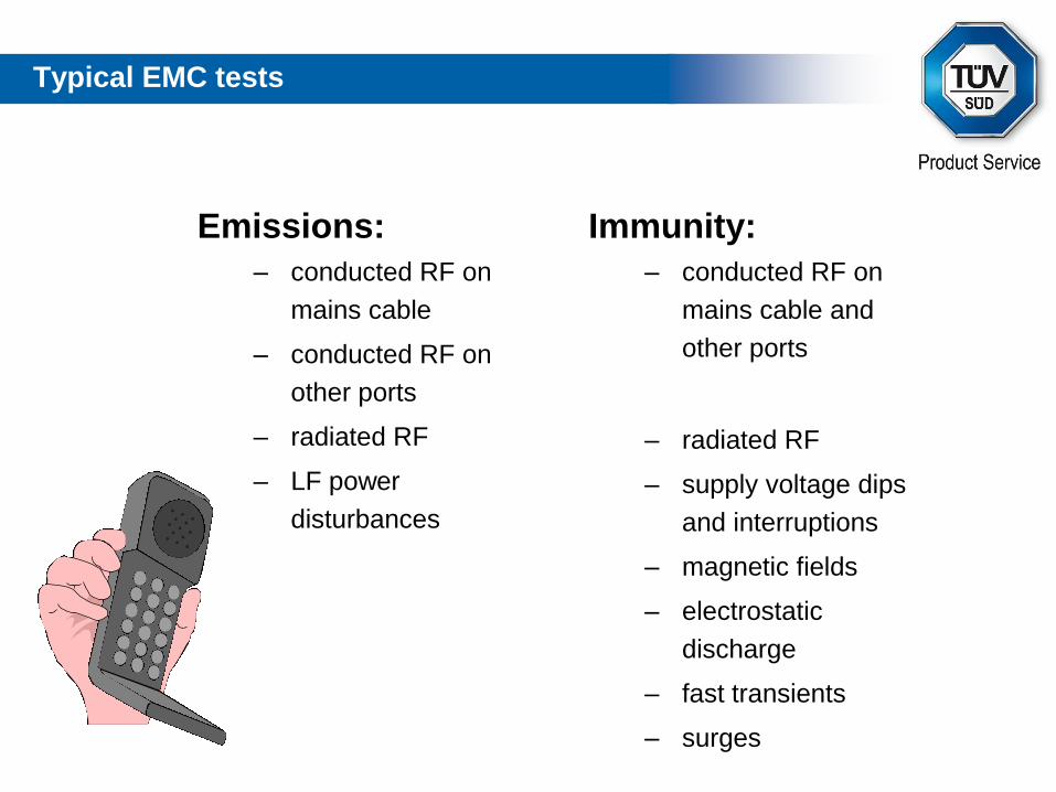
Typical EMC tests
Emissions:
– conducted RF on
mains cable
– conducted RF on
other ports
– radiated RF
– LF power
disturbances
Immunity:
– conducted RF on
mains cable and
other ports
– radiated RF
– supply voltage dips
and interruptions
– magnetic fields
– electrostatic
discharge
– fast transients
– surges
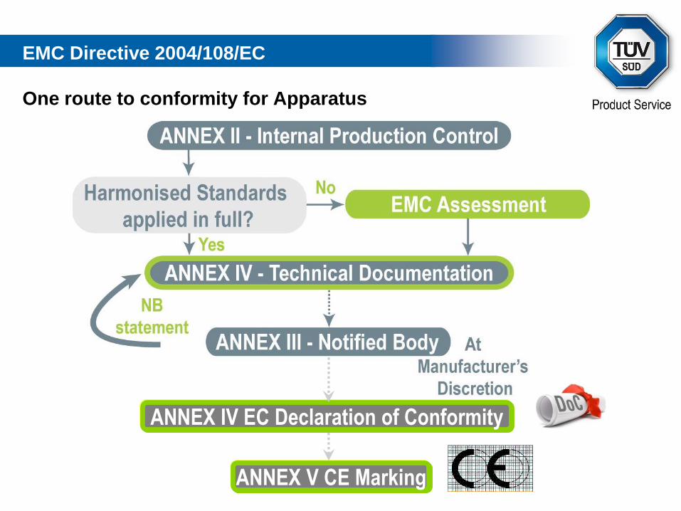
EMC Directive 2004/108/EC
One route to conformity for Apparatus
ANNEX IV EC Declaration of Conformity
ANNEX V CE Marking
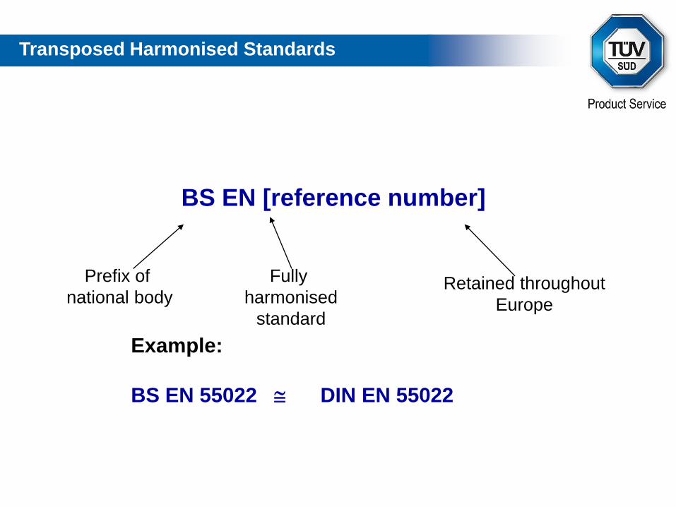
Transposed Harmonised Standards
Fully
harmonised
standard
BS EN [reference number]
Prefix of
national bodyRetained throughout
Europe
Example:
BS EN 55022 DIN EN 55022
HOW DO EMC
PROBLEMS OCCUR?
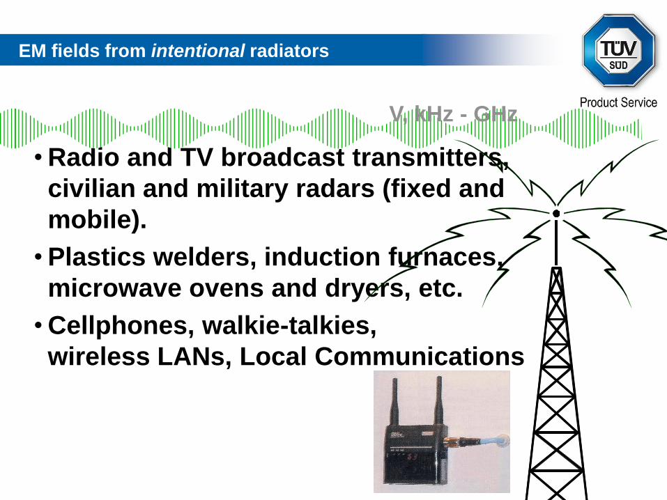
EM fields from intentional radiators
• Radio and TV broadcast transmitters,
civilian and military radars (fixed and
mobile).
• Plastics welders, induction furnaces,
microwave ovens and dryers, etc.
• Cellphones, walkie-talkies,
wireless LANs, Local Communications
V, kHz - GHz
Abcde fgh ijkl mn
opqrst uvw Abcde fgh
ijkl mn opqrst uvw
Abcde fgh ijkl mn
opqrst uvw Abcde fgh
ijkl mn opqrst uvw
Abcde fgh ijkl mn
opqrst uvw Abcde fgh
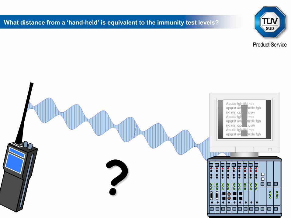
What distance from a ‘hand-held’ is equivalent to the immunity test levels?
?!
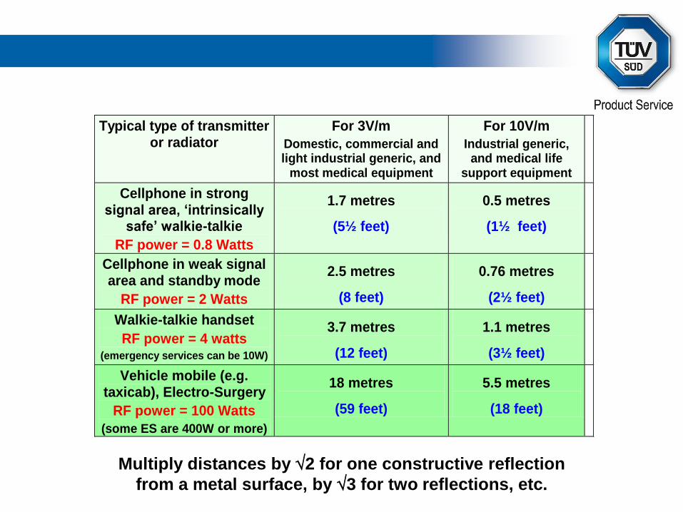
Typical type of transmitter or radiator
For 3V/m
Domestic, commercial and light industrial generic, and
most medical equipment
For 10V/m
Industrial generic, and medical life
support equipment
Cellphone in strong signal area, ‘intrinsically
safe’ walkie-talkie
RF power = 0.8 Watts
1.7 metres
(5½ feet)
0.5 metres
(1½ feet)
Cellphone in weak signal area and standby mode
RF power = 2 Watts
2.5 metres
(8 feet)
0.76 metres
(2½ feet)
Walkie-talkie handset
RF power = 4 watts (emergency services can be 10W)
3.7 metres
(12 feet)
1.1 metres
(3½ feet)
Vehicle mobile (e.g. taxicab), Electro-Surgery
RF power = 100 Watts
(some ES are 400W or more)
18 metres
(59 feet)
5.5 metres
(18 feet)
Multiply distances by 2 for one constructive reflection
from a metal surface, by 3 for two reflections, etc.
EM fields caused by unintentional radiators
• Everything which uses electricity or electronics always ‘leaks’
and so emits some EM disturbances
– the higher the rate of change of voltage or current,
the worse the emissions tend to be
• Power and signals in devices, printed circuit board (PCB)
traces, wires and cables leak EM waves
• Shielded enclosures leak EM waves from apertures, gaps and
joints
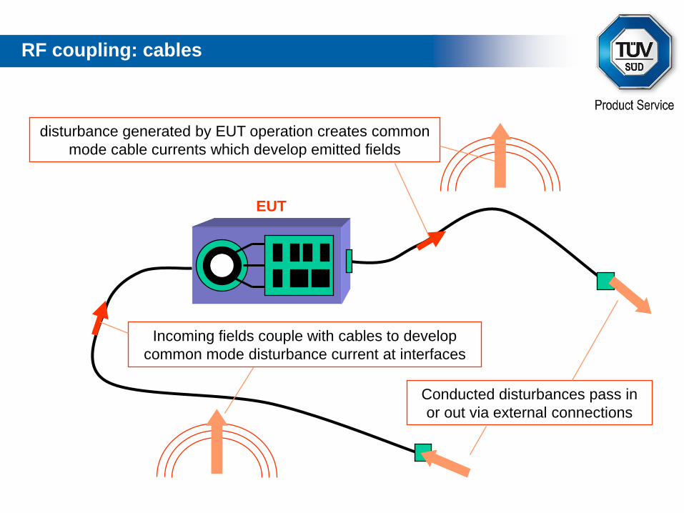
RF coupling: cables
EUT
Conducted disturbances pass in
or out via external connections
Incoming fields couple with cables to develop
common mode disturbance current at interfaces
disturbance generated by EUT operation creates common
mode cable currents which develop emitted fields
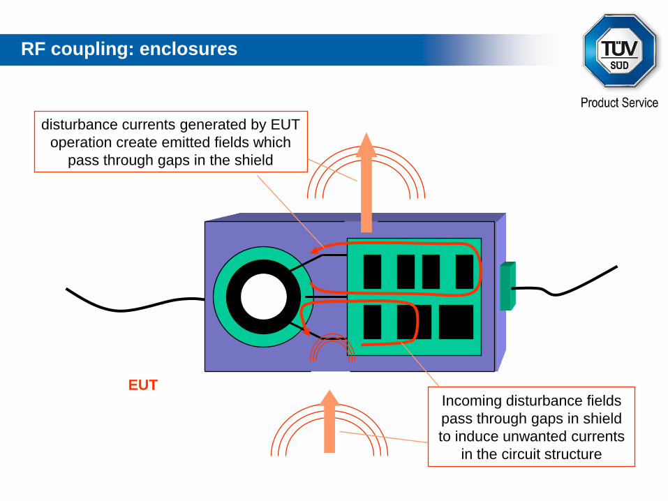
RF coupling: enclosures
EUT
disturbance currents generated by EUT
operation create emitted fields which
pass through gaps in the shield
Incoming disturbance fields
pass through gaps in shield
to induce unwanted currents
in the circuit structure
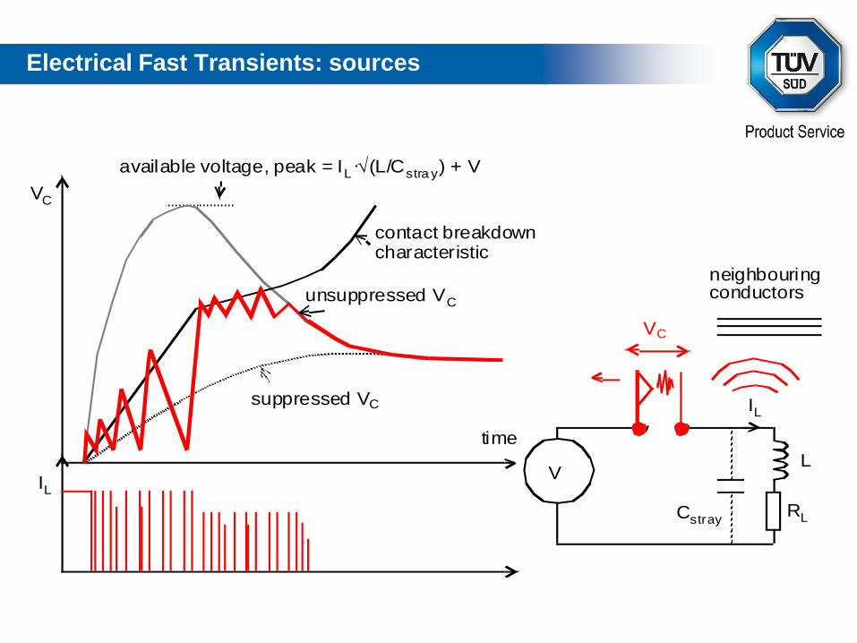
Electrical Fast Transients: sources
CstrayRL
L
IL
neighbouringconductors
V
VC
suppressed VC
unsuppressed VC
available voltage, peak = IL ∙(L/Cstra y) + V
contact breakdowncharacteristic
VC
time
IL
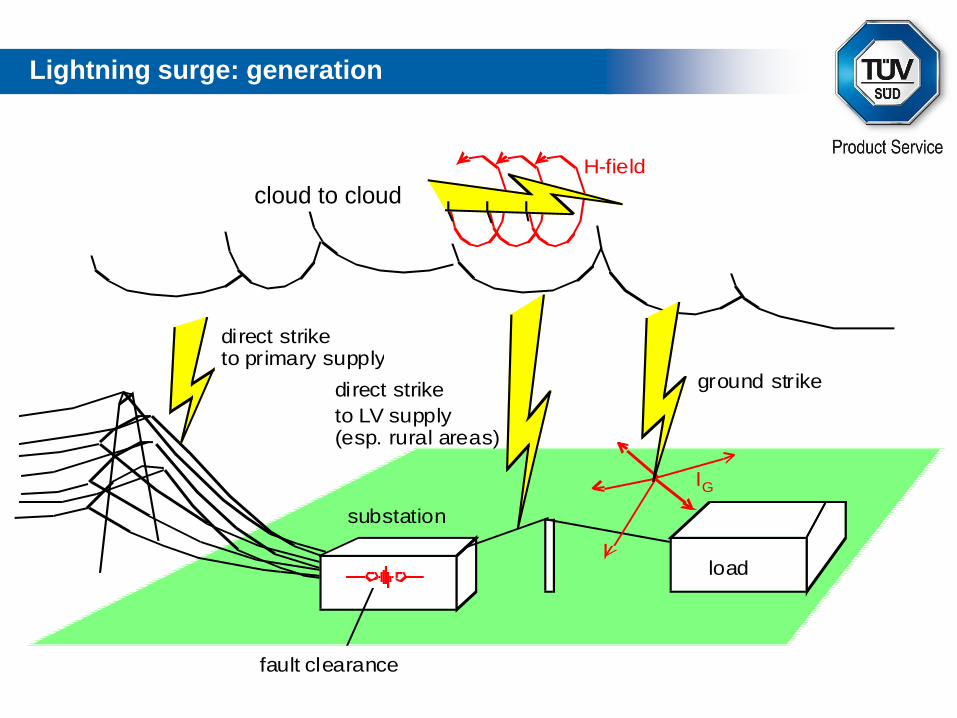
Lightning surge: generation
substation
load
direct striketo primary supply
direct strike
to LV supply(esp. rural areas)
IG
ground strike
H-field
cloud to cloud
fault clearance
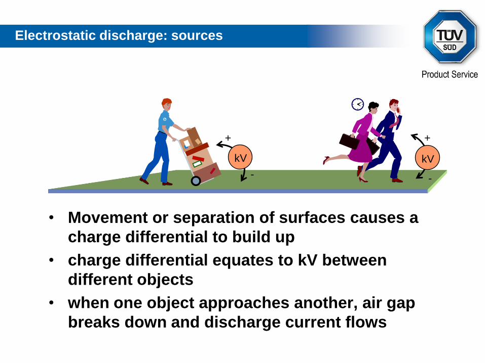
Electrostatic discharge: sources
• Movement or separation of surfaces causes a
charge differential to build up
• charge differential equates to kV between
different objects
• when one object approaches another, air gap
breaks down and discharge current flows
kV
+
-
kV
+
-
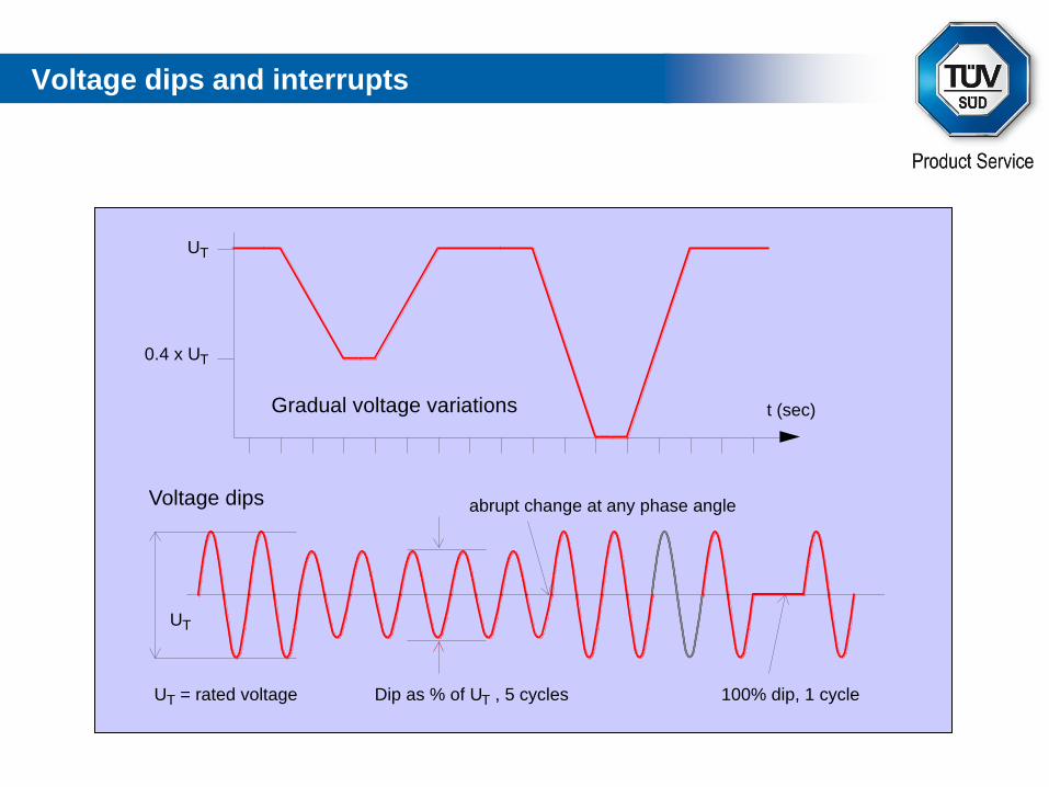
Voltage dips and interrupts
UT
UT = rated voltage Dip as % of UT , 5 cycles 100% dip, 1 cycle
abrupt change at any phase angle
t (sec)
UT
0.4 x UT
Gradual voltage variations
Voltage dips
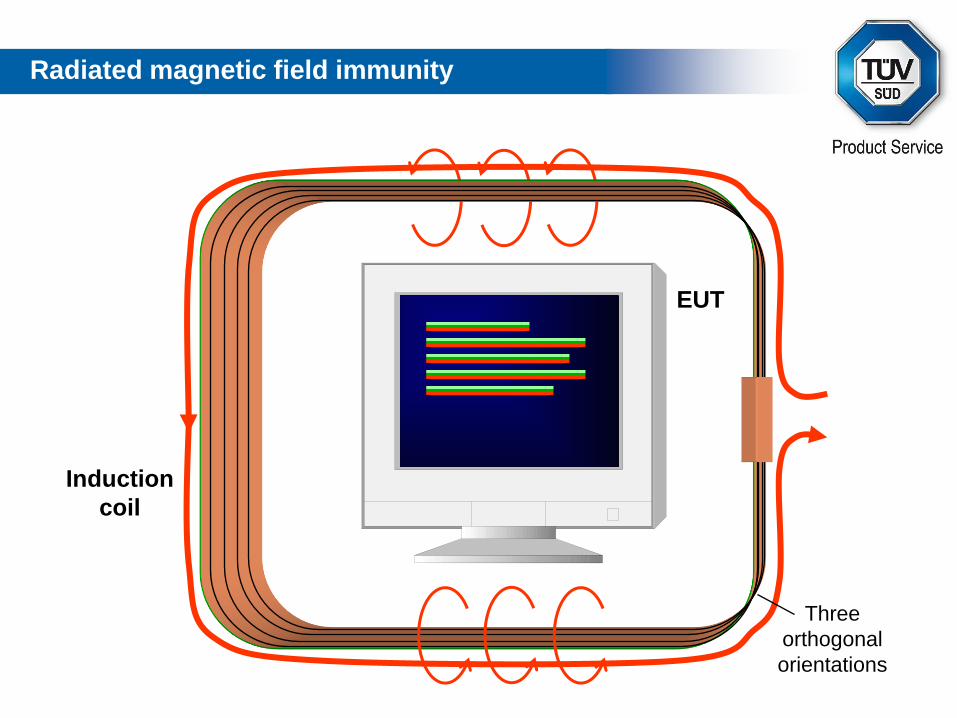
Radiated magnetic field immunity
EUT
Induction
coil
Three
orthogonal
orientations
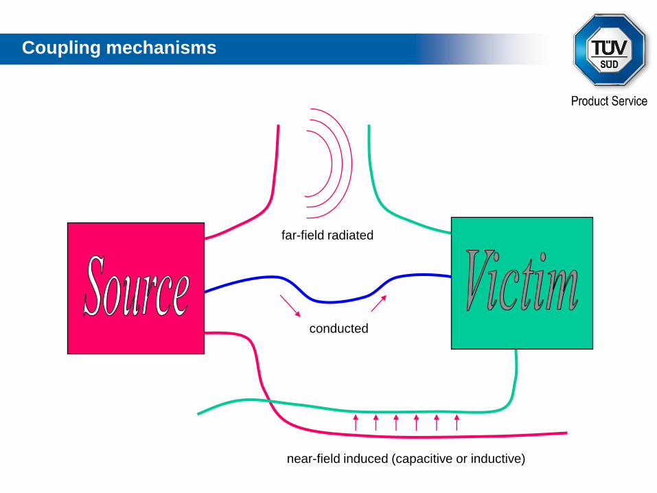
Coupling mechanisms
far-field radiated
near-field induced (capacitive or inductive)
conducted
A TYPICAL PROBLEM
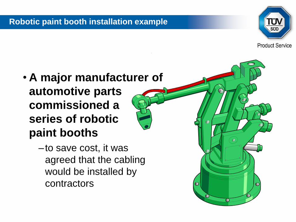
Robotic paint booth installation example
• A major manufacturer of
automotive parts
commissioned a
series of robotic
paint booths
– to save cost, it was
agreed that the cabling
would be installed by
contractors
Robotic paint booth installation continued...
• The paint booths suffered random
(and sometimes dangerous) faults
• 80% of the shielded cables had to
be replaced
– this time using correct shield termination
methods
Robotic paint booth installation continued...
• The supplier had not provided
any instructions on the correct
termination of the
screened cables
–so, after protracted legal
arguments, he picked up
the bill for the modifications
–and also had to pay the
penalty clauses in the contract
$
EMC CONTROL
MEASURES
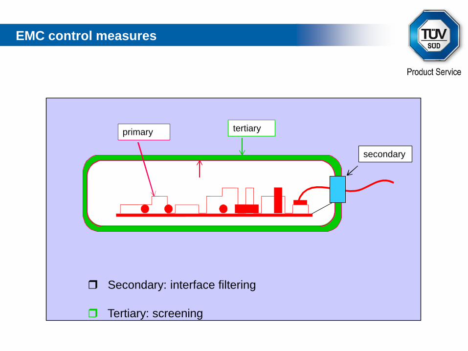
Primary: circuit design and PCB layout
tertiary
EMC control measures
primary
secondary
Secondary: interface filtering
Tertiary: screening
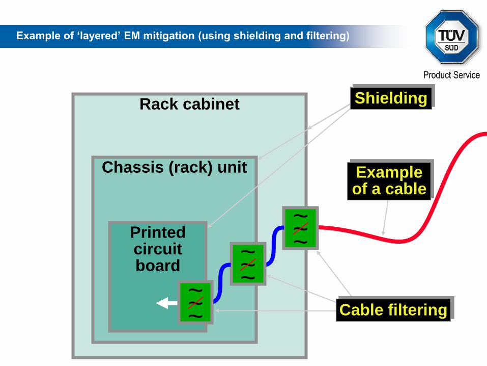
Rack cabinet
~~~
Example of ‘layered’ EM mitigation (using shielding and filtering)
Chassis (rack) unit
~~~
Shielding
Example of a cable
Cable filtering
Printed circuit board
~~~
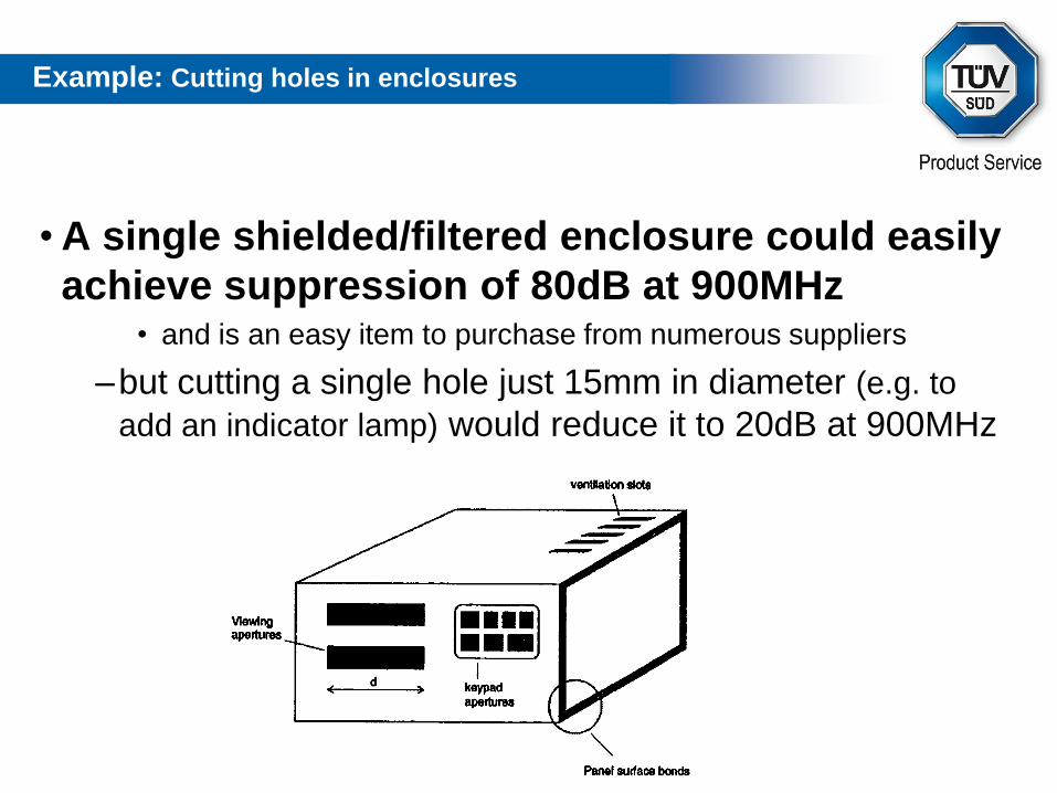
Example: Cutting holes in enclosures
• A single shielded/filtered enclosure could easily
achieve suppression of 80dB at 900MHz• and is an easy item to purchase from numerous suppliers
–but cutting a single hole just 15mm in diameter (e.g. to
add an indicator lamp) would reduce it to 20dB at 900MHz
SOME BASICS OF EMC
ESD
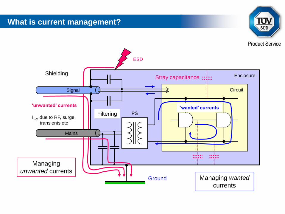
What is current management?
Mains
Signal
PS
Circuit
Enclosure
Ground
Filtering
ShieldingStray capacitance
‘wanted’ currents‘unwanted’ currents
ICM due to RF, surge,
transients etc
Managing
unwanted currentsManaging wanted
currents
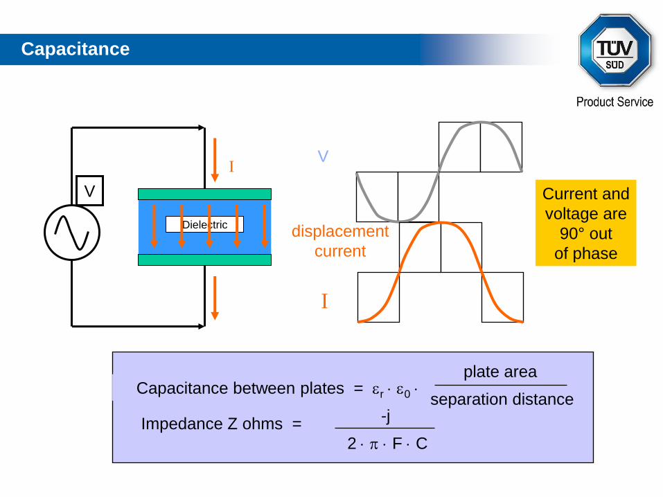
Capacitance
Dielectric
V
IV
Current and
voltage are
90° out
of phase
I
displacement
current
Capacitance between plates = er e0 plate area
separation distance
Impedance Z ohms =-j
2 p F C
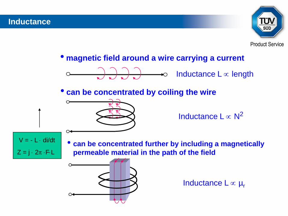
Inductance
• magnetic field around a wire carrying a current
• can be concentrated by coiling the wire
• can be concentrated further by including a magnetically
permeable material in the path of the field
Inductance L length
Inductance L N2
Inductance L µr
V = - L di/dt
Z = j 2p FL
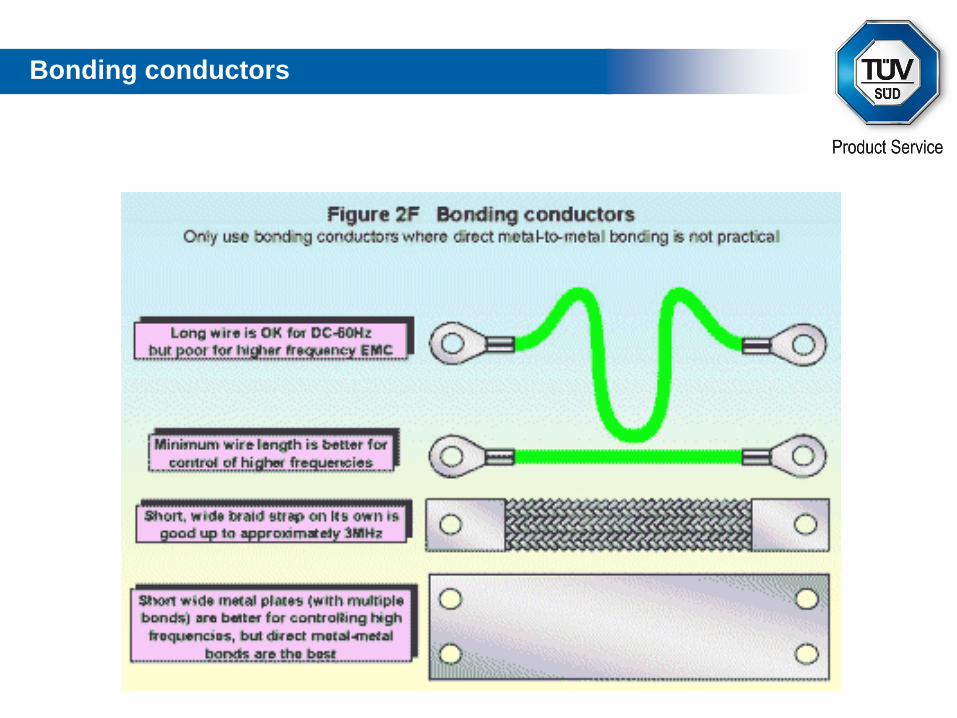
Bonding conductors
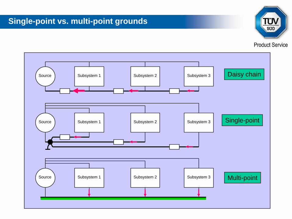
Single-point vs. multi-point grounds
Subsystem 1 Subsystem 2 Subsystem 3Source
Subsystem 1 Subsystem 2 Subsystem 3Source
Subsystem 1 Subsystem 2 Subsystem 3Source
Daisy chain
Single-point
Multi-point
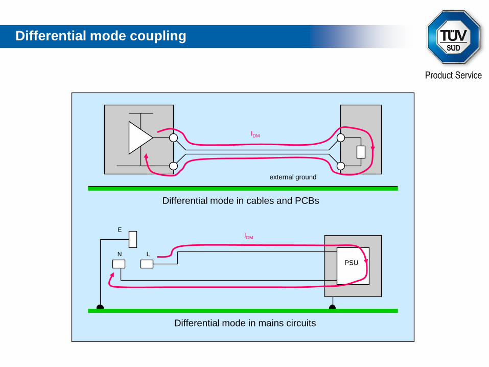
Differential mode coupling
Differential mode in mains circuits
LN
E
PSU
Differential mode in cables and PCBs
external ground
IDM
IDM
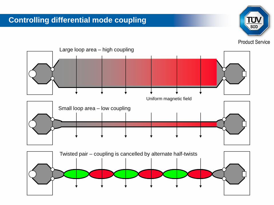
Controlling differential mode coupling
Large loop area – high coupling
Small loop area – low coupling
Twisted pair – coupling is cancelled by alternate half-twists
Uniform magnetic field
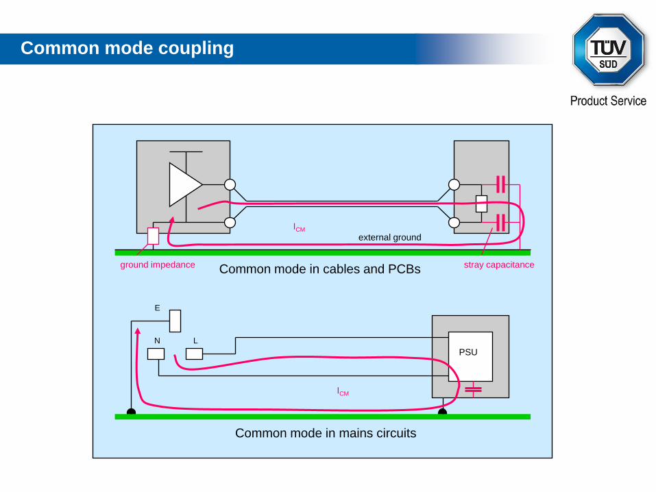
Common mode coupling
Common mode in cables and PCBs
external ground
stray capacitanceground impedance
Common mode in mains circuits
LN
E
PSU
ICM
ICM
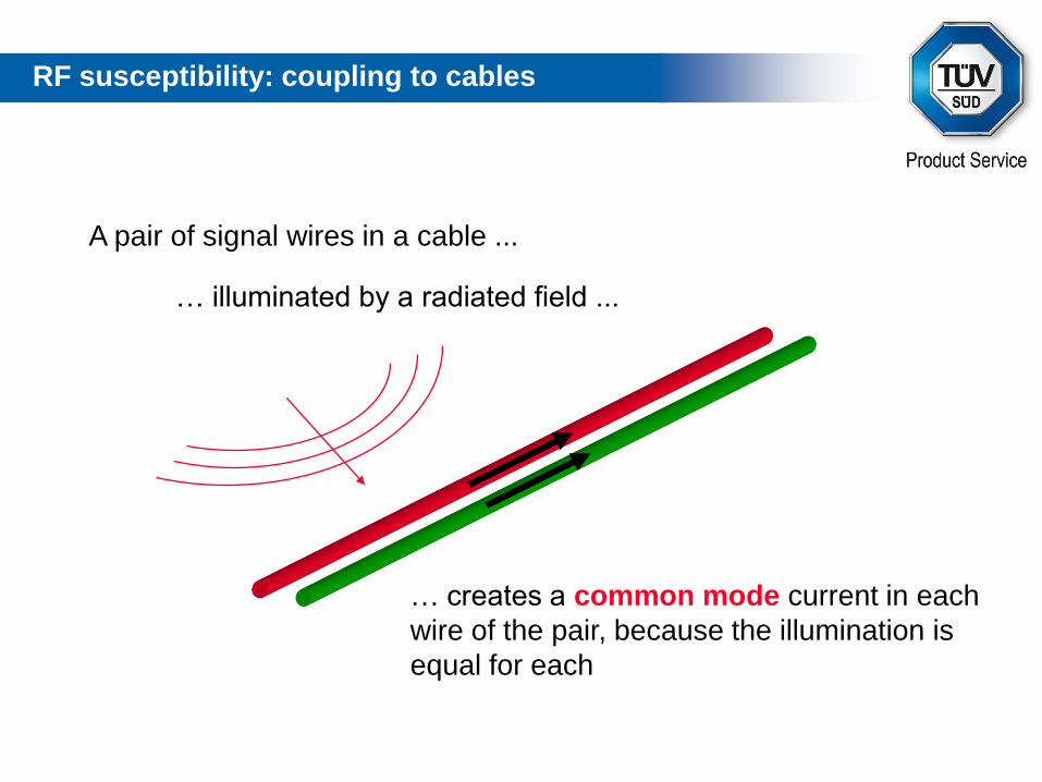
RF susceptibility: coupling to cables
A pair of signal wires in a cable ...
… illuminated by a radiated field ...
… creates a common mode current in each
wire of the pair, because the illumination is
equal for each
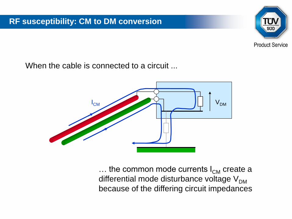
RF susceptibility: CM to DM conversion
When the cable is connected to a circuit ...
VDM
… the common mode currents ICM create a
differential mode disturbance voltage VDM
because of the differing circuit impedances
ICM
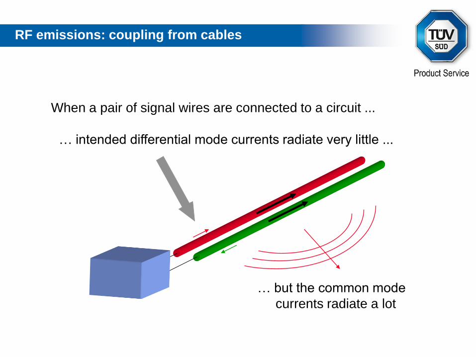
RF emissions: coupling from cables
When a pair of signal wires are connected to a circuit ...
… but the common mode
currents radiate a lot
… intended differential mode currents radiate very little ...
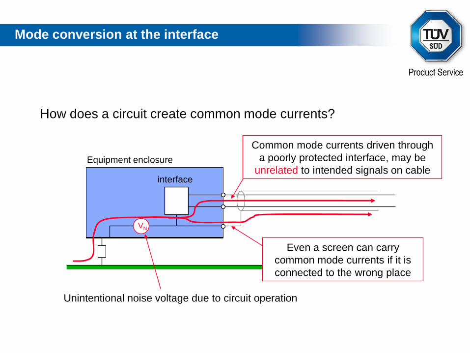
Mode conversion at the interface
How does a circuit create common mode currents?
interface
Equipment enclosure
VN
Unintentional noise voltage due to circuit operation
Common mode currents driven through
a poorly protected interface, may be
unrelated to intended signals on cable
Even a screen can carry
common mode currents if it is
connected to the wrong place
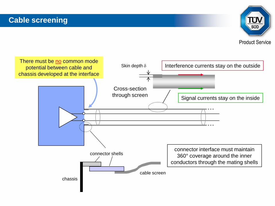
Cable screening
Cross-section
through screen
Skin depth d Interference currents stay on the outside
Signal currents stay on the inside
chassis
connector shells
cable screen
connector interface must maintain
360° coverage around the inner
conductors through the mating shells
There must be no common mode
potential between cable and
chassis developed at the interface
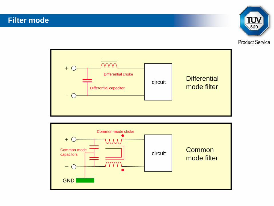
Filter mode
+
–
Differential
mode filtercircuit
+
–
Common
mode filtercircuit
GND
Differential choke
Differential capacitor
Common-mode choke
Common-mode
capacitors
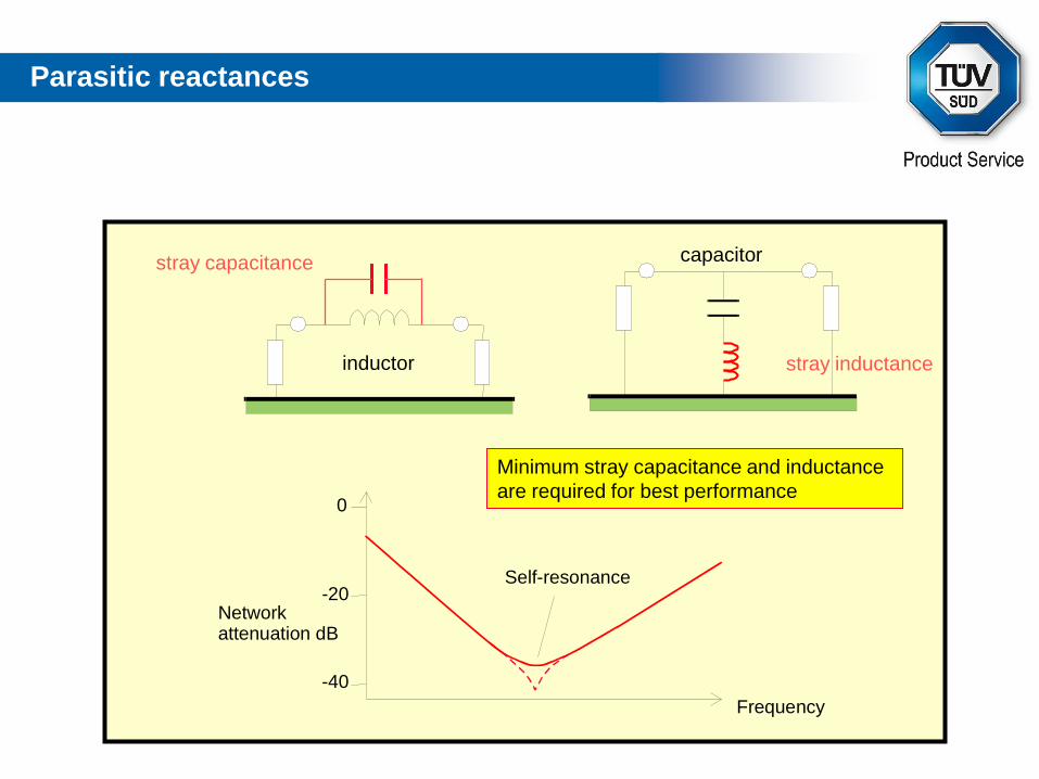
Parasitic reactances
Networkattenuation dB
0
-20
-40
Frequency
Self-resonance
inductor
stray capacitance capacitor
stray inductance
Minimum stray capacitance and inductance
are required for best performance
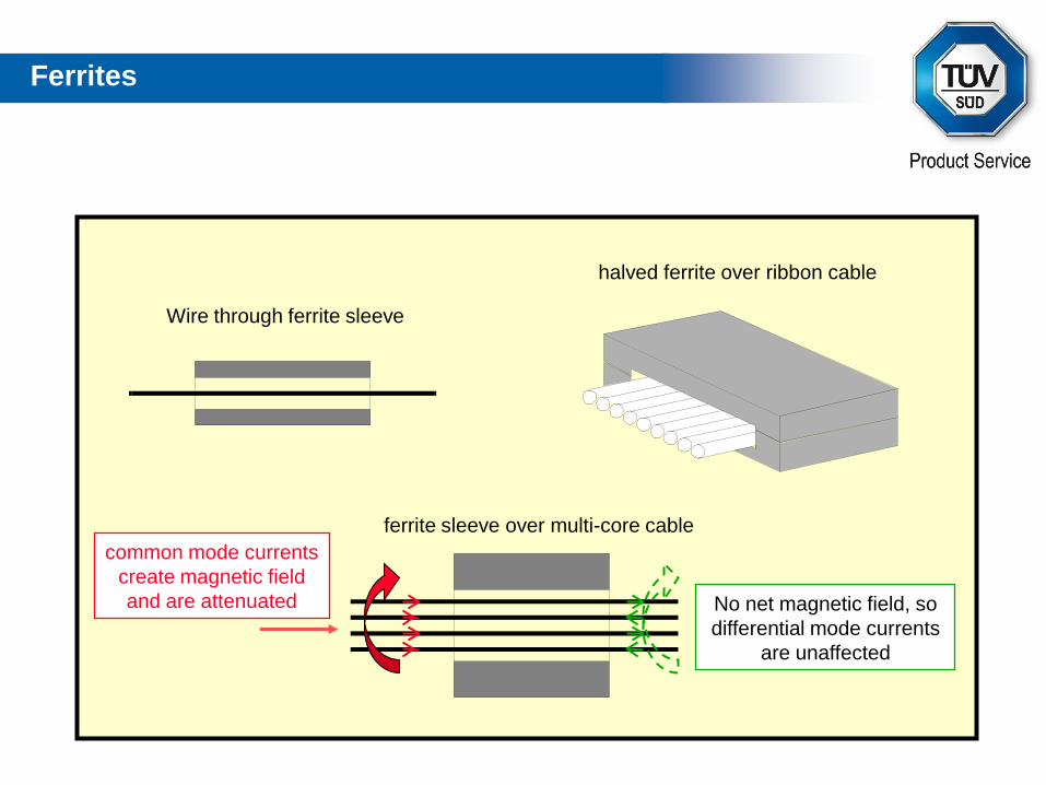
Ferrites
Wire through ferrite sleeve
halved ferrite over ribbon cable
ferrite sleeve over multi-core cable
common mode currents
create magnetic field
and are attenuated No net magnetic field, so
differential mode currents
are unaffected
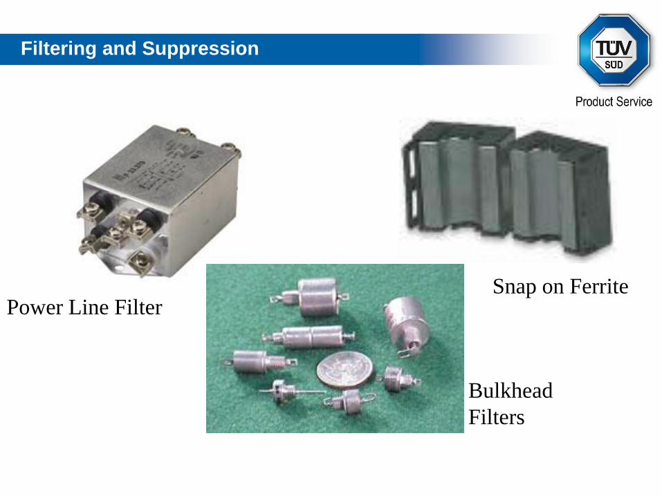
Filtering and Suppression
Snap on FerritePower Line Filter
Bulkhead
Filters
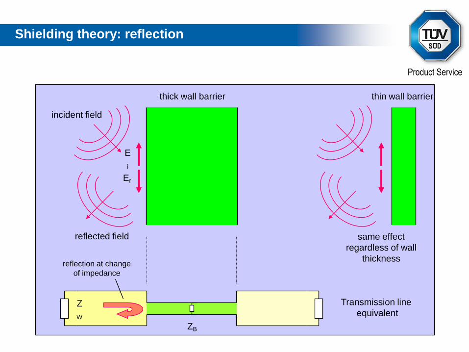
Shielding theory: reflection
thick wall barrier thin wall barrier
Transmission line
equivalentZ
W
ZB
reflection at change
of impedance
incident field
reflected field
E
i
Er
same effect
regardless of wall
thickness
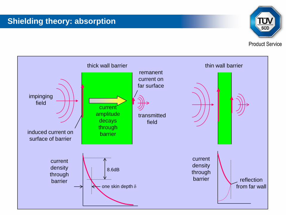
Shielding theory: absorption
thick wall barrier thin wall barrier
current
density
through
barrier reflection
from far wall
impinging
field
induced current on
surface of barrier
current
amplitude
decays
through
barrier
transmitted
field
remanent
current on
far surface
current
density
through
barrierone skin depth d
8.6dB
Limitations on theory
• Real enclosures are not infinite in extent
• they have imperfections compared to a
perfect Faraday cage:
– they have apertures, seams and joints
– they are often an irregular shape
– there are enclosure resonances
– they include components with complex
internal layout
• unknown incident wave impedance
• unknown internal wave impedance
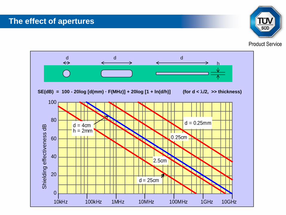
The effect of apertures
SE(dB) = 100 - 20log [d(mm) · F(MHz)] + 20log [1 + ln(d/h)] (for d < l/2, >> thickness)
h
d d d
1GHz 10GHz100MHz10MHz1MHz100kHz10kHz
0
20
40
60
80
100
Sh
ield
ing e
ffe
ctive
ne
ss d
B
d = 25cm
2.5cm
0.25cm
d = 0.25mmd = 4cmh = 2mm
Shie
ldin
g e
ffectiveness d
B
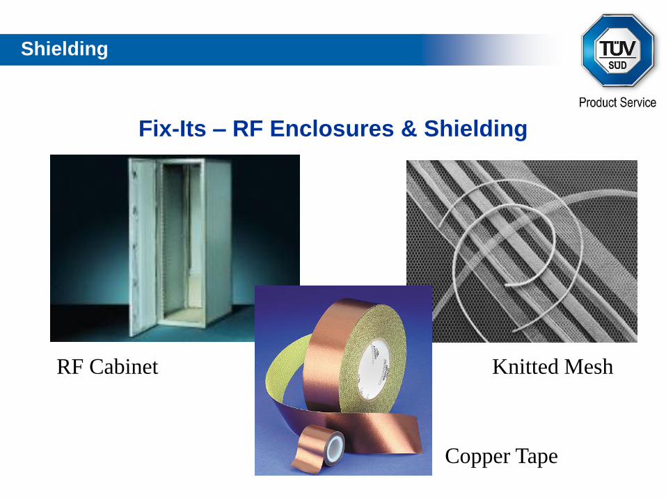
Shielding
Fix-Its – RF Enclosures & Shielding
Knitted MeshRF Cabinet
Copper Tape
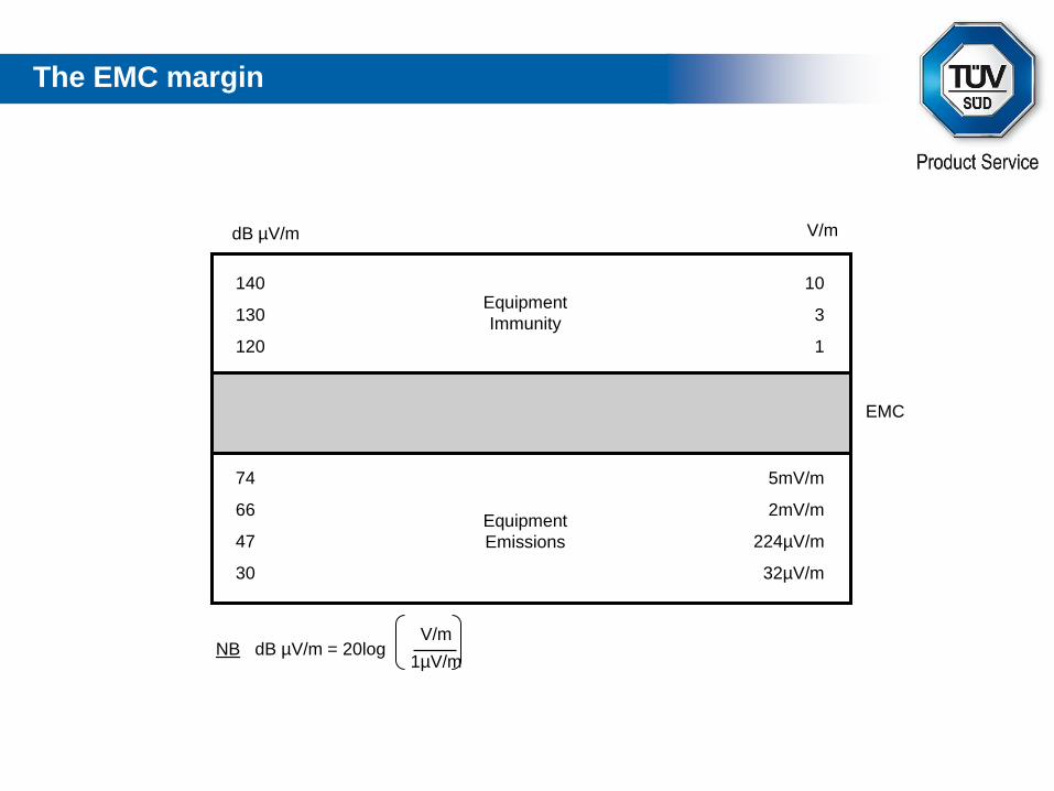
Equipment
Immunity
Equipment
Emissions
140
130
120
10
3
1
EMC
74
66
47
30
5mV/m
2mV/m
224µV/m
32µV/m
NB dB µV/m = 20log
dB µV/m V/m
V/m
1µV/m
The EMC margin

Andy Lawson
Technical Supervisor, Industry EMC, TÜV SÜD Product Service
Tel: +44(0)1489 558100
ww.tuvps.co.uk