Embed Size (px)
Citation preview

A Beam Tracing Method withPrecise Antialiasing for Polyhedral Scenes
Djamchid GHAZANFARPOUR and Jean-Marc HASENFRATZ
Laboratoire MSI - Université de LimogesE.N.S.I.L.
Technopole F87068 LIMOGES Cedex, Francee-mails: [email protected] [email protected]
1. IntroductionRay tracing is one of the most interesting algorithms in computer graphics to generate realistic images
of 3D scenes. It is able to simulate various optic phenomena such as shadows, reflections and refractions.However, ray tracing is in essence a point sampling approach (the scene is sampled at the centre of eachscreen pixel) and thus is prone to the well-known aliasing problems (image 1). This is also the case of manyother visualization algorithms such as the popular z-buffer [1]. We recall that aliasiasing appears essentialyin the following forms :
• jagged edges;• discontinuity and/or flash of small objects;• moiré patterns on textured objects.
Aliasing is a crucial problem for ray tracers because classical antialiasing techniques are inefficient in somecases, in particular for small objects and shadows.
There are two popular antialiasing approaches for ray tracing that use pixel subdivisions and low-passfilterings:
• conventional over-sampling [2, 3] … which is simple and not very expensive;• stochastic over-sampling [4-6] … whose main advantage is not antialiasing but the simulation of
special optical phenomena such as motion blur that cannot be obtained directly [4].All these over-sampling methods are generally efficient for detecting and antialiasing jaggies but inefficientfor other aliasing cases because they cannot guarantee the detection of small objects and small shadows(images 1). In fact, there is no correct way to detect small objects and small shadows that slip through theinfinitesimal rays or even sub-rays. In order to detect all these problems, the infinitesimal ray concept mustbe replaced inevitably by a “ray” having some volume called a beam.
Beam tracing [7-11] can be considered as an alternative to ray tracing. The antialiasing property ofbeam tracing is very interesting because it is probably the only approach that can produce a generalantialiasing. However, the main goal of most beam tracing methods has not often been the improvement ofantialiasing.
The method presented here describes a high quality beam tracer with general and precise antialiasingthat extends and improves on the beam tracer for polygonal scenes previously developed by one of theauthors [11].
In particular, scenes are modeled by polyhedra instead of polygons, an important improvement basedon regular spatial subdivision is used and non-punctual light sources with soft shadows, without anystochastic sampling, are possible.
In our approach the recursive image space subdivision principle is similar to the one used to removehidden surfaces in [12]. The beams have pyramidal, semi-pyramidal, or pseudo semi-pyramidal shapes. Theymay appear similar to the beams of [8] but, here, no complex computation of beam-object intersections orof 3D polygon clippings is necessary. This gives out the main advantage of this method over the others ofthe beam tracing family. In addition to a substantial run time reduction, the absence of complexcomputations as beam-object intersections or 3D clippings, allows to extend this approach to some non-polyhedral scenes such as CSG ones.

Computer & Graphics Vol 22, No 1 pp 103-115, 1998
2
In this method, beams can be considered just as bounding volumes essentially used for the detectionof aliased edges, small objects and shadows. After the detection of the aliased regions, a ray tracing with anadaptive over-sampling and a low-pass filtering is used for rendering the regions with antialiasing. Textureantialiasing is handled separately with no over-sampling as we will see later in section 3.2.2.
All aliasing problems, including small objects and small shadows, are precisely detected and solved.Refractions are free from linear approximation or complex computations usually used in similar beamtracers [8, 10]. Soft shadows due to non-punctual light sources can be produced with no stochastic sampling.Well-known improvements of classical ray tracing (spatial subdivisions and hierarchical bounding volumes)are entirely compatible with this beam tracer.
The first part of this paper concerns beam tracing of polyhedral scenes with reflection, refraction andhard shadows. The second one proposes a technique to simulate soft shadows, and the last part presentssome results and time comparisons.
2. Method descriptionIn a previous paper [11], we developed a beam tracing method for scenes modeled by any kind of
polygons. Now, we study a beam tracing method for scenes modeled by convex polyhedra. The choice ofconvex polyhedra, corresponding to a great number of scenes, is motivated by a computational argument. Infact, our approach is compatible with concave polyhedra but the detection of aliased regions, in the case ofconvex polyhedra, is faster because simpler tests can be used to determine the position of objects relative tobeams.
The beam tracer is improved by the implementation of spatial subdivision in order to take advantageof the spatial coherence. Two types of spatial subdivisions can be used: regular [13-15] … and irregular [16-18]. In the general case, we did not find any significant advantage between these two approaches for raytracing in the literature. For example, the conclusion of a recent paper [19] comparing these two kinds ofsubdivisions is: « A general statement concerning the question whether ray-generators for octrees lead tobetter results then ray-generators for uniform subdivisions cannot be made. This will always depend on thechosen scene ». In addition, the implementation of the regular subdivision is easier than the implementationof the irregular subdivision in the case of beam tracing. For these reasons, we chose a regular spatialsubdivision to improve our beam tracer.
We will see principles and conceptual step details of this beam tracer in the following sections.
2.1 Detection of aliased regions
The beams are used to determine two types of image regions:• uniform regions with no aliasing problem concerning jaggies, small objects and small shadows
(remember that texture antialiasing problems are handled separately);• ambiguous regions with possible aliasing problems.
2.1.1 Case of opaque and non-reflecting objects
Vision beamsOur method is based on an adaptive recursive subdivision of the image space. First, a region
corresponding to the entire screen and its associated vision beam are tested and recursively subdivided untileither an uniform region is obtained or the pixel subdivision limit is reached. A vision beam (primary beam)is a pyramid, traced from the eye to the scene (figure 1). This pyramid is defined by the eye (its apex) andfour rays (its edges) passing through the corners of an image region. If the region is ambiguous, it issubdivided in four and four new sub-pyramids are traced.
To determine the type of an image region (uniform or ambiguous), we attach to each edge of its beamthe first intersected object†, if this object exists. We can consider four cases of edge-object intersections:
† The computation of edge-object intersections is improved by the use of a classical spatial regular subdivision.
Computer & Graphics Vol 22, No 1 pp 103-115, 1998
3
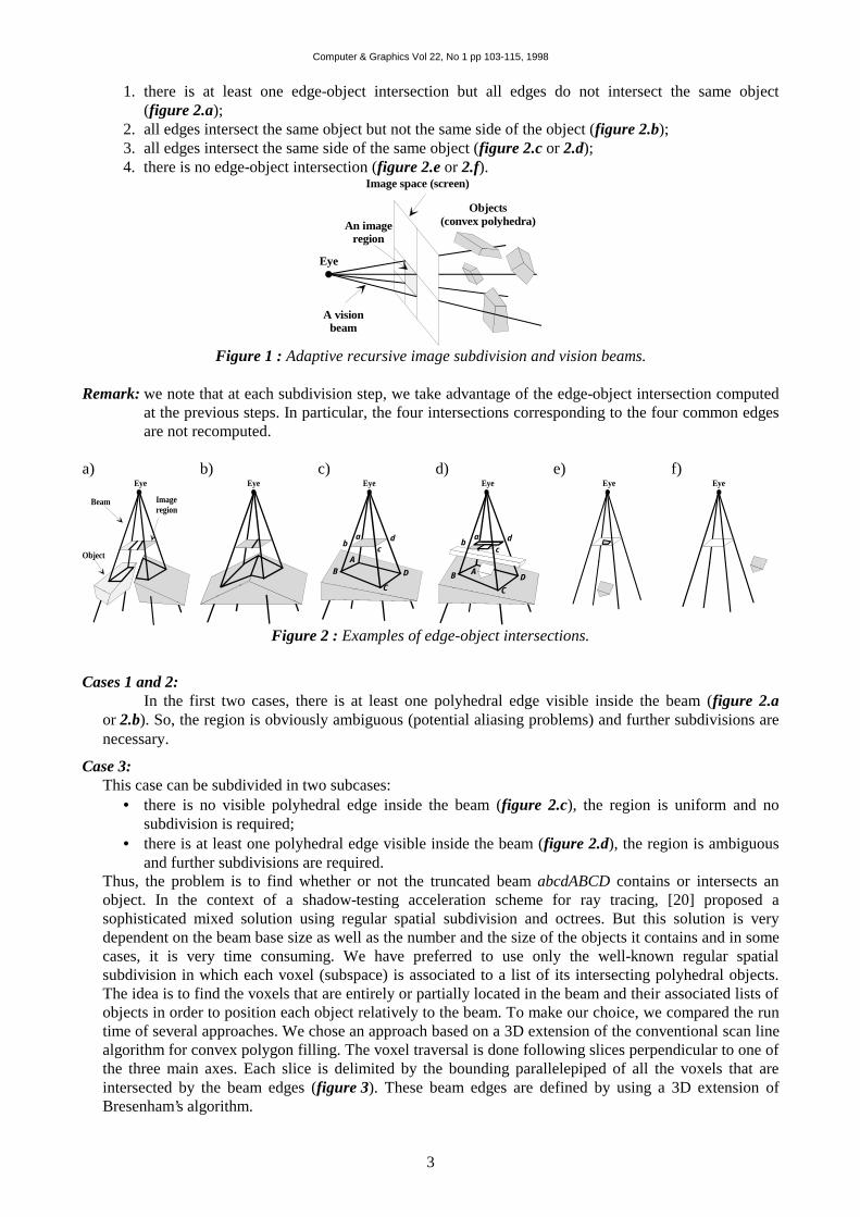
1. there is at least one edge-object intersection but all edges do not intersect the same object(figure 2.a);
2. all edges intersect the same object but not the same side of the object (figure 2.b);3. all edges intersect the same side of the same object (figure 2.c or 2.d);4. there is no edge-object intersection (figure 2.e or 2.f).
An imageregion
A visionbeam
Objects(convex polyhedra)
Image space (screen)
Eye
Figure 1 : Adaptive recursive image subdivision and vision beams.
Remark: we note that at each subdivision step, we take advantage of the edge-object intersection computedat the previous steps. In particular, the four intersections corresponding to the four common edgesare not recomputed.
a)
Imageregion
Beam
Object
Eyeb)
Eyec)
Eye
ab
cd
C
D
AB
d)
F
DAB
C
ab
cd
Eyee)
Eyef)
Eye
Figure 2 : Examples of edge-object intersections.
Cases 1 and 2:In the first two cases, there is at least one polyhedral edge visible inside the beam (figure 2.a
or 2.b). So, the region is obviously ambiguous (potential aliasing problems) and further subdivisions arenecessary.
Case 3:This case can be subdivided in two subcases:
• there is no visible polyhedral edge inside the beam (figure 2.c), the region is uniform and nosubdivision is required;
• there is at least one polyhedral edge visible inside the beam (figure 2.d), the region is ambiguousand further subdivisions are required.
Thus, the problem is to find whether or not the truncated beam abcdABCD contains or intersects anobject. In the context of a shadow-testing acceleration scheme for ray tracing, [20] proposed asophisticated mixed solution using regular spatial subdivision and octrees. But this solution is verydependent on the beam base size as well as the number and the size of the objects it contains and in somecases, it is very time consuming. We have preferred to use only the well-known regular spatialsubdivision in which each voxel (subspace) is associated to a list of its intersecting polyhedral objects.The idea is to find the voxels that are entirely or partially located in the beam and their associated lists ofobjects in order to position each object relatively to the beam. To make our choice, we compared the runtime of several approaches. We chose an approach based on a 3D extension of the conventional scan linealgorithm for convex polygon filling. The voxel traversal is done following slices perpendicular to one ofthe three main axes. Each slice is delimited by the bounding parallelepiped of all the voxels that areintersected by the beam edges (figure 3). These beam edges are defined by using a 3D extension ofBresenham’s algorithm.

Computer & Graphics Vol 22, No 1 pp 103-115, 1998
4
Image region
Truncated beam
Parallelepipedbouding the slice
a b
cd
A
B
C
D
a voxel intersectedby the beam edge
Figure 3: Slice delimited by the bounding parallelepiped of all voxels intersected by the beam edges.
For each traversed voxel, we position its associated objects relatively to the beam. To determine that anobject is outside a beam, we use the following rule: if there is a plane that separates the space in a half-space that contains completely the beam and a half-space that contains completely the object, then theobject is outside the beam. Judicious separating planes are:
• the image plane (figure 4.a),
• the plane containing ABCD, (figure 4.b),
• one of the four sides planes of the beam (figure 4.c),
• all planes tangent to a beam edge that contains re and
r r rv E e= × (figure 4.d) where
rE is a vector
parallel to one edge direction of the polyhedron.
a)
Beam
Image plane
A
B
C
D
abc d Object
b)
Intersected plane
AB
CD
c)
Beam side plane
d)
v
E
Tangent plane
Figure 4: Judicious separating planes.
All these planes are considered in the order of the enumeration. If one of these planes matches theprevious rule, the considered object is outside the beam and we test the next object. If all consideredobjects are outside the beam, there is no aliasing problem (figure 2.c), the region is uniform and no moresubdivision is required. In other cases, the beam may contain or intersect an object, so the regioncorresponding to the beam is considered as ambiguous and more subdivisions are required (figure 2.d).
Case 4:This case (figure 2.e or 2.f) is similar to the previous one (figure 2.c or 2.d) if we can “bound” the beam.For this goal, we chose a virtual plane that represents the scene “background”. This virtual plane isparallel to the image plane and contains the furthest corner of the regular spatial subdivision from the eye(figure 5).

Computer & Graphics Vol 22, No 1 pp 103-115, 1998
5
Image plane
Virtual background plan
Regular grid ofspatial subdivision
EyeFigure 5: 2D representation of the regular spatial
subdivision and the virtual background plane.
Shadow beams:When the previous tests lead to an uniform region, then the corresponding vision beam entails no
further subdivision. This means that only one side of a polyhedron is visible in the beam. The intersectionABCD of this side with the beam (figure 6) is used to produce a shadow beam (secondary beam). A shadowbeam is a pyramid that has ABCD as its intersection and a light source S as its apex (figure 6). The visibilityof ABCD from S is determined by new tests. These tests are similar to those used for the vision beam. Weneed to distinguish among the three following cases:
1. ABCD is entirely visible from S and thus directly illuminated;2. ABCD is entirely hidden from S and thus inside the shadow;3. ABCD is partially visible from S.
In the first two unambiguous cases, no subdivision is required and a newlight source, if it exists, with its corresponding beam, is tested. In thethird case, the image region corresponding to ABCD is subdivided. Wemay notice that, in this case, there is no visibility test to perform for thenew four vision sub-beams. We must only test the produced shadowsub-beams to determine the visibility of their intersections. Finally, aregion is considered uniform in this step if its vision beam and all itsshadow beams are uniform. We remark that the tests used for shadowbeams are simpler than those used for vision beams. In fact, for anobject placed between S and ABCD and intersecting the four edges ofthe shadow beam (see cases 2 and 3 of vision beam and figure 2.b, 2.cand 2.d), the previous tests concerning the detection of an other objectpossibly partially or entirely inside the beam are not necessary.
S
Image regionLight source
Shadow beam
Primary bea
B
CD
A
Eye
Figure 6: Shadow beam.
2.1.2 Case of reflected and refracted objects
We first studied principles of beam construction and adaptive recursive subdivision for opaquepolyhedra without reflection. The natural extensions of this beam tracer to the cases of reflecting andrefracting polyhedra will now be studied. These cases concern only regions detected as uniform by visionand shadow beams. For the other regions, where the limit of subdivision is achieved, we go directly to therendering process (see section 3.2).
Reflections:The well-known concept of virtual eye, as presented among others
in [8], is used to compute reflection effects. The virtual eye is the pointsymmetric to the eye relatively to a reflecting side R of a polyhedron(figure 7). If ABCD is the intersection of a vision beam with this side, anew pyramidal volume can be produced with the virtual eye as its apexand ABCD as its intersection (figure 7). The reflection beam is the upperside of this volume corresponding to a semi-pyramid (figure 7). Thissemi-pyramid is tested in a similar way as a vision beams. If at least onepolyhedron edge is visible (entirely or partially) inside the reflectingbeam, then the beam subdivision is performed.
Reflectingbeam
Virtual eye
A
B
CDR
Eye
Figure 7: Reflection beam.

Computer & Graphics Vol 22, No 1 pp 103-115, 1998
6
Refractions:Because refraction is not a linear transformation, computing a realistic refraction is a task that cannot
be handled correctly using most existing beam tracing algorithms. For example, refraction computations areapproximations when using the method developed in [8], in which two different refraction cases areconsidered. In the first case, the eye is supposed to be positioned far away from the scene; thereforerefracted rays are almost parallel. In the second case, the angles of the rays are less than a certain value; inthis limited case the refraction can be considered as a linear transformation. So, refracted rays are supposedto converge to a certain point called virtual eye. A more precise, but more complicated refractiondetermination is developed in [10]. We use a different approach in order to avoid these approximations andcomplex computations.
Consider ABCD, the intersection of a vision beam with a refracting polyhedron (figure 8.a) and therefracted rays r1 , r2, r3 and r4 in A, B, C and D (figure 8.b). Each edge of ABCD with a refracted ray canform a plane. For example, there are two refracted rays r2 and r3 for edge BC and two potential planes P1and P2 produced by BC and one of the rays (figure 8.b). One of the planes (P2 in this example) is betweenABCD and the other one. We choose the outer plane (P1 in this example) and the three other similar planesto construct a refraction volume. Thus, a refraction beam (pseudo semi-pyramid) can be produced by ABCDedges and the four planes (figure 8.c). This beam contains all the refracted rays concerned by ABCD. Thisbeam is tested and may be subdivided in the same way as the previous case. We note that we use at leasttwo refraction beams to traverse the polyhedron (figure 8.d). More beams are used if the beam exits bymore than one face because of an edge aliasing problem (figure 8.e). As with previous types of beams, thisrefraction beam can be considered as a bounding volume for refracted rays and it is only used to detectpossible aliased corresponding regions, but the color computations only depend on the refracted rays in thesame way as the classical ray tracing (section 3.2). So, with our beam tracer refraction computations are asprecise as the ray tracers.
a)
Refractedregion
A
B C
D
Eye
Refractedpolyhedron
b)Eye
Refractedray
One plane side ofthe refracted beam
P2 3r
4r1r
P1
A
BC
D
r2
c)Eye
Refracted beam
A
BC
D
r2P1
d)
A
B C
D
Eye
Refractedbeams
e)
A
B C
D
Eye
Refractedbeam
Edge aliasing problem
Figure 8: a: Refraction region, b and c: plane selection for construction ofrefraction beam, d and e: multiple refraction beams.
2.2 Rendering
2.2.1 Color computations
The goal of the previous sections was the detection of edges, small objects and small shadowscorresponding to ambiguous regions and an adaptive recursive subdivision of these regions until uniformregions or the pixel subdivision limit were achieved. A region is detected as uniform when all correspondingbeams are tested and when there is no visibility ambiguity inside of them. In order to reach this goal, wehave used a variety of beams and have mentioned that these beams are bounding volumes only used todetermine the type (ambiguous or uniform) of regions. The color computation in an image region isaccomplished by ray tracing. In addition, ray-object intersection computations are improved in this casebecause intersected objects are already known by the help of associated region beams. Two kinds of regionscan be distinguished: regions greater than one screen pixel, regions smaller than one pixel.
In the first case, an uniform region corresponds to one or several pixels. Four rays passing througheach pixel corner are traced. We remark that with this method, each ray is common to four neighbour pixelsand it is not actually more expensive than tracing rays through pixels centres. The color of a pixel is theaverage of colors achieved by the four rays. There are two advantages when using four rays per pixel insteadof one as in the case for the ray tracing. The first one is a better information representation that can avoid

Computer & Graphics Vol 22, No 1 pp 103-115, 1998
7
minor aliasing problems as it can be the case with specular reflections. The second one is a more natural andeasier implementation of the algorithm specially with texture antialiasing (section 3.2.2).
In the second case, we trace a ray through the middle of the sub-pixel. The final color of a screenpixel is the weighted average of the sub-pixels inside the low-pass filter kernel.
2.2.2 Texture antialiasing
Texture mapping as well as 3D texturing in real cases do not fail to produce a texture compressiondue to perspective projection [21]. Texture compression corresponds to an increase of texture highfrequencies and consequently aliasing (specially well-known “moiré” patterns). When using ray or beamtracing methods, there are two possible approaches for texturing with antialiasing.
The usual approach is over-sampling in which pixel subdivision is required not for jagged edge pixelsor small objects but inside textured pixels. Two fundamental disadvantages of this approach are persistenceof some “moiré” patterns and considerable increase of run time. The first problem is due to the fact that evenif an important subdivision rate is used, “moiré” patterns are always noticeable when texture is highlycompressed. Run time increase is due to pixel subdivision with one ray per sub-pixel and consequently agreater number of ray-object intersection calculations and texture access.
In the case of texture mapping, efficient prefiltering methods based on the well-known pyramidalstructure texture mapping [22] are more interesting than over-sampling. These methods use prefilteredversions of 2D texture corresponding to all possible texture compressions. We can use a method of this type[23] in which the local texture compression in each image pixel is used to choose the correspondingprefiltered texture versions. The notion of texture compression can also be used in the case of some 3Dtextures as presented in [24, 25]. Our beam tracer is well adapted to these 2D or 3D texturing methodsbecause the texture compression can be achieved without any additional costs (figure 9), simply bycomparing the size of an image pixel (abcd) to the size of its corresponding pyramid intersection with atextured polyhedron side (ABCD).
One imagepixel
a
b
cd
A
D
B
C
Textured polyhedron side
Figure 9: Texture compression.
3. Extending beam tracer to compute soft shadowsAs described in [26], several techniques exist to compute soft shadows:
• classical techniques based on stochastic ray tracing as [4] are very expensive for large lightsources;
• the cone tracing developed in [7] provides soft shadows for spherical light sources but requirescomplex computations of cone-object intersections.
In this section, we present a method using spherical light sources with our beam tracer to computerealistic, but not real, soft shadows effects. Soft shadows obtained by this method are graphically similar tothose obtained by a stochastic ray tracing for small light sources. In addition, in our approach, very largesources can be used to produce realistic soft shadows.
3.1 Basic technique
The effects of soft shadows on a region are due to the absorption of a portion of the light sourceenergy sent by a non punctual light source toward an object region. Our approach has two steps:
• The first step is to detect the regions located in soft shadows. We use particular beams (seesection 4.2) to identify the regions entirely located in the light, those entirely located in the shadowand those located in the soft shadow.

Computer & Graphics Vol 22, No 1 pp 103-115, 1998
8
• The second step is to approximate for each pixel of a soft shadow region the amount of receivedlight energy. We use a beam which has the pixel as its base and contains the light source.
3.2 Detecting soft shadow regions
The idea is similar to the case of punctual light sources: we use a beam to determine problematicregions (regions in soft shadows). To determine these soft shadow regions, for each region ABCD(figure 10.a) that was detected as uniform by the vision, reflection and refraction beams, we build a softshadow beam. The base of this beam is ABCD, its four sides are defined as tangent planes to the sphericallight source and its top is the plane P (figure 10.a). P is a plane tangent to the spherical light source with anormal vector n approximately (figure 11) directed toward the centre of ABCD.
Such a beam is an approximation of the light beam coming from the source and reaching the ABCDregion. Although the soft shadow beam is slightly larger than the beam emitted in reality, our graphicalresults demonstrate that it fits to a realistic rendering of soft shadows.
The soft shadow beam is then used, with similar tests as those used for the vision beams, to determinethe type of a region ABCD: entirely in the shadow, entirely lighted or in the soft shadow.In the first two cases, the region is considered uniform and no subdivisions are necessary. For a lightedregion (figure 13.a), pixel rendering computations are similar to the point light source (section 3.2.1). Infact, in this case, the spherical light source is approximated by a point source of the same energy placed inthe center of the sphere. For a region entirely in shadow (figure 13.d), pixel rendering computations areidentical to the point light source (section 3.2.1).In the third case, the region is subdivided. The recursive subdivision technique of the region and itscorresponding soft shadow beams are similar to the case of vision beam. The base of each sub-beam is oneof the four sub-regions of ABCD, its sides are defined as tangent planes to the spherical source and its top P’(figure 10.b). P’ is obtained in the same manner as the plane P. The recursive subdivision is continued untila uniform (entirely lighted or entirely shadow) region is obtained or the size of one pixel is reached.
Image region
Spherical lightsource
Soft shadow beam
C
D
Vision beam
B
n P
A
Eye
P’
A
C
D
B
Spherical lightsource
Soft shadow sub-beam
Figure 10.a: Shadow beam. Figure 10.b: Subdivision of a shadow beam ona region strictly larger than one pixel.
C
D
B
A
a
b
c
d
e
Figure 11: Approximation of the center of apolygon ABCD. a (resp. b, c and d) is the
middle of AB (resp. BC , CD and DA ). The
center e is define as the intersection of ac and
bd .

Computer & Graphics Vol 22, No 1 pp 103-115, 1998
9
3.3 Portion of light received by the pixel
We are now left with soft shadow regions that are equivalent to apixel, and for which we can thus evaluate the portion of receivedlight: we recursively divide the beam into four sub-beams (figure 12)until we reach an uniform region or the limit of pixel subdivision.The base of a sub-beam is defined like the previous case, its sides aredefined as to divide P’ in four polygons which have approximately‡
the same surface (figure 12). For example, we consider the case ofthe partially illuminated pixel of figure 13.b and its correspondingbeam. This pixel and P’ are recursively subdivided. Finally, theillumination of the pixel is determined as the sum of illuminated sub-pixels surfaces. This sum approximates the portion of light receivedby the pixel. Figure 13 shows the different steps of a light softtransition: from an entirely illuminate pixel to a pixel entirely inshadow.
A
C
D
B
P’Spherical light
source
Soft shadow sub-beam
Figure 12: Subdivision of ashadow beam on a region
smaller than one pixel
a)
P’
Soft shadow beamSpherical
light source
Lighted pixel
Object
Pixel consedered
Pixel illumination
b)
Soft shadowsub-beam
Partialy lightedpixel
P’
c)
P’
Partialy lightedpixel
d)
P’
Shadow pixel
Pixel entirely lighted The light partially reachesthe pixel.
The light partially reaches thepixel.
Pixel entirely in shadow
Figure 13: Soft shadow example in 2D: illumination of consecutive pixels
We note that for the smallest sub-pixels (limit of subdivision), the illumination computations aresimilar to the point light source (section 3.2.1). In fact, in this case, the spherical light source isapproximated by a point source of the same energy placed in the center of the top polygon (figure 11) of thesoft shadow beam.
4. Results and comparisonsTo compare our beam tracing with the ray tracing, we have used four different test scenes. One scene
is produced automatically by random placement of 2060 cubes. Two other scenes are more realistic andrepresent a room (images 1 and 2) and a virtual town (image 3). The last scene represents seven pillars andis used for producing soft shadows (image 4).
4.1 Aliasing problems and special effects
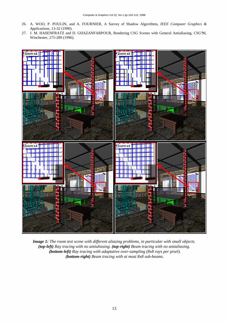
As we see in image 1, the problem of small objects and small shadows is entirely solved by our beamtracing. In fact, ray tracing algorithm cannot solve the problem even with an adaptive over-sampling(8x8 rays/pixel): some small objects and small shadows are missed. Image 2 shows different possibleeffects as reflection, refraction and soft shadows with our beam tracing. We remember that the refractionproduced by this method is as precise as the ray tracing algorithm (without approximations used with otherbeam tracers).
4.2 Computational time
For time comparisons, we have used two scenes: a random placed cubes (2060 polyhedra) and thevirtual town of image 3 (1519 polyhedra) in the two following cases:
‡ To divide a polygon into four regions with approximately the same surface, we use the definition of the center of a polygonproposed in figure 11.
Computer & Graphics Vol 22, No 1 pp 103-115, 1998
10
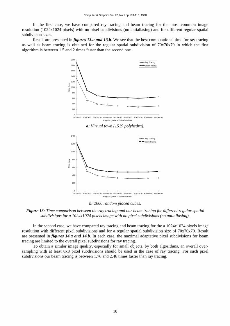
In the first case, we have compared ray tracing and beam tracing for the most common imageresolution (1024x1024 pixels) with no pixel subdivisions (no antialiasing) and for different regular spatialsubdivision sizes.
Result are presented in figures 13.a and 13.b. We see that the best computational time for ray tracingas well as beam tracing is obtained for the regular spatial subdivision of 70x70x70 in which the firstalgorithm is between 1.5 and 2 times faster than the second one.
0
200
400
600
800
1000
1200
1400
1600
1800
2000
10x10x10 20x20x20 30x30x30 40x40x40 50x50x50 60x60x60 70x70x70 80x80x80 90x90x90
Regular spatial subdivision sizes
Tim
e [s
ec]
Ray Tracing
Beam Tracing
a: Virtual town (1519 polyhedra).
0
200
400
600
800
1000
1200
1400
10x10x10 20x20x20 30x30x30 40x40x40 50x50x50 60x60x60 70x70x70 80x80x80 90x90x90
Regular spatial subdivision sizes
Tim
e [s
ec]
Ray Tracing
Beam Tracing
b: 2060 random placed cubes.
Figure 13: Time comparison between the ray tracing and our beam tracing for different regular spatialsubdivisions for a 1024x1024 pixels image with no pixel subdivisions (no antialiasing).
In the second case, we have compared ray tracing and beam tracing for the a 1024x1024 pixels imageresolution with different pixel subdivisions and for a regular spatial subdivision size of 70x70x70. Resultare presented in figures 14.a and 14.b. In each case, the maximal adaptative pixel subdivisions for beamtracing are limited to the overall pixel subdivisions for ray tracing.
To obtain a similar image quality, especially for small objects, by both algorithms, an overall over-sampling with at least 8x8 pixel subdivisions should be used in the case of ray tracing. For such pixelsubdivisions our beam tracing is between 1.76 and 2.46 times faster than ray tracing.

Computer & Graphics Vol 22, No 1 pp 103-115, 1998
11
0
1000
2000
3000
4000
5000
6000
7000
8000
9000
1x1 2x2 4x4 8x8Regular spatial subdivision sizes
Tim
e [s
ec]
Ray Tracing
Beam Tracing
a: Virtual town (1519 polyhedra).
0
1000
2000
3000
4000
5000
6000
7000
8000
9000
10000
1x1 2x2 4x4 8x8Regular spatial subdivision sizes
Tim
e [s
ec]
Ray Tracing
Beam Tracing
b: 2060 random placed cubes.
Figure 14: Time comparison between the ray tracing and our beam tracing for a 70x70x70 regular spatialsubdivision and a 1024x1024 pixels image with different pixel subdivisions.
4.3 Soft shadows
With small volumic light sources, there is no graphical difference between our beam tracing and thestochastic ray tracing but our beam tracing is more time consuming. With large volumic light sources, thestochastic ray tracing uses a lot of rays to produce good quality soft shadows. So, it becomes too expensiveto be used in this case but our beam tracing can produce good quality soft shadows (image 4) with a morereasonable cost.
5. Conclusion and future worksThis method, which can be considered as a beam-ray tracing with adaptive image subdivisions, is an
efficient technique with general and robust antialiasing for polyhedral scenes. Particularly, small objects andsmall shadows are detected and processed precisely. Usual linear approximations or complex computationsfor refractions used in similar beam tracers are avoided with this method. Moreover, this method is welladapted to texture antialiasing with no over-sampling.
Pyramidal shape beams are used as a bounding volume to detect uniform and ambiguous regions.Opposite to other beam tracers, no explicit beam-object intersection computation is needed. This is the mainadvantage of our beam tracer compared to similar methods using complex beam-object intersection and 3Dclipping computations.
The extension of our beam tracing method to some non-polyhedral scenes is possible because of theabsence of explicit beam-object intersection computations. This is, in particular, the case of scenescomposed of geometric entities (spheres, cylinders, cones, ...) whose positions relative to pyramidal beams

Computer & Graphics Vol 22, No 1 pp 103-115, 1998
12
can be simply determined. Thus, our beam tracer can be extended to CSG scenes. An extension of our beamtracer for visualizing CSG scenes with no reflection and no refraction is developed in [27]. A generalextension of this method to CSG scenes including reflections and refractions is more complicated. It is thesubject of future works.
Our beam tracer, in which the beams are used as pyramidal bounding boxes, is well adapted todecrease the cost of form factor computations in radiosity algorithms. This is another subject of futureworks.
Acknowledgements: We would like to thank the Conseil Régional du Limousin for its financial support forthis work.
References
1. D. GHAZANFARPOUR and B. PEROCHE, Antialiasing by Successive Steps with a z-buffer, Proceedings ofEurographics’ 89, Hambourg, 235-244 (1989).
2. T. WHITTED, An Improved Illumination Model for Shaded Display, Communication of the ACM, 23(6), 343-349(1980).
3. J. ARGENCE, Antialiasing for Ray Tracing Using CSG Modelling, CG International’88, New Trends in ComputerGraphics, 199-208 (1988).
4. R. COOK, Stochastic Sampling in Computer Graphics, ACM Transactions on Graphics, 5(1), 51-72 (1986).5. D. MITCHELL, Generating Antialiased Images at Low Sampling Densities, Computer Graphics, 21(4), 65-72
(1987).6. J. PAINTER and K. SLOAN, Antialiased Ray Tracing by Adaptative Progressive Refinement, Computer
Graphics, 23(3), 281-288 (1989).7. J. AMANATIDES, Ray Tracing with Cones, Computer Graphics, 18(3), 129-135 (1984).8. P. HECKBERT and P. HANRAHAN, Beam Tracing Polygonal Objects, Computer Graphics, 18(3), 119-127
(1984).9. D. KIRK, The Simulation of Natural Features Using Cone Tracing, The Visual Computer, 3(2), 63-71 (1987).10. M. SHINYA, T. TAKAHASHI and S. NAITO, Principals and Applications of Pencil Tracing, Computer
Graphics, 21(4), 45-54 (1987).11. D. GHAZANFARPOUR, Visualisation réaliste par lancer de pyramides et subdivision adaptative, Proceedings of
MICAD 92, PARIS, 167-181 (1992).12. J. WARNOCK, A Hidden-Surface Algorithm for Computer Generated Half-Tone Pictures, University of Utah, TR
4-15, NTIS AD-753 671 (1969).13. A. FUJIMOTO, T. TANAKA, and K. IWATA, ARTS: Accelearted Ray-Tracing System, IEEE Jouranl of
Computer Graphics and Applications, 6(2), 16-26 (1986)14. J. AMANATIDES and A. WOO, A Fast Voxel Traversal Algorithm for Ray-Tracing, Proceedings of
Eurographics Conference, 27-38 (1987).15. J. G. CLEARY and G. WYVILL, Analysis of an Algorithm for Fast Ray Tracing Using Uniform Space
Subdivision, Journal of the Visual Computer, 4(1), 65-83 (1988).16. A. GLASSNER, Space Subdivision for Fast Ray Tracing, IEEE Journal of Computer Graphics and Applications,
4(5), 15-22 (1984).17. H. SAMET, Implementing Ray Tracing with Octrees and Neighbor Finding, Computers and Graphics, 4(13), 445-
460 (1989).18. J. SPACKMAN and P. WILLIS, The {SMART} Navigation of a Ray Through an Oct-Tree, Computers and
Graphics, 2(15), 185-194 (1991).19. R. ENDL and M. SOMMER, Classification of Ray-Generators in Uniform Subdivisions and Octrees for Ray
Tracing, Comupter Graphics Forum, 13(1), 3-19 (1994).20. H. K. CHOI, C. M. KYUNG, PYSHA - A Shadow-Testing Acceleration Scheme for Ray-Tracing, Computer-
Aided Design, 24(2), 93-104 (1992).21. D. GHAZANFARPOUR and B. PEROCHE, A High Quality Fitering Using Forward Texture Mapping, Computers
& Graphics, 15(4), 569-577 (1991).22. L. WILLIAMS, Pyramidal Parametrics, Computer Graphics, 17(3), 1-11 (1983).23. M. GANGNET and D. GHAZANFARPOUR, Techniques for Perspective Mapping of Plane Textures,
International Electronic Image Week, CESTA, Biarritz, 29-35 (1984).24. D. GHAZANFARPOUR and J. M. DISCHLER, Spectral Analysis for Automatic 3D Texture Generation,
Computers & Graphics, 19(3), 413-422 (1995).25. D. GHAZANFARPOUR, J.M. DISCHLER, Generation of 3D Texture Using Multiple 2D Models Analysis,
Computer Graphics Forum (N° spécial EUROGRAPHICS' 96), 15(3), 311-323 (1996).
Computer & Graphics Vol 22, No 1 pp 103-115, 1998
13
26. A. WOO, P. POULIN, and A. FOURNIER, A Survey of Shadow Algorithms, IEEE Computer Graphics &Applications, 13-32 (1990).
27. J. M. HASENFRATZ and D. GHAZANFARPOUR, Rendering CSG Scenes with General Antialiasing, CSG’96,Winchester, 275-289 (1996).
Image 1: The room test scene with different aliasing problems, in particular with small objects.(top-left) Ray tracing with no antialiasing. (top-right) Beam tracing with no antialiasing.
(bottom-left) Ray tracing with adaptative over-sampling (8x8 rays per pixel). (bottom-right) Beam tracing with at most 8x8 sub-beams.

Computer & Graphics Vol 22, No 1 pp 103-115, 1998
14
Image 2: Small objects detection and different possible effects produced by our beam tracing.
Image 3: The virtual town test scene produced by our beam tracing with a maximum of 8x8 sub-beams perpixel and with punctual light sources. This scene is used in the computational time comparison.

Computer & Graphics Vol 22, No 1 pp 103-115, 1998
15
Image 4: The seven pillars test scene with soft shadows in the case of a large light source.(top) Soft shadows with a stochastic ray tracing and 8x8 rays per pixel and its zoom.
(bottom) Soft shadows produced by the beam tracing with at most 8x8 sub-beams and its zoom.


![A Beam Tracing Method with Precise Antialiasing for ...cs6958/papers/CG98.pdf · A Beam Tracing Method with Precise Antialiasing for Polyhedral Scenes ... hidden surfaces in [12]](https://img.pdfslide.us/doc/110x75/5aeea2837f8b9a9031915a6c/a-beam-tracing-method-with-precise-antialiasing-for-cs6958paperscg98pdfa.jpg)