Embed Size (px)
Citation preview
HYDRAULIC INVESTIGATIONS 1T ~~ 4) AND LABORATORY SERVICES
OFFICIAL FILE COPY
A BAFFLED APRON AS A SPILLWAY
ENERGY DISSIPATOR
By T. J. Rhone
UNITED STATES DEPARTMENT OF THE INTERIOR
Bureau of Reclamation Engineering and Research Center
Denver, Colorado

ABSTRACT
A BAFFLED APRON AS A SPILLWAY ENERGY DISSIPATOR
KEY WORDS: Hydraulics Spillways Terminal facilities : Water flow : Dissipation (energy) : Chute blocks Energy gradient : Hydraulic models critical depth : chute spillways : Tailwater.
Hydraulic model investigations were performed to determine basic design
criteria for a baffled apron spillway as an energy dissipator. Described
are the effects of baffle block heights and spacing of the hydraulic ef-
ficiency of the system. Impact pressures were measured on the upstream
faces of the blocks to determine impact forces. Pressures on the side,
top, and back of the blocks were also measured to determine the possibil-
ity of cavitation damage.
Special consideration was given to develop alternative entrances to the
baffled spillway. Three entrance configurations are proposed, two of
which will not increase the upstream water level. The third entrance is
similar to the conventional type used in contemporary designs.
Typical design procedures are outlined. Included are the determination
of ideal design discharge criteria which might be less than the expected
maximum and how to modify the structure to handle discharges greater than
the design.
Reference: Rhone, Thomas J., "A Baffled Apron as a Spillway Energy Dissipator." Journal of the Hydraulics Division, ASCE DEC 1977

9
A BAFFLED APRON AS A SPILLWAY ENERGY DISSIPATOR A.
THOMAS J. RHONEI M. ASCE
INTRODUCTION
Baffled apron drops or chutes have been used on canal structures
for many years. Their satisfactory performance has been proven by
this extensive use. Primarily, a baffled chute is used to dissipate
the energy in the flow at a wasteway or drop. In a canal structure
they require no initial tailwater, although channel bed scour at the
base of the chute is less extensive if the tailwater forms a pool
into which the flow discharges.
Basically, the baffled apron or chute consists of a sloping apron,
usually on a 2:1 or flatter slope, with multiple rows of blocks or
baffle piers equally spaced along the chute. The flow passes over,
around, and between the baffle piers and appears to slow down at each
baffle pier and accelerate after passing the pier. The extent of
acceleration and ultimate velocity at the base of the chute depends on
the discharge and height, width, and spacing of the baffle piers.
A. Presented at the Hydraulics Division of Specialty Conference, Purdue University, W. Lafayette, Ind., August 4-6, 1976.
1. Head, Applied Hydraulics Section, Hydraulics Branch, Division of General Research, U.S. Bureau of Reclamation, Denver, Colo.
This type of drop has been used in a wide variety of structures from
long, narrow canal drops to short, wide wasteways, Figure 1. The
smaller structures are also found in highway drainage structures and
urban flood control structures.
The development of the canal-type structures was brought about by the
use of hydraulic model studies to verify a prototype design and observing
prototype operation to verify the model studies and improve on the
basic concept. As a result of this ideal combination, the presently
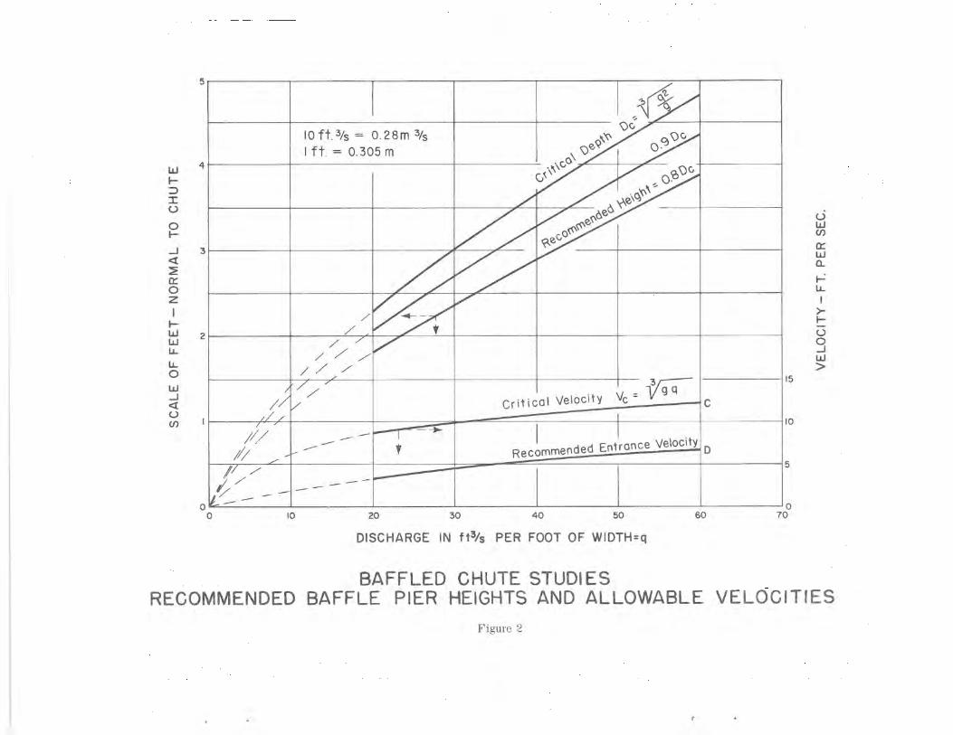
used design standards were established 0) A minimum of design limitations ri
was placed on this type of structure. These were a maximum unit
discharge of 60 (ft 3/s)/ft width (5.6 (m3/s)/m), and an approach
velocity of less than the critical velocity of the design flow based
on the design discharge. These criteria related to block or pier
height are presented in graphical form Figure 2. The other details
such as block width and spacing are standardized as a function of the
block height.
Many prototype operating experiences have been reported, all of them
generally favorable. The adverse comments such as excessive splash
and channel bank erosion at the water surface were easily corrected
by minor modifications such as the use of rip-rap. Some of the
reports on prototype operation indicated that the structures operated
at as much as twice the design discharge for short periods without
adverse effect. Because of this favorable operation, it was questioned
S
2
whether this concept could be used for a spillway design where
foundation conditions might not be favorable for a flip bucket or
conventional hydraulic jump energy dissipator and a moderate unit
discharge in the vicinity of 100 (ft 3/s)/ft width (9.3 (m3/s)/m width)
could be expected.
DEVELOPMENT TESTS
The first spillway design to use the concept of a baffled apron was
for a spillway rehabilitation project in Oregon. The Conconully
spillway was designed for a unit discharge of 78 (ft 3/s)/ft (7.2 (m3/s)/m),
a width of 150 ft (45.7 m), and a fall of 65 ft (19.8 m). The dimensions
of the structure were based on the same criteria as used for canal
structures by extrapolating the design curves. The structure was
studied with a sectional hydraulic model and subsequently constructed,
Figure 3.(2)
The Conconully spillway has operated at small discharges every year
since its completion. It was at this structure that a side benefit
of a baffled apron was discovered which had to do with nitrogen
supersaturation in the river downstream from the dam. Measurements
indicated that the flow from a slide gate controlled outlet works
adjacent to the spillway had an excess of dissolved nitrogen gas
greater than permitted by the Oregon Department of Fish and Game,
while flow at the base of the baffled spillway was well below
allowable limits and after the two flows merged the gas supersaturation
was well within permissible standards.
3
The Bonneville Hydraulic Laboratory of the Corps of Engineers
subsequently performed extensive model investigations to develop
spillway baffle blocks specifically shaped to provide the turbulence
necessary to reduce nitrogen supersaturation.
A second Bureau of Reclamation spillway using the baffled apron
concept was for the Marble Bluff Diversion Dam in Nevada. This
structure has a unit discharge of 113 (ft 3/s)/ft (10.5 (m3/s)/m)
with a 150 ft (45.7 m) width and a 70 ft (21.3 m) fall, Figure 4.
Hydraulic model studies were also made of this structure prior to
construction.
HYDRAULIC MODEL INVESTIGATIONS
Because of the apparent need for this type of structure, a hydraulic
testing program was initiated to generalize the design criteria for
large unit discharges. The test facility consisted of a large tank
or head box to contain the approach flow, a sloping apron that could
be adjusted for width, and an erodible sand bed in a tail box. The
baffle blocks were constructed of wood except for one row which
consisted of metal blocks equipped with piezometers so that impact
pressures could be recorded on the upstream face and, if present,
the extent of subatmospheric pressures in critical areas.
A model scale of 1:33 was selected to take full advantage of the
laboratory water supply capacity. The design unit discharge was
4
300 (ft 3/s)/ft (27.8 (m3/s)/m). The intial configuration was
obtained by extrapolating the criteria used for canal structures.
A 2:1 slope was used for all tests. It had been suggested that a
steeper slope was not practical for field construction and if the
steeper slope was necessary for a specific design, the suitability of
the structure could be confirmed by hydraulic model studies. Previous
experience had shown that a baffled apron installed on a slope flatter
than 2:1 performed as good or better than the standard design.
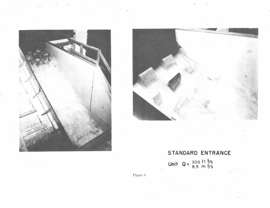
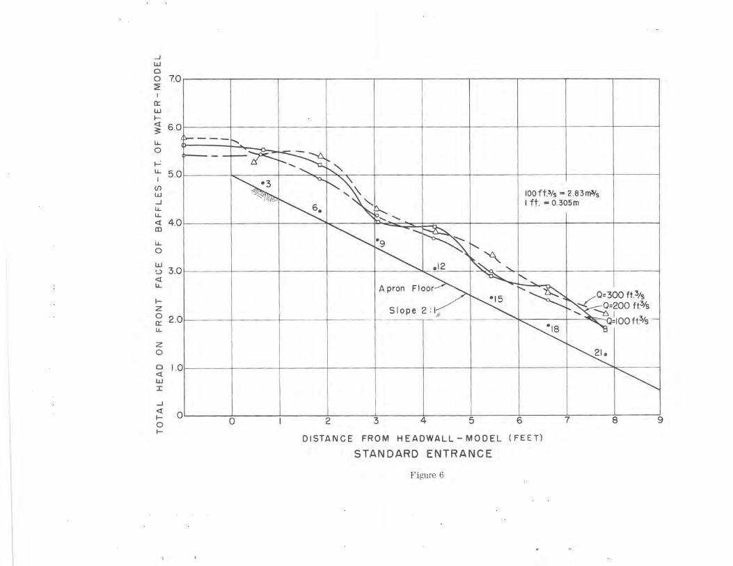
Tests with the basic design indicated that flow conditions were
essentially the same as had been found with smaller unit discharges,
Figure 5. Typically, there was no increase in the impact pressures
after the third row of baffles, Figure 6; discharges near the design
flow produced _less splash and spray and an apparently smoother water
surface than the smaller flows. Erosion at the base of the structure
was moderate for all tests. No subatmospheric pressures were measured
in the side and top piezometer. Actually, they were near atmospheric
for all flows, indicating full aeration. Some test runs were made
with discharges greater than design and in all cases the flow
appearance was improved, mainly less splash and spray, although
bottom erosion was moderately greater.
Many tests were made with the standard blocks used at different
block and row spacing. The results were usually poorer flow
conditions on the chute such as excessive splash or an increase in
velocity down the chute. Also tried were undersize baffles, oversize
5
baffles, and several combinations of sizes. Only rectangular shaped
baffles were used in these tests. It seemed conclusive that this
was a near optimum design with the only restriction being structural
considerations or what could be built as far as size and stability
are concerned.
One feature of the design that seemed to lend itself to some improve-
ment was the entrance. The row of blocks near the top of the structure
caused a significant increase in the water surface elevation, Figure 7.
This row could also become clogged with large debris causing the
upstream water level to encroach on the freeboard. The next phase
of the investigation was directed toward obtaining alternate entrance
configurations.
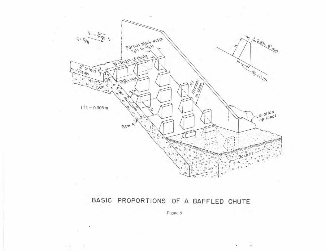
Three types of entrances were developed after many tests. The first
is the standard entrance, Figure 8, which gives the best flow conditions
at the upstream end of the chute and is recommended if an increase in
upstream water level is not objectionable.
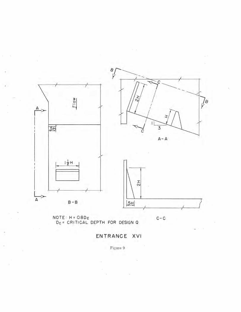
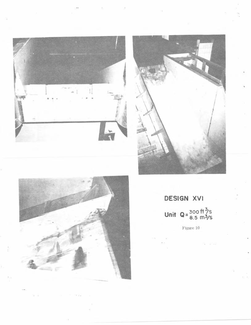
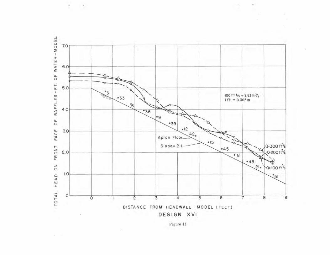
The second entrance, called entrance XVI, eliminates the top row of
blocks but substitutes a sloping or triangular block adjacent to
each sidewall, Figure 9. A larger fin of water forms on the sidewall
near the second row of blocks but does not overtop the sidewall if
the design height is used, Figure 10, This entrance does not cause
excessive acceleration before impinging on the first row of blocks,
Figure 11.
2
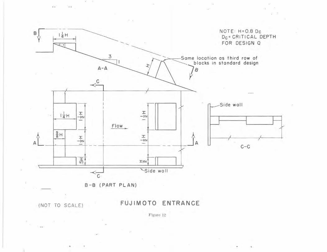
The third entrance is called the Fujimoto entrance and consists of
a serrated horizontal broad crested weir, Figure 12. The weir is
at the top of the chute in place of the first row of blocks. The
second row of blocks used with the standard entrance and the XVI
entrance are omitted. The configuration of the short and long sections
is important, a long section even thought it is not full width should
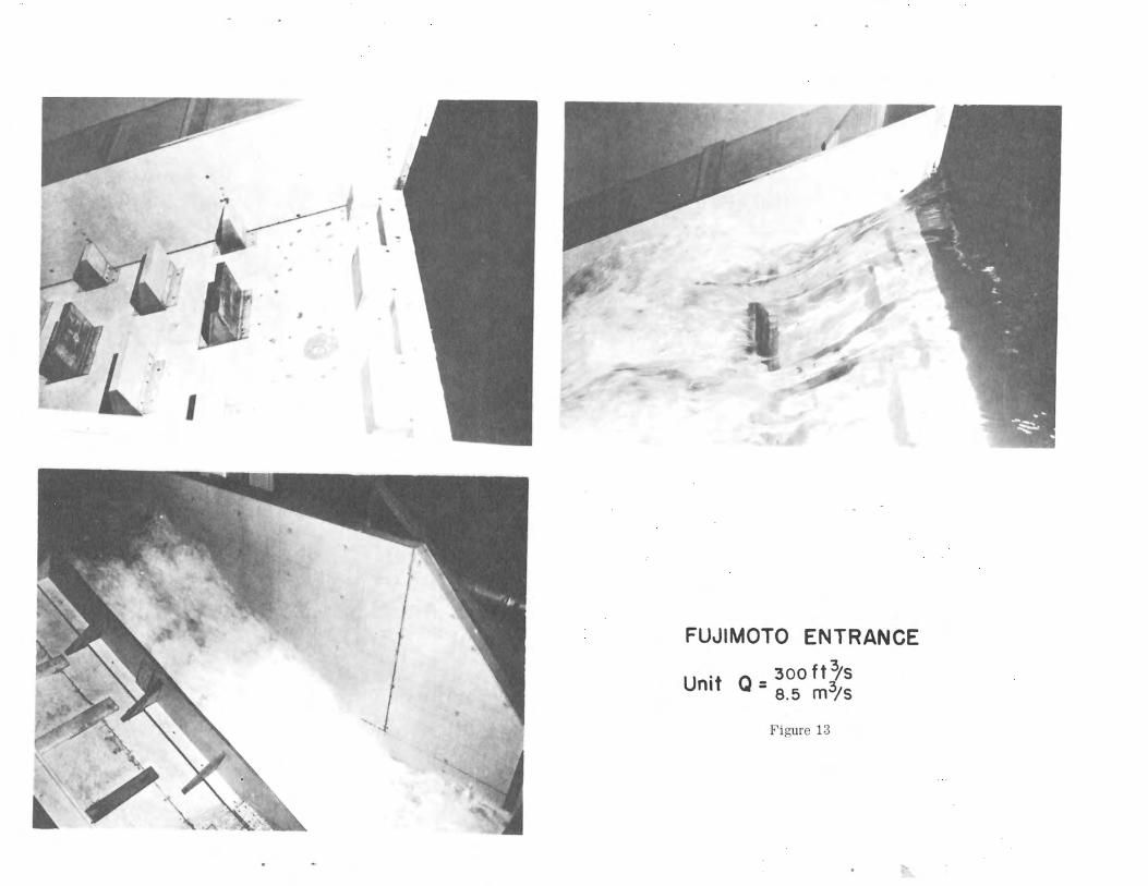
be placed next to the sidewalls. This entrance provides an acceptable
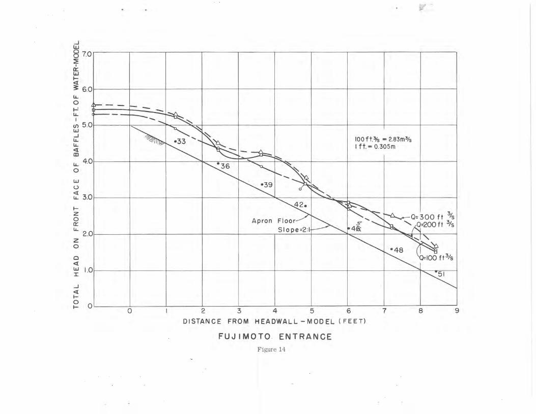
flow condition at the top of the chute, Figure 13, and fully retarded
acceleration by the third row of blocks, Figure 14.
Neither entrance XVI nor the Fujimoto entrance increases the elvation
of the approaching flow. It should be emphasized that the design
criteria requiring the velocity of the flow approaching the drop to
be less than critical velocity should be followed regardless of the
entrance configuration selected.
DESIGN EXAMPLE
As an illustration of the use of a baffled apron spillway consider
the design used for a comparatively small watershed with an intense
runoff. The watershed is approximately 63 mil (163 km2) with the
upper end heavily developed and criss-crossed with numerous roads.
The design operating criteria require that a detention reservoir be
able to hold the 100-year flood at the crest of the emergency spillway
and to pass the freeboard hydrograph (FBH) flood at the crest of the dam.
7
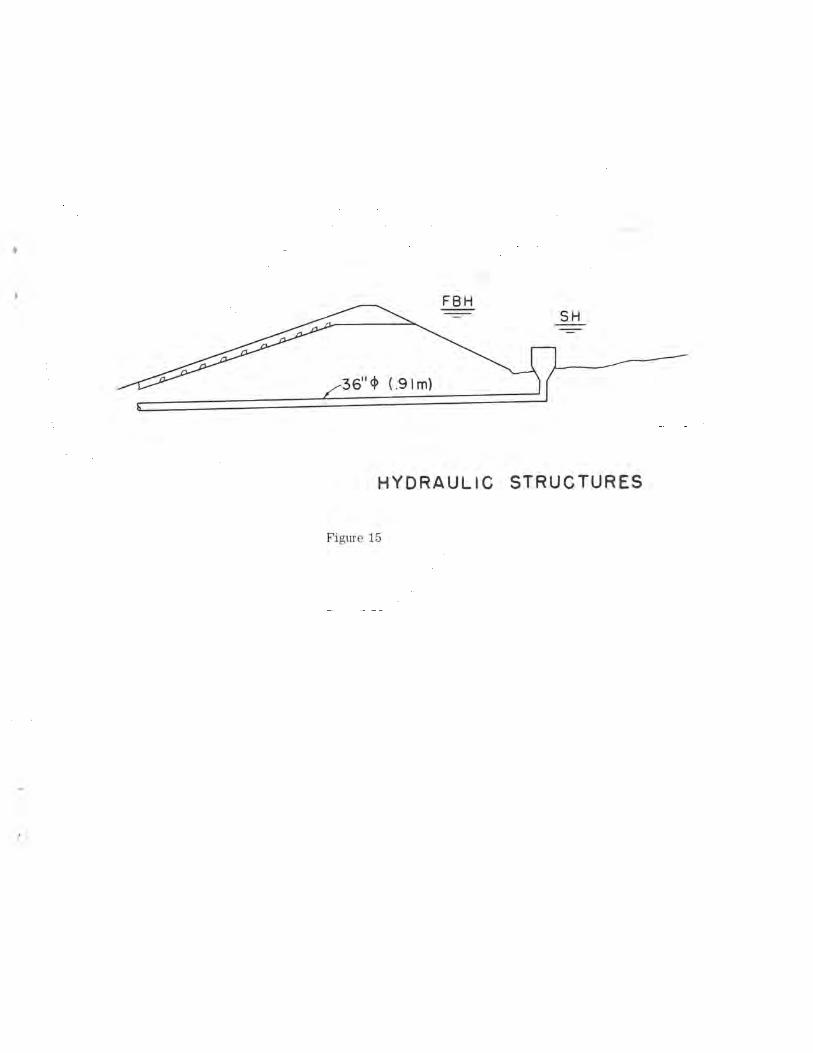
For this project, a vertical drop inlet is the service spillway
and a baffled apron spillway is planned for emergency use or the
FBH spillway, Figure 15.
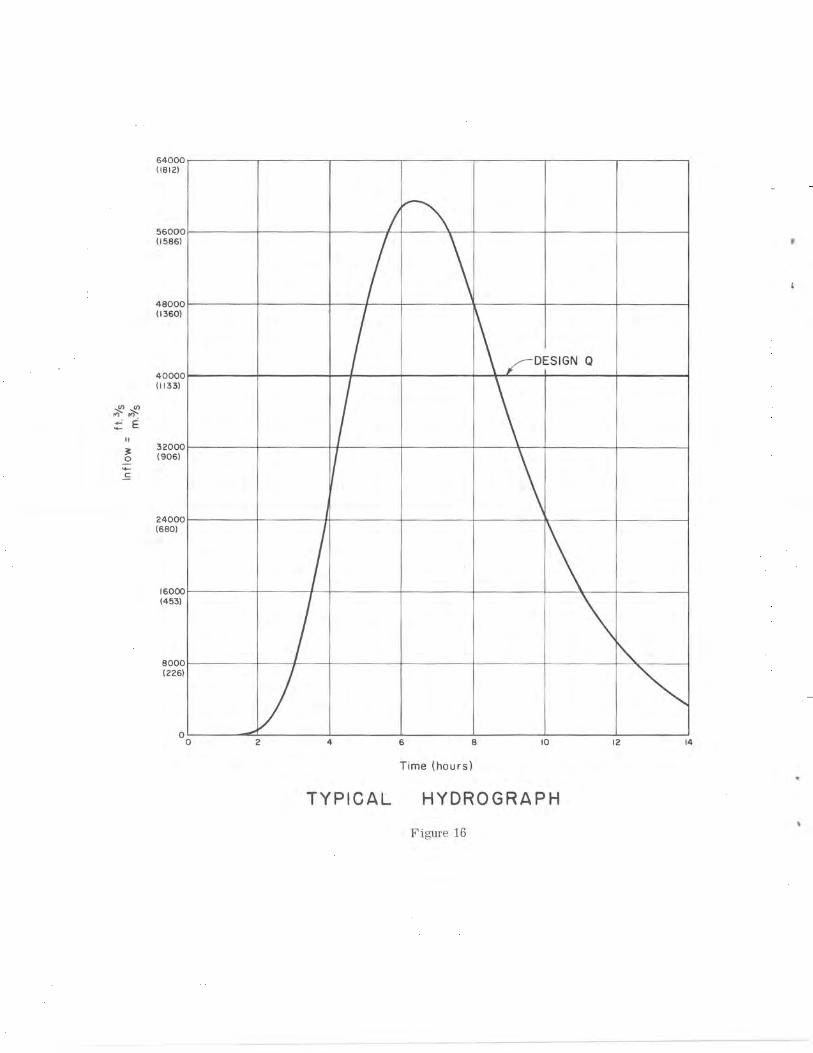
The freeboard hydrograph shows a maximum inflow of 60,000 ft3/s
(1700 m3/s), Figure 16. Arbitrarily, a design discharge of 40,000 ft3/s
(1133 m3/s) plus a surcharge of 20,000 ft3/s (567 m3/s) and a unit
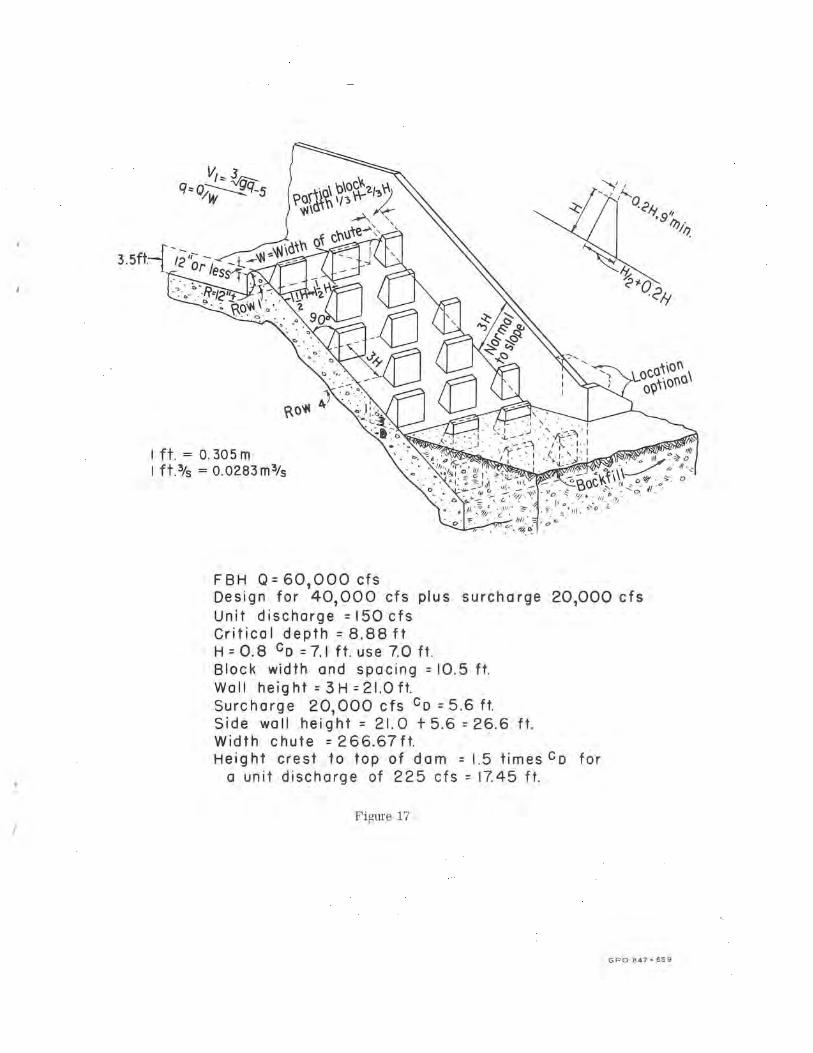
discharge based on the design discharge of 150 ft3/s/ft (13.9 m3/s/m).
This unit discharge has a critical depth of 8.88 ft (2.71 m) or a
block height of 7.0 ft (2.13 m), Figure 17. Using the design criteria,
the block width and spacing- will be 10.5 ft (3.20 m). The sidewall
height on the chute is 21.0 ft (6.40 m) plus 5,6 ft (1.71 m) for the
critical depth of the surcharge flow or a total of 26.6 ft (8.11 m).
The width of the chute will be 267 ft (81.4 m). The height from the
crest of the chute to the top of the dam is one and one-half times
the critical depth of the FBH flow or 17.45 ft (5,32 m). If a
standard entrance is used, the 17.45 ft (5.32 m) dimension will have
to be increased by 8 percent or to 18.85 ft (5.75 m). If a type XVI
or Fujimoto entrance is used, no additional height need to be provided.
CONCLUSIONS
1. Extended experience with baffled apron chutes has proved their
reliability and efficiency.
W
2. Model tests of specific projects showed that the concept could
be used in lieu of spillway energy dissipators at larger unit
discharges.
3. Further model studies were made to generalize the design criteria
for unit discharges up to 300 (ft 3/s)/ft (27.9 (m3/s)/m).
4. These studies indicated that this type of structure was satisfactory
for any discharge but structural and size-of-block limitations might
control the quantity of the design unit discharge.
5. Three alternative entrances were developed, two of which will not
increase the elevation of the approaching flow.
6. As with all new concepts, a design based on this example should
be confirmed by hydraulic model studies.
9
APPENDIX 1
(1) Peterka, A. J., "Hydraulic Design of Stilling Basins and Energy
Dissipators," Engineering Monograph No. 25, U. S. Department of
Interior, Bureau of Reclamation, 1964, pp. 154-188
(2) Rhone, T. J., "Studies to Determine the Feasibility of a Baffled
Apron Drop as a Spillway Energy Dissipator - Conconully Dam
Spillway - Okanogan Project, Washington," U. S. Bureau of
Reclamation, Report REC-ERC-71-29, 1972
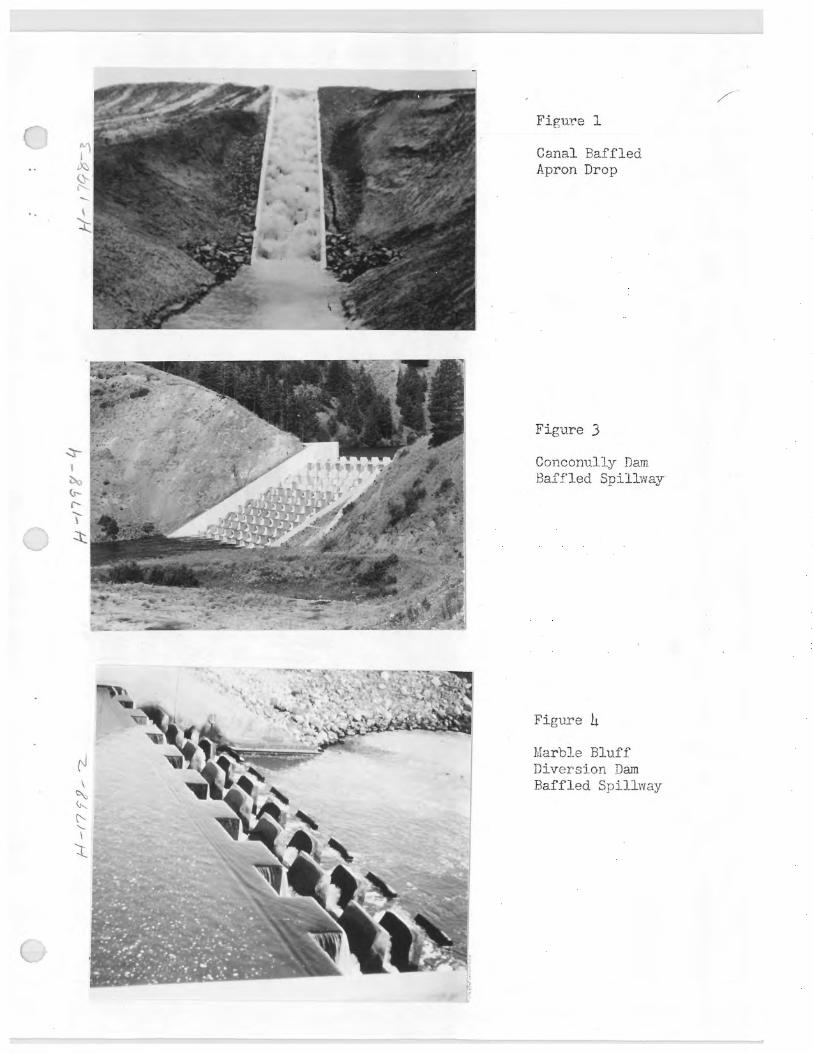
Figure i
Canal Baffled Apron Drop
Figure 3
Conconully Dam Baffled Spillway
I
U..
Z
Figure 4
Marble Bluff Diversion Dam Baffled Spillway
r+
'4 AV
(3 w U) Lr W a
L-i
U O J W
15
10
5
W 4
D
U
O E-
J 3 d
O z I H Ld 2 LLJ U- U- O LtJ J d U U)
0 0
s
3
yr QG
~Q G I 0 f t. 3/s = 0.28M 3/s I ft. = 0.305 m
®e QeQ
Gt~~\c apc
0~
rasa ire
R
/ Z /
3 g /
/ Critical Velocity = Vc C
Recommended Entrance Velocity D
10 20 30 40 50 60
DISCHARGE IN ft3/s PER FOOT OF WIDTH=q
0 70
BAFFLED CHUTE STUDIES RECOMMENDED BAFFLE PIER HEIGHTS AND ALLOWABLE VELOCITIES
Figure 2
.. ......
0
STANDARD ENTRANCE
Unit Q = 300 f t 3/S 8.5 m 3/S
Figure 5
•3 100 f t 3/5 = 2.8 3 MA/s
6. 1 ft. = 0.305 m
.12
Apron Floor •15 ~ 0=300 ft.3/s
Slope 2 1 ^ ~~=200 0/s
0I100f0/s
21.
0 I 2 3 4 5 6 7 8 9
J w 0 O 7.0 2
w
3 6.0
U- 0
5.0
w J w w a 4.0 m
U- 0 Ui
3.0 a U-
1--z r 2.0 U-
J Q C H 0
DISTANCE FROM HEADWALL—MODEL ( FEET)
STANDARD ENTRANCE
Figure 6

30
Z 25
W20 cn a
15 U
z 10 Lj- 0 5
0 0
0 20 40 60 80 100 % OF DESIGN 0
At Crest 1.01 Below Crest (.305m)
I.8' Below Crest (.55m)
EFFECT OF BLOCK LOCATION
ON RESERVOIR LEVEL
Figure 7
q ; ojw w~ 0213 \
~atih - r
less-- 2 x
0
I ft. = 0.305m
L oPtjOrlol
.~,1r_;i
o~.~o -e.\ , . ~ . ~ ,, /lye • ..
~.o/"i IAA-
~, .\t~~~~q `~/~~~ III .I
o nr .
BASIC PROPORTIONS OF A BAFFLED CHUTE
Figure 8
r
L--~'- A B - B
HWY
NOTE H = 0.8Dc C-C Dc = CRITICAL DEPTH FOR DESIGN 0
ENTRANCE XVI
Figure 9
DESIGN XVI
Unit Q = 300 ft 3/S S 8.5 m /S
Figure 10
DISTANCE FROM HEADWALL -MODEL ( FEET)
DESIGN XVI
Figure 11
3i • 3 3 \ 100 f t.3/S = 2.83 m 3/S I f t. = 0.305 m
'36 '9 ~ •39
.12
Apron Floor 42•
•15 Os Slope= 2:1 45 Q=300
Q=200 ft.% • 18
•48 21 •
b Q=100 ft ~s
51
0 1 2 3 4 5 6 7 8 y
J W 0 7.0
u- 5.0
w J U_ c 4.0 m
0
Ui 3.0 a
0 2.0 Ir U_
z 0 o I.0 a w
J Q C
0
NOTE: H=0.8 Dc Dc= CRITICAL DEPTH FOR DESIGN Q
location as third row of locks in standard design
a V—U
BI I'H Y ~-- 0
~C
B—B (PART PLAN)
(NOT TO SCALE) FUJ IM OTO ENTRANCE
Figure 12
~
FUJIMOTO ENTRANCE
Unit Q=300fl~5 8.5 / S
Figure 13
11
w
a 3 6.0 U_ O
U_
cn 5.0 w J U_ U_ a m U_ 4.0
w v LL 3.0
z O w U_
2.0 z O
- 33 10 Of t.3/s = 2.83 m 3/s I ft.= 0.305m
X36 ~
X39
42.
Apron Floor S, ~ 0=300
Q=200 ft 3/s ft /s
Slope =2:1 4i~C
b X48
I
Q=100 f t 3/s
51
0 1 2 3 4 5 6 7 8 9
DISTANCE FROM HEADWALL —MODEL ( FEET)
FUJ I MOTO ENTRANCE
Figure 14
FBH
36"~ (.91m)
HYDRAULIC STRUCTURES
Figure 15
64000 (1812)
56000 (1586)
48000 (1360)
IGN Q 40000 (1133)
MN MN w E
u 3 32000 0 (906)
c
24000 (680)
16000 (453)
8000 ( 226)
a 2 4 6 8 10 12 14
Time (hours)
TYPICAL HYDROGRAPH
Figure 16
L
RIM
9
9" `N..
K
wi
n
V,3 q- p,W ,9 5 po`t o\
w~d~r ~ ✓~-
F-- , w ,w ~d~h of ohute
3.5ft,-- 2 Or /ess - ' -
ono\
ft. = 0.305m o' I ft.3/S = 0.0283 m3/s ,
FBH Q= 601000 cfs Design for 40,000 cfs plus surcharge 20,000 cfs Unit discharge = 150 cfs Critical depth = 8.88 ft H = 0.8 CD =7.1 ft. use 7.0 ft. Block width and spacing = 10.5 ft. Wall height = 3H = 21.0 ft. Surcharge 20,000 cfs CD = 5.6 ft. Side wall height = 21.0 +5.6 =26.6 ft. Width chute = 266.67ft. Height crest to top of dam = 1.5 times CD for
a unit discharge of 225 cfs = 17.45 ft.
Figure 17
GPO 847-659

t
I
N


i
•3
_-~__ - - _ _ _ _ _ _ _ _
- - 3' - _
'~ v. ~ ~.
,~
8
,r
t
L
I,~
}