Embed Size (px)
Citation preview


--

A Policy all Design Standards Interstate System
AMERICAN ASSOCIATION OF STATE HIGHWAY AND TRANSPORTATION OFFICIALS
VOTING MEMBERS
Officers:
EXECUTIVE COMMITIEE 2004-2005
President: Jack Lettiere, New Jersey
Vice President: Open Position
Secretary-Treasurer: Larry M. King, Pennsylvania
Regional Representatives:
REGION I: Allen Biehler, Pennsylvania, One-Year Term
Dan Tangherlini, District of Columbia, Two-Year Term
REGION II: Gabriel Alcaraz, Puerto Rico, One-Year Term
Harold Linnenkohl, Georgia, Two- Year Term
REGION III: Gloria Jeff, Michigan, One-Year Term
Frank Busalacchi, Wisconsin, Two-Year Term
REGION IV: Tom Norton, Colorado, One-Year Term
David Sprynczynatyk, North Dakota, Two-Year Term
NONVOTING MEMBERS
Immediate Past President: John R. Njord, Utah
AASHTO Executive Director: John Horsley, Washington, DC
-

~--------------------------------------------------------------------------------~=============--=-,.
A Po/i(,y Ofl D()sign Standards Interstate Syslem
TECHNICAL COMMITTEE ON GEOMETRIC DESIGN 2004
Members
Robert L. Walters, Arkansas. Chair
William A. Prosser, Federal Highway Administration. Secretary
Jim McDonnell, AASHTO Liaison
Reza Amini, Oklahoma
Don T. Arkle, Alabama
Paul Bereich, \1Yoming
Kenneth T. Briggs, Marylalld
James O. Brewer, Kansas
Philip 1. Clark, New York
David Hutchison, National League of Cities
Jeff C. Jones, Tennessee
Wayne Kinder, Nevada
John LaPlante, American Public Works Association
Donald A. Lyford, New Hampshire
Reza Maleki, Port A whori t)' ol
New York and New Jersey
Mark A. Marek, Texas
John Pickering, Mississippi
James Rosenow, Minnesota
Norman H. Roush, West Virginia
Joe Ruffer, National Association of County Engineers
Larry Sutherland, Ohio
Karla Sutliff, Calilornia
Max Valerio, New Mexico
Ted Watson, Nebraska
iii
-A Policy on Design Standards IllIerstate Srstelll
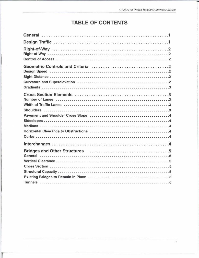
TABLE OF CONTENTS
General ...................................................... 1
Design Traffic ................................................. 1
Right-of-Way .................................................. 2 Right-of-Way ............................................................. 2
Control of Access ................. . ....................................... 2
Geometric Controls and Criteria ................................. 2 Design Speed ............................................................ 2
Sight Distance ............................................................ 2
Curvature and Superelevation .............................................. 2
Gradients ................................................................ 3
Cross Section Elements ........................................ 3 Number of Lanes ......................................................... 3
Width of Traffic Lanes ................... .. ... ... .... ... ................... 3
Shoulders ............................. . ................................. 3
Pavement and Shoulder Cross Slope ........................................ 4
Sides lopes ......................... . ..................................... 4
Medians ..................................................... .. .......... 4
Horizontal Clearance to Obstructions ........................................ 4
Curbs .................................. . . . .............................. 4
Interchanges .................................................. 4
Bridges and Other Structures ................................... 5 General ................................................................. 5
Vertical Clearance ................................. .. ......... ... . .. ....... 5
Cross Section ............................................................ 5
Structural Capacity ............................ . ........................... 5
Existing Bridges to Remain in Place ......................... . ............... 5
Tunnels ................................................................. 6
v
A Polin Oil Desigll Stalldards Iltlerstate Srstelll
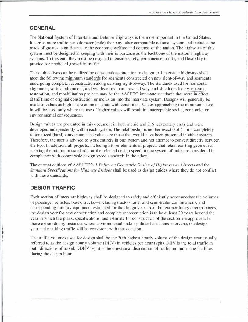
GENERAL
The National System of Interstate and Defense Highways is the most important in the United States. It carries more traffic per kilometer (mile) than any other comparable national system and includes the roads of greatest significance to the economic welfare and defense of the nation . The highways of this system must be designed in keeping with their importance as the backbone of the nation's highway systems. To this end, they must be designed to ensure safety, permanence, utility, and flexibility to provide for predicted growth in traffic.
These objectives can be realized by conscientious attention to design. All interstate highways shall meet the following minimum standards for segments constructed on !lew right-of-way and segments undergoing complete reconstructio;;)ong existing right-of-way. The standards used for horizontal alignment, verti"caf alig-;;m~aildwidths of median, traveled way, and shoulders for resurfacing .. restoration, and rehabilitation projects may be the AASHTO interstate standards that were in effect at the-ti-me of original construction or inclusion into the interstate system. Designs will generally be made to values as high as are commensurate with conditions. Values approaching the minimums here in will be used only where the use of higher values will result in unacceptable social, economic, or environmental consequences.
Design values are presented in this document in both metric and U.S. customary units and were developed independently within each system. The relationship is neither exact (soft) nor a completely rationalized (hard) conversion. The values are those that would have been presented in either system. Therefore, the user is advised to work entirely in one system and not attempt to convert directly between the two. In addition, all projects, including 3R, or elements of projects that retain existing geometrics meeting the minimum standards for the selected design speed in one system of units are considered in compliance with comparable design speed standards in the other.
The current editions of AASHTO's A Policy on Geometric Design of Highways and Streets and the Standard Specifications for Highway Bridges shall be used as design guides where they do not conflict with these standards.
DESIGN TRAFFIC
Each section of interstate highway shall be designed to safely and efficiently accommodate the volumes of passenger vehicles, buses, trucks- including tractor-trailer and semi-trailer combinations, and corresponding military equipment estimated for the design year. In all but extraordinary circumstances, the design year for new construction and complete reconstruction is to be at least 20 years beyond the year in which the plans, specifications, and estimate for construction of the section are approved. In those extraordinary instances where environmental and/or political decisions intervene, the design year and resulting traffic will be consistent with that decision.
The traffic volumes used for design shall be the 30th highest hourly volume of the design year, usually referred to as the design hourly volume (DHV) in vehicles per hour (vph). DHV is the total traffic in both directions of travel. DDHV (vph) is the directional distribution of traffic on multi-lane facilities during the design hour.

A PoNey 011 Design Standards 11l1l~rsl£lle System
RIGHT-OF-WAY
Right-of-Way
The width of right-of-way shall be sufficient to accommodate the roadway cross section elements and requisite appurtenances necessary for an adequate facility in the design year and for known future improvements.
Control of Access
Access to the interstate system shall be fully controlled. The interstate highway shall be grade separated at all railroad crossings and selected public crossroads. At-grade intersections shall not be allowed. To accomplish this, the intersecting roads are to be grade separated, terminated, rerouted, and/or intercepted by frontage roads. Access is to be achieved by interchanges at selected public roads.
Access control shall extend the full length of ramps and terminals on the crossroad. Such control
shall either be acquired outright prior to construction or by the construction of frontage roads or by a combination of both.
Access control beyond the ramp terminals should be affected by purchasing access rights, providing frontage roads, controlling added comer right-of-way areas, or prohibiting driveways. Such control shou ld extend beyond the ramp terminal at least 30 m ( 100 ft) in urban areas and 90 m (300 ft) in rural areas. However, in areas of high traffic volume, where exists the potential for development which would create operational or safety problems, longer lengths of access control should be provided.
GEOM ETRIC CONTROLS AND CRITERIA
Design Speed A minimum design speed of 110 kmlh (70 mph) should be used for rural areas. Where terrain is mountainous, a design speed from 80 to 100 kmlh (50 to 60 mph) may be used. In urban areas, the design speed shall be at least 80 kmlh (50 mph).
Sight Distance
The minimum stopping sight distance shall be the values establi shed in the current edition of AASHTO's A Policy on Geometric Design (~l Highways lind Streets for the appropriate design speed.
Curvature and Superelevation
Curvature, superelevation, and allied features, such as transition curves, shall be correlated with the design speed in accordance with the current edition of AASHTO's A Policy Oil Geometric Design of Highways and Streets.
-

A Po/icy on Design Standarc/.\' Imerstate System
Gradients Maximum grades as a function of the design speed and the type of terrain are shown in the following table:
Metric U.S. Customary
Design Speed (km/h) Design Speed (mph)
80 90 100 110 120 130 50 55 60 65 70 75 80
Type of Terrain Grades (%)* Grades (%)*
Level 4 4 3 3 3 3 4 4 3 3 3 3
Rolling 5 5 4 4 4 4 5 5 4 4 4 4
Mountainous 6 6 6 5 - - 6 6 6 5 5 -
• Grades up to one percent steeper than the value shown may be provided in urban areas with crucial right-of-way constraints or where needed in mountainous terrain.
CROSS SECTION ELEMENTS
Number of Lanes
3
4
-
A minimum of four traffic lanes shall be provided on the interstate system. The number of lanes shall be sufficient to accommodate the DHV at an acceptable level of service for the applicable conditions. A capacity analysis using the design year traffic should be performed to determine the number of lanes required to achieve the acceptable level of service. Refer to AASHTO's A Policv on Geometric Design o.lHighways and Streets for guidance in the selection of level of service.
On ascending grades, which exceed the critical design length, a climbing lane analysis should be performed and climbing lanes added where appropriate. Likewise, on extended lengths of maximum or near maximum descending grades, emergency escape ramps should be added where an analysis indicates they are required.
Width of Traffic Lanes All traffic lanes shall be at least 3.6 m (12 ft) wide.
Shoulders
The paved width of the right shoulder shall not be less than 3.0 m (10 ft). Where truck traffic exceeds 250 DDHV, a paved shoulder width of 3.6 m (12 ft) should be considered. On a four-lane section, the paved width of the left shoulder shall be at least 1.2 m (4.J!1. On sections with six or more lanes, a 3.0 m (10 ft) paved width for the left shoulder should be provided. Where truck traffic exceeds 250 DDHV, a paved width of 3.6 m (12 ft) should be considered.
In mountainous terrain, a reduced paved shoulder width together with a minimal median width may be used to reduce the high costs associated with providing a full width roadway cross section. In these instances, a 2.4 m (8 ft) minimum paved right shoulder and a 1.2 m (4 ft) minimum paved left shoulder may be used on a traveled way consisting of four or six lanes. Where eight or more lanes are provided, a 2.4 m (8 ft) minimum paved shoulder width should be used on both sides.

A Poliev 011 Design Standards Interstate System
Pavement and Shoulder Cross Slope On tangent sections, the pavement cross slope shall be a minimum of 1.5 percent and desirably two percent. In areas of intense rainfall, the cross slope may be increased to 2.5 percent. Paved shoulders should have a cross slope in the range of two to six percent but not less than the cross slope of the adjacent pavement.
Sideslopes Foreslopes within the clear zone should not be steeper than I Y:4H and desirably should be I Y:6H or flatter. Where steeper slopes are used within the clear zone, roadside barriers shall be installed where warranted by the criteria in the current edition of AASHTO's Roadside Design Guide.
Medians
Medians in rural areas in level or rolling topography shall be at least II m (36 ft) wide. Medians in urban or mountainous areas shall be at least 3.0 m (10 ft) wide. AASHTO's Roadside Design Guide should be consulted to determine the details and warrants, based on consideration of average daily traffic, median width, and crash history, for barrier installation in the median. When economically feasible, consideration should be given to decking over the opening between parallel structures and extending a median barrier across the deck. Where continuous decking is not feasible, median barriers or guardrails should be installed to stop or redirect an errant vehicle safely.
Horizontal Clearance to Obstructions
The width of the clear recovery area shall be commensurate with the design speed and roadside conditions, and be determined through application of the currently accepted procedures in the AASHTO Roadside Design Gllide. To the extent practicable, the piers and abutments of overcrossing structures should be designed to provide a horizontal clearance equal to the clear recovery area.
In restricted areas, it may be necessary to construct barriers, walls, piers, abutments or other unyielding objects nearer to the traveled way than the width required for a clear recovery area. Fixed objects within the limits of the clear recovery area shall be made breakaway, made yielding, or be shielded by installation of crashworthy barriers or attenuators. The minimum horizontal clearance from the edge of the traveled way to the face of the barrier shall be consistent with the requirements for the paved shoulder width.
Curbs . YeItical curbs shall not be used. Sloping curbs, when used, should be located at the outer edge of the paved shoulder. The height of sloping curb should be limited to 100 mm (4 in).
The use of curbs in conjunction with guardrail is discouraged. When the installation of curb is necessary in conjunction with a guardrail, the face of the curb should be located behind the face of the guardrail, or at least no closer to the traveled way than the face of the guardrail. AASHTO's Roadside Design Gllide should be consulted for detailed information concerning installation of curb in conjunction with guardrail.
INTERCHANGES
Interchanges shall be provided between all intersecting interstate routes, between other selected access-controlled highways, and at other selected public highways to facilitate the distribution of traffic. Each interchange shall provide for all traffic movements.
4

A Policy 011 Design StGlu/ards Interstale Syslem
The ramp curvature, pavement widths, and related elements, which constitute an interchange, shall be adequate to accommodate the appropriate design vehicles.
Spacing of interchanges has a significant effect on the operation of interstate highways. In areas of concentrated development, proper spacing may be difficult to obtain because of demand for frequent access. As a rule, minimum spacing should be 1.5 km (I mil in urban areas and 5 km (3 mil in rural areas, based on crossroad to crossroad spacing. In urban areas, spacing of less than 1.5 km (I mil may be developed by grade-separated ramps or by collector-distributor roads.
BRIDGES AND OTHER STRUCTURES
General
The following standards apply to interstate highway bridges, overpasses and underpasses. Standards for crossroad overpasses and underpasses are to be those of the crossroad.
Vertical Clearance On all rural sections, the clear height of structures shall be not less than 4.9 m (16 ft) over the entire roadway width, including the width of paved shoulder. In urban areas, the 4 .9 m (16 ft) clearance shall apply at least to a single interstate routing. On other interstate urban routes, the clear height shall be not less than 4.3 m (14 ft). An allowance should be made for future resurfacing. The vertical clearance to sign trusses and pedestrian overpasses shall be 5.1 m (17 ft). On interstate urban routes with less than the 4.9 m (16 ft) clearance, the vertical clearance to sign trusses shall be 0.3 m (I ft) greater than the minimum clearance of other structures. The vertical clearance from the deck to the cross bracing on through truss structures shall also be a minimum of 5.1 m (17 ft).
Cross Section The width of all bridges, including grade separation structures, measured between rails, parapets, or barriers shall equal the full paved width of the approach roadways. The approach roadway includes the width of paved shoulders. Long bridges, defined as bridges having an overall length in excess of 60 m (200 ft) , may have a lesser width. Such bridges shall be analyzed individually. On long bridges, offsets toparapet. rail or barrier shall be at least 1.2 m (4 ft) measured from the edge of the nearest traffic lane on both the left and the right.
Structural Capacity
All new bridges shall have at least an MS 18 (HS 20) structural capacity. A bridge can remain in place if the operating rating capacity can safely service the system for an additional 20-year service life.
Existing Bridges to Remain in Place
Mainline bridges on the interstate system and bridges on routes to be incorporated into the system may remain in place if, as a minimum, they meet the following: a) the bridge cross section consists of 3.6 m (12 ft) lanes, 3.0 m (10ft) shoulder on the right and 1.1 m (3 .5 ft) shoulder on the left; b) for long bridges, the offset to the face of parapet or bridge rail on both the left and right is 1.1 m (3.5 ft) measured from the edge of the nearest traveled lane; c) bridge railing shall meet or be upgraded to current standards.
.')

A Policy Oil Desigll Standards Interstate Syslnll
Tunnels
From the standpoint of service to traffic , tunnels should not differ materially from grade separation structures. Essentially the same standards apply except the minimum values normally are used because of high cost and restricted right-of-way.
The vertical clearance for tunnels shall be at least 4.9 m (16 ft) except where an alternative routing providing the 4.9 m (16 ft) clearance is available. For those lesser situations, at least a 4.3 m (14 ft) clearance should be provided. An allowance for future resurfacing may be added to the minimum vertical clearance requirements.
The desirable cross section for tunnels is at least 13.1 m (44 ft). This width consists of two 3.6 m (12 ft)
lanes, a 3.0 m (10ft) right shoulder, a 1.5 m (5 ft) left shoulder, and a 0.7 m (2.5 ft) safety walk on each side. The roadway width may be distributed to either side in a different manner if needed to better fit the dimensions of the tunnel approach.
Because of the high cost associated with tunnels, a reduced width can be accepted. However, the total clearance between walls of a two-lane tunnel must be at least 9.0 m (30 ft). The minimum roadway width between curbs should be at least 0.6 m (2 ft) greater than the approach traveled way, but no less than 7.2 m (24 ft). The curb or sidewalk on either side should be a minimum of 0.5 m (1.5 ft). The roadway width and the curb or sidewalk width can be varied as needed within the 9.0 m (30 ft) minimum wall clearance; however each width should not be less than the minimum value stated above.
In lieu of a safety walk and offset to the curb on each side, a 1.0 m (3.0 ft) offset incorporating a safety shape at the wall can replace the safety shape and curb on one or both sides of the traveled way. A vertical wall may be used as an alternate for the safety shape.
6