Embed Size (px)
Citation preview

User’s Guide
Eastman Kodak Company343 State StreetRochester, NY 14650 U.S.A.© Kodak, 2010. All rights reserved. TM: Kodak, Truper
6J7207A
CYAN MAGENTA YELLOW BLACKCYAN
8.5 x 11” Folded
GUIDE COVER-KODAK SCANNERS
FONTS
Whitney K Family
SIZE P/N SWATCHES
FILE FORMAT
DESIGN/IMPLEMENTATION
DATE12.22.09
6J7207A
DE MEYER
4 COLOR PROCESS
ARTWORK NAME
PRINTING INFORMATION
0000-000ECO LANGUAGES
ILLUSTRATOR CS3
EN
A-616606J7207
Truper3210 Scanner3610 Scanner
¯
Safety
User Precautions• Place the scanner on a sturdy, level work surface capable of supporting at least 31.75 kg (70 lbs) and leave adequate
clearance on all sides of the scanner.
• When relocating the scanner, it is recommended that two people lift the scanner and use safe lifting techniques.
• Do not install the scanner in a location subject to dust, humidity or steam. This may cause electrical shock or a fire. Only use the scanner indoors in a dry location.
• Make sure the electrical power outlet is located within 1.52 meters (5 feet) of the scanner and is easily accessible.
• When disconnecting equipment from the electric socket, be sure to grasp the plug, not the cord.
• Be sure the power cord is securely plugged into the wall outlet. Failure to do so may cause electrical shock or fire.
• Do not damage, knot, cut or modify the power cord or use a damaged power cord. This may cause electrical shock or fire.
• The scanner requires a dedicated and properly grounded power outlet. Do not use an extension cord or power strip with the scanner.
• Do not leave the power cord plugged into the AC outlet if the scanner is not used for an extended period of time.
• Leave sufficient space around the power outlet so it can be easily unplugged in case of an emergency.
• Do not use the scanner if it becomes inordinately hot, has a strange odor, emits smoke, or makes unfamiliar noises. Immediately stop the scanner and disconnect the power cord from the power outlet. Contact Kodak Service.
• Do not disassemble, service or modify the scanner except as explained in the User’s Guide.
• When using the flatbed for unbound or single pages, keep the top lid closed while scanning.
• Do not move the scanner with the power cord and interface cable attached. This may cause damage to the cord/cable. Remove the power cord from the wall outlet before moving or relocating the scanner.
• Follow the Kodak recommended cleaning procedures. Do not use air, liquid or gas spray cleaners. These cleaners displace dust, dirt and debris to other locations within the scanner, which may cause the scanner to malfunction.
• Material Safety Data Sheets (MSDS) for chemical products are available on the Kodak website at: www.kodak.com/go/msds. When accessing the MSDSs from the website, you will be required to provide the catalog number or keyword of the consumable you want the Material Safety Data Sheet for. See the section entitled, “Supplies and consumables” later in this guide for supplies and catalog numbers.
Users and their employers need to observe the common sense precautions applicable to the operation of any machinery. These include, but are not limited to, the following:
• Do not wear loose clothing, unbuttoned sleeves, etc.
• Do not wear loose jewelry, bracelets, bulky rings, long necklaces, etc.
• Hair length should be kept short, using a hair net if needed, or tying long hair up in a bundle.
• Remove all other loose objects from the area that could be drawn into the machine.
• Take sufficient breaks to maintain mental alertness.
• Use only the recommended cleaning supplies.
• Do not use canned/compressed air.
Supervisors should review their employee practices and make compliance with these precautions a part of the job description for operation of the scanner or any mechanical device.
Environmental information• The Kodak Truper Scanners are designed to meet worldwide environmental requirements.
• Guidelines are available for the disposal of consumable items that are replaced during maintenance or service; follow local regulations or contact Kodak locally for more information.
• The product packaging is recyclable.
• Kodak Truper Scanners are Energy Star compliant and shipped from the factory with the default time set to 15 minutes.
European UnionThis symbol indicates that when the last user wishes to discard this product, it must be sent to appropriate facilities for recovery and recycling. Please contact your local Kodak representative or refer to www.kodak.com/go/recycle for additional information on the collection and recovery programs available for this product.
Please consult www.kodak.com/go/REACH for information about the presence of substances included on the candidate list according to article 59(1) of Regulation (EC) No. 1907/2006 (REACH).
Acoustic emissionMaschinenlärminformationsverordnung – 3, GSGVDer arbeitsplatzbezogene Emissionswert beträgt <70 dB(A).
[Machine Noise Information Ordinance — 3, GSGVThe operator-position noise emission value is <70 dB(A).]
EMC statementsUnited StatesThis equipment has been tested and found to comply with the limits for a Class A digital device pursuant to Part 15 of the FCC rules. These limits are designed to provide reasonable protection against harmful interference when the equipment is operated in a commercial environment. This equipment generates, uses, and can radiate radio frequently energy and, if not installed and used in accordance with the instruction manual, may cause harmful interference to radio communications. Operation of this equipment in a residential area is likely to cause harmful interference in which case the user will be required to correct the interference at their own expense.
JapanThis is a Class A product based on the standard of the Voluntary Control Council for interference by information Technology Equipment (VCCI). If this equipment is used in a domestic environment, radio disturbance may arise. When such trouble occurs, the user may be required to take corrective action.
TaiwanWARNING: This is a Class A product. In a domestic environment this product may cause radio interference in which case the user may be required to take adequate measures.
Peoples Republic of ChinaWARNING: This is a Class A product. In a domestic environment this product may cause radio interference in which case the user may be required to take adequate measures.
KoreaPlease note that this equipment has obtained EMC registration for commercial use. In the event that it has been mistakenly sold or purchased, please exchange it for equipment certified for home use.
European UnionWARNING: This is a Class A product. In a domestic environment this product may cause radio interference in which case the user may be required to take adequate measures.
OVERVIEW 1-1
INSTALLATION 2-1
USING THE SCANNER 3-1
ADVANCED FEATURES 4-1
USER UTILITY 5-1
MAINTENANCE 6-1
TROUBLESHOOTING 7-1
APPENDICIES A-E
A-61660 April 2010 1-1
1 Overview
Contents Optional accessories....................................................................... 1-2What’s in the box ........................................................................... 1-2Scanner components ...................................................................... 1-3
Front view: Trūper 3610 Scanner ............................................... 1-3Front view: Trūper 3210 Scanner ............................................... 1-4Rear view: Trūper 3610 Scanner................................................ 1-5Rear view: Trūper 3210 Scanner................................................ 1-6Inside view.................................................................................. 1-7
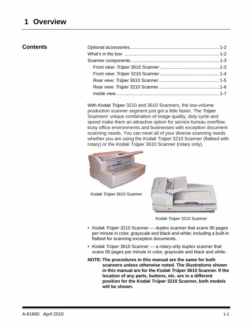
With Kodak Trūper 3210 and 3610 Scanners, the low-volume production scanner segment just got a little faster. The Trūper Scanners’ unique combination of image quality, duty cycle and speed make them an attractive option for service bureau overflow, busy office environments and businesses with exception document scanning needs. You can meet all of your diverse scanning needs whether you are using the Kodak Trūper 3210 Scanner (flatbed with rotary) or the Kodak Trūper 3610 Scanner (rotary only).
• Kodak Trūper 3210 Scanner — duplex scanner that scans 90 pages per minute in color, grayscale and black and white; including a built-in flatbed for scanning exception documents.
• Kodak Trūper 3610 Scanner — a rotary-only duplex scanner that scans 90 pages per minute in color, grayscale and black and white.
NOTE: The procedures in this manual are the same for both scanners unless otherwise noted. The illustrations shown in this manual are for the Kodak Trūper 3610 Scanner. If the location of any parts, buttons, etc. are in a different position for the Kodak Trūper 3210 Scanner, both models will be shown.
Kodak Trūper 3610 Scanner
Kodak Trūper 3210 Scanner
1-2 A-61660 April 2010
Optional accessories Long Document Paper Weight — designed to aid in scanning extremely long documents. The paper weight improves long document handling by applying a small and uniform amount of pressure, for long documents to run smoothly through the scanner transport. For use with both the Kodak Trūper 3210 or 3610 Scanner. CAT No. 109 2436
Imprinter — front page (pre-scan) imprinter prints the user-specified alphanumeric string on the front side of documents before they are scanned. CAT No. 896 1955
Memory Upgrade Kit — some scanning work may require additional memory depending on variables such as the size of the documents you are scanning and the desired image resolution. For example, two-sided scanning of larger document sizes such as A3, or color scanning at a resolution of 600 dpi may require additional memory. If you need additional memory, the Memory Upgrade Kit is available. CAT No. 132 6313
What’s in the box • Kodak Trūper 3210 or 3610 Scanner• Power cord• USB cable• Wire Frame (3610 Scanner only)• Shading Sheet• Starter Cleaning Kit• Kodak Trūper Quick Installation Guide• Installation Resource CD which includes the following:
- User Utility- ISIS/TWAIN Driver- VRS Software- Kodak Trūper User’s Guide (multiple languages)- VRS User Manual and Release Notes
A-61660 April 2010 1-3
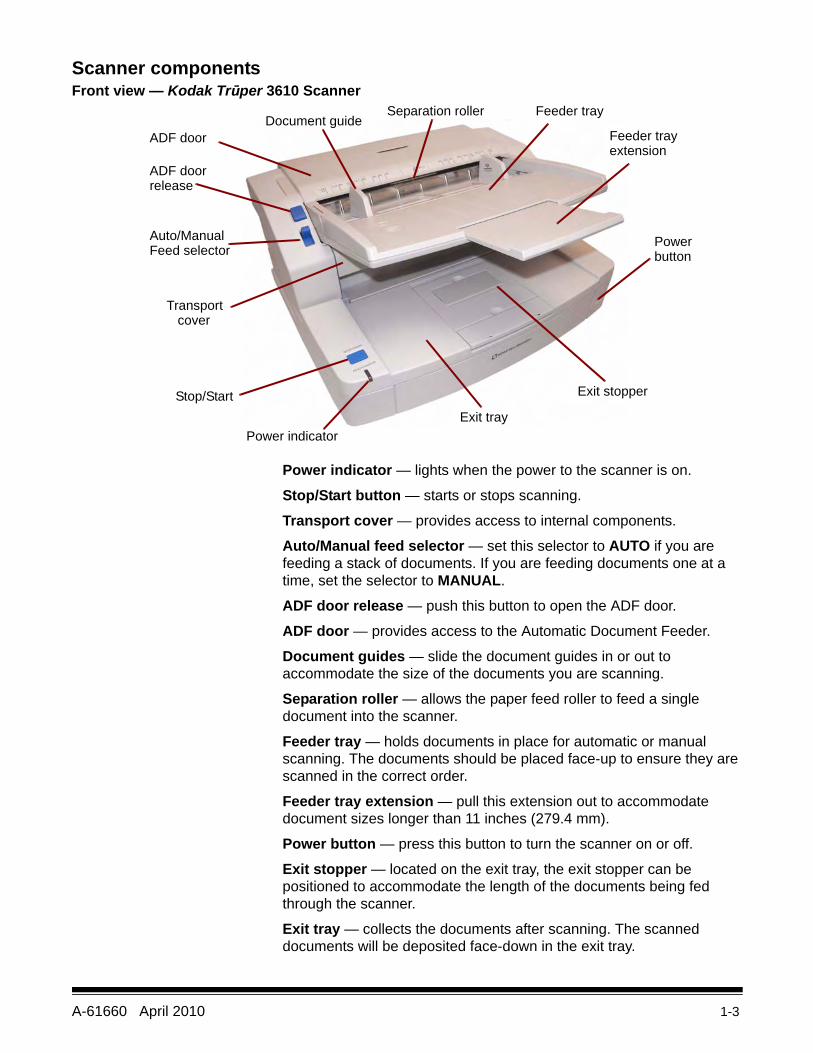
Scanner componentsFront view — Kodak Trūper 3610 Scanner
Power indicator — lights when the power to the scanner is on.
Stop/Start button — starts or stops scanning.
Transport cover — provides access to internal components.
Auto/Manual feed selector — set this selector to AUTO if you are feeding a stack of documents. If you are feeding documents one at a time, set the selector to MANUAL.
ADF door release — push this button to open the ADF door.
ADF door — provides access to the Automatic Document Feeder.
Document guides — slide the document guides in or out to accommodate the size of the documents you are scanning.
Separation roller — allows the paper feed roller to feed a single document into the scanner.
Feeder tray — holds documents in place for automatic or manual scanning. The documents should be placed face-up to ensure they are scanned in the correct order.
Feeder tray extension — pull this extension out to accommodate document sizes longer than 11 inches (279.4 mm).
Power button — press this button to turn the scanner on or off.
Exit stopper — located on the exit tray, the exit stopper can be positioned to accommodate the length of the documents being fed through the scanner.
Exit tray — collects the documents after scanning. The scanned documents will be deposited face-down in the exit tray.
Power indicator
Stop/Start
Transport cover
Auto/ManualFeed selector
ADF doorrelease
ADF doorDocument guide
Separation roller Feeder tray
Feeder trayextension
Powerbutton
Exit tray
Exit stopper
1-4 A-61660 April 2010
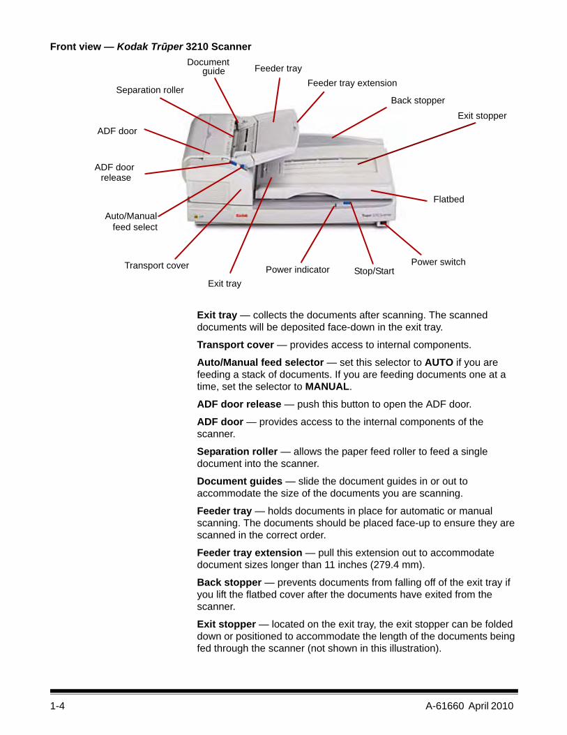
Front view — Kodak Trūper 3210 Scanner
Exit tray — collects the documents after scanning. The scanned documents will be deposited face-down in the exit tray.
Transport cover — provides access to internal components.
Auto/Manual feed selector — set this selector to AUTO if you are feeding a stack of documents. If you are feeding documents one at a time, set the selector to MANUAL.
ADF door release — push this button to open the ADF door.
ADF door — provides access to the internal components of the scanner.
Separation roller — allows the paper feed roller to feed a single document into the scanner.
Document guides — slide the document guides in or out to accommodate the size of the documents you are scanning.
Feeder tray — holds documents in place for automatic or manual scanning. The documents should be placed face-up to ensure they are scanned in the correct order.
Feeder tray extension — pull this extension out to accommodate document sizes longer than 11 inches (279.4 mm).
Back stopper — prevents documents from falling off of the exit tray if you lift the flatbed cover after the documents have exited from the scanner.
Exit stopper — located on the exit tray, the exit stopper can be folded down or positioned to accommodate the length of the documents being fed through the scanner (not shown in this illustration).
Power indicator Stop/StartPower switchTransport cover
Exit stopperBack stopper
Feeder tray extensionFeeder tray
Documentguide
ADF door
ADF doorrelease
Auto/Manualfeed select
Exit tray
Separation roller
Flatbed
A-61660 April 2010 1-5
Flatbed — for scanning bound books, documents that are badly torn or other exception documents.
Power switch — press this button to turn the scanner on or off.
Stop/Start button — starts or stops scanning.
Power indicator — indicates scanner status. See the section entitled, “Scanner LED status” in Chapter 7 for a description of the scanner states.
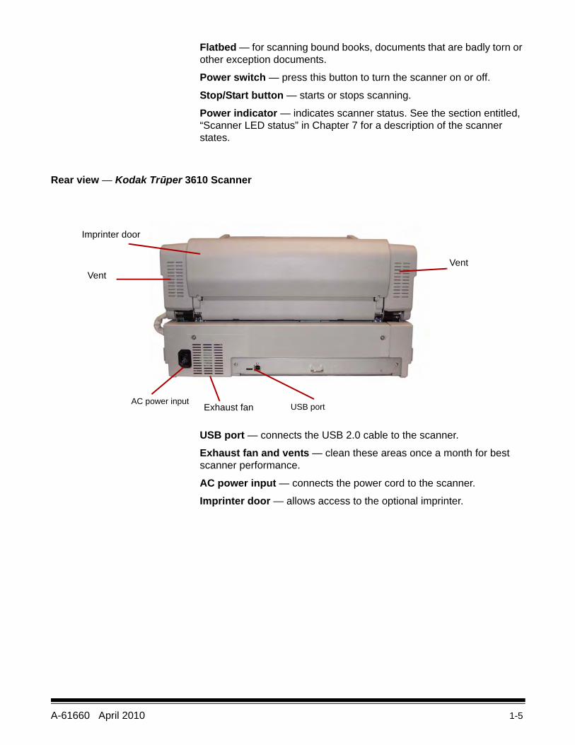
Rear view — Kodak Trūper 3610 Scanner
USB port — connects the USB 2.0 cable to the scanner.
Exhaust fan and vents — clean these areas once a month for best scanner performance.
AC power input — connects the power cord to the scanner.
Imprinter door — allows access to the optional imprinter.
USB portAC power input
Imprinter door
VentVent
Exhaust fan
1-6 A-61660 April 2010
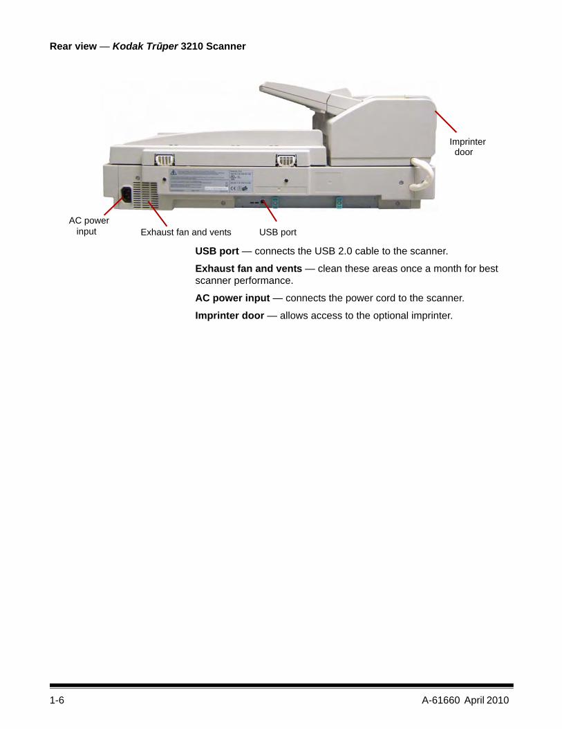
Rear view — Kodak Trūper 3210 Scanner
USB port — connects the USB 2.0 cable to the scanner.
Exhaust fan and vents — clean these areas once a month for best scanner performance.
AC power input — connects the power cord to the scanner.
Imprinter door — allows access to the optional imprinter.
USB portExhaust fan and ventsAC power
input
Imprinter door
A-61660 April 2010 1-7
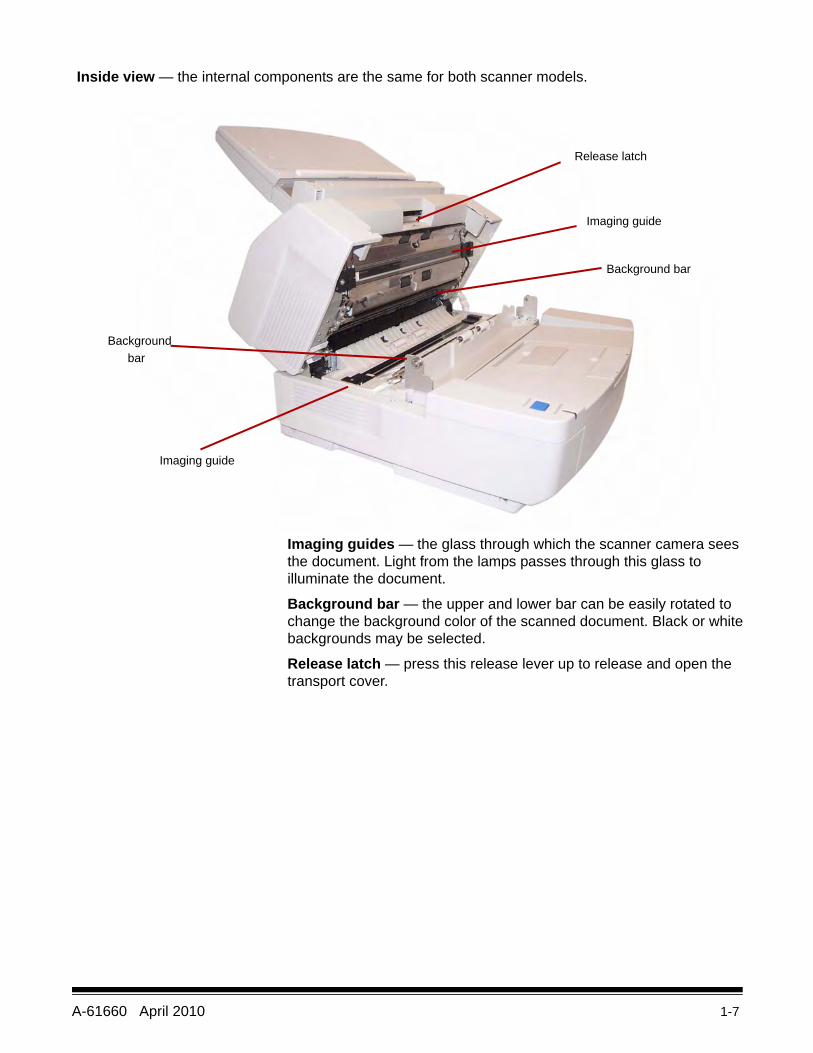
Inside view — the internal components are the same for both scanner models.
Imaging guides — the glass through which the scanner camera sees the document. Light from the lamps passes through this glass to illuminate the document.
Background bar — the upper and lower bar can be easily rotated to change the background color of the scanned document. Black or white backgrounds may be selected.
Release latch — press this release lever up to release and open the transport cover.
Background bar
Release latch
Background bar
Imaging guide
Imaging guide
A-61660 April 2010 2-1
2 Installation
Contents Installation checklist ........................................................................ 2-1Attaching the feeder tray................................................................. 2-2Making connections ........................................................................ 2-2Installing the Windows scanner driver ............................................ 2-3Installing the software ..................................................................... 2-4
Step 1: User utility....................................................................... 2-4Step 2: ISIS/TWAIN Driver ......................................................... 2-5Step 3: VirtualReScan ................................................................ 2-5Step 4: Applications.................................................................... 2-5User Utilities ............................................................................... 2-6
Viewing manuals............................................................................. 2-6
Installation checklist • After the scanner has been unpacked, it is recommended that you keep the original carton and all packing materials in case you need them later. See Appendix E, Repacking the Scanner for more information.
• Verify the computer system requirements. Refer to Appendix A, Specifications.
• Attach the feeder tray to the scanner. See the section entitled, “Attaching the feeder tray” later in this chapter.
• Connect the scanner. See the section entitled, “Making connections” later in this chapter.
• Install the software. See the section entitled, “Installing the software” later in this chapter.
You are now ready to scan. Refer to the instructions for your scanning or document management software application.
2-2 A-61660 April 2010
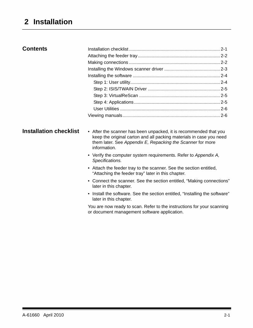
Attaching the feeder tray
1. Install the left side of the feeder tray by inserting the pin located at the left side of the feeder into the hole.
2. Install the right side of the feeder tray by inserting the pin located at the right side of the feeder into the hole. A small amount of pressure will be required to align the pin with the hole.
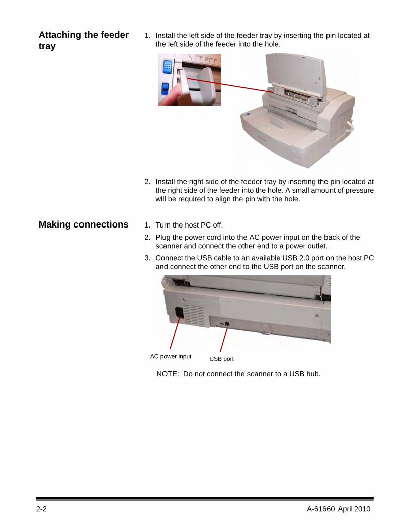
Making connections 1. Turn the host PC off.2. Plug the power cord into the AC power input on the back of the
scanner and connect the other end to a power outlet.3. Connect the USB cable to an available USB 2.0 port on the host PC
and connect the other end to the USB port on the scanner.
NOTE: Do not connect the scanner to a USB hub.
AC power input USB port
A-61660 April 2010 2-3
Installing the Windows scanner driver
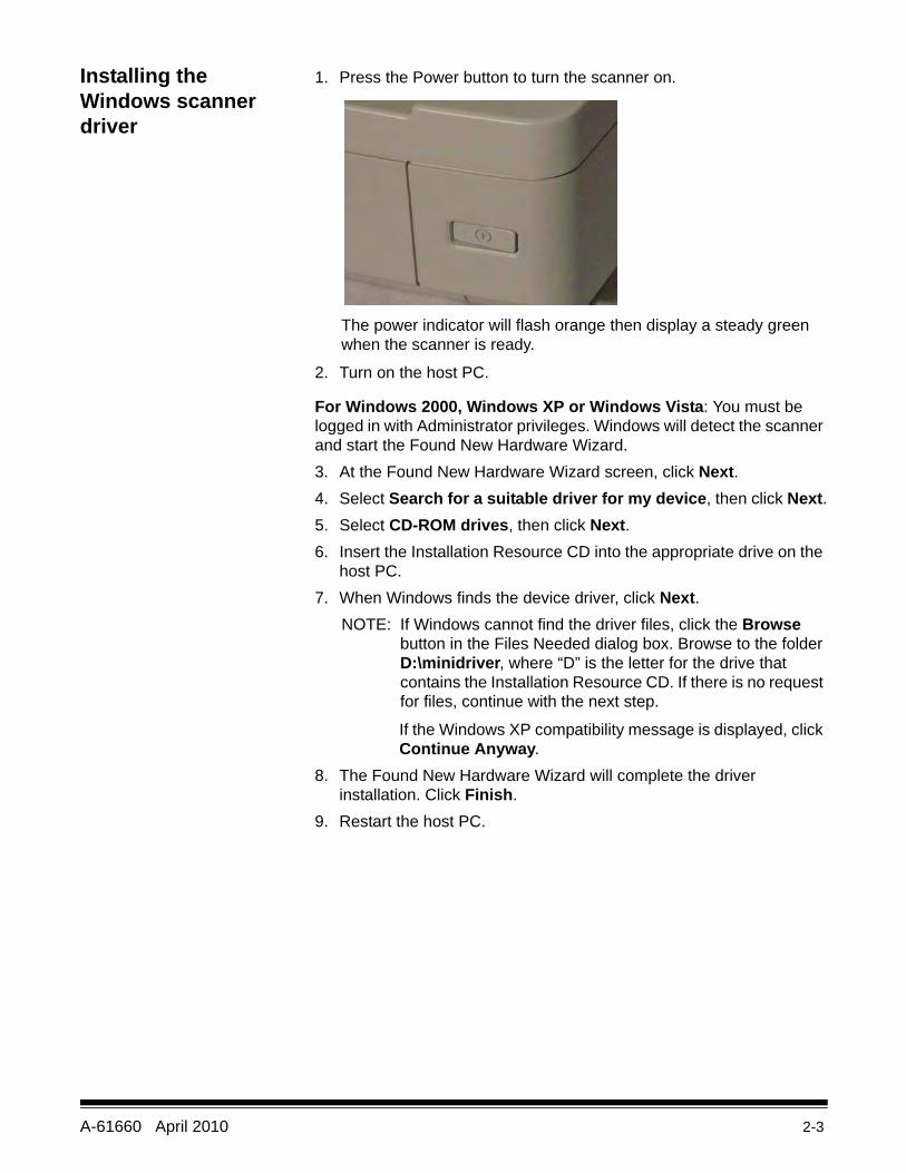
1. Press the Power button to turn the scanner on.
The power indicator will flash orange then display a steady green when the scanner is ready.
2. Turn on the host PC.
For Windows 2000, Windows XP or Windows Vista: You must be logged in with Administrator privileges. Windows will detect the scanner and start the Found New Hardware Wizard. 3. At the Found New Hardware Wizard screen, click Next.4. Select Search for a suitable driver for my device, then click Next.5. Select CD-ROM drives, then click Next.6. Insert the Installation Resource CD into the appropriate drive on the
host PC.7. When Windows finds the device driver, click Next.
NOTE: If Windows cannot find the driver files, click the Browse button in the Files Needed dialog box. Browse to the folder D:\minidriver, where “D” is the letter for the drive that contains the Installation Resource CD. If there is no request for files, continue with the next step.
If the Windows XP compatibility message is displayed, click Continue Anyway.
8. The Found New Hardware Wizard will complete the driver installation. Click Finish.
9. Restart the host PC.
2-4 A-61660 April 2010
Installing the software
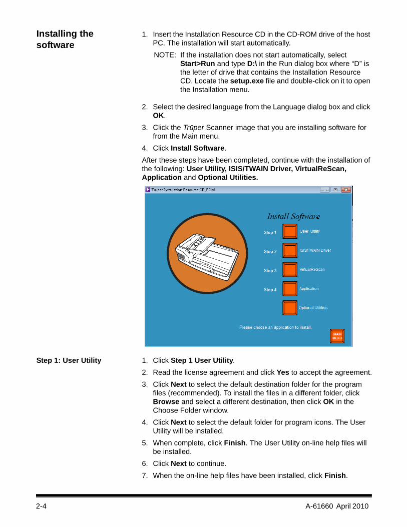
1. Insert the Installation Resource CD in the CD-ROM drive of the host PC. The installation will start automatically.NOTE: If the installation does not start automatically, select
Start>Run and type D:\ in the Run dialog box where “D” is the letter of drive that contains the Installation Resource CD. Locate the setup.exe file and double-click on it to open the Installation menu.
2. Select the desired language from the Language dialog box and click OK.
3. Click the Trūper Scanner image that you are installing software for from the Main menu.
4. Click Install Software.After these steps have been completed, continue with the installation of the following: User Utility, ISIS/TWAIN Driver, VirtualReScan, Application and Optional Utilities.
Step 1: User Utility 1. Click Step 1 User Utility. 2. Read the license agreement and click Yes to accept the agreement.3. Click Next to select the default destination folder for the program
files (recommended). To install the files in a different folder, click Browse and select a different destination, then click OK in the Choose Folder window.
4. Click Next to select the default folder for program icons. The User Utility will be installed.
5. When complete, click Finish. The User Utility on-line help files will be installed.
6. Click Next to continue.7. When the on-line help files have been installed, click Finish.
A-61660 April 2010 2-5
Step 2: ISIS/TWAIN Driver 1. Click Step 2 ISIS/TWAIN Driver.2. Read the license agreement and click Yes to accept the agreement. 3. Close all other Windows programs and click Next. 4. When the installation is complete, select Yes, I want to restart my
computer now and click Finish.
Step 3: VirtualReScan 1. Click Step 3 VirtualReScan. NOTE: It will take a few moments for the installation to begin. As
installation is progressing, messages will be displayed (i.e., VRS is installing....Please wait! This message will disappear when VRS has finished).
2. When the installation is complete, you will be prompted to restart the PC. Click Yes on the dialog box.
Step 4: Application 1. Click Step 4 Application to install your scanning application.
Driver Selection: Scanning Applications with VRS connectivityVirtualReScan is compatible with most scanning applications. When starting your scanning application, you may be requested to select a scanner or a scanner source. Depending on your application, select one of the following:
• For ImageControls applications, set Scanner Source to: Trūper 3210/3610 with SVRS.
• For ISIS applications, set Scanner Selection to: Kofax VRS Scanner. This is the certified ISIS driver for this configuration. DO NOT select Trūper 3210/3610.
• For TWAIN applications, set Scanner Selection to: Kofax Software VRS - TWAIN.
NOTE: Contact your application reseller for more information.
Scanning applications with Direct ISIS connectivityOccasionally, an ISIS application based on PixTools may not support the recommended VRS-based ISIS driver. Check with your application reseller to determine if your scanning application is compatible with VRS or requires the use of a Direct ISIS driver. For Direct ISIS connectivity, select the following driver:
• ISIS Application Scanner Selection: 3210/3610. This is the certified ISIS driver for direct connectivity.
2-6 A-61660 April 2010
Scanning applications with TWAIN connectivityOccasionally, the TWAIN application may not support the recommended VRS-based TWAIN driver. Check with your application reseller to determine if your scanning application is compatible with VRS or requires the use of a Direct TWAIN driver. For Direct TWAIN connectivity, select the following driver:
• TWAIN Application Scanner Selection: 3210/3610. This is the certified TWAIN driver for direct connectivity.
Optional Utilities 1. Click Optional Utilities from the Install Software screen.2. From the Optional Utilities screen, click ScanDemo to install this
application.
Viewing manuals The Kodak Trūper 3210/3610 User’s Guide and VRS manuals are available on the Installation Resource CD. NOTE: To view the manuals you will need Adobe Acrobat Reader.
1. Insert the Installation Resource CD in the PC.2. Select the desired language.3. Click View Manuals from the Main menu.4. Select the manual you want to view.
A-61660 April 2010 3-1
3 Using the Scanner
Contents Getting your scanner ready to scan ................................................ 3-1Determining your feeding mode................................................ 3-2Making scanner adjustments .................................................... 3-3Attaching the wire frame ........................................................... 3-4Changing the background bars................................................. 3-5Changing the background flatbed sheet ................................... 3-6Stop/Stop button functionality ................................................... 3-6
Getting your documents ready to scan ........................................... 3-8Scanning documents ...................................................................... 3-9Scanning with the flatbed (3210 Scanner) .................................... 3-11
Getting your scanner ready to scan
1. Press the power button to On (I). The power indicator on the front of the scanner will flash orange and then display a steady green. See the section entitled, “Scanner LED status” in Chapter 7 for more information regarding the power indicator.
2. After the power indicator on the scanner is a steady green, turn on your PC.
3. Determine your feeding mode: Auto for batch scanning; Manual for feeding one document at a time. See the next section, “Determining your feeding mode” for more information.
4. Adjust your side guides, end stop, change the background plates, etc. to accommodate your document scanning needs. See the section entitled, “Making scanner adjustments” later in this chapter for more information.
3-2 A-61660 April 2010
Determining your feeding mode
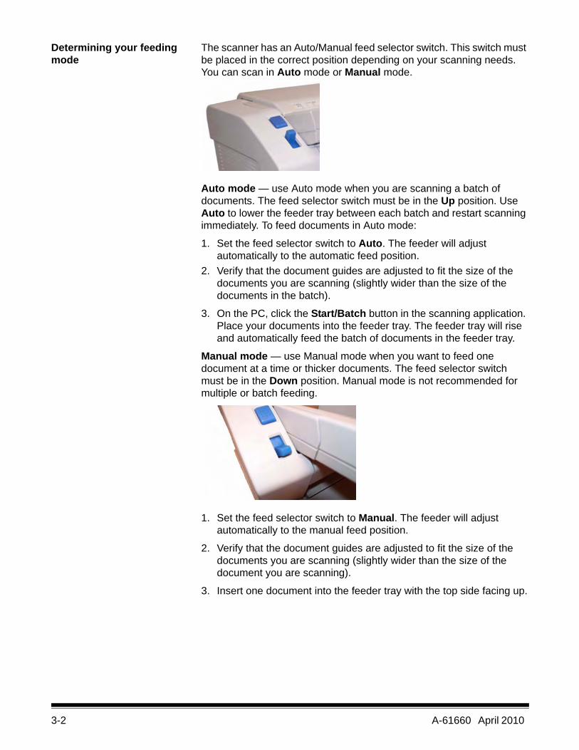
The scanner has an Auto/Manual feed selector switch. This switch must be placed in the correct position depending on your scanning needs. You can scan in Auto mode or Manual mode.
Auto mode — use Auto mode when you are scanning a batch of documents. The feed selector switch must be in the Up position. Use Auto to lower the feeder tray between each batch and restart scanning immediately. To feed documents in Auto mode:
1. Set the feed selector switch to Auto. The feeder will adjust automatically to the automatic feed position.
2. Verify that the document guides are adjusted to fit the size of the documents you are scanning (slightly wider than the size of the documents in the batch).
3. On the PC, click the Start/Batch button in the scanning application. Place your documents into the feeder tray. The feeder tray will rise and automatically feed the batch of documents in the feeder tray.
Manual mode — use Manual mode when you want to feed one document at a time or thicker documents. The feed selector switch must be in the Down position. Manual mode is not recommended for multiple or batch feeding.
1. Set the feed selector switch to Manual. The feeder will adjust automatically to the manual feed position.
2. Verify that the document guides are adjusted to fit the size of the documents you are scanning (slightly wider than the size of the document you are scanning).
3. Insert one document into the feeder tray with the top side facing up.
A-61660 April 2010 3-3
Making scanner adjustments
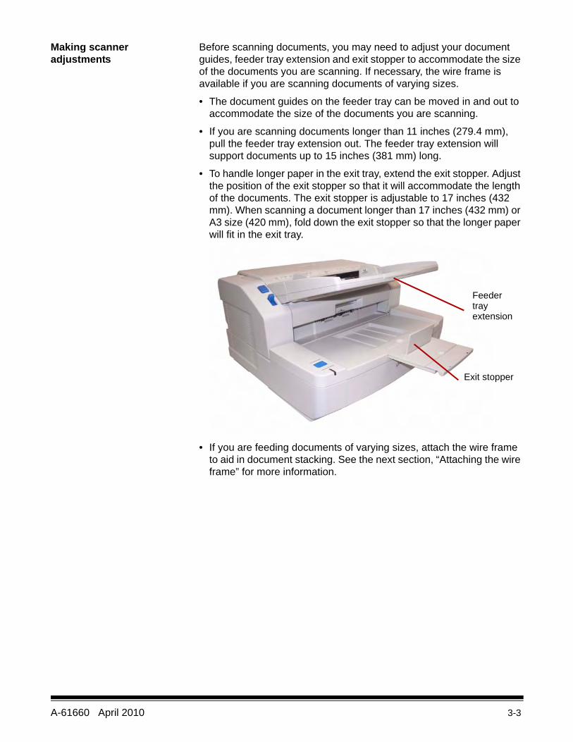
Before scanning documents, you may need to adjust your document guides, feeder tray extension and exit stopper to accommodate the size of the documents you are scanning. If necessary, the wire frame is available if you are scanning documents of varying sizes.
• The document guides on the feeder tray can be moved in and out to accommodate the size of the documents you are scanning.
• If you are scanning documents longer than 11 inches (279.4 mm), pull the feeder tray extension out. The feeder tray extension will support documents up to 15 inches (381 mm) long.
• To handle longer paper in the exit tray, extend the exit stopper. Adjust the position of the exit stopper so that it will accommodate the length of the documents. The exit stopper is adjustable to 17 inches (432 mm). When scanning a document longer than 17 inches (432 mm) or A3 size (420 mm), fold down the exit stopper so that the longer paper will fit in the exit tray.
• If you are feeding documents of varying sizes, attach the wire frame to aid in document stacking. See the next section, “Attaching the wire frame” for more information.
Feedertrayextension
Exit stopper
3-4 A-61660 April 2010
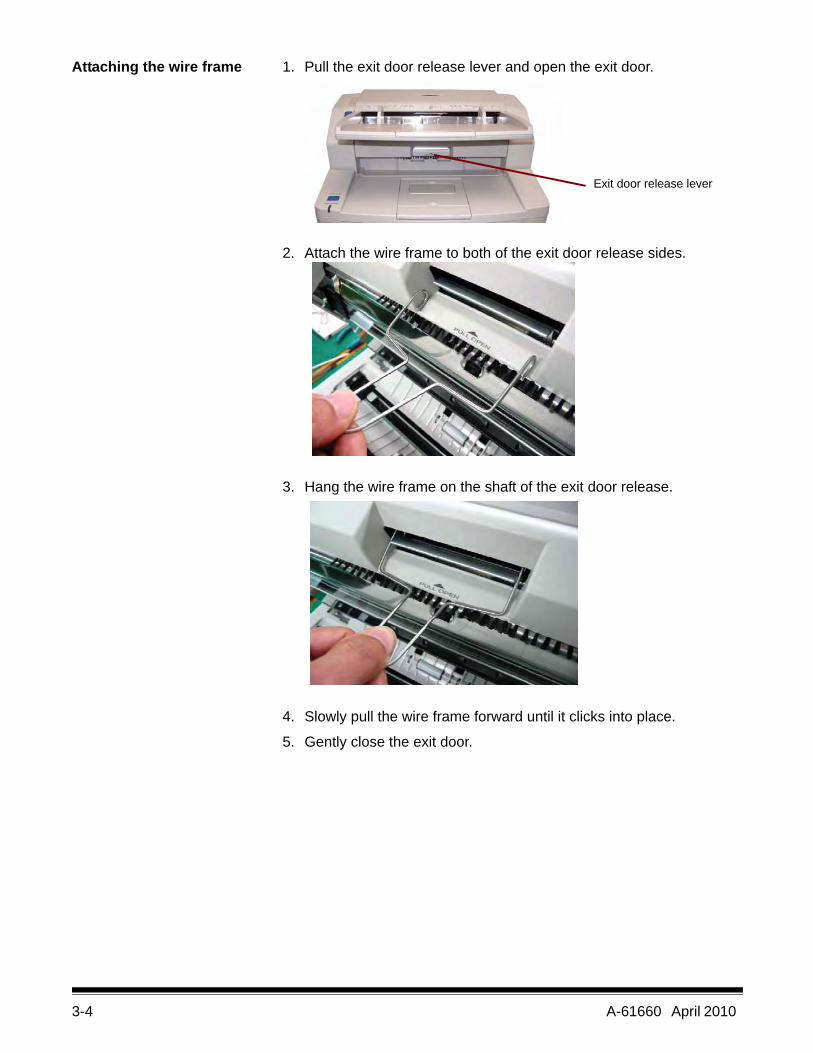
Attaching the wire frame 1. Pull the exit door release lever and open the exit door.
2. Attach the wire frame to both of the exit door release sides.
3. Hang the wire frame on the shaft of the exit door release.
4. Slowly pull the wire frame forward until it clicks into place.
5. Gently close the exit door.
Exit door release lever
A-61660 April 2010 3-5
Changing the background bars
There are two background bars located inside of the scanner; an upper background bar and a lower background bar. Each bar has a white side and a black side. These bars can be easily changed. The background color is important because is may affect the cropping quality of the scanned image.
Most of the time, you will scan your documents using the black background. The black background can improve imaging of documents with very light contrast data and increase color uniformity.
You should use the white background if you are scanning translucent documents. The white background will reduce black background bleed-through, which produces whiter images.
The background color set up in your scanning application, must match the color of the background bars.
To change the background bars:
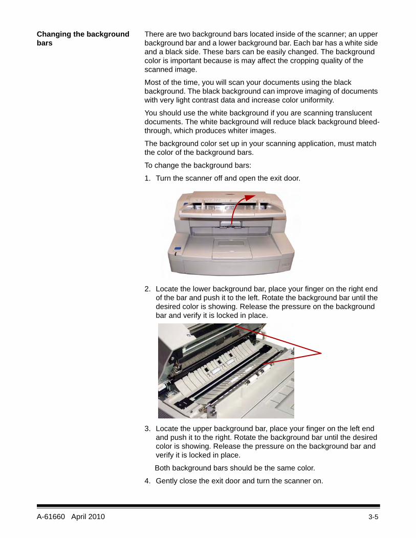
1. Turn the scanner off and open the exit door.
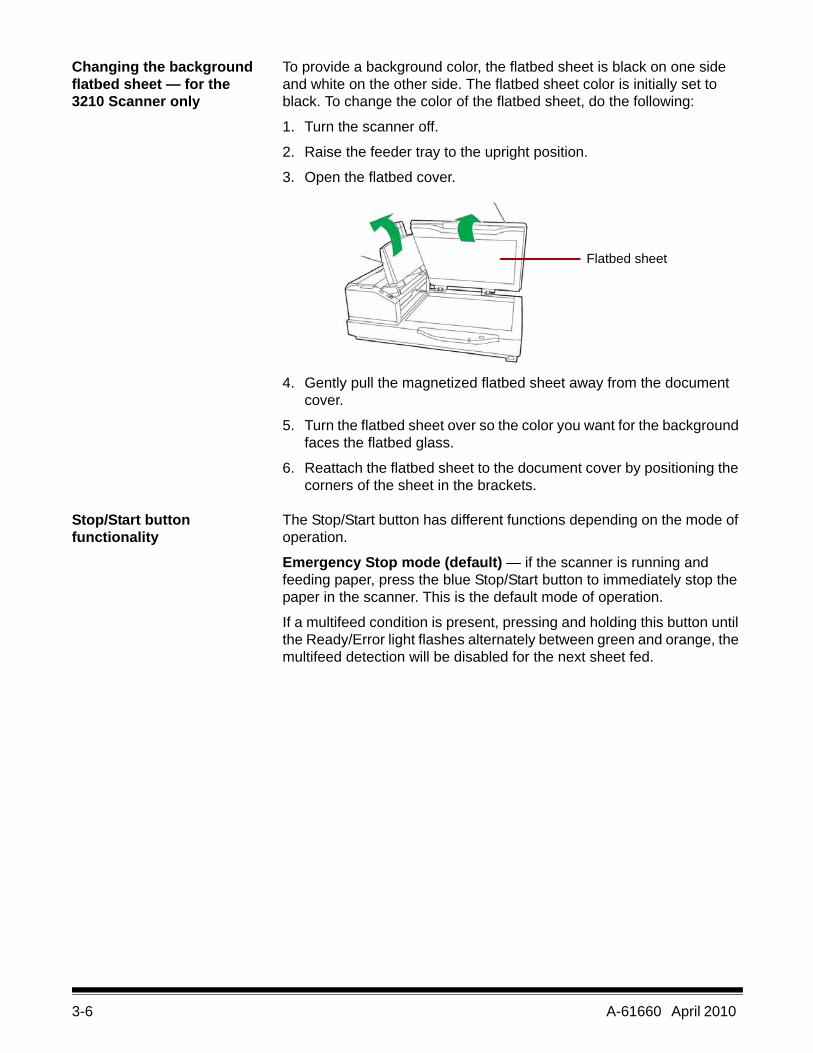
2. Locate the lower background bar, place your finger on the right end of the bar and push it to the left. Rotate the background bar until the desired color is showing. Release the pressure on the background bar and verify it is locked in place.
3. Locate the upper background bar, place your finger on the left end and push it to the right. Rotate the background bar until the desired color is showing. Release the pressure on the background bar and verify it is locked in place.
Both background bars should be the same color.
4. Gently close the exit door and turn the scanner on.
3-6 A-61660 April 2010
Changing the background flatbed sheet — for the 3210 Scanner only
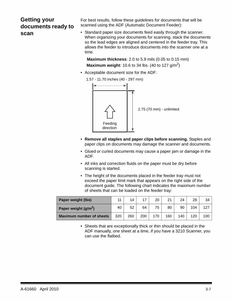
To provide a background color, the flatbed sheet is black on one side and white on the other side. The flatbed sheet color is initially set to black. To change the color of the flatbed sheet, do the following:
1. Turn the scanner off.
2. Raise the feeder tray to the upright position.
3. Open the flatbed cover.
4. Gently pull the magnetized flatbed sheet away from the document cover.
5. Turn the flatbed sheet over so the color you want for the background faces the flatbed glass.
6. Reattach the flatbed sheet to the document cover by positioning the corners of the sheet in the brackets.
Stop/Start button functionality
The Stop/Start button has different functions depending on the mode of operation.
Emergency Stop mode (default) — if the scanner is running and feeding paper, press the blue Stop/Start button to immediately stop the paper in the scanner. This is the default mode of operation.
If a multifeed condition is present, pressing and holding this button until the Ready/Error light flashes alternately between green and orange, the multifeed detection will be disabled for the next sheet fed.
Flatbed sheet
A-61660 April 2010 3-7
Getting your documents ready to scan
For best results, follow these guidelines for documents that will be scanned using the ADF (Automatic Document Feeder):
• Standard paper size documents feed easily through the scanner. When organizing your documents for scanning, stack the documents so the lead edges are aligned and centered in the feeder tray. This allows the feeder to introduce documents into the scanner one at a time.
Maximum thickness: 2.0 to 5.9 mils (0.05 to 0.15 mm)Maximum weight: 10.6 to 34 lbs. (40 to 127 g/m2)
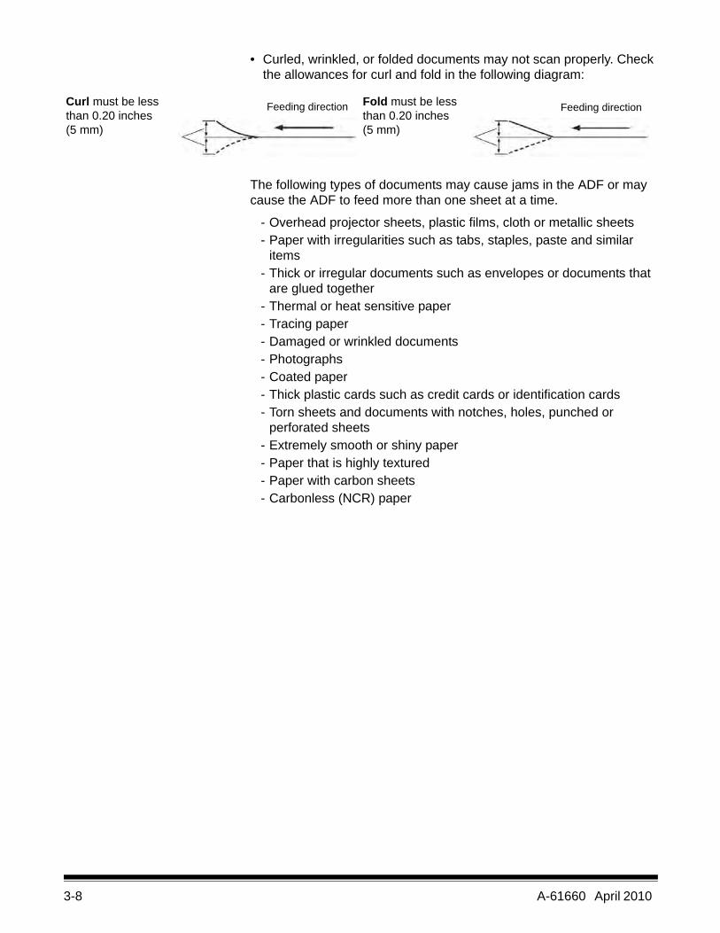
• Acceptable document size for the ADF:
• Remove all staples and paper clips before scanning. Staples and paper clips on documents may damage the scanner and documents.
• Glued or curled documents may cause a paper jam or damage in the ADF.
• All inks and correction fluids on the paper must be dry before scanning is started.
• The height of the documents placed in the feeder tray must not exceed the paper limit mark that appears on the right side of the document guide. The following chart indicates the maximum number of sheets that can be loaded on the feeder tray:
• Sheets that are exceptionally thick or thin should be placed in the ADF manually, one sheet at a time, if you have a 3210 Scanner, you can use the flatbed.
Feedingdirection
2.75 (70 mm) - unlimited
1.57 - 11.70 inches (40 - 297 mm)
Paper weight (lbs) 11 14 17 20 21 24 28 34
Paper weight (g/m2) 40 52 64 75 80 90 104 127
Maximum number of sheets 320 260 200 170 160 140 120 100
3-8 A-61660 April 2010
• Curled, wrinkled, or folded documents may not scan properly. Check the allowances for curl and fold in the following diagram:
The following types of documents may cause jams in the ADF or may cause the ADF to feed more than one sheet at a time.
- Overhead projector sheets, plastic films, cloth or metallic sheets- Paper with irregularities such as tabs, staples, paste and similar
items- Thick or irregular documents such as envelopes or documents that
are glued together- Thermal or heat sensitive paper- Tracing paper- Damaged or wrinkled documents- Photographs- Coated paper- Thick plastic cards such as credit cards or identification cards- Torn sheets and documents with notches, holes, punched or
perforated sheets- Extremely smooth or shiny paper- Paper that is highly textured- Paper with carbon sheets- Carbonless (NCR) paper
Curl must be less than 0.20 inches (5 mm)
Fold must be less than 0.20 inches (5 mm)
Feeding direction Feeding direction
A-61660 April 2010 3-9
Scanning documents 1. Prepare the batch of documents you want to scan by following the guidelines provided in the previous section, “Getting your documents ready to scan”.
2. Place the documents you want to scan in the feeder tray with the side to be scanned facing up. Slowly push the sheets into the scanner transport.
NOTES:
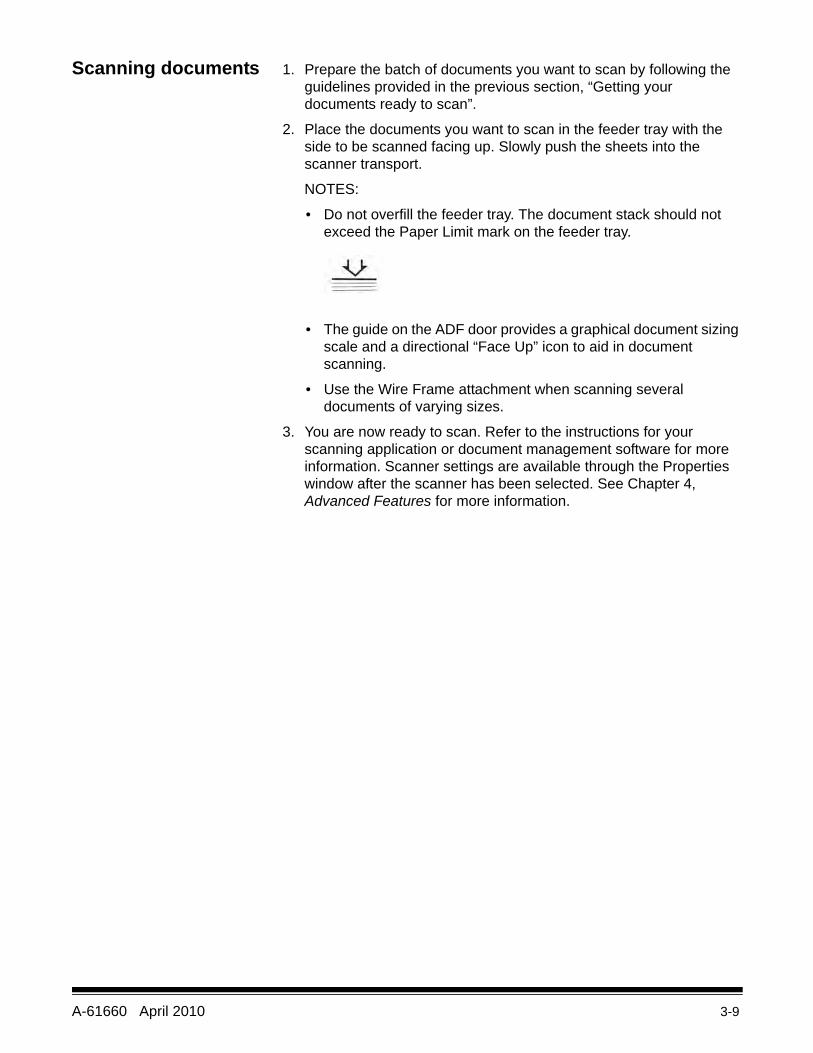
• Do not overfill the feeder tray. The document stack should not exceed the Paper Limit mark on the feeder tray.
• The guide on the ADF door provides a graphical document sizing scale and a directional “Face Up” icon to aid in document scanning.
• Use the Wire Frame attachment when scanning several documents of varying sizes.
3. You are now ready to scan. Refer to the instructions for your scanning application or document management software for more information. Scanner settings are available through the Properties window after the scanner has been selected. See Chapter 4, Advanced Features for more information.
3-10 A-61660 April 2010
Scanning with the flatbed (3210 Scanner)
You can use the flatbed on the 3210 Scanner to scan a single sheet, exception documents or documents that you do not want to take apart before scanning (e.g., books, magazines).
NOTE: Do not place floppy disks or any items containing magnetic media on the flatbed.
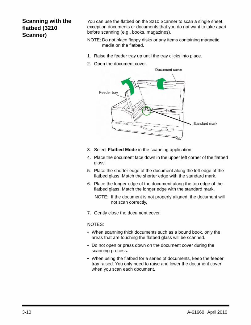
1. Raise the feeder tray up until the tray clicks into place.
2. Open the document cover.
3. Select Flatbed Mode in the scanning application.
4. Place the document face down in the upper left corner of the flatbed glass.
5. Place the shorter edge of the document along the left edge of the flatbed glass. Match the shorter edge with the standard mark.
6. Place the longer edge of the document along the top edge of the flatbed glass. Match the longer edge with the standard mark.
NOTE: If the document is not properly aligned, the document will not scan correctly.
7. Gently close the document cover.
NOTES:
• When scanning thick documents such as a bound book, only the areas that are touching the flatbed glass will be scanned.
• Do not open or press down on the document cover during the scanning process.
• When using the flatbed for a series of documents, keep the feeder tray raised. You only need to raise and lower the document cover when you scan each document.
Feeder tray
Document cover
Standard mark
A-61660 April 2010 4-1
4 Advanced Features
Contents Accessing Advanced features......................................................... 4-1Preset tab ................................................................................... 4-4Layout tab................................................................................... 4-5Paper Handling tab..................................................................... 4-7Image Processing tab............................................................... 4-10About tab .................................................................................. 4-14
This chapter provides information about advanced features that can be used with the Kodak Truper 3210 and 3610 Scanners. The controls for operating the Advanced Features are accessible within the VirtualReScan® (VRS) Interactive Viewer.
NOTES:
• When VRS is not installed, similar settings can be found in the Direct ISIS and TWAIN settings.
• Some functions shown in Advanced Features are disabled when using VRS.
4-2 A-61660 April 2010
Accessing Advanced features
To access the VRS Interactive Viewer, VRS Professional software must be loaded on the host PC that the scanner is connected to. VRS Professional will be active when the scanning application being used is launched and a VRS scan source is selected. There are three types of scan sources, depending on the VRS driver used.• VRS ImageControls®-based Applications• VRS ISIS-based Applications• VRS TWAIN-based ApplicationsNOTE: This User’s Guide only documents the VRS-based scanning
setup.
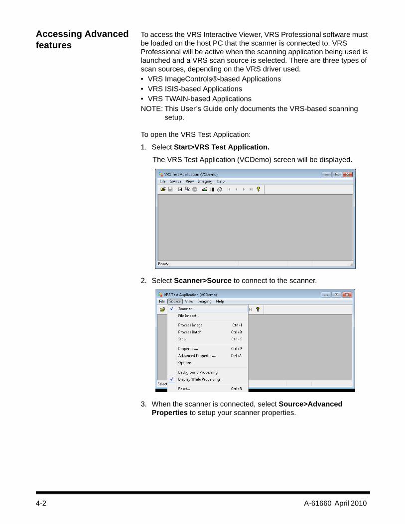
To open the VRS Test Application:
1. Select Start>VRS Test Application. The VRS Test Application (VCDemo) screen will be displayed.
2. Select Scanner>Source to connect to the scanner.
3. When the scanner is connected, select Source>Advanced Properties to setup your scanner properties.
A-61660 April 2010 4-3
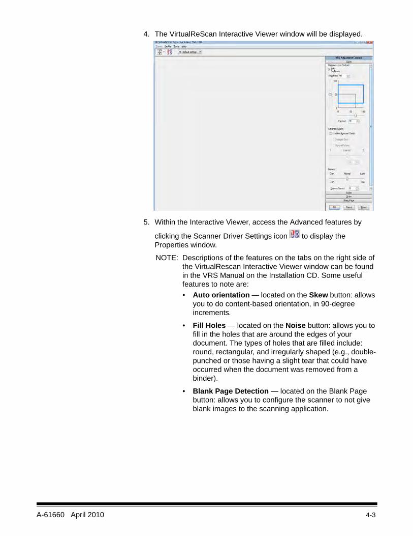
4. The VirtualReScan Interactive Viewer window will be displayed.
5. Within the Interactive Viewer, access the Advanced features by
clicking the Scanner Driver Settings icon to display the Properties window.
NOTE: Descriptions of the features on the tabs on the right side of the VirtualRescan Interactive Viewer window can be found in the VRS Manual on the Installation CD. Some useful features to note are:• Auto orientation — located on the Skew button: allows
you to do content-based orientation, in 90-degree increments.
• Fill Holes — located on the Noise button: allows you to fill in the holes that are around the edges of your document. The types of holes that are filled include: round, rectangular, and irregularly shaped (e.g., double-punched or those having a slight tear that could have occurred when the document was removed from a binder).
• Blank Page Detection — located on the Blank Page button: allows you to configure the scanner to not give blank images to the scanning application.
4-4 A-61660 April 2010
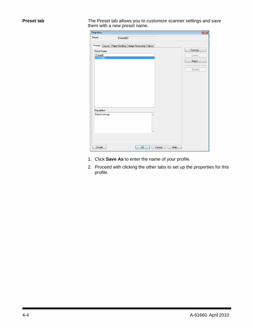
Preset tab The Preset tab allows you to customize scanner settings and savethem with a new preset name.
1. Click Save As to enter the name of your profile.
2. Proceed with clicking the other tabs to set up the properties for this profile.
A-61660 April 2010 4-5
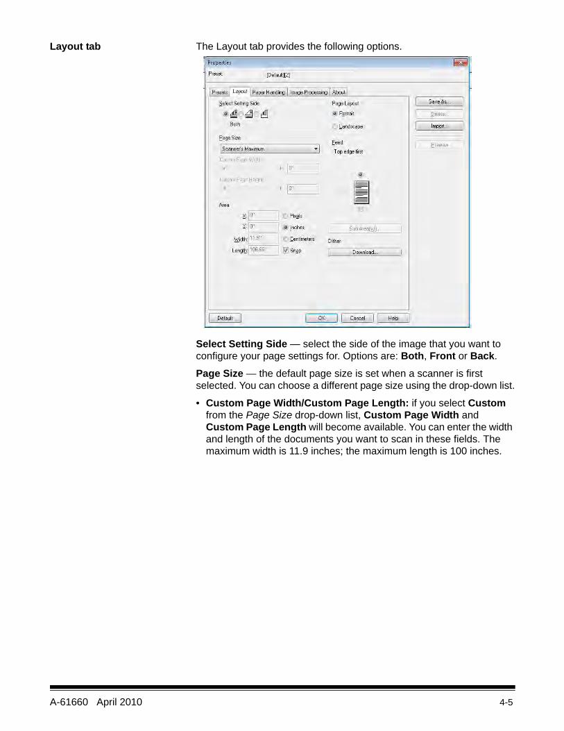
Layout tab The Layout tab provides the following options.
Select Setting Side — select the side of the image that you want to configure your page settings for. Options are: Both, Front or Back.
Page Size — the default page size is set when a scanner is first selected. You can choose a different page size using the drop-down list.
• Custom Page Width/Custom Page Length: if you select Custom from the Page Size drop-down list, Custom Page Width and Custom Page Length will become available. You can enter the width and length of the documents you want to scan in these fields. The maximum width is 11.9 inches; the maximum length is 100 inches.
4-6 A-61660 April 2010
Area — allows you to define the amount of image data which is returned to your PC.
• X: the distance from the left end of the scanner to the left-edge of the scanning area.
• Y: the position from the top end of the document to the top end of the scanning area.
• Width: the width of the scanning area.• Height: the height of the scanning area.
Select whether you want the area to be defined in Pixels, Inches or Centimeters.
• Snap ⎯ enable this option to control the dimensions of the preview area to fixed 1/8-inch increments.
Page Layout• Portrait: displays the image orientation in the shape of a
conventional portrait, where height is greater than width.
• Landscape: displays the image orientation in the shape of a conventional landscape painting, where width is greater than height.
Feed — allows you to select the way you place your documents in the scanner, Top edge first, Bottom edge first, Left edge first or Right edge first. • Sub Area(W): this option is only available when Length Control in the
Paper Handling tab is disabled.
A-61660 April 2010 4-7
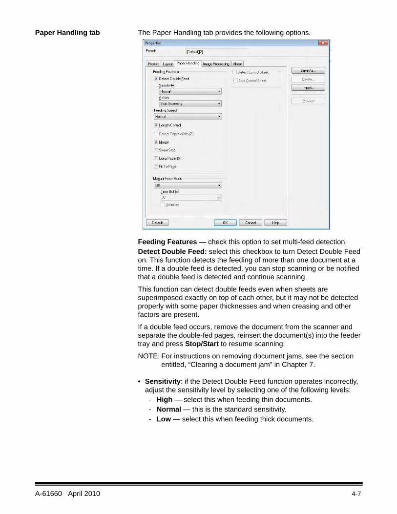
Paper Handling tab The Paper Handling tab provides the following options.
Feeding Features — check this option to set multi-feed detection.Detect Double Feed: select this checkbox to turn Detect Double Feed on. This function detects the feeding of more than one document at a time. If a double feed is detected, you can stop scanning or be notified that a double feed is detected and continue scanning.
This function can detect double feeds even when sheets are superimposed exactly on top of each other, but it may not be detected properly with some paper thicknesses and when creasing and other factors are present.
If a double feed occurs, remove the document from the scanner and separate the double-fed pages, reinsert the document(s) into the feeder tray and press Stop/Start to resume scanning.
NOTE: For instructions on removing document jams, see the section entitled, “Clearing a document jam” in Chapter 7.
• Sensitivity: if the Detect Double Feed function operates incorrectly, adjust the sensitivity level by selecting one of the following levels:- High — select this when feeding thin documents. - Normal — this is the standard sensitivity.- Low — select this when feeding thick documents.
4-8 A-61660 April 2010
• Action: select one of the following:- Beep — if selected, will signal an alert when a double-fed
document is detected.- Stop Scanning — stops the scanning process when a double-
fed document is detected. This is the default.
Feeding Speed — when scanning thin paper, badly creased paper, fragile paper, etc. you can change the speed of the scanner.
• Slow: this speed slows the documents that are fed through the ADF to about one-half the speed of Normal mode. The image quality in the Slow mode is the same as in the Normal mode.
• Normal: this is the normal speed of the scanner and is used for most document scanning.
NOTE: At resolutions above 300 dpi, the paper is fed at the same speed as in the Normal mode even if Slow has been specified.
Length Control — limits the length of the image to the actual page length. For example, if you turn off Length Control and select Page Size: Legal but scan a letter size document, the image size will be 14 inches long (11 inches for lettersize plus 3 inches of black on the bottom).
If this option is turned on, with the same Page Size: Legal selection and you feed a letter size document, the length will be limited to 11 inches (the length of the actual document).
It has no effect if the document is longer than the selected page size; the bottom is still cut off. For example, if you select Page Size: Letter and feed a legal-size document, the image will be limited to 11 inches whether this option is enabled or not.
Detect Paper Width (Z) — not available.
Margin — places a black border around the outside of the selected page size. This option is always on so the scanner can perform deskew and crop operations as needed.
Skew Stop — when enabled, the scanner will stop feeding if it detects that the document being fed is at a highly skewed angle.
Long Paper (X) — allows the scanner to scan a document virtually infinitely long. It will scan paper of any length, and generate images of whatever size is selected in the Layout tab.
For example, if this option is enabled and you select a page size of Letter (8.5 x 11 inches) and feed paper that is 220 inches long, the result will be 20 separate images that are 8.5 x 11 inches in size.
Fit to Page — reduces or enlarges the image to fit the size of the selected paper.
A-61660 April 2010 4-9
Manual Feed mode — select one of the following options for your scanning needs.
• Off — if you select this option, you will need to load the documents in the scanner and click Start Batch (or a button with similar name) in the scanning application to start scanning.
• On — select On when manually feeding documents. This should be selected when feeding mixed document types that are difficult to separate and may cause multifeeds. In this mode, the ADF is raised and the feeder rollers are not engaged until the document’s leading edge approaches the feeder roller.
• Start Button — if selected, the scanner will not start feeding until the Stop/Start button is pressed.
• Automatic — this is the standard mode of operation. In Automatic mode, the “out of paper” indication is displayed immediately after a batch has been scanned. This is the default.
• Timeout — allows you to set the amount of time the scanner will wait after the last document enters the transport before the transport timeout action is taken. You can specify a time delay setting from 1 to 300 seconds.
NOTE: The Timeout option is active in all Manual Feed Mode options except for Off.
• Unlimited — this is unlimited timeout. It is only available in the Start Button and Automatic modes.
• Detect Control Sheet — if this option is checked, the scanner will detect when a control sheet is placed in a batch and change the scanner's settings (i.e., color mode) accordingly.
• Skip Control Sheet — if this option is checked, the scanner will not generate an image of the scanned control sheet.
4-10 A-61660 April 2010
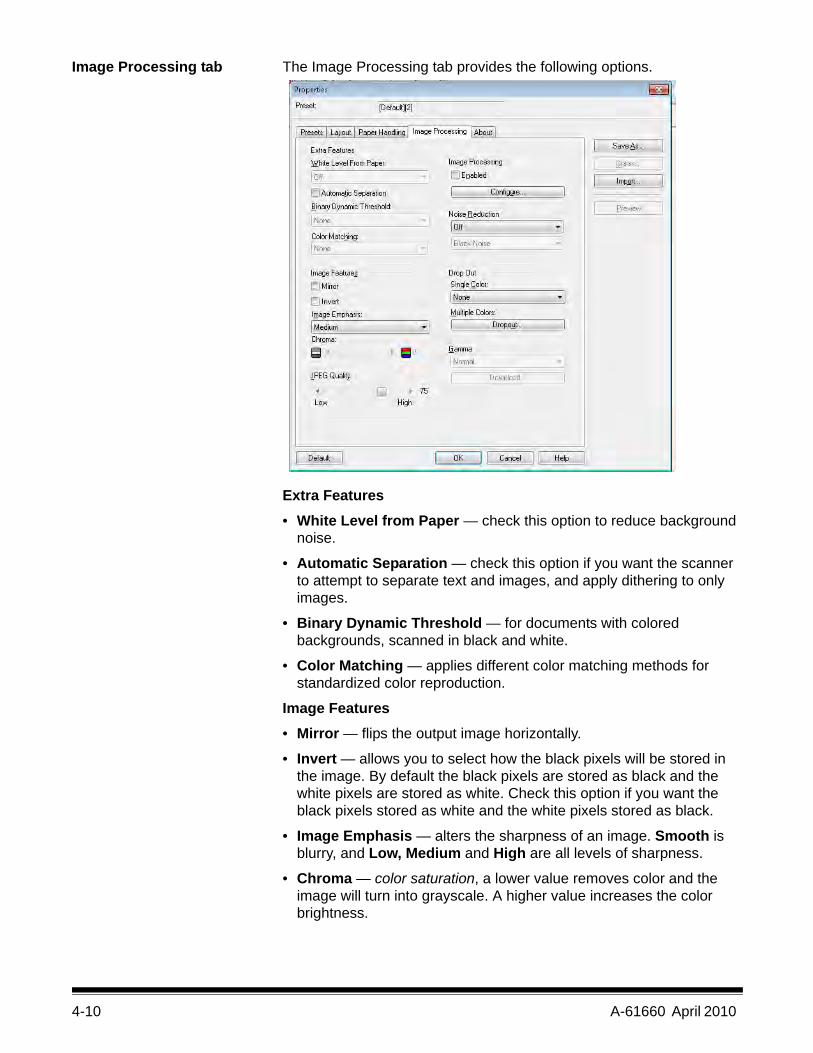
Image Processing tab The Image Processing tab provides the following options.
Extra Features
• White Level from Paper — check this option to reduce background noise.
• Automatic Separation — check this option if you want the scanner to attempt to separate text and images, and apply dithering to only images.
• Binary Dynamic Threshold — for documents with colored backgrounds, scanned in black and white.
• Color Matching — applies different color matching methods for standardized color reproduction.
Image Features• Mirror — flips the output image horizontally.
• Invert — allows you to select how the black pixels will be stored in the image. By default the black pixels are stored as black and the white pixels are stored as white. Check this option if you want the black pixels stored as white and the white pixels stored as black.
• Image Emphasis — alters the sharpness of an image. Smooth is blurry, and Low, Medium and High are all levels of sharpness.
• Chroma — color saturation, a lower value removes color and the image will turn into grayscale. A higher value increases the color brightness.
A-61660 April 2010 4-11
JPEG Quality — select a compression value from 1 to 100. The lower the value will provide the maximum compression which produces the smallest image size. The higher the value will provide the least amount of compression which produces the largest image size.
Image Processing — not available.
Noise Reduction — reduces random noise by converting a single black pixel to white when it is completely surrounded by white pixels or by converting a single white pixel to black when it is completely surrounded by black pixels. Select to remove Black Noise or White Noise.
Drop Out — color dropout allows you to remove a one or more colors from a color document when scanning in Black and White mode. Up to 6 colors can be dropped out.
• Single Color: allows you to delete colored (red, green or blue) text or lines printed on documents. Single color dropout can only be used with binary images in black and white or binary modes and can be set independently for the front and back of a document. This functionality is primarily used in OCR (Optical Character Reading) to dropout form lines.
NOTE: Depending on the scanning conditions and colors, it may not be possible to delete the specified colors completely.
To drop out a single color, select Red, Green or Blue from the Single Color drop-down list.
4-12 A-61660 April 2010
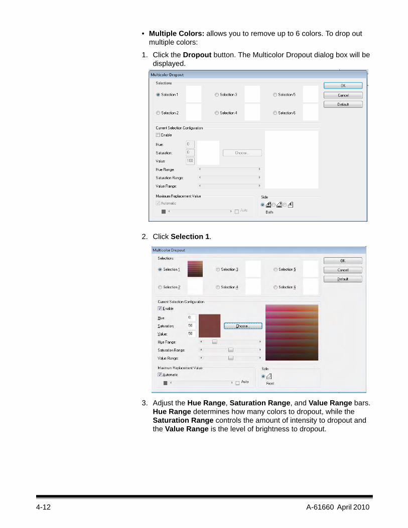
• Multiple Colors: allows you to remove up to 6 colors. To drop out multiple colors:
1. Click the Dropout button. The Multicolor Dropout dialog box will be displayed.
2. Click Selection 1.
3. Adjust the Hue Range, Saturation Range, and Value Range bars. Hue Range determines how many colors to dropout, while the Saturation Range controls the amount of intensity to dropout and the Value Range is the level of brightness to dropout.
A-61660 April 2010 4-13
NOTES:
• The default values for Hue, Saturation and Value are typically accurate. However, if the dropout color requires adjusting, the Hue, Saturation and Value numbers can be modified manually.
• Hue determines the color. Saturation defines the intensity of the color. Value controls the brightness of the color.
4. To add additional dropout colors, click the next Selection radio button and repeat steps 4 - 7.
5. In the Maximum Replacement Value section, do one of the following:
• Select Automatic and adjust the bar accordingly.• Select Auto to completely dropout the color.
To disable dropout colors:
• Select the Selection radio button for the color you want to disable and then uncheck Enable.
NOTE: Any and all of the selections can be active at the same time.
Gamma — this is a shading adjustment.
• Normal: uses a predefined curve that works best under most conditions in all color modes.
• For CRT: select if you intend to view the images on a display.
• User Downloaded: to download your own curve formula.
• Linear: no curve, straight line formula.
4-14 A-61660 April 2010
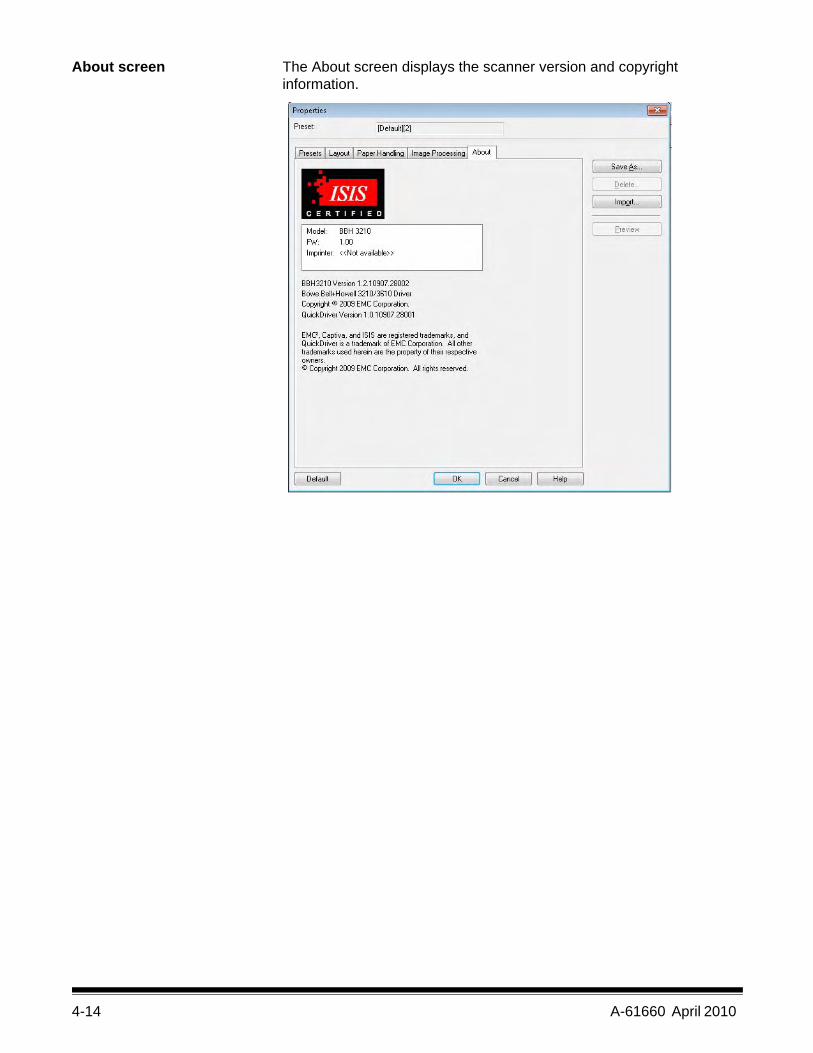
About screen The About screen displays the scanner version and copyright information.
A-61660 April 2010 5-1
5 User Utility
Contents Starting the User Utility ................................................................... 5-1The User Utility dialog box .............................................................. 5-1
The User Utility is a software program used to maintain and troubleshoot the Kodak Trūper 3210 and 3610 Scanners. The User Utility is installed as part of the scanner’s software installation.If the Trūper User Utility icon is not on your desktop, see the section entitled, “Installing the software” in Chapter 2.
Starting the User Utility
• Click the User Utility icon or click the Start>Programs>Kodak> Scanner Tools.
NOTE: When starting the User Utility, the Select Scanner dialog box may be displayed. If this dialog box is displayed, select the desired scanner from the drop-down list.
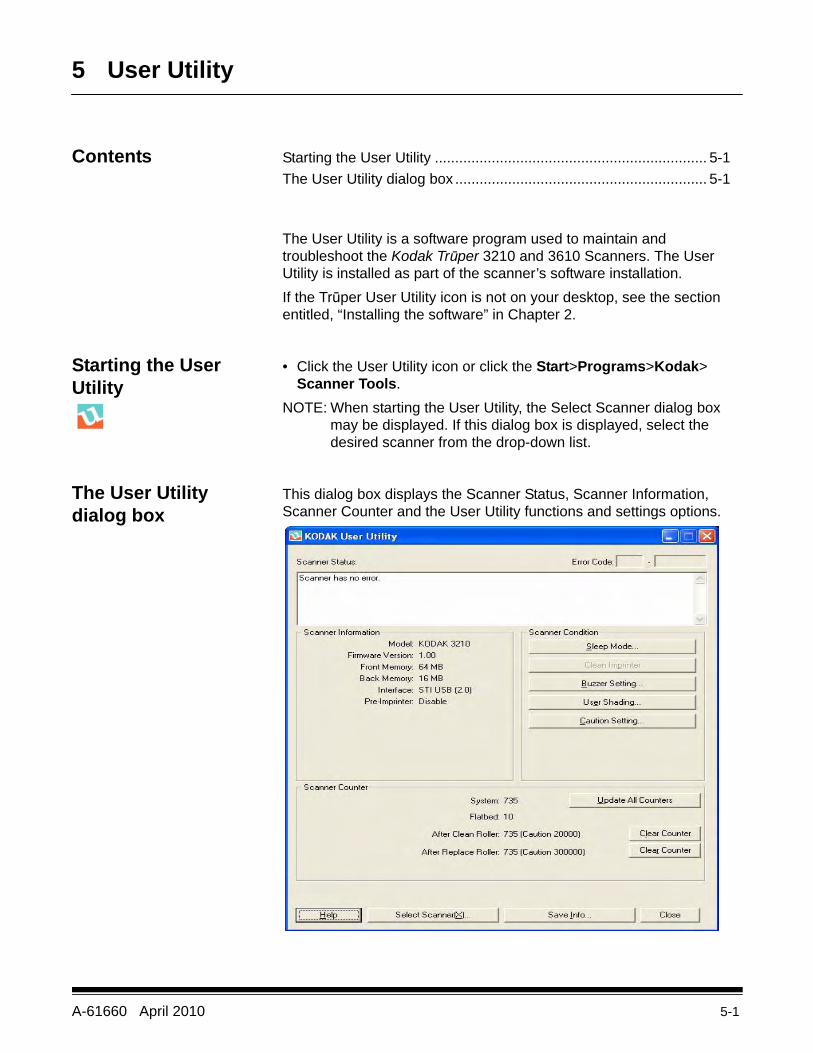
The User Utility dialog box
This dialog box displays the Scanner Status, Scanner Information, Scanner Counter and the User Utility functions and settings options.
5-2 A-61660 April 2010
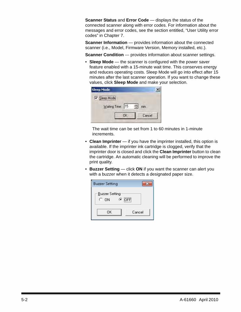
Scanner Status and Error Code — displays the status of the connected scanner along with error codes. For information about the messages and error codes, see the section entitled, “User Utility error codes” in Chapter 7.Scanner Information — provides information about the connected scanner (i.e., Model, Firmware Version, Memory installed, etc.).Scanner Condition — provides information about scanner settings.• Sleep Mode — the scanner is configured with the power saver
feature enabled with a 15-minute wait time. This conserves energy and reduces operating costs. Sleep Mode will go into effect after 15 minutes after the last scanner operation. If you want to change these values, click Sleep Mode and make your selection.
The wait time can be set from 1 to 60 minutes in 1-minute increments.
• Clean Imprinter — if you have the imprinter installed, this option is available. If the imprinter ink cartridge is clogged, verify that the imprinter door is closed and click the Clean Imprinter button to clean the cartridge. An automatic cleaning will be performed to improve the print quality.
• Buzzer Setting — click ON if you want the scanner can alert you with a buzzer when it detects a designated paper size.
A-61660 April 2010 5-3
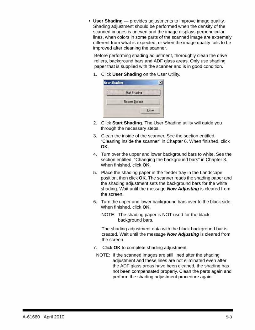
• User Shading — provides adjustments to improve image quality. Shading adjustment should be performed when the density of the scanned images is uneven and the image displays perpendicular lines, when colors in some parts of the scanned image are extremely different from what is expected, or when the image quality fails to be improved after cleaning the scanner.Before performing shading adjustment, thoroughly clean the drive rollers, background bars and ADF glass areas. Only use shading paper that is supplied with the scanner and is in good condition.
1. Click User Shading on the User Utility.
2. Click Start Shading. The User Shading utility will guide you through the necessary steps.
3. Clean the inside of the scanner. See the section entitled, “Cleaning inside the scanner” in Chapter 6. When finished, click OK.
4. Turn over the upper and lower background bars to white. See the section entitled, “Changing the background bars” in Chapter 3. When finished, click OK.
5. Place the shading paper in the feeder tray in the Landscape position, then click OK. The scanner reads the shading paper and the shading adjustment sets the background bars for the white shading. Wait until the message Now Adjusting is cleared from the screen.
6. Turn the upper and lower background bars over to the black side. When finished, click OK. NOTE: The shading paper is NOT used for the black
background bars.
The shading adjustment data with the black background bar is created. Wait until the message Now Adjusting is cleared from the screen.
7. Click OK to complete shading adjustment.NOTE: If the scanned images are still lined after the shading
adjustment and these lines are not eliminated even after the ADF glass areas have been cleaned, the shading has not been compensated properly. Clean the parts again and perform the shading adjustment procedure again.
5-4 A-61660 April 2010
• Restoring shading to the default: you can restore shading adjustment data to the default setting by clicking Restore Default on the User Shading dialog box. Restore the default if the image quality deteriorates or has not improved as a result of the shading adjustment process.
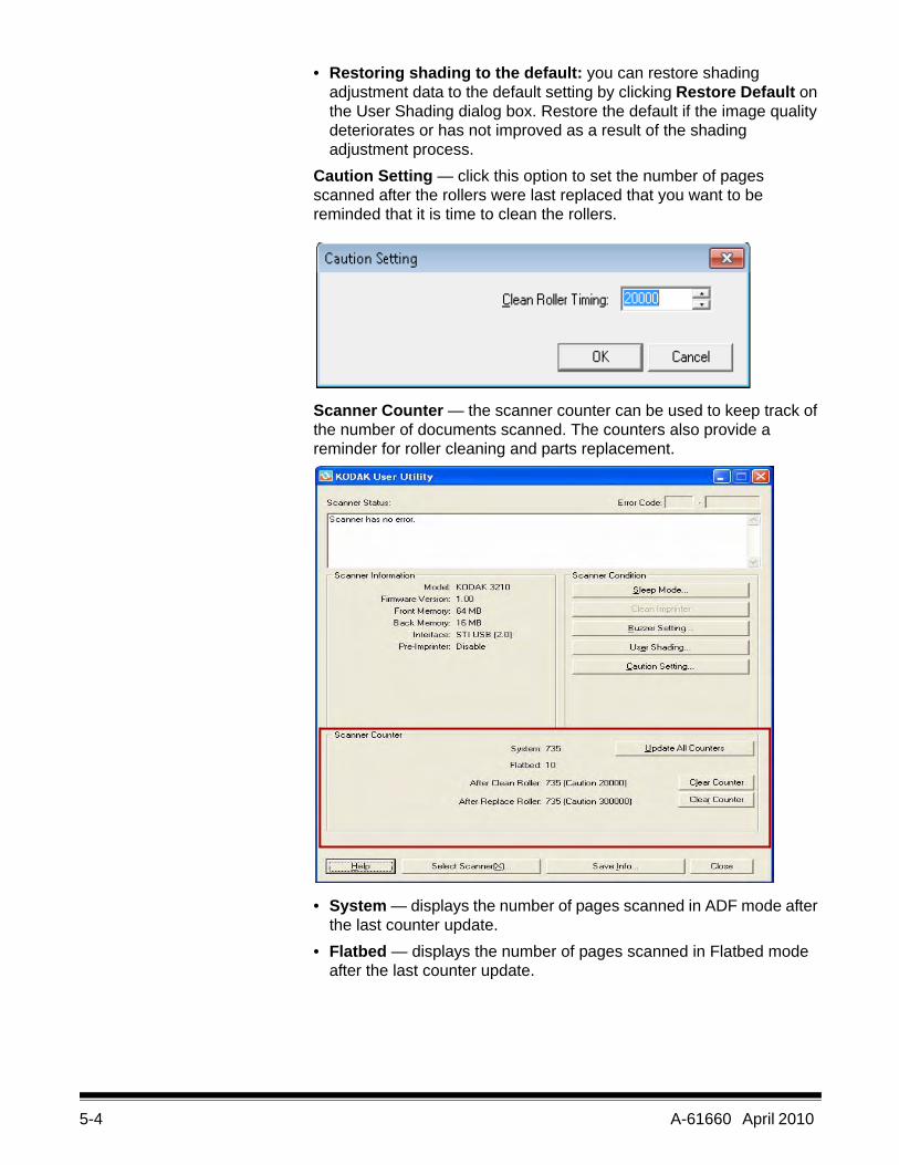
Caution Setting — click this option to set the number of pages scanned after the rollers were last replaced that you want to be reminded that it is time to clean the rollers.
Scanner Counter — the scanner counter can be used to keep track of the number of documents scanned. The counters also provide a reminder for roller cleaning and parts replacement.
• System — displays the number of pages scanned in ADF mode after the last counter update.
• Flatbed — displays the number of pages scanned in Flatbed mode after the last counter update.
A-61660 April 2010 5-5
• After Clean Roller — displays the number of pages scanned after the rollers were last cleaned. When the After Clean Roller number is greater than the Warning number, the rollers need to be cleaned. (The Warning number indicates how many pages can be scanned after roller cleaning before the rollers need to be cleaned again.)
• After Replace Roller — displays the number of pages scanned after the rollers were last replaced. When the After Replace Roller number is greater than the Warning number, the rollers need to be replaced. (The Warning number indicates how many pages can be scanned with a new set of rollers before the rollers need to be replaced.)
• Update All Counters — updates the counter display to the most current numbers. Document scanning operations do not automatically update the counter displays.
• Clear Counter buttons — there are two Clear Counter buttons, one to clear the After Clean Roller display and one to clear the After Replace Roller display.- After you clean the rollers, click Clear Counter for After Clean
Roller and reset the number to zero.
- After you replace the rollers, click Clear Counter for After Replace Roller and reset the counter to zero.
Help — opens the Kodak Trūper 3210 and 3610 Scanners User’s Guide in PDF file format. Select Scanner(X) — opens the Select Scanner dialog box. If more than one scanner is connected to the computer, you can use the Select Scanner dialog box to select a different scanner. The User Utility functions and settings will then apply to the selected scanner. To select a different scanner:1. Click Select Scanner(X).2. Click the drop-down list and select a different scanner, then click
OK.Save Info — allows you to save current scanner and computer system information to a log file.1. Click Save info.2. In the Save in drop-down list, browse to find a location to save the
log file.3. In the File name box, type a file name for the log file (the default file
name is Scanner.log).
5-6 A-61660 April 2010
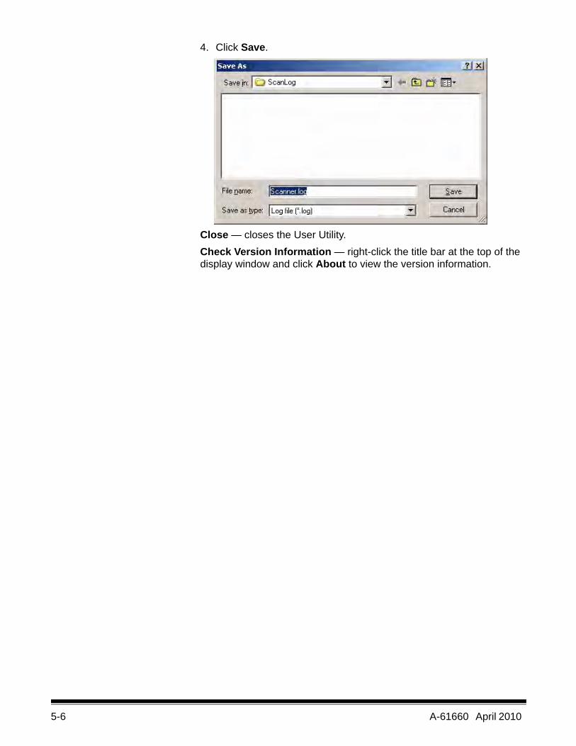
4. Click Save.
Close — closes the User Utility.Check Version Information — right-click the title bar at the top of the display window and click About to view the version information.
A-61660 April 2010 6-1
6 Maintenance
Contents Cleaning procedures....................................................................... 6-1Roller cleaning............................................................................ 6-2Cleaning the outside of the scanner........................................... 6-2Cleaning inside the scanner ....................................................... 6-2Cleaning the rollers in the ADF area .......................................... 6-3Cleaning the rollers in the Exit area ........................................... 6-5Cleaning the background bars and imaging guides ................... 6-6Cleaning the sensors.................................................................. 6-6Cleaning the flatbed ................................................................... 6-9
Replacing consumables................................................................ 6-10Supplies and consumables .......................................................... 6-13
Cleaning procedures The following cleaning guidelines and procedures will help ensure best scanner performance.
NOTE: Use only the recommended cleaning supplies when cleaning the scanner.
• If paper jamming, marking or multiple-sheet feeding occurs frequently, clean the rollers, sensors and double feed detector as described in this section. If paper jamming, marking or double feeding occurs frequently even after cleaning, you may need to change the rollers.
• To maintain scanning quality, clean the scanner at least once a week or after 20,000 sheets have been scanned, whichever comes first. To determine the number of sheets scanned, use the Trūper User Utility.
• Be sure the documents you scan are clean. If the documents you scan are dirty, the scanner components will also become dirty.
• When scanning with the flatbed, if black dots or white patches appear in the scanned results, open the document cover and clean the flatbed glass and flatbed sheet using Staticide wipes. If black or white lines appear on the scanned images, clean the imaging guides and the background bars.
• It is recommended that you clean all of the rollers at the same time.
6-2 A-61660 April 2010
Roller cleaning pads Review the following information before using the roller cleaning pads • If you need more information about the roller cleaning pads, refer to
the Material Safety Data Sheet (MSDS). See the Kodak website at: www.kodak.com/go/msds.
• Additional roller cleaning pads can be purchased. See “Supplies and consumables” later in this chapter for ordering information.
NOTE: Use the roller cleaning pads immediately after opening the bag. If the bag remains open for a long period of time, the alcohol cleaning solution will evaporate and the cleaning pad will not be effective.
Cleaning the outside of the scanner
Clean the outside of the scanner at least once a month.
1. Turn the scanner off.
2. Clean the exit tray, the feeder and feeder tray, ADF cover and other surfaces with a soft cloth.
3. Clean the feeder tray and exit tray of the ADF at least once a month or more often if there is an accumulation of dirt, dust and grime.
4. Use a brush to remove dirt and dust from the exhaust fan vent and the two vents on the left and right side on the back of the scanner.
Cleaning inside the scanner
If paper jamming, marking, or multiple-sheet feeding occurs frequently, clean the rollers, sensors and double feed detector as described in this section. To maintain scanning quality, clean the scanner components frequently: Clean inside the scanner at least once per week or after 20,000 sheets have been scanned, whichever comes first.
NOTE: To determine the number of sheets scanned, use the Trūper User Utility. See the Chapter 5, Trūper User Utility for more information.
The following guidelines are for cleaning inside the scanner:
• Be sure the documents you are scanning are as clean as possible to minimize frequent scanner dirt and dust buildup.
• When cleaning the rollers, hold the roller to prevent it from rotating, then horizontally wipe the roller from side to side. Turn the roller as you continue to wipe until the entire roller has been cleaned.
• If black or white lines appear on the scanned images, clean the imaging guides and the background bars as described in the section entitled, “Cleaning the background bars and imaging guides” later in this chapter.
• If paper jamming, marking, or multi-sheet feeding occurs frequently even after cleaning, you may need to change the rollers as described in the section entitled, “Replacing consumables” later in this chapter.
Cleaning the rollers in the ADF area
Cleaning the paper feeder roller and separation roller1. Turn the scanner off.
A-61660 April 2010 6-3
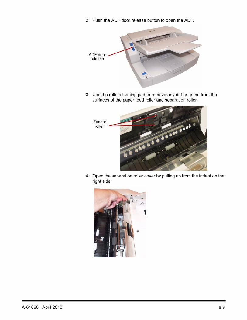
2. Push the ADF door release button to open the ADF.
3. Use the roller cleaning pad to remove any dirt or grime from the surfaces of the paper feed roller and separation roller.
4. Open the separation roller cover by pulling up from the indent on the right side.
ADF door release
Feeder roller
6-4 A-61660 April 2010
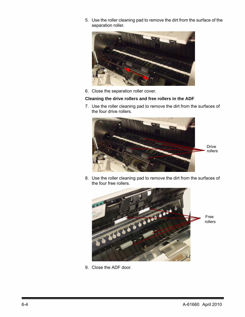
5. Use the roller cleaning pad to remove the dirt from the surface of the separation roller.
6. Close the separation roller cover.
Cleaning the drive rollers and free rollers in the ADF7. Use the roller cleaning pad to remove the dirt from the surfaces of
the four drive rollers.
8. Use the roller cleaning pad to remove the dirt from the surfaces of the four free rollers.
9. Close the ADF door.
Drive rollers
Freerollers
A-61660 April 2010 6-5
Cleaning the rollers in the Exit area
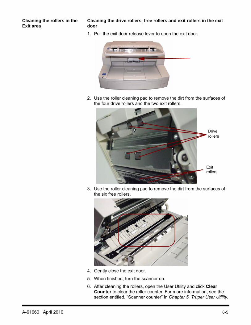
Cleaning the drive rollers, free rollers and exit rollers in the exit door1. Pull the exit door release lever to open the exit door.
2. Use the roller cleaning pad to remove the dirt from the surfaces of the four drive rollers and the two exit rollers.
3. Use the roller cleaning pad to remove the dirt from the surfaces of the six free rollers.
4. Gently close the exit door.
5. When finished, turn the scanner on.
6. After cleaning the rollers, open the User Utility and click Clear Counter to clear the roller counter. For more information, see the section entitled, “Scanner counter” in Chapter 5, Trūper User Utility.
Driverollers
Exitrollers
6-6 A-61660 April 2010
Cleaning the background bars and imaging guides
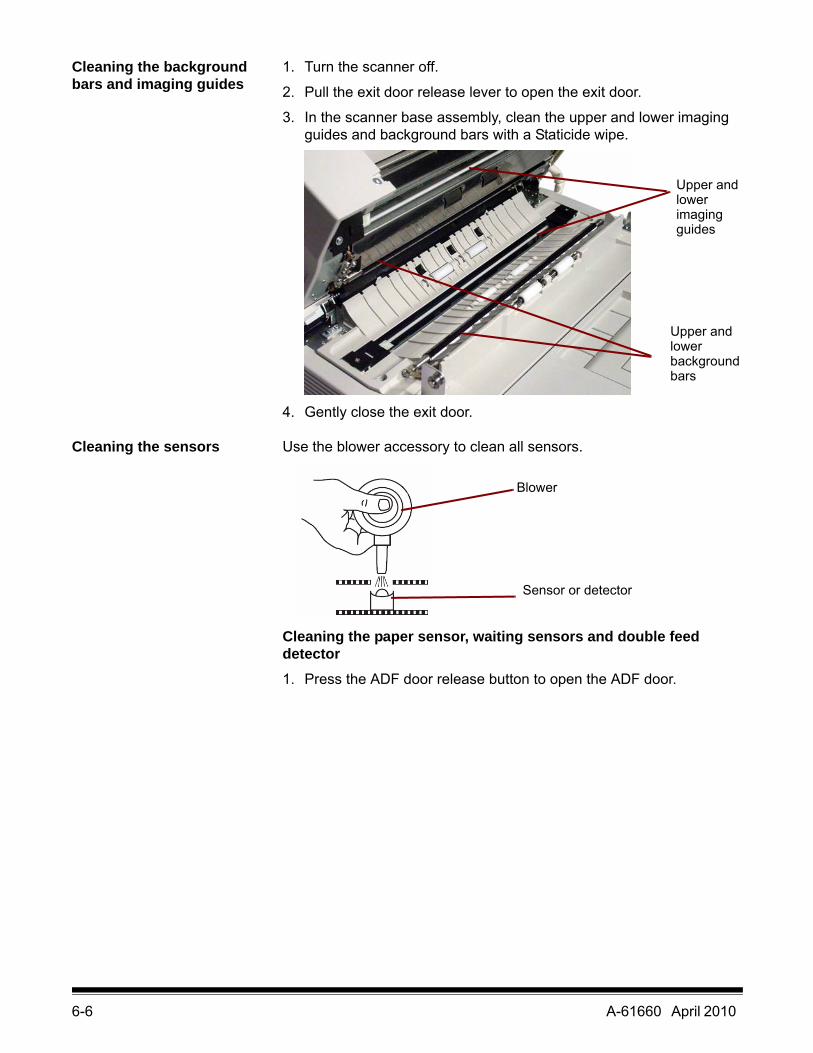
1. Turn the scanner off.
2. Pull the exit door release lever to open the exit door.
3. In the scanner base assembly, clean the upper and lower imaging guides and background bars with a Staticide wipe.
4. Gently close the exit door.
Cleaning the sensors Use the blower accessory to clean all sensors.
Cleaning the paper sensor, waiting sensors and double feed detector1. Press the ADF door release button to open the ADF door.
Upper andlowerimaging
Upper andlowerbackgroundbars
guides
Blower
Sensor or detector
A-61660 April 2010 6-7
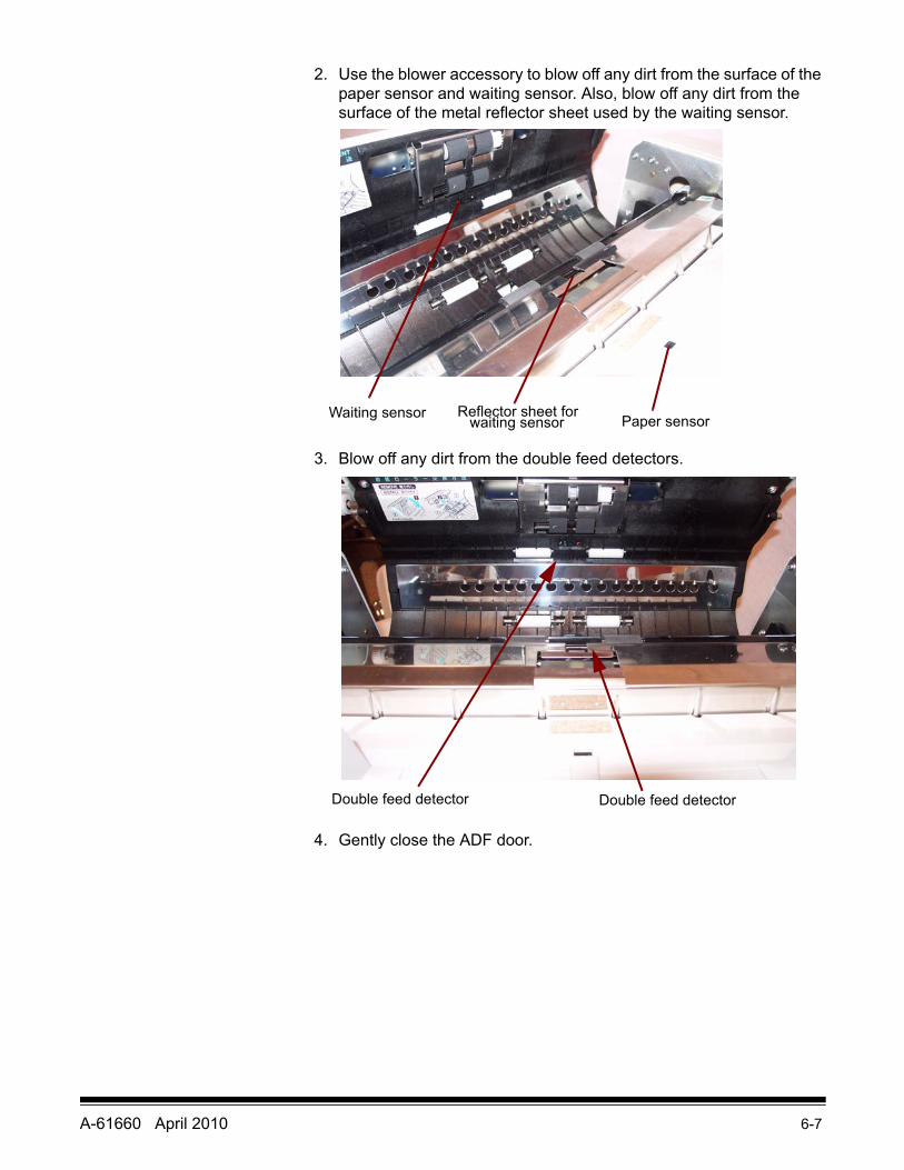
2. Use the blower accessory to blow off any dirt from the surface of the paper sensor and waiting sensor. Also, blow off any dirt from the surface of the metal reflector sheet used by the waiting sensor.
3. Blow off any dirt from the double feed detectors.
4. Gently close the ADF door.
Waiting sensor Reflector sheet forwaiting sensor Paper sensor
Double feed detector Double feed detector
6-8 A-61660 April 2010
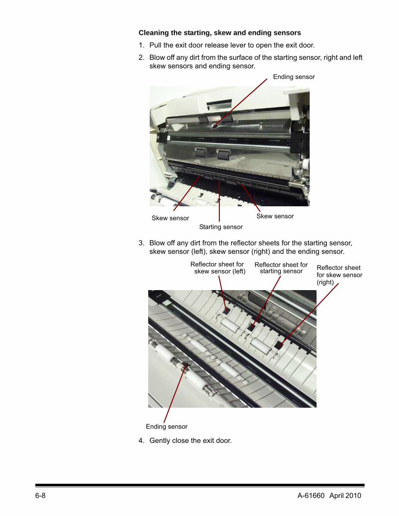
Cleaning the starting, skew and ending sensors1. Pull the exit door release lever to open the exit door.
2. Blow off any dirt from the surface of the starting sensor, right and left skew sensors and ending sensor.
3. Blow off any dirt from the reflector sheets for the starting sensor, skew sensor (left), skew sensor (right) and the ending sensor.
4. Gently close the exit door.
Ending sensor
Skew sensorStarting sensor
Skew sensor
Reflector sheet forskew sensor (left)
Reflector sheet forstarting sensor Reflector sheet
for skew sensor(right)
Ending sensor
A-61660 April 2010 6-9
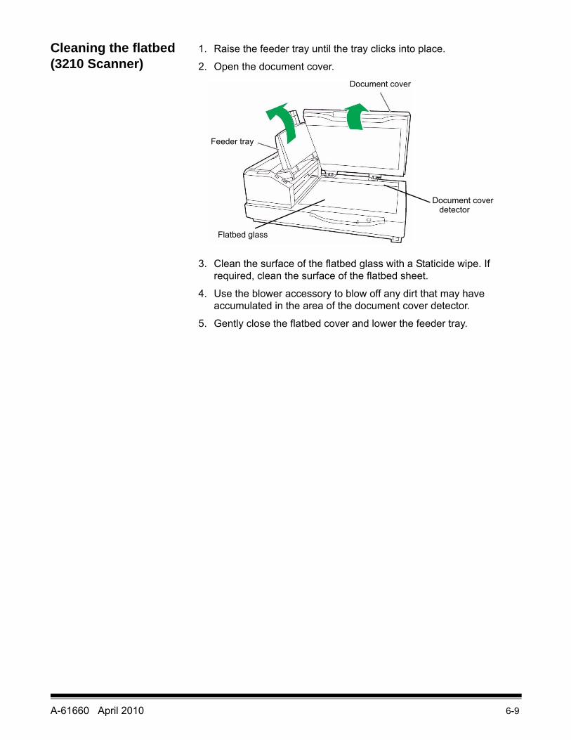
Cleaning the flatbed (3210 Scanner)
1. Raise the feeder tray until the tray clicks into place.
2. Open the document cover.
3. Clean the surface of the flatbed glass with a Staticide wipe. If required, clean the surface of the flatbed sheet.
4. Use the blower accessory to blow off any dirt that may have accumulated in the area of the document cover detector.
5. Gently close the flatbed cover and lower the feeder tray.
Document cover
Feeder tray
Document cover detector
Flatbed glass
6-10 A-61660 April 2010
Replacing Consumables
Replace the feed roller module and the separation roller module after 300,000 scans. Replace the roller modules more often if feeding problems continue after cleaning (i.e., paper jamming, slipping, multi-feeding, marking, etc.)
Replacing the paper feed roller module1. Turn the scanner off.
2. Push the ADF door release button to open the ADF door.
3. Open the Roller Exchange Kit. See “Supplies and consumables” later in this chapter for more information regarding additional Roller Exchange Kits.
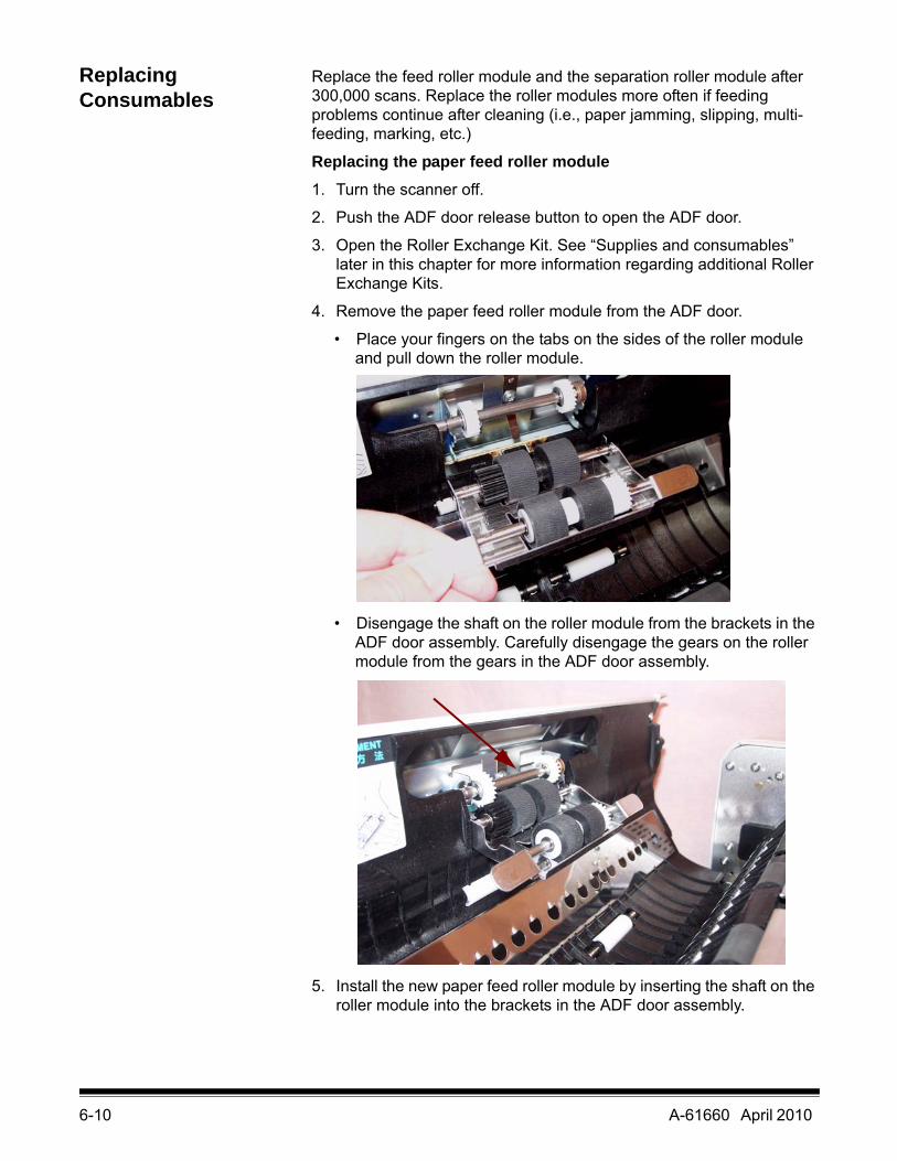
4. Remove the paper feed roller module from the ADF door.
• Place your fingers on the tabs on the sides of the roller module and pull down the roller module.
• Disengage the shaft on the roller module from the brackets in the ADF door assembly. Carefully disengage the gears on the roller module from the gears in the ADF door assembly.
5. Install the new paper feed roller module by inserting the shaft on the roller module into the brackets in the ADF door assembly.
A-61660 April 2010 6-11
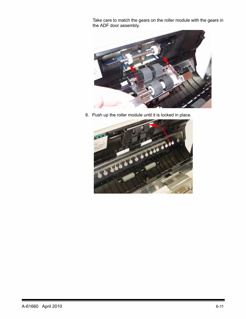
Take care to match the gears on the roller module with the gears in the ADF door assembly.
6. Push up the roller module until it is locked in place.
6-12 A-61660 April 2010
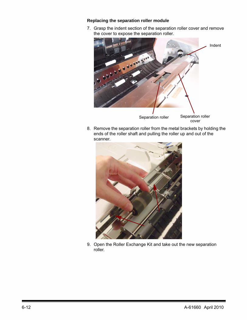
Replacing the separation roller module7. Grasp the indent section of the separation roller cover and remove
the cover to expose the separation roller.
8. Remove the separation roller from the metal brackets by holding the ends of the roller shaft and pulling the roller up and out of the scanner.
9. Open the Roller Exchange Kit and take out the new separation roller.
Separation roller Separation roller cover
Indent
A-61660 April 2010 6-13
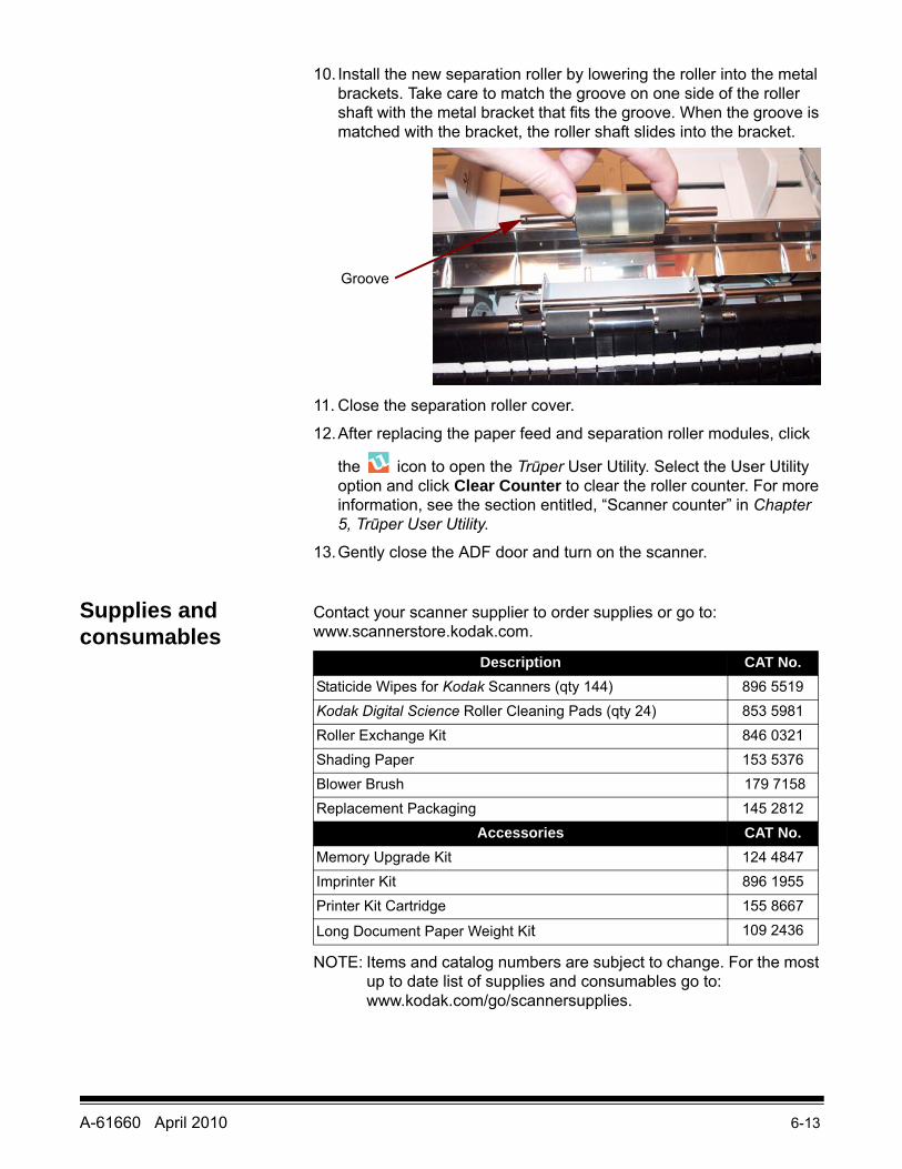
10. Install the new separation roller by lowering the roller into the metal brackets. Take care to match the groove on one side of the roller shaft with the metal bracket that fits the groove. When the groove is matched with the bracket, the roller shaft slides into the bracket.
11. Close the separation roller cover.
12.After replacing the paper feed and separation roller modules, click
the icon to open the Trūper User Utility. Select the User Utility option and click Clear Counter to clear the roller counter. For more information, see the section entitled, “Scanner counter” in Chapter 5, Trūper User Utility.
13.Gently close the ADF door and turn on the scanner.
Supplies and consumables
Contact your scanner supplier to order supplies or go to: www.scannerstore.kodak.com.
NOTE: Items and catalog numbers are subject to change. For the most up to date list of supplies and consumables go to: www.kodak.com/go/scannersupplies.
Groove
Description CAT No.Staticide Wipes for Kodak Scanners (qty 144) 896 5519Kodak Digital Science Roller Cleaning Pads (qty 24) 853 5981Roller Exchange Kit 846 0321Shading Paper 153 5376Blower Brush 179 7158Replacement Packaging 145 2812
Accessories CAT No.Memory Upgrade Kit 124 4847Imprinter Kit 896 1955Printer Kit Cartridge 155 8667
Long Document Paper Weight Kit 109 2436
A-61660 April 2010 7-1
7 Troubleshooting
Contents Clearing a document jam................................................................ 7-1Removing documents from the ADF area .................................. 7-1Removing documents from the exit area .................................... 7-2
Problem solving .............................................................................. 7-2User Utility error codes ................................................................... 7-4Scanner LED status ........................................................................ 7-5Contacting Service.......................................................................... 7-5
Clearing a document jam
Following are procedures for clearing an occasional document jam.
Removing documents from the ADF area
To minimize document jams, review the “Getting your documents ready to scan” in Chapter 3 for best feeder performance.
IMPORTANT: Only remove jammed documents from the ADF when the ADF door is open. Removing documents when the door is closed may damage the document.
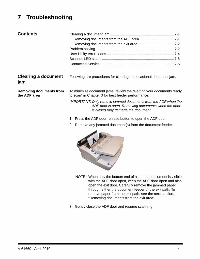
1. Press the ADF door release button to open the ADF door.
2. Remove any jammed document(s) from the document feeder.
NOTE: When only the bottom end of a jammed document is visible with the ADF door open, keep the ADF door open and also open the exit door. Carefully remove the jammed paper through either the document feeder or the exit path. To remove paper from the exit path, see the next section, “Removing documents from the exit area”.
3. Gently close the ADF door and resume scanning.
7-2 A-61660 April 2010
Removing documents from the exit area
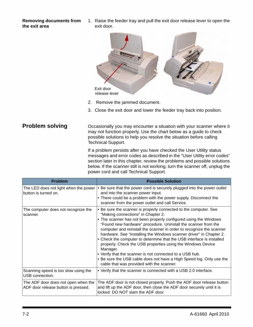
1. Raise the feeder tray and pull the exit door release lever to open the exit door.
2. Remove the jammed document.
3. Close the exit door and lower the feeder tray back into position.
Problem solving Occasionally you may encounter a situation with your scanner where it may not function properly. Use the chart below as a guide to check possible solutions to help you resolve the situation before calling Technical Support.
If a problem persists after you have checked the User Utility status messages and error codes as described in the “User Utility error codes” section later in this chapter, review the problems and possible solutions below. If the scanner still is not working, turn the scanner off, unplug the power cord and call Technical Support.
Exit doorrelease lever
Problem Possible SolutionThe LED does not light when the power button is turned on.
• Be sure that the power cord is securely plugged into the power outlet and into the scanner power input.
• There could be a problem with the power supply. Disconnect the scanner from the power outlet and call Service.
The computer does not recognize the scanner.
• Be sure the scanner is properly connected to the computer. See “Making connections” in Chapter 2.
• The scanner has not been properly configured using the Windows “Found new hardware” procedure. Uninstall the scanner from the computer and reinstall the scanner in order to recognize the scanner hardware. See “Installing the Windows scanner driver” in Chapter 2.
• Check the computer to determine that the USB interface is installed properly. Check the USB properties using the Windows Device Manager.
• Verify that the scanner is not connected to a USB hub.• Be sure the USB cable does not have a High Speed log. Only use the
cable that was provided with the scanner. Scanning speed is too slow using the USB connection.
• Verify that the scanner is connected with a USB 2.0 interface.
The ADF door does not open when the ADF door release button is pressed.
The ADF door is not closed properly. Push the ADF door release button and lift up the ADF door, then close the ADF door securely until it is locked. DO NOT slam the ADF door.
A-61660 April 2010 7-3
Problem Possible Solution(ADF) The document has been loaded on the feeder tray, but the scanner does not start scanning.
• The document is not loaded properly. See the section entitled, “Scanning documents” in Chapter 3.
• The sensor cannot detect the document because the edge of the document is curled. Flatten the document and load it again. See the section entitled, “Getting your documents ready to scan” in Chapter 3.
(ADF) Double feeding or skewing problems occur frequently or the scanner stops feeding while scanning.
• The rollers may be dirty or have reached their life expectancy. Clean the rollers and examine them for wear. See Chapter 6, Maintenance for cleaning and replacement procedures.
• The document is curled for folded. Flatten the document, reduce the number of sheets in the feeder tray and load the document again.
(ADF) Scanned image is skewed. • Be sure the document guides are adjusted to the size of the documents being scanned.
• Verify that the document to be scanned is straight in the feeder tray.• The right and left sides of the document to be scanned are not the
same height because of curls and folds. Remove the curls or folds, reduce the number of sheets in the feeder tray and load the document again.
For 3210 Scanner only:• An irregular type of document needs to be scanned. Use the flatbed to
scan the document.• The document length is less than 2.75 in (70 mm). Use the flatbed to
scan the document.(ADF) The scanned document is blank. Verify that the document to be scanned is positioned correctly in the
feeder tray. Documents should be placed in the feeder tray face-up.Vertical lines appear on the scanned document.
Clean the imaging guides (or flatbed glass) and background bars. See Chapter 6, Maintenance for cleaning procedures.
The scanning density is uneven. • Clean the imaging guides (or flatbed glass) and background bars. See Chapter 6, Maintenance for cleaning procedures.
• Perform a shading adjustment. See Chapter 5, User Utility (User Shading) for more information.
The color of the scanned document is very different from the original document.
Adjust the computer display and monitor settings.
Dark spots or noise appear on the scanned documents.
Clean the imaging guides (or flatbed glass) and background bars. See Chapter 6, Maintenance for cleaning procedures.
Scanned image has moire fringes or patterns, such as stripes or wavy pattern noise.
This is caused by the original printing pattern on the document and the selected scanning resolution. Change the scanning resolution, then scan the document(s) again.
Image crop failures with VRS scanning. Paper or dust may be on the background bars. Examine and clean the background bars. See Chapter 6, Maintenance for cleaning procedures.
7-4 A-61660 April 2010
User Utility error codes
If an issue occurs during scanning, click the icon to open the Trūper User Utility. Check the Scanner Status message and Error Code information. The following table explains the error codes and messages and describes possible causes/solutions.
Error code and message Possible Cause/SolutionU11, U12, U13, U14, U15, U16, U17Jam occurred. Please open the door and remove the paper.
A document is jammed or the document sensors are dirty.• Open the ADF and exit doors and remove the jammed paper. See “Clearing a
document jam” earlier in this chapter.• Clean the sensors. See Chapter 6, Maintenance for cleaning procedures.
U18Document remains in the scanner. Please open the door and remove the paper.
A document is jammed or the document sensors are dirty.• Open the ADF and exit doors and remove the jammed paper. See “Clearing a
document jam” earlier in this chapter.• Clean the sensors. See Chapter 6, Maintenance for cleaning procedures.
U20Skew error occurred.
• Open the ADF and exit doors and remove the jammed paper. See “Clearing a document jam” earlier in this chapter.
U23Double feed occurred. Please open the door and remove the paper.
A double feed has occurred or the rollers are dirty.• Open the ADF and exit doors and remove the jammed paper. See “Clearing a
document jam” earlier in this chapter.• Clean the rollers. See Chapter 6, Maintenance for cleaning procedures.
U30, U32, U34Scanner door is open. Please close the door.
• Securely close the ADF door.
FxxSystem error occurred. Please contact Technical Support.
• Contact Technical Support.
***Warning***The rollers need to be cleaned. Please clean the rollers. Please select the Clear Counter button after cleaning the rollers.
Warning counter has expiredThe rollers need to be cleaned.• Clean the rollers. See Chapter 6, Maintenance for cleaning procedures. After
cleaning the rollers, return to the User Utility and click the Clear Counter button. See the section entitled, “The User Utility dialog box“ (Scanner Counter) in Chapter 5.
***Warning***The rollers need to be replaced. Please replace the rollers.Please select Clear Counter button after replacing the rollers
Warning counter has expiredThe rollers need to be replaced.• Replace the rollers. See Chapter 6, Maintenance for replacement procedures.
After replacing the rollers, return to the User Utility and click the Clear Counter button. See the section entitled, “The User Utility dialog box“ (Scanner Counter) in Chapter 5.
*** Warning ***Insufficient front light error occurred.The lamp and/or scanning sensor need to be replaced.
It is time to replace the lamp and scanning sensor (front).• Contact Technical Support.
*** Warning ***Insufficient back light error occurred.The lamp and/or scanning sensor need to be replaced
It is time to replace the lamp and scanning sensor (back).• Contact Technical Support.
A-61660 April 2010 7-5
Scanner LED status The color of the LED indicates the scanner status.
Contacting Service 1. Visit www.Kodak.com/go/dicontacts to obtain the most current phone number for your country.
2. When calling, please have the following information ready:
• A description of your problem.
• The scanner model and serial number.
• Computer configuration.
• Software application you are using.
Error code and message Possible Cause/Remedy*** Warning ***The front reference plate may need to be cleaned.Please clean the front reference plate
The upper background bar is dirty.• Clean the upper background bar. See Chapter 6, Maintenance for cleaning
procedures.
*** Warning ***The back reference plate may need to be cleaned.Please clean the back reference plate.
The lower background bar is dirty.Clean the lower background bar. See Chapter 6, Maintenance for cleaning procedures.
Scanner is not connected. • If the scanner is not connected, connect the scanner to the computer, turn on the scanner and restart the computer.
• If the scanner is not turned on, turn the scanner on and then restart the computer.
• If the computer was turned on before the scanner was ready, restart the computer.
LED StatusSteady green Ready to scan or scanning is in process.Flashing green Sleep mode.Flashing green/orange Multifeed Ignore function is set.Steady orange The rollers need to be cleaned or replaced.
Scanning can continue.Flashing orange Initializing or Sleep mode with warning. Check
the status of the scanner using the User Utility.Red An error occurred. Check the status of the
scanner using the User Utility.
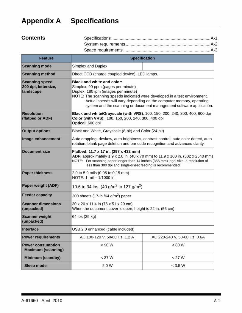
A-61660 April 2010 A-1
Appendix A Specifications
Contents Specifications ..................................................................................A-1System requirements ......................................................................A-2Space requirements ........................................................................A-3
Feature Specification
Scanning mode Simplex and Duplex
Scanning method Direct CCD (charge coupled device). LED lamps.
Scanning speed200 dpi, lettersize, landscape
Black and white and color:Simplex: 90 ppm (pages per minute)Duplex; 180 ipm (images per minute)NOTE: The scanning speeds indicated were developed in a test environment.
Actual speeds will vary depending on the computer memory, operating system and the scanning or document management software application.
Resolution(flatbed or ADF)
Black and white/Grayscale (with VRS): 100, 150, 200, 240, 300, 400, 600 dpi Color (with VRS): 100, 150, 200, 240, 300, 400 dpiOptical: 600 dpi
Output options Black and White, Grayscale (8-bit) and Color (24-bit)
Image enhancement Auto cropping, deskew, auto brightness, contrast control, auto color detect, auto rotation, blank page deletion and bar code recognition and advanced clarity.
Document size Flatbed: 11.7 x 17 in. (297 x 432 mm)ADF: approximately 1.9 x 2.8 in. (48 x 70 mm) to 11.9 x 100 in. (302 x 2540 mm)NOTE: For scanning paper longer than 14 inches (356 mm) legal size, a resolution of
less than 300 dpi and single-sheet feeding is recommended.
Paper thickness 2.0 to 5.9 mils (0.05 to 0.15 mm)NOTE: 1 mil = 1/1000 in.
Paper weight (ADF) 10.6 to 34 lbs. (40 g/m2 to 127 g/m2)
Feeder capacity 200 sheets (17-lb./64 g/m2) paper
Scanner dimensions(unpacked)
30 x 20 x 11.4 in (76 x 51 x 29 cm)When the document cover is open, height is 22 in. (56 cm)
Scanner weight(unpacked)
64 lbs (29 kg)
Interface USB 2.0 enhanced (cable included)
Power requirements AC 100-120 V, 50/60 Hz, 1.2 A AC 220-240 V, 50-60 Hz, 0.6A
Power consumption Maximum (scanning)
< 90 W < 80 W
Minimum (standby) < 27 W < 27 W
Sleep mode 2.0 W < 3.5 W
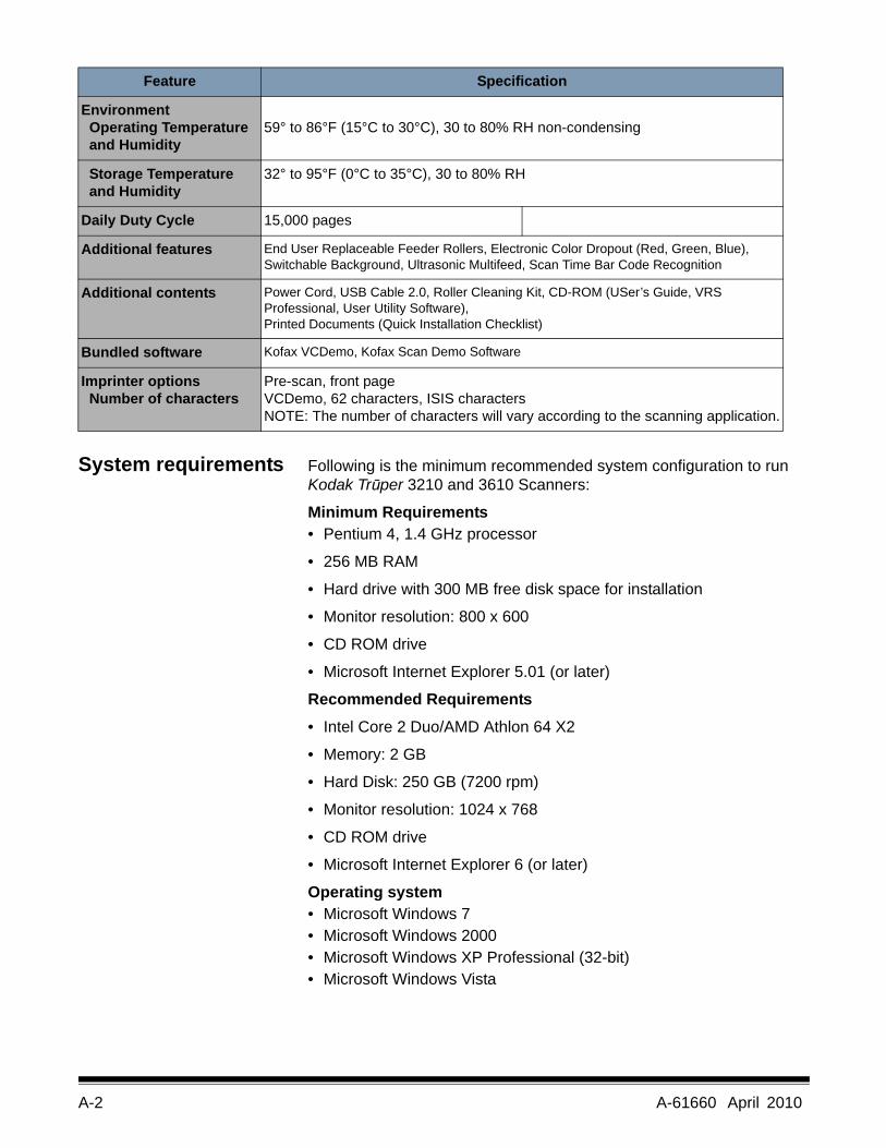
A-2 A-61660 April 2010
System requirements Following is the minimum recommended system configuration to run Kodak Trūper 3210 and 3610 Scanners:
Minimum Requirements• Pentium 4, 1.4 GHz processor
• 256 MB RAM
• Hard drive with 300 MB free disk space for installation
• Monitor resolution: 800 x 600
• CD ROM drive
• Microsoft Internet Explorer 5.01 (or later)
Recommended Requirements• Intel Core 2 Duo/AMD Athlon 64 X2
• Memory: 2 GB
• Hard Disk: 250 GB (7200 rpm)
• Monitor resolution: 1024 x 768
• CD ROM drive
• Microsoft Internet Explorer 6 (or later)
Operating system• Microsoft Windows 7• Microsoft Windows 2000 • Microsoft Windows XP Professional (32-bit)• Microsoft Windows Vista
Feature Specification
Environment Operating Temperature and Humidity
59° to 86°F (15°C to 30°C), 30 to 80% RH non-condensing
Storage Temperature and Humidity
32° to 95°F (0°C to 35°C), 30 to 80% RH
Daily Duty Cycle 15,000 pages
Additional features End User Replaceable Feeder Rollers, Electronic Color Dropout (Red, Green, Blue), Switchable Background, Ultrasonic Multifeed, Scan Time Bar Code Recognition
Additional contents Power Cord, USB Cable 2.0, Roller Cleaning Kit, CD-ROM (USer’s Guide, VRS Professional, User Utility Software), Printed Documents (Quick Installation Checklist)
Bundled software Kofax VCDemo, Kofax Scan Demo Software
Imprinter options Number of characters
Pre-scan, front pageVCDemo, 62 characters, ISIS charactersNOTE: The number of characters will vary according to the scanning application.
A-61660 April 2010 A-3
Display: Resolution 1024 x 768 or more; 65,536 colors or more
Interface: USB 2.0 (enhanced)
NOTES:• Do not connect the scanner to a USB hub.
• There must be 1 GB or more of free space on the hard drive.
• Depending on the computer system and the scanning application or document management software used, you may not be able to scan a large color image in high resolution.
Space requirements Following are the minimum space requirements that are recommended to open and maintain the scanner. The recommended clearance of the top and sides of the scanner will ensure that there is proper ventilation and provide the necessary area for scanner maintenance.
• Top clearance necessary to open the document cover: 27.6 in. (700 mm)
• Sides: 7.9 in. (200 mm)
• Front clearance necessary to pull the exit stopped forward: 11.8i in. (300 mm)
• Rear clearance necessary to remove or install the computer interface board: 13.8 in. (350 mm)
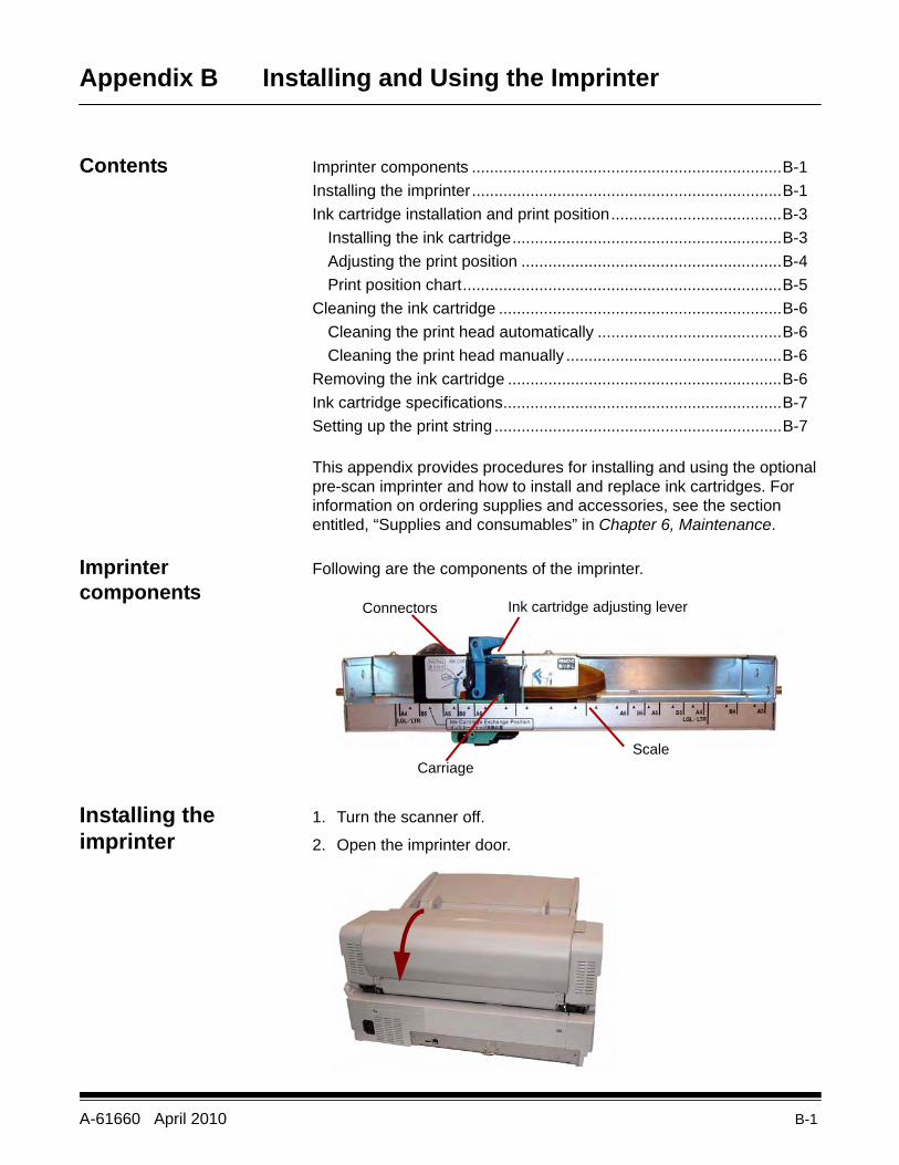
A-61660 April 2010 B-1
Appendix B Installing and Using the Imprinter
Contents Imprinter components .....................................................................B-1Installing the imprinter.....................................................................B-1Ink cartridge installation and print position......................................B-3
Installing the ink cartridge............................................................B-3Adjusting the print position ..........................................................B-4Print position chart.......................................................................B-5
Cleaning the ink cartridge ...............................................................B-6Cleaning the print head automatically .........................................B-6Cleaning the print head manually ................................................B-6
Removing the ink cartridge .............................................................B-6Ink cartridge specifications..............................................................B-7Setting up the print string ................................................................B-7
This appendix provides procedures for installing and using the optional pre-scan imprinter and how to install and replace ink cartridges. For information on ordering supplies and accessories, see the section entitled, “Supplies and consumables” in Chapter 6, Maintenance.
Imprinter components
Following are the components of the imprinter.
Installing the imprinter
1. Turn the scanner off.
2. Open the imprinter door.
Connectors Ink cartridge adjusting lever
ScaleCarriage
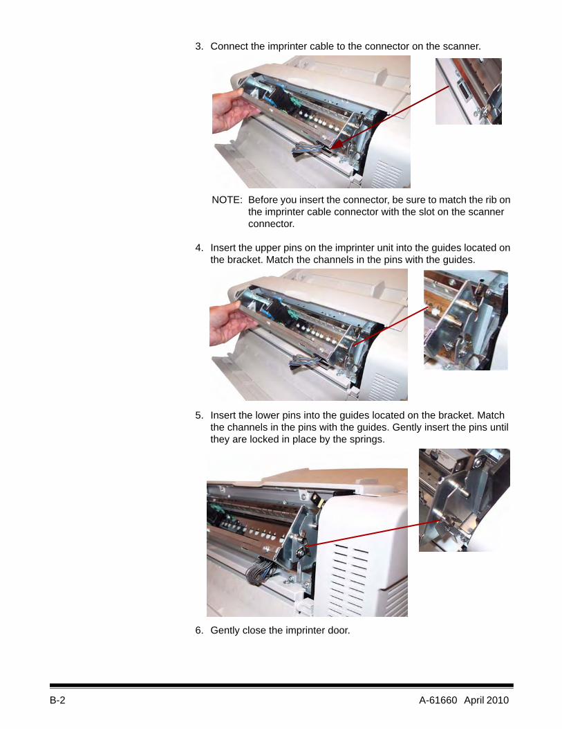
B-2 A-61660 April 2010
3. Connect the imprinter cable to the connector on the scanner.
NOTE: Before you insert the connector, be sure to match the rib on the imprinter cable connector with the slot on the scanner connector.
4. Insert the upper pins on the imprinter unit into the guides located on the bracket. Match the channels in the pins with the guides.
5. Insert the lower pins into the guides located on the bracket. Match the channels in the pins with the guides. Gently insert the pins until they are locked in place by the springs.
6. Gently close the imprinter door.
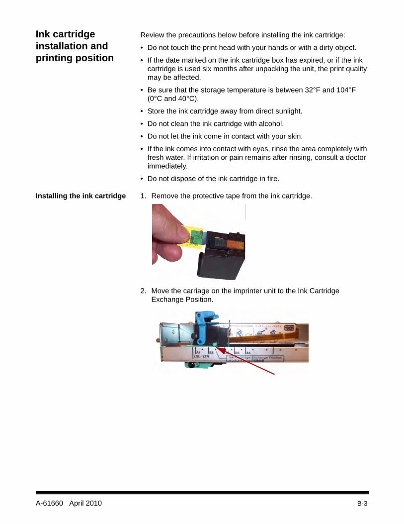
A-61660 April 2010 B-3
Ink cartridge installation and printing position
Review the precautions below before installing the ink cartridge:
• Do not touch the print head with your hands or with a dirty object.
• If the date marked on the ink cartridge box has expired, or if the ink cartridge is used six months after unpacking the unit, the print quality may be affected.
• Be sure that the storage temperature is between 32°F and 104°F (0°C and 40°C).
• Store the ink cartridge away from direct sunlight.
• Do not clean the ink cartridge with alcohol.
• Do not let the ink come in contact with your skin.
• If the ink comes into contact with eyes, rinse the area completely with fresh water. If irritation or pain remains after rinsing, consult a doctor immediately.
• Do not dispose of the ink cartridge in fire.
Installing the ink cartridge 1. Remove the protective tape from the ink cartridge.
2. Move the carriage on the imprinter unit to the Ink Cartridge Exchange Position.
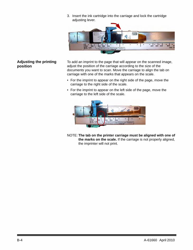
B-4 A-61660 April 2010
3. Insert the ink cartridge into the carriage and lock the cartridge adjusting lever.
Adjusting the printing position
To add an imprint to the page that will appear on the scanned image, adjust the position of the carriage according to the size of the documents you want to scan. Move the carriage to align the tab on carriage with one of the marks that appears on the scale.
• For the imprint to appear on the right side of the page, move the carriage to the right side of the scale.
• For the imprint to appear on the left side of the page, move the carriage to the left side of the scale.
NOTE: The tab on the printer carriage must be aligned with one of the marks on the scale. If the carriage is not properly aligned, the imprinter will not print.
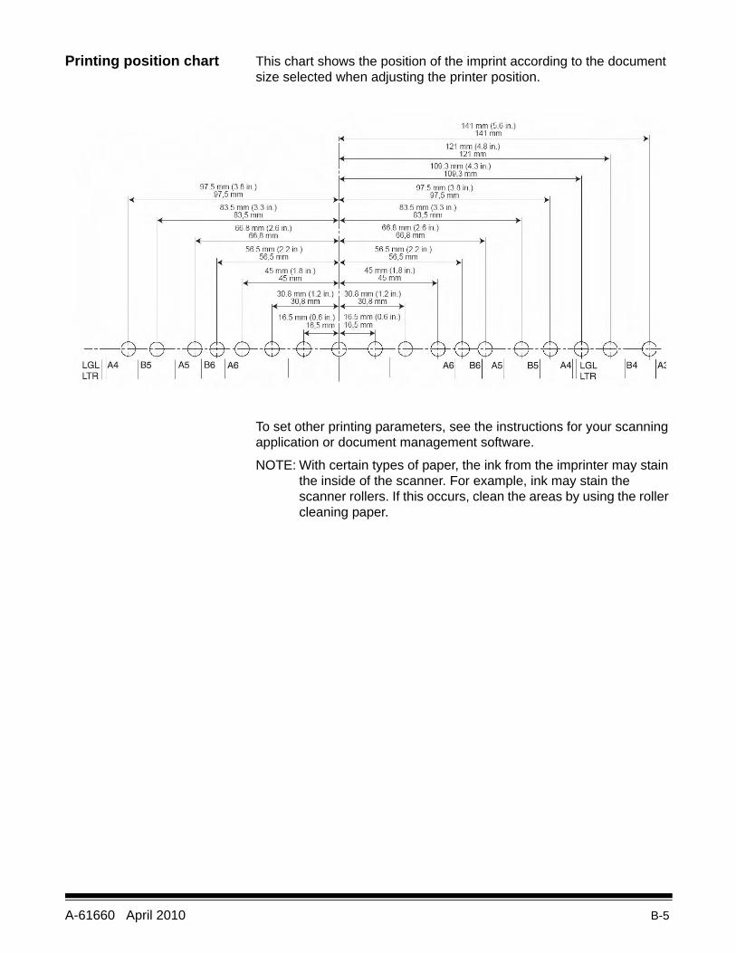
A-61660 April 2010 B-5
Printing position chart This chart shows the position of the imprint according to the document size selected when adjusting the printer position.
To set other printing parameters, see the instructions for your scanning application or document management software.
NOTE: With certain types of paper, the ink from the imprinter may stain the inside of the scanner. For example, ink may stain the scanner rollers. If this occurs, clean the areas by using the roller cleaning paper.
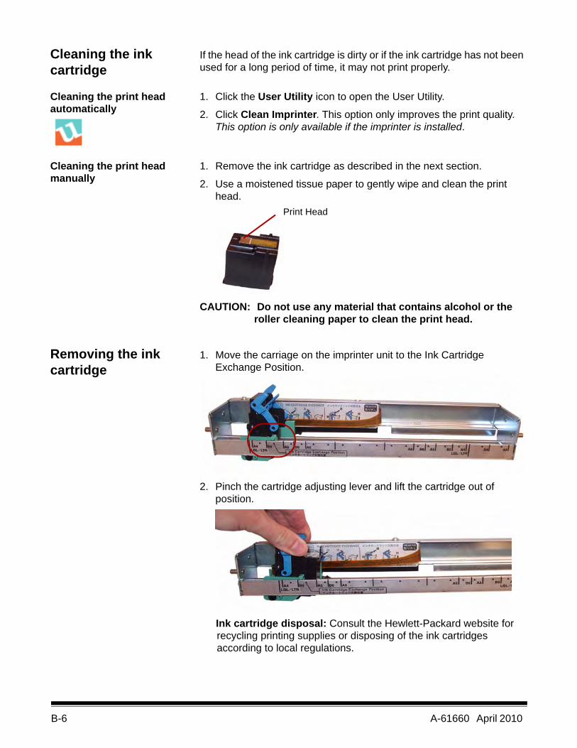
B-6 A-61660 April 2010
Cleaning the ink cartridge
If the head of the ink cartridge is dirty or if the ink cartridge has not been used for a long period of time, it may not print properly.
Cleaning the print head automatically
1. Click the User Utility icon to open the User Utility.
2. Click Clean Imprinter. This option only improves the print quality. This option is only available if the imprinter is installed.
Cleaning the print head manually
1. Remove the ink cartridge as described in the next section.
2. Use a moistened tissue paper to gently wipe and clean the print head.
CAUTION: Do not use any material that contains alcohol or the roller cleaning paper to clean the print head.
Removing the ink cartridge
1. Move the carriage on the imprinter unit to the Ink Cartridge Exchange Position.
2. Pinch the cartridge adjusting lever and lift the cartridge out of position.
Ink cartridge disposal: Consult the Hewlett-Packard website for recycling printing supplies or disposing of the ink cartridges according to local regulations.
Print Head
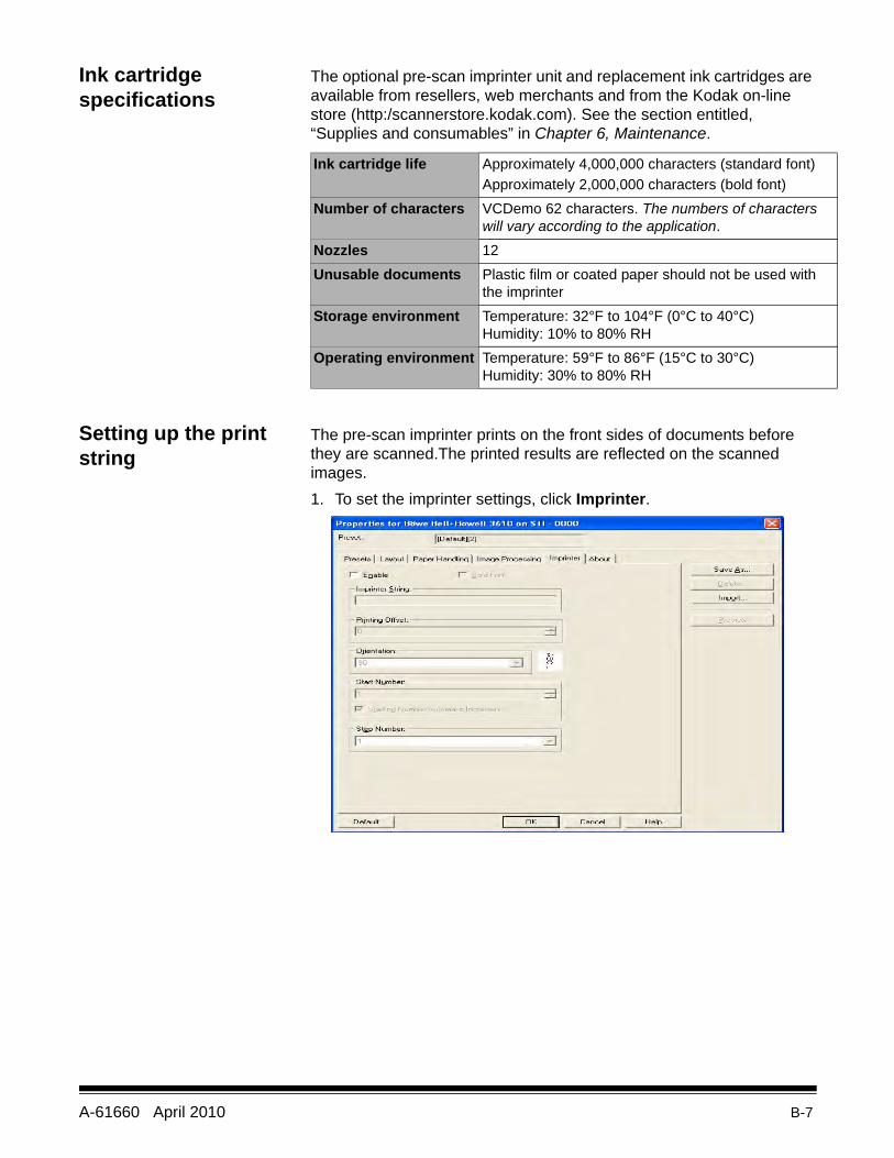
A-61660 April 2010 B-7
Ink cartridge specifications
The optional pre-scan imprinter unit and replacement ink cartridges are available from resellers, web merchants and from the Kodak on-line store (http:/scannerstore.kodak.com). See the section entitled, “Supplies and consumables” in Chapter 6, Maintenance.
Setting up the print string
The pre-scan imprinter prints on the front sides of documents before they are scanned.The printed results are reflected on the scanned images.1. To set the imprinter settings, click Imprinter.
Ink cartridge life Approximately 4,000,000 characters (standard font)Approximately 2,000,000 characters (bold font)
Number of characters VCDemo 62 characters. The numbers of characters will vary according to the application.
Nozzles 12Unusable documents Plastic film or coated paper should not be used with
the imprinterStorage environment Temperature: 32°F to 104°F (0°C to 40°C)
Humidity: 10% to 80% RHOperating environment Temperature: 59°F to 86°F (15°C to 30°C)
Humidity: 30% to 80% RH
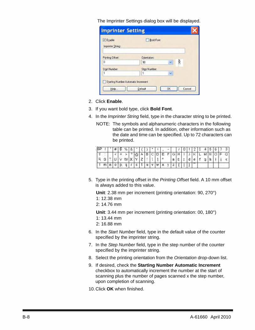
B-8 A-61660 April 2010
The Imprinter Settings dialog box will be displayed.
2. Click Enable.3. If you want bold type, click Bold Font.4. In the Imprinter String field, type in the character string to be printed.
NOTE: The symbols and alphanumeric characters in the following table can be printed. In addition, other information such as the date and time can be specified. Up to 72 characters can be printed.
5. Type in the printing offset in the Printing Offset field. A 10 mm offset is always added to this value.Unit: 2.38 mm per increment (printing orientation: 90, 270°) 1: 12.38 mm2: 14.76 mm
Unit: 3.44 mm per increment (printing orientation: 00, 180°)1: 13.44 mm2: 16.88 mm
6. In the Start Number field, type in the default value of the counter specified by the imprinter string.
7. In the Step Number field, type in the step number of the counter specified by the imprinter string.
8. Select the printing orientation from the Orientation drop-down list.9. If desired, check the Starting Number Automatic Increment
checkbox to automatically increment the number at the start of scanning plus the number of pages scanned x the step number, upon completion of scanning.
10.Click OK when finished.
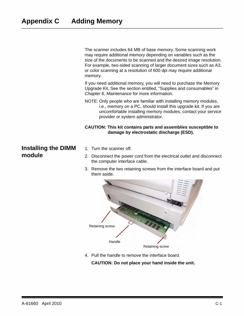
A-61660 April 2010 C-1
Appendix C Adding Memory
The scanner includes 64 MB of base memory. Some scanning work may require additional memory depending on variables such as the size of the documents to be scanned and the desired image resolution. For example, two-sided scanning of larger document sizes such as A3, or color scanning at a resolution of 600 dpi may require additional memory.
If you need additional memory, you will need to purchase the Memory Upgrade Kit. See the section entitled, “Supplies and consumables” in Chapter 6, Maintenance for more information.
NOTE: Only people who are familiar with installing memory modules, i.e., memory on a PC, should install this upgrade kit. If you are uncomfortable installing memory modules, contact your service provider or system administrator.
CAUTION: This kit contains parts and assemblies susceptible to damage by electrostatic discharge (ESD).
Installing the DIMM module
1. Turn the scanner off.
2. Disconnect the power cord from the electrical outlet and disconnect the computer interface cable.
3. Remove the two retaining screws from the interface board and put them aside.
4. Pull the handle to remove the interface board.
CAUTION: Do not place your hand inside the unit.
Retaining screw
Retaining screw
Handle
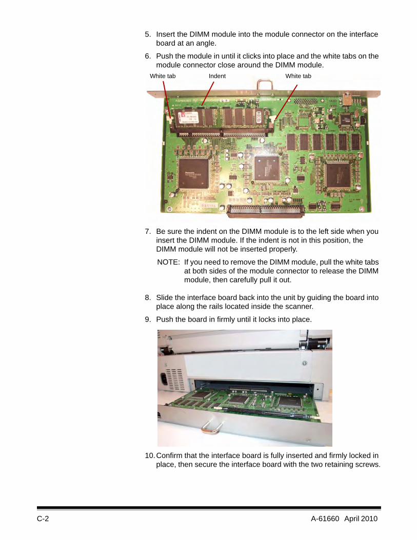
C-2 A-61660 April 2010
5. Insert the DIMM module into the module connector on the interface board at an angle.
6. Push the module in until it clicks into place and the white tabs on the module connector close around the DIMM module.
7. Be sure the indent on the DIMM module is to the left side when you insert the DIMM module. If the indent is not in this position, the DIMM module will not be inserted properly.
NOTE: If you need to remove the DIMM module, pull the white tabs at both sides of the module connector to release the DIMM module, then carefully pull it out.
8. Slide the interface board back into the unit by guiding the board into place along the rails located inside the scanner.
9. Push the board in firmly until it locks into place.
10.Confirm that the interface board is fully inserted and firmly locked in place, then secure the interface board with the two retaining screws.
White tabIndentWhite tab
A-61660 April 2010 D-1
Appendix D Glossary
Automatic Document Feed (ADF) mode — the scanner mode in which the documents are automatically fed, rather than manually fed, into the document feeder.
Crop (auto crop) — this software option automatically crops every page to its original size by looking for page or document borders.
Deskew — the process of electronically straightening an image after it has been scanned. This can be done through software or through firmware on the scanner.
Double Feed — occurs when more than one document is fed through the feeder at one time.
Duplex scanner — a scanner capable of scanning both sides of a document in a single pass through the scanner.
Error message — a message displayed in the User Utility dialog box, or an indicator light on the LED status indicator. Error messages or indicators appear whenever the scanner determines that a problem exists.
Flatbed sheet — adjustable component used in conjunction with the reference plates to change the background color of the scanned documents.
Imprinter — optional accessory that allows for front page pre-scan imprinting of a string of alphanumeric characters on documents that are fed into the scanner transport.
Manual mode — the scanner mode in which documents are manually fed by the operator, rather than automatically fed into the feeder.
Multi color dropout — allows you to dropout up to 6 colors from a color document when scanning in black and white mode.
Paper path — the curved path taken by a document as it passes through the scanner.
Paper transport — the mechanical system for moving a document through the scanner.
Resolution — a measurement of the ability of a scanner to reproduce small objects. The higher the resolution, the smaller the object the scanner can reproduce. Resolution is measured in dots per inch (dpi).
RGB — three components of color: Red, Green, Blue.
Simplex scanner — a scanner designed to scan one side of a document as it passes through the scanner.
Single color dropout — allows you to dropout one color (red, green or blue) from a color document when scanning in black and white mode.
D-2 A-61660 April 2010
Skew — the result of feeding a document at an angle. It appears crooked or misaligned on the display and also looks this way when printed. To minimize skew, guide the document against the left document feed guide.
Transport system. See Paper transport.
USB (Universal Serial Bus) — a data transmission system that operates between the scanner and the host computer system.
VRS (VirtualReScan) — VRS is an electronic check-point for scanned images. As images pass through the scanner, VRS performs a multi-point inspection of each document. VRS automatically checks and adjusts for alignment (skew), brightness, contrast and image clarity.
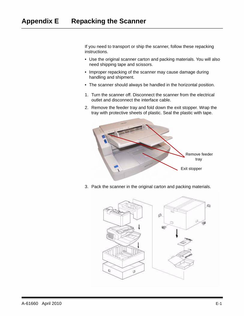
A-61660 April 2010 E-1
Appendix E Repacking the Scanner
If you need to transport or ship the scanner, follow these repacking instructions.
• Use the original scanner carton and packing materials. You will also need shipping tape and scissors.
• Improper repacking of the scanner may cause damage during handling and shipment.
• The scanner should always be handled in the horizontal position.
1. Turn the scanner off. Disconnect the scanner from the electrical outlet and disconnect the interface cable.
2. Remove the feeder tray and fold down the exit stopper. Wrap the tray with protective sheets of plastic. Seal the plastic with tape.
3. Pack the scanner in the original carton and packing materials.
Remove feeder tray
Exit stopper

User’s Guide
Eastman Kodak Company343 State StreetRochester, NY 14650 U.S.A.© Kodak, 2010. All rights reserved. TM: Kodak, Truper
6J7207A
CYAN MAGENTA YELLOW BLACKCYAN
8.5 x 11” Folded
GUIDE COVER-KODAK SCANNERS
FONTS
Whitney K Family
SIZE P/N SWATCHES
FILE FORMAT
DESIGN/IMPLEMENTATION
DATE12.22.09
6J7207A
DE MEYER
4 COLOR PROCESS
ARTWORK NAME
PRINTING INFORMATION
0000-000ECO LANGUAGES
ILLUSTRATOR CS3
EN
A-616606J7207
Truper3210 Scanner3610 Scanner
¯