Embed Size (px)
Citation preview
A 50-Gallon Pilot Plant Fermentor for Classroom Instruction1
G. J. FULD AND C. G. DUNN
Department of Food Technology, Massachusetts Institute of Technology, Cambridge, Ma8sachusett8
Received for publication June 12, 1957
Various types of pilot plant and laboratory-sizesubmerged culture fermentors have been describedrecently. Most of the laboratory-size fermentors of 5-to 30-L capacity consist either of large Pyrex jars or ofstainless steel containers, equipped with metal coversand devices for securing them. The accessories, suchas agitators, aerators, air outlets, sampling cocks, andbaffles, are fitted to the cover. The assembly is placedgenerally in a constant temperature bath. Fermentorsof this general description have been described byBartholomew et al. (1950), Rivett et al. (1950), Brownand Peterson (1950), Chain et al. (1954a), Friedlandet al. (1956), and others.
Fermentors of a larger pilot plant size (50 L to 2000gallons) have been described to a more limited extent,and generally resemble plant-scale equipment moreclosely than the smaller laboratory-scale models.Stefaniak et al. (1946) reported on a 100-gallon fermen-tor, and Gordon et al. (1947) described, in somewhatmore detail, a 50-gallon, glass-lined fermentor assembly.Pfeifer et al. (1952) and Blom et al. (1952) reported on abattery of 80-, 300-, and 600-gallon pilot plant fer-mentors. Dworschack et at. (1954) described a batteryof 20-L fermentors that closely resemble the plant-scaleequipment and which possessed quite a few interestingdetails. The most comprehensive description of pilotplant equipment that is available is undoubtedly theseries of articles by Chain and his co-workers (1954b).Paladino et al. (1954) provided complete details of 90-and 300-L fermentation units. Several photographs andseveral dozen detailed working-drawings were pre-sented. The entire layout of the pilot plant equipmentwas outlined by Chain et at. (1954b) which consistedof several dozen 90- and 300-L fermentors, a full batteryof 10-L fermentors, incubators, a cold storage room, acomplete preparation room (with extractors, filters andso forth), a solvent recovery plant, and several largeautoclaves. The most recent paper on large-scale equip-ment was that of Kroll et al. (1956) which described50-L top-mounted tanks with unique teflon-packedstuffing boxes for the agitator. A novel sight-glass andadditive reservoir system were included. Nelson et al.(1956) described a 20-L fermentor with many controlfeatures including a torsion dynamometer for power
1 Contribution No. 329 from the Department of FoodTechnology.
measurements, an oxygen and carbon dioxide analyzer,and a pH recorder.
DESCRIPTION OF THE FERMENTOR
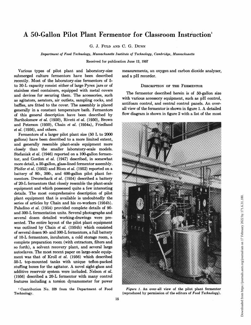
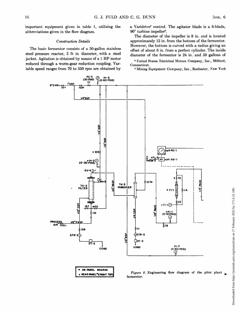
The fermentor described herein is of 50-gallon sizewith various accessory equipment, such as pH control,antifoam control, and central control panels. An over-all view of the fermentor is shown in figure 1. A detailedflow diagram is shown in figure 2 with a list of the most
Figure 1. An over-all view of the pilot plant fermentor(reproduced by permission of the editors of Food Technology).
15
Dow
nloa
ded
from
http
s://j
ourn
als.
asm
.org
/jour
nal/a
m o
n 17
Feb
ruar
y 20
22 b
y 17
1.6.
31.1
80.
G. J. FULD AND C. G. DUNN
important equipment given in table 1, utilizing theabbreviations given in the flow diagram.
Construction Details
The basic fermentor consists of a 50-gallon stainlesssteel pressure reactor, 2 ft in diameter, with a steeljacket. Agitation is obtained by means of a 1 HP motorreduced through a worm-gear reduction coupling. Var-iable speed ranges from 70 to 350 rpm are obtained by
a Varidrive2 control. The agitator blade is a 6-blade,900 turbine impeller3.The diameter of the impeller is 8 in. and is located
approximately 12 in. from the bottom of the fermentor.However, the bottom is curved with a radius giving an
offset of about 6 in. from a perfect cylinder. The insidediameter of the fermentor is 24 in. and 50 gallons of
2 United States Electrical Motors Company, Inc., Milford,Connecticut.
3 Mixing Equipment Coirpany, Inc., Rochester, New York
PC-3 PSIG(30 PSIG) ~(0.60 PSIG)
-pH RC- I
L'P -3o -E, *pH AM-1I
Figure 2. Engineering flow diagram of the pilot plant >fermentor.
* ON PANEL BOARDSNEAR MNEL*I(RIGHT TOP)
16 [VOL. 6
Dow
nloa
ded
from
http
s://j
ourn
als.
asm
.org
/jour
nal/a
m o
n 17
Feb
ruar
y 20
22 b
y 17
1.6.
31.1
80.
PILOT PLANT FERMENTOR FOR CLASSROOM
medium gives a level inside the fermentor of approxi-mately 20 in. The aeration tube outlet is located 2 in.below the impeller and consists of an open / in. stain-less steel pipe. The baffles consist of four strips of stain-less steel, each 2 in. wide and mounted vertically 900apart. The stuffing box consists of a lantern bearing ofBost-Bronze4 and nontoxic asbestos packing5. The unitis held in place with an adjustable tension fitting. A
Boston Gear Works, Boston, Massachusetts.6 Johns-Manville, New York, New York.
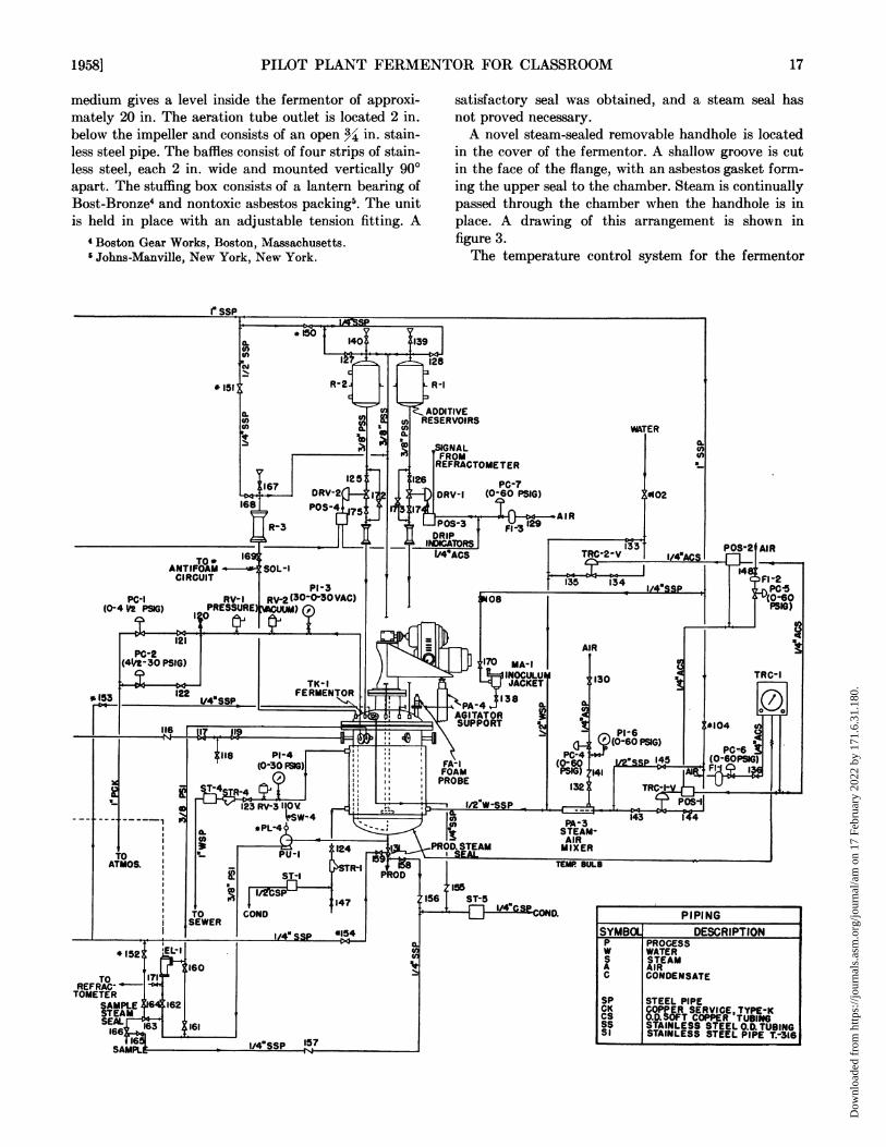
satisfactory seal was obtained, and a steam seal hasnot proved necessary.A novel steam-sealed removable handhole is located
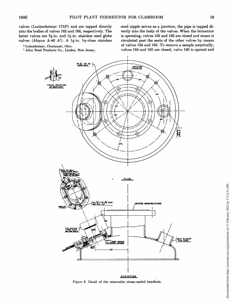
in the cover of the fermentor. A shallow groove is cutin the face of the flange, with an asbestos gasket form-ing the upper seal to the chamber. Steam is continuallypassed through the chamber when the handhole is inplace. A drawing of this arrangement is shown infigure 3.The temperature control system for the fermentor
a. 140
0c 17,4
R-2 l
F;A12 112167 DRv-2
68P0S-4 5 3
R-3
SOL-I
PR3-
%128
L R-1
ADDITIVERESERVOIRS
WATER
,SIGNALFROMREFRACTOME TER
PC-7DRV-I (0-60 PSIG)
AIR
IPOS-3 FI-3I
1/4"ACS
PC-I RV-1 RV-2(3OO0-30VAC) JOS
(0-4 V2 PSIG) PRESSURE,l)
C42 P21(Q) MA-I(41/t-30 PSIG) TK- I I jAINOCULUK.- 2 TK-1 ~~~~~~~~~~~~JACKET
122 ~~~FERMENTOR
AGITATOR
-A 6 ESUPPORT
S3 PRO BE~ ~t - 1 1 S1 123 RV;3 11 1/ W-SATMOS. R-1
147IT!OW COND C I 1SEWER
-l 1/4 SSP *154
*152 'EL-I
160To 171
-FRAG1METER
SAMPLE 156 162STEAMSEAL 163 161166
16
SAMPL
'33
TRC-2-V
135 134
IL0n0
102
I/4AdCS
1/4aSSP
AIR
PC-4(0-60PSIG)
132'__X
PA-3STEAM-AIRMIXER
TN
POS-2 AIR
1I4FI-2
I qrE PC-5A4V0-60
51PG)
LJL/COeOS
1I30 TRC-1
P1-6*104
1450PSG (O6PC 1G6, II
11 I
143
tEM BULB
1958] 17
r ssP
* 151l
TO*ANTIFOAMCIRCUIT
RETOI
PIPINGSYMBOL DESCRIPTIONP PROCESSW WATERS STEAMA AIRC CONDENSATE
SP STEEL PIPECK COPPER SERVICE, TYPE-KCS O.D.SOFT COPPER TUBINGSS STAINLESS STEEL O.D.TUBINGSI STAINLESS STEEL PIPE T.-316
li
.45
8
I
I
Dow
nloa
ded
from
http
s://j
ourn
als.
asm
.org
/jour
nal/a
m o
n 17
Feb
ruar
y 20
22 b
y 17
1.6.
31.1
80.
8G. J. FULD AND C. G. DUNN
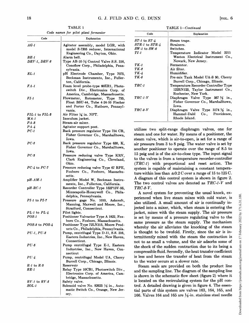
TABLE 1Code names for pilot plant fermentor
Code | Explanation
AG-I
BE-IDRV-I, DRV-2
EL-I
FA -I
FI-I
FIL-I to FIL-SMA-IPA -SPA-4PC-I
PC-2
PC-S
PC-4 to PC-7
pH-AM-I
pH-RC-I
PI-I to PI-7
PL-I to PL-4POS-I
POS-2 to POS-4
PU-I, PU-S
PU-S
PU-4
R-i to R-SRE-I
RV-1 to RV-5SOL-I
Agitator assembly, model LGR, withmodel S-7205 reducer, InternationalEngineering Co., Dayton, Ohio.
Alarm bell.Type AB-10-½ Control Valve S.S. 316,Conoflow Corp., Philadelphia, Penn-sylvania.
pH Electrode Chamber, Type 7075,Beckman Instruments, Inc., Fuller-ton, California.
Foam level probe-type 60ER1, Photo-switch Div., Electronics Corp. ofAmerica, Cambridge, Massachusetts.
Flowmeter, Rotometer, Type 735,Float BSU-44, Tube 4-24-10 Fischerand Porter Co., Hatboro, Pennsyl-vania.
Air Filter Y4 in. NPT.Inoculum jacket.Steam-air mixer.Agitator support post.Back pressure regulator Type 734 CR,
Fisher Governor Co., Marshalltown,Iowa.
Back pressure regulator Type 630, K,Fisher Governor Co., Marshalltown,Iowa.
Pressure reducing valve Type KRV,Clark Engineering Co., Cleveland,Ohio.
Pressure reducing valve Type 67 RPE,Foxboro Co., Foxboro, Massachu-setts.
Amplifier Model W, Beckman Instru-ments, Inc., Fullerton, California.
Recorder Controller Type 152P13V-95,Minneapolis-Honeywell Co., Phila-delphia, Pennsylvania.
Pressure gage No. 1010, Ashcroft,Manning, Maxwell and Moore, Inc.,Stratford, Connecticut.
Pilot lights.Positioner Valvactor Type A 1822, Fox-boro Co., Foxboro, Massachusetts.
Positioner Type 72LN315, Moore Prod-ucts Co., Philadelphia, Pennsylvania.
Pump, centrifugal Type D-11, S.S. 316,Eastern Industries, Inc., New Haven,Connecticut.
Pump centrifugal Type E-1, EasternIndustries, Inc., New Haven, Con-necticut
Pump, centrifugal Model UA, CherryBurrell Corp., Chicago, Illinois.
ReservoirRelay Type 10CB1, Photoswitch Div.,
Electronics Corp. of America, Cam-bridge, Massachusetts.
Safety valve.Solenoid valve No. 82625 ½ in., Auto-matic Switch Co., Orange, New Jer-sey.
TABLE 1-Continued
Code
ST-1 to ST-4STR-1 to STR-4SW-i to SW-6TI-i
TK-1TK-2TK-4TK-5
TRC-I
TRC-I-V
TRC-2-V
Explanation
Steam traps.Strainers.Switches.Temperature Indicator Model 2211Weston Electrical Instrument Co.,Newark, New Jersey.
Fermentor.Air filter.Humidifier.Pre-mix Tank Model UA-S 50, Cherry
Burrell Corp., Chicago, Illinois.Temperature Recorder Controller Type122RN125, Taylor Instrument Co.,Rochester, New York.
Diaphragm Valve Type 567 1 in.,Fisher Governor Co., Marshalltown,Iowa.
Diaphragm Valve Type 3174 X in.,Hammel-Dahl Co., Providence,Rhode Island.
utilizes two split-range diaphragm valves, one forsteam and one for water. By means of a positioner, thesteam valve, which is air-to-open, is set for a range ofair pressure from 3 to 8 psig. The water valve is set byanother positioner to operate over the range of 8.5 to15 psig and is of the air-to-close type. The input signalto the valves is from a temperature recorder-controller(TRC-1) with proportional and reset action. Thesystem is capable of maintaining a constant tempera-ture within less than 40.2 C over a range of 15 to 125 C.A diagram of this control system is shown in figure 2.The two control valves are denoted as TRC-1-V andTRC-2-V.A novel system for preventing the usual knock, ex-
perienced when live steam mixes with cold water, isalso utilized. A small amount of air is continually in-jected into a mixer, which, when steam is entering thejacket, mixes with the steam supply. The air pressureis set by means of a pressure regulating valve to thesame pressure as the steam supply. The mechanismwhereby the air alleviates the knocking of the steamis thought to be twofold. Firstly, since the air is in-termittently mixed with the steam the contraction isnot to as small a volume, and the air adsorbs some ofthe shock of the sudden contraction due to its being acompressible fluid. Secondly, the heat transfer coefficientis less and hence the transfer of heat from the steamto the water occurs at a slower rate.Steam seals are provided on both the product line
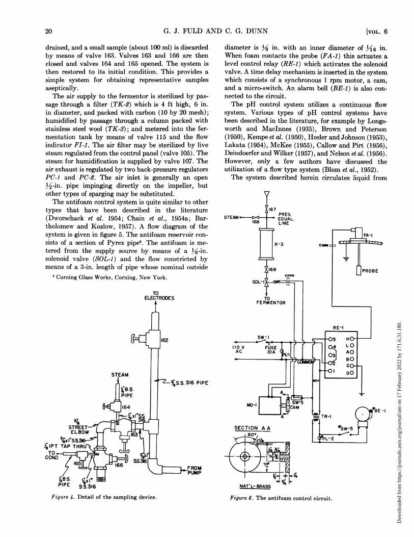
and the sampling line. The diagram of the sampling lineis shown in the schematic flow sheet (figure 2) where itis located on the recirculating system for the pH con-trol. A detailed drawing is given in figure 4. The essen-tial parts of this system are valves 163, 164, 165, and166. Valves 164 and 165 are }JA-in. stainless steel needle
18 [VOL. 6
Dow
nloa
ded
from
http
s://j
ourn
als.
asm
.org
/jour
nal/a
m o
n 17
Feb
ruar
y 20
22 b
y 17
1.6.
31.1
80.
PILOT PLANT FERMENTOR FOR CLASSROOM
valves (Lunkenheimer 17326) and are tapped directlyinto the bodies of valves 163 and 166, respectively. Thelatter valves are 38-in. and 12-in. stainless steel globevalves (Aloyco A-40 A7). A 34-in. by-close stainless
6 Lukenheimer, Cincinnati, Ohio.7Alloy Steel Products Co., Linden, New Jersey.
{6) 11- 150 mfCO L Si .J\
TYPICAL PROJECTIONOf COUPLINGS
steel nipple serves as a junction; the pipe is tapped di-rectly into the body of the valves. When the fermentoris operating, valves 163 and 166 are closed and steam iscirculated past the seats of the other valves by meansof valves 164 and 165. To remove a sample aseptically,valves 164 and 165 are closed, valve 166 is opened and
,, -PLAN
ELE VATION
Figure S. Detail of the removable steam-sealed handhole.
19581 19
Dow
nloa
ded
from
http
s://j
ourn
als.
asm
.org
/jour
nal/a
m o
n 17
Feb
ruar
y 20
22 b
y 17
1.6.
31.1
80.
G. J. FULD AND C. G. DUNN
drained, and a small sample (about 100 ml) is discardedby means of valve 163. Valves 163 and 166 are thenclosed and valves 164 and 165 opened. The system isthen restored to its initial condition. This provides asimple system for obtaining representative samplesaseptically.The air supply to the fermentor is sterilized by pas-
sage through a filter (TK-2) which is 4 ft high, 6 in.in diameter, and packed with carbon (10 by 20 mesh);humidified by passage through a column packed withstainless steel wool (TK-3); and metered into the fer-mentation tank by means of valve 115 and the flowindicator FI-1. The air filter may be sterilized by livesteam regulated from the control panel (valve 105). Thesteam for humidification is supplied by valve 107. Theair exhaust is regulated by two back-pressure regulatorsPC-1 and PC-2. The air inlet is generally an open½1-in. pipe impinging directly on the impeller, butother types of sparging may be substituted.The antifoam control system is quite similar to other
types that have been described in the literature(Dworschack et al. 1954; Chain et al., 1954a; Bar-tholomew and Kozlow, 1957). A flow diagram of thesystem is given in figure 5. The antifoam reservoir con-sists of a section of Pyrex pipe8. The antifoam is me-tered from the supply source by means of a h1-in.solenoid valve (SOL-i) and the flow constricted bymeans of a 3-in. length of pipe whose nominal outside
8 Corning Glass Works, Corning, New York.
TOELECTRODES
diameter is 18 in. with an inner diameter of 116 in.When foam contacts the probe (FA-i) this actuates alevel control relay (RE-i) which activates the solenoidvalve. A time delay mechanism is inserted in the systemwhich consists of a synchronous 1 rpm motor, a cam,and a micro-switch. An alarm bell (BE-i) is also con-nected to the circuit.The pH control system utilizes a continuous flow
system. Various types of pH control systems havebeen described in the literature, for example by Longs-worth and Maclnnes (1935), Brown and Peterson(1950), Kempe et al. (1950), Hosler and Johnson (1953),Lakata (1954), McKee (1955), Callow and Pirt (1956),Deindoerfer and Wilker (1957), and Nelson et al. (1956).However, only a few authors have discussed theutilization of a flow type system (Blom et al., 1952).The system described herein circulates liquid from
. 316 PIPE
SECTION A Ai600
MATL:MAT 'L- BRASS
Figure 4. Detail of the sampling device.
[VOL. 620
Figure 5. The antifoam control circuit.
Dow
nloa
ded
from
http
s://j
ourn
als.
asm
.org
/jour
nal/a
m o
n 17
Feb
ruar
y 20
22 b
y 17
1.6.
31.1
80.
PILOT PLANT FERMENTOR FOR CLASSROOM
the bottom of the fermentor, by means of a pump
(PU-I), past the pH electrode chamber (EL-I). Theelectrodes normally utilized have been the BeckmanType 8970-90 reference cell, Type 8990-90 glass elec-trode, and Type 7483 thermo compensator. The ampli-fier utilized is a Beckman Model W unit (pH-AM-i),whose output is recorded by the recorder-controller(pH-RC-i). The output from the recorder operates a
diaphragm control valve (DRV-1) which meters inbase as required from a reservoir (R-i). The reservoiris of 5-gallon capacity, and may be steam sterilizedfrom the central panel. A pressure balance line, con-
nected to the fermentor, permits the flow of alkali bygravity.
During sterilization, the electrodes may be removedfrom the chamber and the openings sealed with rubberstoppers. The chamber may then be sterilized withsteam. The electrodes may be sanitized chemically,and, after the fermentor is sterilized, replaced asep-
tically in the chamber. Since the only part of the elec-trodes which is in contact with the medium is glass, no
serious complications with contamination have beennoted. The sensitive wire connections need not besubjected to sterilization.
To allow maximum versatility in operation of the pHcontrol system, the valves DRV-i and DRV-2 are
equipped with positioners (POS-3, POS-4) and can beset with split ranges. Thus, both base and acid can beadded automatically if desired, in an analogous manner
to the steam and water valves on the temperature con-
trol system.An inoculum jacket is provided on the system, so
that inoculum can be added through this fitting. It can
be sterilized by steam from the control panel. How-ever, an external container must be attached to thejacket, and then inoculation made from this container.
DIscUSSION
The fermentation equipment described herein hasproved suitable for the operation of fermentations undercontrolled conditions. Aseptic conditions may be ob-tained readily throughout the system and be main-tained satisfactorily.The temperature control system operates satis-
factorily with varying loads with an accuracy of±0.2 C.The pH control system operates efficiently for the
automatic addition of alkali. Control to within ±t:0.1
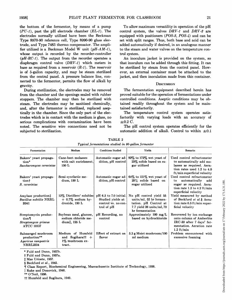
TABLE 2Typical fermentations studied in 50-gallon fermentor
Fermentation Medium Conditions Studied Yields Remarks
Bakers' yeast propaga- Cane-beet molasses Automatic sugar ad- 92% to 172% wet yeast of Used control refractometertion* with salt enirichment, dition, pH control 25% solids based on su- to automatically add mo-
Saccharomyces cerevisiae 150 L gar utilized lasses as required. Aera-tion rates used 1.2 to 4.0ft/min superficial velocity
Bakers' yeast propaga- Semi-synthetic me- Automatic sugar ad- 64% to 151% wet yeast of Used control refractometertiont dium, 150 L dition, pH control 25% solids based on to automatically add
S. cerevisiae sugar utilized sugar as required. Aera-tion rate 1.2 to 4.2 ft/minsuperficial velocity
Amylase productiont 12% Distillers' solubles pH 6.5 to 7.0 initial. No pH control yield 55 Yield measured by methodBacillus subtilis NRRL + 0.7% sodium hy- Studied yields at units/ml, 52 hr fermen- of Beckford et al.§ Aera-B941 droxide, 150 L control vs. no con- tation. pH Control at tion rate 0.5 ft/min super-
trol of pH 7.7 yield 28 units/ml, 70 ficial velocityhr fermentation
Streptomycin produc- Soybean meal, glucose, pH Recording, no Approximately 100 mg/L Recovered by ion exchangetion¶ sodium chloride me- control based on hydrochloride onto column of Amberlite
Streptomyces griseus diumll, 125 L IRC-50 after 7 days' fer-ATCC 10137 mentation. Aeration rate
1.2 ft/minSubmerged mushroom Medium of Humfeld Effect of extract on 5.3 g Moist mushroom/100 Problem encountered withproduction** and Sugiharatt + flavor ml medium excessive foaming
Agaricus campestris 1% mushroom ex-NRRL2334 tract.
* Fuld and Dunn, 1957b.t Fuld and Dunn, 1957a.t Mas Urioste, 1957.§ Beckford et al., 1945.¶ Class Report, Biochemical Engineering, Massachusetts Institute of Technology, 1956.Rake and Donovick, 1946.
** O'Neil, 1956.tt Humfeld and Sugihara, 1949.
19581 21
Dow
nloa
ded
from
http
s://j
ourn
als.
asm
.org
/jour
nal/a
m o
n 17
Feb
ruar
y 20
22 b
y 17
1.6.
31.1
80.
G. J. FULD AND C. G. DUNN
pH unit is possible. The system which utilizes bothautomatic base and acid addition has not been exten-sively investigated up to the present time. The majoradvantage of the present system is the ready accessi-bility of the electrodes.The automatic antifoam control system operates
satisfactorily, although a variable time-delay relaywould undoubtedly prove more convenient than thefixed delay system used at present.The fermentation equipment has been used success-
fully over a period of 3 years. Various kinds of aerobicpropagations and fermentations have been conductedwith the equipment. Among those investigated havebeen the propagation of bakers' yeast and mushroommycelium, the streptomycin fermentation, and theproduction of amylase (table 2).The fermentor has been employed for fermentations
in which refractive index was utilized to control sugarconcentration in a yeast propagation. Details of theseexperiments have been reported elsewhere (Fuld andDunn, 1957a, b).The equipment itself has been used for classroom
instruction in biochemical engineering for 3 years andstudents have been taught the basic principles of de-sign and operation of fermentation equipment withthis aid. They have been able to conduct successfulexperiments utilizing the equipment.
ACKNOWLEDGMENTSThe authors wish to acknowledge the contributions
of equipment and engineering design made by theArtisan Metal Products Co., Waltham, Massachusetts;Beckman Instruments, Fullerton, California; Minne-apolis-Honeywell Co., Philadelphia, Pennsylvania; andthe Vulcan Copper and Supply Co., Cincinnati, Ohio,which aided in the construction of the fermentor de-scribed herein.The assistance of Dr. Roger Stinchfield, Louis J.
Ronsivalli, and William G. Strovink in various phasesof the construction of the pilot plant is gratefullyacknowledged.
SUMMARYA 50-gallon pilot plant fermentor having provisions
for automatic temperature control, variable speed agi-tation, automatic antifoam control, automatic pH con-trol, and facilities for air sterilization is described indetail.The unit has been operated satisfactorily for a period
of several years and has proved a useful instructionand research tool.
REFERENCESBARTHOLOMEW, W. H., KAROW, E. O., AND SFAT, M. R. 1950
Design and operation of a laboratory fermentor. Ind.Eng. Chem., 42, 1827-1830.
BARTHOLOMEW, W. H. AND KOZLOW, D. 1957 Automaticantifoam control and nutrient feed for bench scale fer-
BECKFORD, L. D., KNEEN, E., AND LEWIS, K. H. 1945 Bac-terial amylases. Production on wheat bran. Ind. Eng.
Chem., 37, 692-696.
BLOM, R. H., PFEIFER, V. F., MOYER, A. J., TRAUFLER, D. H.,CONWAY, H. F., CROCKER, C. K., FARISON, R. E., AND
HANNIBAL, D. V. 1952 Sodium gluconate production-
fermentation with Aspergillus niger. Ind. Eng. Chem.,44, 435-440.
BROWN, W. E. AND PETERSON, W. H. 1950 Factors affecting
the production of penicillin in semi-pilot plant equip-
ment. Ind. Eng. Chem., 42, 1769-1774.
CALLOW, D. S. AND PIRT, S. J. 1956 Automatic control of
pH value in cultures of microorganisms. J. Gen. Micro-
biol., 14, 661-671.
CHAIN, E. B., PALADINO, S., UGOLINI, F., CALLOW, D. S., ANDVAN DER SLUIS, J. 1954a Laboratory fermentor for
vortex and sparger aeration. Rend. Ist. Super. SanitA,17, 61-86. (Eng. Ed.).
CHAIN, E. B., PALADINO, S., UGOLINI, F., AND CALLOW, D. S.1954b Pilot plant for fermentation in submerged culture.
Rend. Ist. Super. SanitA., 17, 132-144. (Eng. Ed.).
Class Report 1956 Biochemical Engineering, Massachusetts
Institute of Technology, Cambridge, Mass.
DEINDOERFER, F. H. AND WILKER, B. L. 1957 pH Control in
submerged pure culture fermentations. Ind. Eng. Chem.,
49, 1223-1226.
DWORSCHACK, R. G., LAGODA, A. A., JACKSON, R. W. 1954Fermentor for small-scale fermentations. Appl. Micro-
biol., 2, 190-197.FRIEDLAND, W. C., PETERSON, M. H., AND SYLVESTER, J. C.
1956 A fermentor design for small scale submergedfermentations. Ind. Eng. Chem., 48, 2180-2182.
FULD, G. J. AND DUNN, C. G. 1957a New process control
applications in fermentation. Ind. Eng. Chem., 49,
1215-1220.
FULD, G. J. AND DUNN, C. G. 1957b Automatic pilot plant
control in the development of microorganisms. Food
Technol., 11, 15-18.
GORDON, J. J., GRENFELL, E., KNOWLES, E., LEGGE, B. J.,MCALLISTER, R. G., AND WHITE, T. 1947 Methods ofpenicillin production in submerged culture on a pilotplant scale. J. Gen. Microbiol., 1, 187-202.
HOSLER, P. AND JOHNSON, M. J. 1953 Penicillin from chem-ically defined media. Ind. Eng. Chem., 45, 871-875.
HUMFELD, H. AND SUGIHARA, T. F. 1949 Mushroom myceliumproduction by submerged propagation. Food technol., 8,355-356.
KEMPE, L. L., HALVORSON, H. O., AND PIRET, E. L. 1950Effect of continuously controlled pH on lactic acid fer-mentations. Ind. Eng. Chem., 42, 1852-1857.
KROLL, C. L., FORMANET, S., COVERT, A. S., AND BROWN,W. E. 1956 Equipment for small-scale fermentations.Ind. Eng. Chem., 48, 2190-2193.
LAKATA, G. D. 1954 Apparatus for controlled fermentation.Appl. Microbiol., 2, 2-4.
LONGSWORTH, L. G. AND MACINNES, D. A. 1935 Bacterialgrowth with automatic pH control. (A) An apparatus (B)Some tests on the acid production of Lactobacillus aci-dophilus. J. Bacteriol., 29, 595-607.
MAS URIOSTE, J. 1957 Master's Thesis. Department of FoodTechnology, Massachusetts Institute of Technology,Cambridge, Mass.
McKEE, M. T. 1955 Bacterial culture with controlled pH.Appl. Microbiol., 3, 355-360.
NELSON, H. A., MAXON, W. D., AND ELFERDINK, T. H. 1956Small-scale equipment for detailed fermentation. Ind.
mentation. Ind. Eng. Chem., 49, 1221-1222.
22 [VOL. 6
Eng. Chem., 48, 2183-2189.
Dow
nloa
ded
from
http
s://j
ourn
als.
asm
.org
/jour
nal/a
m o
n 17
Feb
ruar
y 20
22 b
y 17
1.6.
31.1
80.
METHODS FOR DETECTION OF CHEMICAL MUTAGENS
O'NEIL, J. 1956 Master's Thesis, Department of FoodTechnology, Massachusetts Institute of Technology,Cambridge, Mass.
PALADINO, S., UGOLINI, F., AND CHAIN, E. B. 1954 Fer-mentors of 90 and 300 L capacity for vortex and spargeraeration. Rend. Ist. Super. Sanith. 17, 87-120. (Eng. Ed.).
PFEIFER, V. F., VOJNOVICH, C., AND HEGER, E. N. 1952Itaconic acid by fermentation with Aspergillus terreus.Ind. Eng. Chem., 44, 2975-2980.
RAKE, G. AND DONOVICK, R. 1946 Studies on nutritionalrequirements of Streptomyces griseus for formation ofstreptomycin. J. Bacteriol., 52, 223-226.
RIVETT, R. W., JOHNSON, M. J., AND PETERSON, W. H. 1950Laboratory fermentor for aerobic fermentations. Ind.Eng. Chem., 42, 188-190.
STEFANIAK, J. J., GAILEY, F. B., BROWN, C. S., AND JOHNSON,M. J. 1946 Pilot plant equipment for submerged pro-duction of penicillin. Ind. Eng. Chem., 38, 666-671.
Two Simple Methods for the Detection of Chemical Mutagens'V. N. IYER2 AND W. SZYBALSKI
Institute of Microbiology, Rutgers, The State University, New Brunswick, New Jersey
Received for publication Jupe 20, 1957
The demonstration by Muller (1927) and Stadler(1928) that mutations could be experimentally pro-duced by physical agents (X-rays) was one of the mostfundamental biological discoveries. Definite proof of themutagenic action evoked by chemical agents awaitedthe 1941 studies of Auerbach, published belatedly dueto circumstances associated with World War II (Auer-bach, 1951).Although Drosophila was the organism of choice in
the original investigations, microorganisms were soonrecognized as convenient tools for the study of chemicalmutagenicity (Horowitz et al., 1946; Tatum, 1946;Witkin, 1947; Bryson, 1948). Development of themutational system employing the streptomycin-depend-ence locus by Bertani (1951) gave further impetus tosystematic surveys of large numbers of chemicals formutagenic activity on bacteria (Demerec et al., 1951;Hemmerly and Demerec, 1955). The use of bacteria inmutational studies on carcinogens was reported inseveral papers (cf Scherr et al., 1954). These studiesdemonstrated a close correlation between the carcino-genic effect in mammals and the mutagenic effect onbacteria, stimulating a wide interest in this field. Otherfruits of this approach comprised the discovery ofsimple chemical substances capable of producing muta-tion within a wide range of concentrations in theabsence of significant lethal effects (Demerec andHanson, 1951), and the demonstration of a rathersignificant correlation between the antineoplastic ac-tivity observed in animal tumor experiments andmutational effects as assayed with the bacterial system(Gellhorn and Hirschberg, 1955). The subject is com-
1 Partially supported by a grant (#3240) from the UnitedStates Public Health Service.
2 Postdoctoral Fellow (United States Government, Ful-bright and Smith-Mundt Act). Present address: S. B. GardaCollege, Navsari, Surat Dt., Bombay, India.
prehensively reviewed by Boyland (1954) and Burdette(1955).The present paper describes further simplification of
the methods used for detection of mutagenic substancesamong pure chemicals and in complex natural sub-strates. The modifications introduced should pave theway for efficient large-scale surveys for these remark-able agents, which show pronounced direct or indirecteffects on the hereditary constitution of the cell nucleusat relatively nontoxic concentrations.
MATERIALS AND METHODS
Media. Difco nutrient broth (8 g per L) was em-ployed in most of these studies. Solid media contained2 per cent agar or 0.7 per cent agar (soft agar).Escherichia coli strain Sd4-73 was grown in nutrientbroth containing 20 ,ug per ml of streptomycin, whileits total count was scored on nutrient agar supple-mented with 100 ,ug per ml of streptomycin. The mini-mal medium (7 g K2HPO4; 2 g KH2PO4; 0.5 g Na3-citrate.5H20; 0.1 g MgSO4*7H20; 2.5 g glucose; 20 gagar; 1 L distilled water) for scoring of reversions in thecystine locus was supplemented with 100 ,ug per ml ofstreptomycin.
Strain. The streptomycin-dependent, cystine-re-quiring strain Sd4-73 of Escherichia coli was obtainedfrom Dr. M. Demerec of the Cold Spring HarborLaboratories. It was reisolated and a subculture selectedon the basis of a low background of spontaneous rever-sion in the streptomycin-dependence locus. This stepwas resorted to occasionally when the stock culturebegan to yield an increasing number of spontaneousrevertants.
Principle of the methods. The methods employ themutational system described by Bertani (1951) andsubsequently used by Demerec et al. (1951) for detection
19581 23
Dow
nloa
ded
from
http
s://j
ourn
als.
asm
.org
/jour
nal/a
m o
n 17
Feb
ruar
y 20
22 b
y 17
1.6.
31.1
80.