Embed Size (px)
Citation preview
A TECHNICAL STUDY
34 Redesign and renovation...................................27335 Study of Building Services and Installations....27836 Methodical design of load-bearing constructions
..............................................................................28837 Classification and combination..........................29438 Methodology and component development.....30639 Industrial design methods..................................31540 Future ICT developments..................................324
Construction technique serves spatial design. It is also a subject of education, study and development. Designing includes construction-technical design; linked with all other subjects of this book.
Re-design and renovationPresently the largest part of the built environment already exists; as soon as it is completed, a new building is added to the stock. An important dimension of the challenge of building for the future includes renovation, maintenance, re-adjustment and improvement of existing buildings (Verhoef, page 2).
Study of building services and installationsSchalkoort discusses the study of technical facilities in buildings most close to man: climate control, installations for transport, electricity, sanitary, communications, cleaning and risk prevention. The more space they require, the earlier its concern has to be involved in the process.
Methodical design of load-bearing constructions in buildingsKamerling discusses the study of technical facilities more remote from man, sometimes even invisible. This kind of study covers a limited range of scale levels and limited context variables. The resulting clear-cut considerations could serve as a prototype of more complex design study.
Classification and combinationIn this Chapter Cuperus argues that there are several ways to order building technique, each of them with a specific objective. Architectural transformations do not occur spontaneously. They result from human decisions, ultimately linked to the way components of the building are
connected. One approach may be to order building along the lines of the ‘building node’. The interface of the building node defines not only an ordering for the levels where decisions will be made, but also one with respect to sub-systems.
Methodology and component developmentComponents (‘constituent parts of a whole’) may be part of architectural (sub-)systems and separately developed. Eekhout argues how, in which case and context.
Industrial design methodsDesigning components resembles industrial design of loose products as done on the faculty of Industrial Design. De Jager refers to this branch of design methodology and discusses similarities and dissimilarities in context and methodology of product development, industrial design and architectural design.
Future ICT developmentsSariyildiz et al. indicate that both ‘hard’ and ‘soft’ computing techniques such as artificial neural networks, fuzzy logic and generic algorythms are helpful in complex design processes and architectural education. They discuss four application domains of ICT: creative-design, materialisation, realisation, and process and management.
ConclusionTechnical design is an interface between hard knowledge as discussed in the previous sections, and soft growing concepts. They are subject of the next sections.
1 RE-DESIGN AND RENOVATION
Leo Verhoef
34.1 Introduction.............................................27334.2 Dealing with the preliminary stage and the
stage of the project study......................27334.3 Example “Conceptual study of renewed
use of buildings”.....................................27434.4 Developing usage concepts for building ‘x’27534.5 Conclusion...............................................276
1.1 IntroductionBuildings ultimately reach the end of their life-span. Various notions may be implied by ‘life-span’, like:
Economic life-span; after which it is not attractive any more to maintain a material, building component or building.
Functional life-span; the degree in which the building is satisfactory for carrying out the function for which it was designed is an important part of the economic life-span.
Technical life-span literally means the end. The material from which the building is constructed is giving up, or materials seeing to the coherence of the building. For important parts of the building, like the skeleton, this may take a much longer time than the economic life-span.a
Reaching the end of one of these stages of life-span may cause terminating the life of the building, by demolishing it. In what is following here that option, and others, are discussed.When buildings have arrived at the end of their functional-economic life-span, the technical life-span has not been reached by far, generally speaking. At this point a number of decisions are possible:
Demolition and building anew. Increasingly, the environmental costs of processing the debris of the demolition can not be waved; to this the use of energy for manufacturing new products should be added, actually. On the social level there is increasing pressure against demolishing buildings with a sound potential for renovation. The quality of the overall structure is important;
Continuation of usage. Given the fact that the building has ceased to function properly, the user will only be prepared to lengthen his use at significantly lower costs. From an economic viewpoint the building is valued lower.
a Kristinsson, J. (2000) Lecture-text.
Re-design with renovation activities. Buildings are increasingly adapted to a (re)new(ed) use. The aim of this is to see to it that the building is functioning properly; in this, innovative energy concepts are taken explicitly into account: for instance active – and passive – solar energy, or the application of façade variants, like a second façade skin, or a climate façade.
1.2 Dealing with the preliminary stage and the stage of the project study
Dealing with re-design and renovation of buildings may distinguish a preliminary stage and the stage of the project study itself.The preliminary stage serves to reach a decision for recycling and renovation.b Topics like a market study are coming to the fore in order to tune locations, buildings and functions; global analysis of the building in which situation, possibilities of usage and general properties are addressed; and an investigation into special aspects with regard to the building and the location, like environmental and other requirements, rights and obligations associated with the building and possibilities for subsidy. Conclusions regarding possibilities for re-design and renovation as well as an estimate of costs, usually on the basis of characteristic numbers compared to building from scratch; or demolition and building from scratch finalise this stage and indicate the financial framework for the project study.
During the stage of the project study a number of steps may be discerned as well. It starts with the in-take, followed by a stage in which the location, the building and the function are analysed, after which the development of concepts for usage is conducted. This is leading to selection of one of the concepts (possibly with variants), followed by materialising the concept in its relationship to the budget.
The stage of the project study starts with an accurate survey of current conditions. These may be itemised according to
b Rongen, C.T.H. van (1988) Hergebruik van gebouwen, een verkennend onderzoek.
location, building and usage; with the purpose to find out what is valuable in the existing situation. It may be that the value of an ensemble, building or setting is already protected, for instance in the case of a monument, creating restrictions and other possibilities for re-design and renovation. Generally speaking, such a protection does not apply. Collecting or producing material that should be recorded by drawings, photographs and maps is an element of this stage. In order to clarify matters by way of an example, a study of Delft University is described globally, in which the task was undertaken to study how usage of a specific built ensemble could be improved upon. Since the preliminary stage or project stage did not apply, the conceptual project study could start immediately.
1.3 Example ‘Conceptual study of renewed use of buildings’ a
The approach of such a project study is illustrated by an example taken from practice. It concerned four buildings functioning as offices with its associated functions as well as laboratory functions. Management wanted to find out how many people could be housed in the built ensemble, if the laboratory part could be allocated to a building created separately. The underlying thought was strong reduction in use of space by the laboratory caused by IC technology.
Figure 1 ((…))
General points of departure for the study included:a Verhoef, L.G.W. and A.J. van Stigt (1994) Conceptueel
onderzoek naar het hergebruik van de gebouwen.
Interventions for adaptation of the existing buildings ‘w’, ‘x’, ‘y’ and ‘z’, for new functions are applying to office housing with associated functions, like conferencing rooms, meeting rooms, office restaurant.
Separation of functions; and, if possible, per part of the building. Mixing functions, like those of offices with laboratory ones, is no longer desirable. Laboratory functions should be housed in a separate building;
Concentrating the functions associated with housing offices as much as possible.
Solving the problems related to fire security and the view from the low building ‘x’;
Modernising the buildings in such a way that it gives a ‘corporate identity’ feeling.
In the general approach to this stage of the project study the following was mentioned already:
In-take; Stage of analysis of building and function; Development of concepts of usage.
After this, the selection is following one of the concepts with possible variants, then materialising the concept as related to the budget.
The building in-take regarded architecture, usage, technical possibilities of adapting on the basis of construction/ detailing and quality of maintenance, particularly of the façades.
During the analysis stage of the building and functions a number of conclusions was drawn based on the in-take that should lead to improvement. The most important ones:
In an architectural sense:
The buildings are not displaying a lower and upper side;
The columns, placed out of the façade by more than one metre, are not functioning as such, in order to interrupt the horizontal character of the 170 metres long buildings. The length is staying dominant and the building remains anonymous;
The buildings have a strongly defensive character, since the walls reach 1,1 m. above the floors;
The detailing of the stairs system in brick is not in harmony with the heavy columns in the façade;
The nine aerial bridges are too many for giving clarity to the structure of access.
Figure 2 ((…))
Figure 3 ((…))
From a viewpoint of usage:
The drawings show that many spaces are not used as an office. The buildings can be used more intensively than up to now;
Building ‘x’ with its dimensions of 80 by 120 m. is not obeying legal requirements with regard to lighting and view. Separate study concerning adaptability of building ‘x’ is called for;
The bottom glass line on 1,2 m. above floor level is clashing with the legal requirement of 0,9 m.;
Parts of building ‘x’ must be removed in order to comply with legal requirements for daylight and view;
Analysis shows that raising the floors housing the ducts for new usage is preferred to lowering the beams of the façade, and with it the glass line.
Figure 4 ((…))
In a technical sense:
The façade features a very special construction. The columns outside of the building have been linked to the monolith concrete façade beams by pre-fabricated concrete linkages. The link has been realised by hanging staves and short concrete elements. In this case the technical detailing is so important, that long-term and controlled protection is deemed necessary. The conclusion drawn from the analysis caused selection of skin sheltering from rain around the inner directed side of buildings ‘w’, ‘y’ and ‘z’ and to cover the streets between these buildings and ‘x’ with a hood from glass. This selection is also enabling the appropriate ‘corporate identity’ and the creation of an inner world;
The foundations and the construction are demonstrating after repeated calculation so much reserve, that an additional floor can be constructed on the building;
The beam on the ground floor breast-high has no significance for the construction. By removing it and adding a floor, the building is getting, by the changes proposed, in addition a lower and an upper side in an architectural sense.
Figure 5 ((…))
Figure 6 ((…))
1.4 Developing usage concepts for building ‘x’
Building ‘x’ has a U-shaped skin with a rather office-like look, with in-between a space with the structure resembling a hall. The point of departure of the study concerns maximising the number of office working places. Legal requirements concerning light and view are making the present form unacceptable and are necessitating partial demolition. On this basis 6 variants were developed: 3 on the basis of large atrium shapes and 3 on more linear ones.
A one single atrium building;B a double atrium building;C an E-structure;D a structure in lines ( | | | | );E a П П structure;F a mixed structure (U U).
Figure 7 ((…))
After an analysis of all concepts variant F, with a (U U) structure proves to be the most satisfactory one. It has a central area immediately behind the central entrance in building ‘z’. This leads to a continuous language of forms in the covered inner streets parallel to the buildings ‘w’, ‘z’ en ‘y’. By the intervention the areas at the roofed central hall and at the atria get a language of forms differing from the façades, but one that is consistent and continuous.In this concept all buildings must be accessed by a double ring structure including the aerial bridges. Since the inner areas have been covered, the glass enclosures of the existing aerial bridges have become redundant: free elements in space, demonstrating their primary function. Each area and building with covered streets protecting the existing façades gets a character of its own. The inner world created this way stands in open connection with the spacious central area with a roof 36 metres wide.

Figure 8 ((…))
When conceptual selections for usage and architecture have been made, materialising and detailing as related to the budget is called for. With regard to the objective of the present book, ‘Ways to Research and Study’, the process has been described in large strides in terms of what is needed when it comes to re-design and what the most important factors are.For smaller components within the whole – for instance in the case of the new outer façades – the same procedure is followed. Then also the ‘in-take’ is the basis; and then, specifically:
Data and dimensions of the existing façade; Stage of analysis of the façade and its
function. This causes the new outer façades, second ones, while the solar energy generated is used during winter and disposed of in summer;
Developing the usage concepts
Selection of one of the concepts with possibly variants for the outer façade and then materialising the concept as it is related to the budget for the façade.
1.5 ConclusionIn the case that there are weighty arguments for extending the life-span of a building, re-design and renovation are called for. In the above the various stages of study have been discussed on the basis of an example taken from practice. The constructive part of the building was emphasised, and checked on quantifiable life-spans, like economical, functional and technical ones.The type, size and state of the technical installations of a building are at least as important for judging the architectural state; since that is not only made on measurable properties, but predominantly on emotional results. A climate is up to a large degree a feeling and is therefor not to be measured objectively. One should use the work of behavioural sciences. The next Chapter will discuss this in more detail and provide examples.
2 STUDY OF BUILDING SERVICES AND INSTALLATIONS
Bob Schalkoort
35.1 Introduction.............................................27835.2 Climate control........................................28035.3 Transport installations............................28535.4 Electrical installations............................28535.5 Sanitary installations..............................28635.6 Communication installations..................28635.7 Façade maintenance equipment...........28635.8 Preventing risks of complaints..............28735.9 Difference between classroom and
practice....................................................287
2.1 Introduction2.1.1 Building services: objective and meansThe purpose of building services and installations is to support the building functions, so that buildings can fulfil their functional demands. They can also be a means to ensure that buildings answer economic or societal purposes. Finally, technical installations can be a formative factor in determining the shape of the building.In that case, contrasts between styling and functionality can come into being and should be balanced against each other: a subject of research.
2.1.2 Scope of the researchExamination of building services and installations entails a wide range of purposes, subjects, applications and methods, from technical studies focused on development of equipment and systems to investigations relying on specific methods to measure the effects of such installations on people. One aspect of the application study relates to the design of installations as part of the design process of buildings. ‘Technical’ studies with aspects of social sciences focus on problem solving in the case of complaints and on development of diagnostic methods. Study centring in methods from social sciences is the exploring and hypothesis formulating study needed in order to know installations as they relate to the building and building occupants as a risk factor. Ultimately this study also serves improvement of building
installations and their application and to improvement of the design process.
2.1.3 Problem-solving studiesSuch studies normally take place in response to specific complaints from building occupants. If it is suspected that the cause may lie in technical installations, it is customary for investigation to be carried out by maintenance technicians. Such first line surveys are often performed in response to an “explanatory complaint”, in which people do not say what is bothering them, but what they think is causing the problem.a First-line investigators normally do not know what to do with complaints about headaches, dry skin, contact lens problems and such. In order to change their situation, affected people tend to mention a cause, like “the air conditioning does not work properly”, because technicians will respond to that. If these complaints are taken literally, it is likely that the wrong track will be followed and the real cause will never be found, also because the appropriate experts may not be employed. Complaints on head-aches and such-like can have many causes; as do causes hailing from the building, type of work and the complainers themselves. When a situation has developed with a great many unexplained complaints the idiom ‘Sick Building Syndrome’ may well be used.In order to prevent originating that syndrome and to lower the number of unexplained complaints, diagnostic methods have been developed for first-line investigations.b This teaches researchers to take complaints seriously, but not literally.Questions are used in order to ascertain what is ailing complainers and what they experience. The conditions prevailing in the building pass muster systematically with the help of a checklist to make an inventory
a Schalkoort, T.A.J. (1987) Sick Building Syndrome, bewonersklachten, mogelijke oorzaken en oplossingen.
b Schalkoort, T.A.J. (1988) Wat wordt verstaan onder 'Sick Building Syndrome' en hoe moet met het daarbij behorende klachtenprobleem worden omgegaan?; Schalkoort, T.A.J. (1991) Ontwikkeling en behoud van gezonde kantoorgebouwen - Studie naar het 'Sick Building Syndrome' en de mogelijkheden van het terugdringen van bewonersklachten in kantoorgebouwen.
of possible causes of complaints. The investigator must try to find a likely solution by matching the list of complaints with possible causes.a
If the first-line investigation does not yield results, specially trained second-line investigators can be called in. They frequently work as described above, but are more knowledgeable and experienced, and can carry out measurements. In case this inspection also does not yield results, the survey can be extended and the building investigated in its entirety, taking into account risk factors in the surrounding area, the work place and the organisation. This type of investigation is similar to “Building in Use” evaluation and methodologically comparable to ‘Post Occupancy Evaluation’, see also page Error: Reference source not found.
2.1.4 Hypothesis-formingHypothesis-forming is carried out on the assumption that there is a relation between certain aspects of buildings and specific health complaints. This type of examination is often carried out as an epidemiological study. Many of these studies have been executed in order to gain insight in the causes of the “Sick Building Syndrome”.bThe most important conclusion was that the more influence the inhabitants of a building have on their situation, the less they complain.They should be in a position to operate the climate control and shading installations themselves, as well as to open windows.Characteristic for study in epidemics is the large scale with which data is being assembled. For study as considered here, usually dozens of buildings are investigated. Next to the properties and characteristics of the buildings themselves,
a Kurvers, S.R. (1994) Handleiding voor de aanpak van gebouw- en werkplekgerelateerde klachten.
b Finnegan, M.J. , A.C. Pickering et al. (1984) The Sick Building Syndrome: prevalence studies; Burge, P.S., A. Hedge et al. (1987) Sick Building Syndrome: a study of 4373 office workers; Kröling, P. (1988) Health and well-being disorders in air-conditioned buildings:comparative investigations of the building illness syndrome; Preller, L., T. Zweers et al. (1990) Gezondheidsklachten en klachten over het binnenklimaat in kantoorgebouwen.
data is collected on environment, installations, furnishing, type of work done in the building and the inhabitants. Key instruments of study are a questionnaire presented to the inhabitants, a building checklist and a measurement protocol. Development of these instruments has received a lot of attention internationally; with the objective to lessen the ambiguity of the results in order to make them better mutually comparable.A certain size of the population to be studied (buildings and people) is necessary for reaching reliable statements on possible relations. Statistical considerations determine the size through the number of relations that should be demonstrated and through the statistical distribution of properties and characteristics. These relations and distributions must be known for determining the population size, and consequently for performing the study. At the same time, the study is precisely undertaken to get to know them: a well-known methodological problem and subject of discussion; as in ‘objective orientated’ and ‘means orientated’ study.c For meaningful study – however vague it may be – there should be an idea about possible relations. Usually, ideas come into being during problem solving studies. Furthermore epidemiological study is not more than a hint that, possibly, causal relations exist. Causality and the question whether one factor influences the other, or vice versa, may be demonstrated by intervention study.
2.1.5 Intervention-studyIntervention study entails changing one factor under controlled conditions; that is to say that all others remain constant. The effect of that one change is then measured. This way a causal relation can be demonstrated. Intervention study can be conducted in normally functioning buildings as well as in laboratories. The most convincing kind is a ‘double-blind’ c Bergh, W.H.J. van den, A.C.J.M. Eekhout et al. (1999)
Methodologie is elkaars methoden begrijpen; Eekhout, A.C.J.M. (2000) Over de dialoog tussen doel- en middelengericht ontwerpen.
study. Then not only the persons studied, but also the people conducting the study are not aware of the fact of whether something has changed; and what has changed. The conditions prevailing when nothing has changed serve as ‘control’ population.The study of an effect of a factor on people, for instance a factor of the internal environment, may be needed to get insight into the ‘dose/effect relation’. Such a relation provides a basis for developing norms for an acceptable dose (and with that an acceptable effect). This study may be conducted in normally functioning buildings as well as in laboratories. In many cases the study is performed by universities or scientific institutions.
Intervention study may also relate to a factor in a process. The usefulness of the diagnostic method described in paragraph ((...)) for better dealing with complaints, for instance, can be studied. For performing the study a number of buildings should be considered, let us say twenty. The buildings should be largely comparable in terms of size, usage and inhabitants composition. Before the intervention the situation should be measured by presenting a questionnaire to the inhabitants. That may be a sample, for instance one of 10% of the inhabitants. It should also be ascertained how complaints are being taken care of in the buildings concerned. Management of, say ten, buildings may be provided with the diagnostic method employed, for instance in the form of an expert system. The management of ten other buildings (the control group) just get general information. After six months, and again after a year all buildings are measured and conclusions may be drawn from the differences.An intervention study of the effect of a particular design method may be imagined as well. A study like that could be performed in architectural education.
2.1.6 Development-orientated researchThe development of equipment and systems entails more technical research. In this
connection, one can think of investigations into cooling capacity of a chilled ceiling, the energy yield of an absorption-cooling process, the airflow pattern of an air supply grating, and similar issues. The purpose of this research is to attain (more) insight into how these systems work and / or how to improve their functioning. The analysis may also be related to energy use, life span and production methods. Manufacturers or large users of building installations (e.g. utilities companies) usually carry out this type of work.In a limited number of cases, study of this type is conducted at universities, like at the Faculty of Mechanical Engineering and Maritime Technology in Delft.
Developers seldom publish their study or study methods because they do not profit by that; for reasons of competition. Because of this, the study does not achieve scientific status. That does not imply that the study could not stand scrutiny of scientific criticism. Development study executed by universities is often published. In commissioned studies one is more secretive.
Research reports have to include the subject of investigation, description of the experiment set-up, methods and instruments; measurement results; analysis methodology and results (often graphs or mathematical models). Typical of this type of investigation is use of a model for the subject under investigation.For example: in the case of the cooling capacity of a chilled ceiling it is known approximately how things work. On the basis of data from the literature it is possible to describe a theoretical model; like the heat transfer between the cooling water and the indoor space that can be described with empirical relations and “non-dimensional” numbers like those of Nusselt, Prandl, Grashof and Reynolds.a A trial installation and measurements are needed in order to be able to determine the a Knoll, W.H. and E.J. Wagenaar (1994) Handboek
Installatietechniek.
co-efficients in those relations, since they depend on characteristics of the airflow along the ceiling. The behaviour of the air current varies between a laminar stream and turbulence and also has the characteristics of a mixture of both natural and forced convection. The description of the theoretical model is one initial step in the development study.
2.1.7 Application-related investigationApplication-related studies may concern the effects of heating, ventilation and airconditioning (HVAC) installations on indoor environmental conditions, or on people. These studies can be conducted in normally functioning buildings or a laboratory. Indoor climate conditions are charted using checklists, questionnaires and measurements. People’s reactions are measured by having them answer questions with a questionnaire. During study in a laboratory it is possible to objectify human responses by measuring physiological functions: heart beat, oxygen uptake, skin temperature.
The conclusions of the study are usually formulated quite carefully, since they are also based on statistical analyses of subjective data collected by means of questionnaires. With this type of analysis several techniques are used in order to be able to demonstrate relations.a Although execution of the study and the manner of reporting usually obey scientific standards, the results are seldom published in refereed scientific journals; rather during international congresses like ‘Healthy Buildings’, ‘Indoor Air’, ‘Clima 2000’, as well as congresses of the American ASHRAE and in the ‘ASHRAE Transactions’, published as a scientific journal next to the professional ‘ASHRAE Journal’, are highly esteemed.
2.1.8 Design-orientated studiesDesign study is a form of application study. Such investigations are used to work a Orlebeke, J.F. , P.J.D. Drenth et al. (1983) Compendium
van de psychologie. Dl. 8. Methoden van psychologisch onderzoek, het verzamelen en scoren van data, statistiek.
out which technical or architectural facilities are necessary for meeting the functional requirements of a building with given characteristics and intended use.In addition to selection of the system, design study is aiming for the dimensioning of facilities. The study of the functional requirements based on the function of the building, is an essential part of this study.Various installations are needed to make buildings fit for their function:
climate control (heating, cooling and ventilation)
transportation (elevators, escalators and similar)
sanitary facilities (hot and cold water supply, sewage)
electricity (lighting, power supply for machines and equipment)
communication (telephone, data, security and similar)
maintenance of building envelope.
In the paragraphs to follow , the design process of these functions and the type of research necessary will be worked out.
2.1.9 EvaluationDesign of building services and installations can be assessed beforehand (evaluation “ex ante”) and afterwards (evaluation “ex post”). “Ex-ante” evaluations are increasingly being carried out as part of the design process, because their use leads to better insight into the effects of the dynamic properties of the building than the usual static design methods. In such a case the aim of the evaluations is optimising the properties of the building; for instance to make mechanical cooling superfluous. The evaluation may also be needed to forecast the effect of specific installations under conditions not applied previously. See paragraph 2.2.4 on page 15 for a more detailed description of this study.‘Ex- post’ evaluation is needed to judge whether the functional goals of a design have been reached. This is the final stage of the design process that makes the design into a scientific feat, if the process is
regarded as an empirical cycle(see page Error: Reference source not found). A study like that is seldom conducted in practice if an architectonic design is concerned. This does not derive from the fact that there are methods known for conducting ex post evaluations. See paragraph 2.2.5 on page 15 for a description of the study concerning climate installations.
2.2 Climate control2.2.1 FunctionalityThe building functions determine the requirements in terms of comfort and usage that should be honoured by the indoor climate.The study of these requirements is the first part of the design study. Climate control may be realised by installations, constructional facilities or both.The shape and thermal properties of the building determine whether mechanical systems must be used or whether architectural provisions can be made. Comfort requirements and demands of use can be met by installations, provided they have sufficient capacity and are spatially positioned so that they do not cause annoyance. This demands something of the building: a sufficient amount of built-in space at an appropriate spot.
In order to be able to meet the requirements always, the installations must be accessible for maintenance and replacement. If the building should be flexible in terms of function or use, then the installations should also be flexible or at least adaptable. Insufficient built-in space leads to the use of installations that are too small; these do not have the required capacity, so it becomes too cold or too warm in the building, or stuffy. Or, these installations must do more than they are designed to do, without creating noise or draught problems. If terminal devices are wrongly located, it may cause draughts or unpleasant temperature gradients. These design mistakes can be prevented by ensuring that the architectural design and the design of
the load-bearing, partition, and finishing constructions are in tune with each other and are being carried out synchronously.
It seems logical that the functions of the building determine which demands the indoor climate must meet, and that is indeed true. It seems less logical, that it may not be clear during the architectural design process what the function is of a particular space, and thus, that it is also unclear which demands this spatial area must meet. Often it concerns spaces that originated as a consequence of the architectural design and not because of their being mentioned in the programme of requirements. Glass spaces and atria are well-known examples. It is also possible that spatial areas are created as required by the specifications, but for which it is predictable that they will not be able to meet the normal demands related to their function, regardless of the installations or architectural measures taken. It may be attractive, for other than functional reasons, to build such spatial areas as they were designed.In that case the function of the space or the permanent character of that function should be re-examined. Often, such re-examination is not - or not openly - carried out, which leads to a lack of clarity about the possible use of these spaces. This is not a design error, but a mistake in the design process.
This could be prevented by a project organisation in which all parties concerned, including client and future users, communicate openly about what is possible and what is impossible.
2.2.2 RequirementsUtility buildings usually owe their level of facilities to the requirements organisations put to them in their rôle of user. Inhabitants (people working in the building) have often different wishes. Not everything users or inhabitants expect of a building is made explicit as a requirement. For instance: a programme of requirements will never mention the quality of the water that should come out of the taps. Only if users or
inhabitants have experienced an aspect as a problem, it gets attention and will there be conscious requirements formulated. It is the task of architects and advisers to establish a balanced schedule and to communicate about it with those involved. Functional requirements to be reckoned with in an installation design have been formulated largely in laws, standards and other rules. They relate to the thermal climate (temperature, velocity and humidity of the air), airpurity (ventilation), lighting (luminosity, contrasts and colouring) and acoustics (amongst others sound levels and reverberation times). Collecting this data is the first step in the design study.
2.2.3 Design processBuilding and installation designThe indoor climate depends much of the time on the HVAC installations. This dependence is directly proportional to external loads (meteorological conditions, traffic and industry) and to internal loads (number of persons, artificial lighting, apparatus, production processes, building materials): the heavier the loads, the greater the dependence. The architect can influence this situation, primarily by reducing external and internal loads, and, secondarily, by reducing their effects.
A proper thermal insulation of the façade and use of sunblinds, keeping the solar heat out while allowing optimal daylighting, can reduce external heat load. An optimum is usually found by using adjustable (outside) sunshades. Tinted glazing and awnings also reduce at times when sun and daylight are needed. External load from emissions of annoying or harmful particles by traffic or industry can be reduced by not building in an area with traffic or industry. If this is not possible, the façade must be constructed in such a way that it can be properly closed off, and the building must be equipped with mechanical ventilation including a proper air-filtering system (see paragraph 2.8, page 19).
Internal heat load is strongly dependent on the use of a space. The power of artificial lighting can be reduced by using high / shallow spaces and by making the façade less transparent. To clarify: in order to attain comfortable relative brightness, artificial lighting is required in proportion to the transparency of the façade. The optimum lies at about 30% light openings in the façade (as seen from the inside). Extracting air through the lighting fixtures can halve the heatload from the artificial lighting. Advising the client to use energy-efficient equipment and computers can reduce heatload from appliances. In this context one can think of computer screens turning off automatically when not in use. Further, it is possible to directly extract heat and contaminants from apparatus, for instance, by using furniture with a built-in extraction system. Thus, 70% to 80% of the heat and contaminants of apparatus can be avoided.
The effect of heat load on the indoor climate can be reduced by a high capacity of heat accumulating mass. The mass absorbs heat during the day, emits it during the night. The mass of floors and partition walls is especially important. Preferably, the mass should not be shielded by false ceilings, panelling, raised floors, etc. Often, for reasons of flexibility, light movable partition walls are chosen. In practice, it turns out that many of these walls are never relocated. Here also are opportunities, if the designer can discuss this with the client. These opportunities are much reduced if the development is aimed at “the market’ and the location of partition walls is not fixed and changes per tenant.
Design process characteristicsDesigning building services and installations is an iterative process, working from generic to specific and from rough to fine. There are various descriptions of the processes. They have in common that the design process is divided into phases. A well-known example comes from the Dutch
‘Stichting Bouw Research’ (SBR) and ‘Instituut voor Studie en Stimulering van Onderzoek op het gebied van gebouwinstallaties’ (ISSO).a This description is summarised below and indicates for each phase of the design process which decisions must be taken with regard to technical and architectural aspects of building-design.
Phase Design decision onFEASIBILITY STUDY
objectives / functionsspatial needsfinancing
PROJECT DEFINITION
schedule of requirements thermal comfort lighting and air tightness and insulation
GENERAL LAYOUT(spatial design)
building structure outlinespatial layout & basic dimensionsbuilding shapezoning & compartmentationduct layout
PRELIMINARY DESIGN
building construction (=mass)façade constructionsunshade, glazing and U-valuesHVAC system selectionHVAC build-in space
FINAL DESIGN façade detailsglazing & sunshade systemsroof & floor detailsinterior & ceiling detailsHVAC system sizingcontrol systems
Table 1 Design process according to SBR/ISSOb
Characteristic of the design process is that decisions continually have to be made on the basis of data not yet available. For instance: in the General Layout (at the Faculty of Architecture in Delft usually referred to as Spatial Design), the overall layout and main dimensions of the air ducts have to be determined. To be able to do that, it must be known which HVAC system will be used. That, however, is not yet clear at the stage of the Spatial Design.
Moreover, at a later stage it may become clear that air ducts are not required at all, for instance, because natural ventilation will be all that is required. According to the
a Bergh, W.H.J. van den, A.C.J.M. Eekhout et al. (1999) Methodologie is elkaars methoden begrijpen.
b ISSO and SBR (1990) Ontwerpen van energie-efficiënte kantoorgebouwen.
scheme (Table 1), the choice of system must be made at the Preliminary Design stage. In practice, this is only possible when form and characteristics of the façade (glazing percentage, type of sunshading, etc.) and of partition-walls and finishings (heat accumulating mass, false ceiling, and such) are known. However, these aspects are only considered at the Final Design stage, not earlier.
The scheme shows that design decisions often have to be made on the basis of assumptions and that it has to be checked afterwards whether these assumptions were correct and whether earlier decisions perhaps have to be amended. In this lies the weakness of the design process, because the further the design has gone ahead, the more difficult it is to incorporate changes. On the one hand, this has to do with the fact that practical possibilities to incorporate changes reduce with the progress of the design, while, on the other hand, partners in the design process are increasingly less prepared to accept changes. Further, one wants to keep to the agreements so as not to endanger progress of the design process. The assumptions must, therefore, always be as realistic as possible and, during the whole course of the design process, the focus should be on reaching coherence between the various design aspects.
This may be achieved by selecting a design method guaranteeing this coherence – and thus optimal integration. The design of HVAC installations from the perspective of installation designers is described in “Concepten voor klimaatinstallaties”.c
Figure 9 schematically renders how a well-founded system selection can be realised. That does not mean to say that each and every installation designer does it that way.Installation designers do have their own methods; whilst rarely communicating about them among themselves. They often prefer certain systems while they have good experiences with them. An installation shows almost who designed it. The system
c ISSO (1998) Concepten voor klimaatinstallaties.
selection process described in “Concepten voor klimaatinstallaties” chooses the architectural sketch design for point of departure. Next to realising the programme of requirements an important objective is to conform to laws and rules, like those relating to energy conservation. Installation designers do feel themselves responsible for them and want to be held accountable.The result of the process described is a pre-selection of viable installation concepts and variants. The final selection has just been described globally in “Concepten voor klimaatinstallaties”. It is a study orientated on requirements of comfort and creation of sufficient built-in space, possibilities of maintenance and management, aiming at flexibility, cost control (investment, energy, maintenance, exploitation), restricting environmental effects and a sufficient performance in terms of energy. It has not been indicated how various aims and costs associated with attaining them are weighed against one another. It is most remarkable that the installation design is described as a free-standing process; not as a part of the architectonic/constructional design process.
Figure 9 Design process HVAC installations
Design methodDeparting from the given situation that with a design the road goes from generic to specific and from rough to fine, the installation design and the building design can be tuned increasingly better to one another during subsequent stages. The result of tuning always depends on the available data and on detailing those data. It concerns on one side constructional and physical data; on the other – as a consequence – data on the necessary installations and the built-in space needed.
The table “integration building and climate control systems” indicates which dataare required at each stage in order to achieve
optimal integration. The use of this method leads to an efficient design process, because the chance that in a following stage the building design may have to be changed substantially in order to accommodate the installations is reduced.
DESIGN STAGE
GENERAL LAYOUT
PRELIMINARY DESIGN
FINAL DESIGN
DIMENSIONING
“ROUGH” “GLOBAL” “FINE”
INTEGRATION STEP: based on: based on: based on:
DETERMINATIONREQUIREMENTS- indoor climate- indoor air quality- usage
schedule““
schedule““
schedule““
SYSTEM SELECTION
room typology
global calculation heat & cooling load
specific calculation heat & cooling load
HEAT STATION- location- dimensions
building volume
load estimation load calculation, apparatus choice and room layout
COOLING EQUIPMENT- location- dimensions * central station * cooling towers * decentral units
building volume“ “room volume
load estimation“ ““ “
load calculation
“ ““ “
AIR HANDLING- zoning <-room functions & building dimensions ->- central stations * locations * dimensions
zone volume estimation m3/h
apparatus choice calculation m3/h and room layout
DUCTS, PIPES ANDTERMINAL UNITS- locations- build-in space
system type estimation (load & m3/h)
calculation and apparatus choice
Table 2 Integration building and climate control
It is typical of this method is that the architect directs the installation design by designing the installations in their form and function.
Installation designers may provide support in the way described in the previous paragraph, but the architect remains responsible. The task and responsibilities of the installation designers are detailing and carrying out the calculations for what is chosen by the architect. The detailing concerns the choice of the installation components, dimensioning, cost control, energy consumption and other
environmental effects, preparing the specifications and contract documents, quality assurance during construction, etc.
2.2.4 Evaluation ex anteEvaluation ex ante of the design is possible by means of mock-up investigations or by using computer models. In the case of a mock-up study a space is built, life-size or on scale, with in it the HVAC and lighting installation designed; and in a stable situation measurements of temperature and air velocity are conducted on several point in that space. Summer and winter conditions are simulated by using warm and cold walls; the internal heat load from people and apparatus are reproduced by heating elements. This type of evaluation study is increasingly replaced by model testing using computer programs.For evaluation by computer, there are programs available that calculate changes in temperature with time, and programs that predict variations in temperature and airflow through a room.The first type of programs (TO), perform heat load calculations to predict variations in air and radiant temperature for a whole year, including the number of hours certain temperature limits are exceeded. See Figure9.
In order to include adaptive behaviour of people in the evaluation, there are programs simulating the influence of acclimatisation and clothing. These programs require input of room dimensions, composition and material properties of walls, windows, and sunshade systems, as well as the rate of use and the load from people, nd (lighting)apparatus apparatus. Cooling and heating capacity plus the control strategy for air supply and temperature also have to be entered. In these calculations, meteorological data from various weather stations and from different years can be used. The programs can calculate energy consumption for
heating, cooling and ventilation, and the energy performance of HVAC systems.Although such programs have been intended to evaluate installation designs, they are also used to test variants in order to optimise the installation design.
Figure 3
With current Computational Fluid Dynamics (CFD) programs, the temperature and air flows (direction and velocity) can be calculated for a space in a two- or three-dimensional grid. By these programs, one can determine the best location for end-apparatus, for instance, in order to prevent drafts occurring in the living area. In order to limit the input it is studied presently how TO and CFD programs may be linked to a graphic CAD system.a
Figure 4
Knowledge of the physics of the interior environment and of HVAC technology is needed for conducting this evaluation study aided by the computer programmes described here. In addition one should be able to use these programmes routinely. That is the reason that they are not in use – as yet – in regular architectural education. Presently it is being studied how to increase the practicability and accessibility of these programs to such a degree that they could be employed in design education and by architects as a design tool.b
2.2.5 Evaluation ex postTo finalise the design process, an investigation can be carried out to see whether the designed building meets the design requirements; on that basis the effectiveness of the design process can be judged.
a Hartog, J.P. den, A. Koutamanis et al. (2000) Possibilities and limitations of CFD simulations for indoor climate analysis.
b Hartog, J.P. den, P.G. Luscuere et al. (2002) A tool for thermal analysis of conceptual design.
In order to be able to determine whether the HVAC system has been designed effectively, it has to be determined whether the indoor climate requirements have been realised. These demands, however, are not sufficient to determine how occupants experience the indoor climate.a That is why occupant reactions also have to be analysed. For this investigation, “Post-occupancy” and “Post-project” evaluation methods have been developed.
A pre-cursor of the “post-occupancy” evaluation is the “Building in Use” evaluation, specifically intended to find explanations for complaints of building occupants.b
It is characteristic of these ex post evaluations that surveys have to be conducted and the occupants, or groups of them, have to be questioned with a questionnaire. The results are compared with the results of earlier building investigations. This procedure has provided extensive databases, from which increasingly reliable conclusions can be drawn.
Still larger collections come into being if the data of several researchers are linked. This has been done in the area of indoor climate study and resulted in increased insight in the human capability to adapt to the climate and in mechanisms influencing it.c This study shows that the preferred temperature in buildings with windows that may be opened is depending on the temperature outside more strongly than in buildings where that cannot be done. This means that buildings with openable windows need less cooling then the other type. This study confirms the idea existing for a longer time that buildings of the first
a Kurvers, S.R. and J.L. Leijten (2000) A comparison of a pre construction judgement of the design and a post occupancy evaluation in a large Dutch office building.
b Vischer, J.C. (1989) Environmental quality in offices.c Dear, N. and G. Schiller-Brager (1998) Developing an
adaptive model of thermal comfort and preference.
type need less rigorous temperature requirements.dInternational congresses have given a lot of attention ‘Building in Use’ study, particularly to the development of questionnaires with minimal length. It has been shown that the original lists of 100 to 200 questions could be reduced to some 15 to 20 questions. It is imaginable that 'post-occupancy’ and ‘post-project’ evaluations, meant for ascertaining whether realised buildings reach their functional objectives reasonably, may be shortened similarly in length compared to current practice.e
2.3 Transport installationsThe study of internal transport of people by means of installations (elevators, escalators e.t.q.) relates to an analysis of the demand for movement and to the performance requirements put to the transport system. This performance is determined by the impression users are getting of the ease with which the demand for movement is handled. For an objective assessment the interval time, as well as handling capacity, amongst others, are used as indicator. The interval time is the time passing between the departure of two cabins following one another from the reception lobby. For the handling capacity the percentage of the occupancy is taken that may be transported in five minutes. By ‘occupancy’ is meant the number of persons maximally present on the floors served by the elevator in questionThe demand for movement depends on usage and partitioning of the building and the location of the building with regard to public transport. Buildings close to a train or metro station have to cope with higher peaks in the demand for movement than buildings relying on private transportation. Horizontal distribution of the traffic flow from the entrance to the building may serve in first instance the lowering of the peaks at the elevators. Escalators are also used for this d Schalkoort, T.A.J. (1994) Normen voor een acceptabel
binnenklimaat.e Leaman, A. (1989) Building use studies, Post-occupancy
and post-project evaluation.
purpose. In the case of buildings for one organisation peaks are higher than in buildings housing several organisations with varying or ‘gliding’ shifts. In department stores, hospitals and opening times, visiting hours etc. are responsible for peaks. With varying shifts and the spreading of opening hours, peaks will be lowered and the performance of the transport systems improved.
In the case of a spatial design a global analysis of the traffic flow in the building usually suffices; location and number of elevators (and possibly escalators) is determined on the basis of tables and rules of thumb. For the preliminary design number, sizes, type of motor, steerage and elevator speed are often determined with the aid of simple calculation rules and statistics-based computer programs supplied by elevator manufacturers.a In the case of very high buildings – where vertical transport may be of great influence on the shape of the building – this study should be conducted during the spatial design stage. For the final design simulation programmes are available enabling study of the traffic; also between floors. For the study aided by simulation programs specific knowledge of transport systems is needed as well as routine in working with them. Elevator manufacturers and a limited number of consulting companies possess this knowledge and routine. In architectural education until now only use is made of simple calculation rules and of programmes based on statistical data.
2.4 Electrical installations2.4.1 LightingThe demand for artificial light within buildings depends on the presence of daylight. By tuning daylight and artificial light, a considerable amount of energy saving may be realised, particularly in utility buildings. As mentioned earlier, a lot of daylight does not mean that less artificial light is needed. Often it is just the a Schalkoort, T.A.J. (2000) Handleiding liftenprogramma.
other way round. More important than the amount of light (measured in the illuminance) is evenness of lighting. That is certainly applicable for spaces where work is done relying strongly on the visual function, when precise perception of small details is important, of slight differences in colour, or tiny contrasts. In the case of tuning the lighting on this limiting too large contrasts between work-surface (the task put to the eye) and surroundings is crucial, next to limiting reflections and blinding. However, it may happen that reflections and direct light are needed; for instance in order to perceive small faults in shapes or in properties of a surface. Optimal tuning is possible with regulating the amount of daylight as well as of artificial light. During the past two decades scientific study has been conducted of this combined control (also at the Technical University of Eindhoven).
Because of the development of artificial lighting, particularly fluorescent lamps (‘TL’), the interest in daylight as a light source was waning for a while. Windows got much more attention in their function of visual connection between inside and outside and as architectonic elements in order to create contrasts in the appearance. Precisely these contrasts may work out unpleasantly in rooms where specific visual tasks should be executed; or may be even too stark. This may then be corrected by artificial light, shading against the sun, curtains and their ilk; at the cost of the architectonic contrast intended, of course. This implies that there exists tension between functional requirements and architectonic design. Consequently, the two should be balanced.
For the stage of the spatial design a study of the type of lighting, placing the lights and spacing cables usually suffices. During the stage of the preliminary design the placing of the light-spots and detailing of the space are tuned to one another (compartmentalisation, lowered ceilings
etc.). At the final design it is studied which specific lighting fixtures are precisely needed in order to realise the requirements put to lighting in the project definition. The lighting requirements relate to strength, evenness, contrasts, colour rendering and colour temperature. Computer programs are available for studying type and positioning of the lighting fixtures that may be used; the size of the rooms and the reflection co-efficients of ceiling, walls and floors are input to these programs. They contain lighting technical data of a range of products. That is also the reason that these programs are usually made available by manufacturers or providers of the equipment needed.
2.4.2 Power supplyFor the design of the remaining electrical installations, like electrical power supply to equipment and machines, study is only conducted for the total needed and for the positioning and the space needed for transforming and housing electrical power and such like. For this, use is made of safety requirements – often formulated in national standards (e. g. NEN 1010) – of rules of thumb, and experiential data.a The physical hierarchy of electrical groups and switches is determined on the basis of constructional drawings. Knowledge and experience based on the lore of the craft is used. As far as known, scientific study is exclusively conducted in the areas of producing, transporting and distributing electrical energy.
2.5 Sanitary installationsSanitary installations comprise sanitary apparatus, facilities for producing and distributing hot and cold water. Facilities for sewage pipes for rainwater often is included. For the design of these installations as a whole, knowledge and experience based on the lore of the craft is used. The probability that this knowledge and experience is not used is large, since the importance of this ‘plumber’s work’ is a An. (1998) Elektrische installaties, ontwerp en
dimensionering: hoofdlijnen.
often recognised insufficiently. This importance concerns particularly the part of the sanitary installations that is taken into consideration in the architectural construction. If an insufficient amount of attention is given to this, cumbersome side-effects may emerge:water hammer, noise of flowing water, stench, sewage to the outside. When the building is ready, the possibility of correcting for them is usually slight. Trouble can be prevented by dimensioning pipes for hot and cold water, sewage and rainwater generously (but not too generously) with minimal curvature and – of course – by allowing for this timely in the architectural design, so that a sufficient amount of built-in space has been reserved. For sewage the horizontal pipes should have a slope not too slight; long horizontal pipes – certainly if they are realised within concrete floors – should be avoided as much as possible.
During the spatial design a study of the number, the most logical placing of sanitary equipment and of the horizontal and vertical built-in spaces is usually considered to suffice. The pipes are dimensioned during the preliminary design.b At the final design stage, the selection of the material and the connecting technique is determined.Increasingly, attention is being paid in the case of sanitary installations to environmental effects. In particular it is attempted to restrict the use of energy in the production of hot tap water, for instance by solar energy. Unfortunately water heated this way may provide ‘ideal’ circumstances for storage and growth of pathogenic micro-organisms like legionella pneumophila. Contamination can be prevented by heating water from solar energy always to 60 degrees Celsius minimally (electrically or with a heating furnace). See also paragraph 2.8, page 19.
2.6 Communication installationsIn order to be able to keep pace with the stormy developments in data b Schalkoort, T.A.J. and P.G. Luscuere (1996)
Binnenriolering en hemelwaterafvoer, ontwerp en dimensionering.
communication, utility buildings should have access to a flexible and adaptable infrastructure and built-in space to install such a structure and to expand it, if need be. Consider cabling, network servers, patch-panels and their like. The development is so highly paced that vested insight in this field may change within a very short time; sometimes months. The time needed to realise buildings runs a lot slower. This means that (optimising) study for data communication installations as they relate to design of the building is relatively senseless. A vision of the future provides a better basis for selecting and choosing. Up to now, raised floors, above a space that may be simply accessed (so-called ‘computer floors’) have proven to be the most flexible option. That does not prevent buildings with such floors from demonstrating similar Gordian knots of cabling as the buildings where ducts for cables (on walls or in floors) have been applied. Obviously one does not take the time to move furniture to provide access to the space under the floor. In both cases (computer-floors or ducts) ducts integrated in the furniture could provide a solution to reduce the mass of cables on the floor. Independent of this, data communication equipment and cables require less and less space; and instead of cables increasingly use is being made of infra-red transmission for communication between the pieces of equipment and between equipment and networks.
2.7 Façade maintenance equipmentArchitects should indicate how maintenance of the skin of the building can be done safely. It should be accessible safely in its entirety for cleaning windows, paint-work, inspection, replacement etc. Ladders are allowed up to a height of 10 metres for washing windows. Higher than that, a ‘cherry picker’ may be used up to a maximum of 25 metres, if it is placed sufficiently close to the wall and safely secured on the ground. At greater heights – and in the case of walls
bordering on ponds and inner gardens – they cannot be used and special facilities have to be implemented. During the spatial design the possibility of this type of maintenance should be studied, since it might cause adaptation of the shape of the building, certainly if slanting or protruding walls are considered. Large surfaces of panes under an angle, like those of conservatories and atria, should be studied for accessibility; in these cases also on the inside. At the preliminary design stage it should be checked how special facilities, like suspended access-equipment, can be implemented and what that entails for the detailing the wall and the construction of the building. During this design stage it should be studied, amongst others, how the suspended platform or chair can glide along the surface of the wall. During the final design stage the construction of the façade cleaning installation is dimensioned.
2.8 Preventing risks of complaintsPresently more than half of the occupants of office buildings is dis-satisfied with the internal climate. In other utility buildings as well (schools, hospitals and their likes) considerable dis-satisfaction is rampant. National and international studies show that a large part of this is caused by other aspects of the building than the HVAC installations.a Dis-satisfaction and complaints may be pre-empted by applying in each design stage a strategy that restricts or reduces risks of complaining. This strategy, often alluded to as ‘Healthy Building’b is best used by the designers of the building themselves. When other parties are being made responsible for reducing the risks of its study, the risk as described in paragraph 2.9.3 comes into being.
a Schalkoort, T.A.J. (1991) Ontwikkeling en behoud van gezonde kantoorgebouwen - Studie naar het 'Sick Building Syndrome' en de mogelijkheden van het terugdringen van bewonersklachten in kantoorgebouwen.
b SZW (1992) Gezonde kantoorgebouwen, aandachtspunten bij ontwikkeling en beheer; Schalkoort, T.A.J. and P. Luscuere (1997) Gezonde gebouwen.
2.9 Difference between classroom and practice
2.9.1 Research in learning situationThere is a difference between the study as conducted in the learning situation at the Faculty of Architecture and the study in practice. In architectural education fewer design stages are being gone through. Teaching restricts itself usually to the Project Definition (PD), Spatial Design (SD) and Preliminary Design. In a small number of exercises a Final Design (FD) is made.The learning situation at the Faculty is aiming at the emergence of an attitude where the constructional engineer in the making feels him/herself responsible for the installations of the building and for the functional goals that should be realised. In order to reach this aim in the learning context, study is also conducted that does not belong typically to the task of, for instance, architects, but to the one of installation designers and advisers. These exercises should give the experience what consequences certain constructional and architectonic design decisions entail for the type of installations and for the built-in space needed to house them.
2.9.2 Research in practicePractice comprises more stages of the design process than have been trained in the learning situation. In addition, some tasks trained for are executed in practice by advisers or installation providers. The study focusing on design and integration of the whole comprises in practice the stages of the programme, design, development, realisation and maintenance stages. As far as advisers and providers play a rôle there, the process for HVAC installations has been described in Publication 43 of ISSO.a It describes an ideal; practice is often different. ISSO casts the installation designer for a rôle within which the architectonic design is being followed. The architect has the initiative; regularly reporting and linking back is the name of the game. This pre-supposes that in each
a ISSO (1998) Concepten voor klimaatinstallaties.
stage of the design information is exchanged consistently. In practice this works often quite differently, since advisers or providers are getting more responsibilities and have to develop by themselves solutions for problems; even if these solutions can be found in the architectonic design.
2.9.3 Installation designersInstallation designers are aware of the fact that in the case of complaints on the indoor climate the accusing finger is readily pointed at the HVAC installations. They deem this to be understandable. Nevertheless, quite often the cause of these complaints must be allocated somewhere else. The phenomenon has been studied extensively; many congresses have been devoted to it. The solution is clear: installation designers should prevent during the design process the risks of complaints by warning commissioners and architects if they are forced to take risky design decisions. In reality most installation designers do like not to bother their clients and architects with this kind of problems. They are of the opinion – just like architects, by the way – that they have not been hired to warn for problems, but to solve them. In “Concepten voor klimaatinstallaties” this also shows.b By the same token installation advisers are sensing a dilemma. They must earn an income, but also the confidence sitting on their shoulders. Usually they opt for short-term success and decide to make the best of it and hope – often against knowing better – that the final result will just work out. Client and architect can prevent this type of behaviour – risky to them – by means of a project organisation in which open communication is encouraged and realisation of a perfect result is seen as a common responsibility.
b ISSO (1998) Concepten voor klimaatinstallaties.
3 METHODICAL DESIGN OF LOAD-BEARING CONSTRUCTIONS
Wim Kamerling
36.1 Problem Definition..................................28836.2 Methodical design...................................28836.3 Construction design of a building..........28936.4 Description of the method......................29036.5 Finalisation of the method.....................291
3.1 Problem DefinitionThroughout the last decades the building industry has changed considerably with regard to, for example, the use of construction equipment, logistics, products and management. These changes also affect the design process and the design methods for the design of buildings and for the design of parts of buildings like the load-bearing construction. Thus, because of increased complexity, buildings are more often designed by multi-disciplinary teams. Multi-disciplinary design is far from simple: part-products not independent of each other are designed separately and at a later stage part-designs often have to be tuned to each other (see page 28).
In order to ensure that the multi-disciplinary design process proceeds smoothly, design methods are required that permit concurrent and integral design of the whole building and the various parts. In order to attain optimal inter-action between the disciplines, methods which permit the design of the whole as well as part-products are preferred. The development of a method for the design of the support construction is based on a top-down approach. First, a general method for multi-disciplinary design is described and, next, this method is worked out for the design of support structures.
Authorities
Client Cost consultantConstruction consultant
Architect Installations consultant
Figure 10 The influence of the participants
Figure 10 shows the influence of the participants of the design team, the authorities, and the client on a design. The number of designers and the influence of the designers on the whole varies per project. An inter-disciplinary design only comes about when the designers go beyond the boundaries of respective disciplines and design the whole together.
3.2 Methodical designWhat is designing? Foqué presents the proposition: “Designing is a concept with a very polyvalent content”.a Eekhout, in the lecture notes for Design Methodology, gives an overview of the definitions used by lecturers at the different faculties of the Delft University of Technology, the Netherlands.b They show that the following facets are essential in designing: fulfilment of wishes and needs, taking decisions, shaping a product and originality. Based on these facets we can define the designing of the structure of a building as: to devise a system of building elements that can transfer the loads on a building to the foundations, while taking into account the limiting conditions dictated by the concept of the building.
Figure 11 Views of the future
Figure 11 shows the view of the future in politics, science and technology.c Like the politician, the designer tries to make the improbable possible. De Jong writes: “The designer has the task of exploring improbable possibilities, especially when the most probable development is not the one preferred. Because of their improbability, these possibilities are not predictable, one has to design them”.d
There are different schools of thought on design methods and designing. Often, a distinction is made between the intuitive and the explicit method. In essence, these two categories overlap. An explicit method always has moments in the process when a Foqué, R. (1975) Ontwerpsystemen, een inleiding tot de
ontwerptheorie. p. 13.b Ridder, H. de and A.C.J.M. Eekhout (1996) Lecture
notes design methodology.c Jong, T.M. de (1995) Systematische transformaties in
het getekende ontwerp en hun effect. p.14, fig. 9.d Jong, T.M. de (1995) Systematische transformaties in
het getekende ontwerp en hun effect. p.15.
intuition governs, and an intuitive method also has phases in which analyses and selections take place.
Figure 12 Schematic representation of the design process
In the divergence phase there is a marked increase in the number of possible variations and data. In the transformation phase concepts and solutions for part-designs are conceived. In the convergence phase the part-solutions are combined in alternatives and the preferred solution is chosen.e
A design method for multi-disciplinary design must be able to be applied independently of disciplines and must foster inter-action between disciplines; further, the method should not interfere with creativity. What needs to be determined is whether the analysis phase - creative phase – and execution phase modelf would be suitable, perhaps after some adaptation, for multi-disciplinary and interdisciplinary design.
The analysis phase - creative phase – execution phase model is as follows:
The analysis phase: the problem is identified; The creative phase, with three sub-phases:
analysis phase, synthesis phase and evaluation phase:
analysis phase: information collection, definition of the design criteria, classification of the design criteria;synthesis phase: devising part-solutions, combining part-solutions in alternatives;
e Foqué, R. (1975) Ontwerpsystemen, een inleiding tot de ontwerptheorie. p. 59
f Foqué, R. (1975) Ontwerpsystemen, een inleiding tot de ontwerptheorie. p.58.
evaluation phase: testing the alternatives, selecting the preferred solution;
The execution phase:the solution is presented in one form or another.
In the model, the creative part of the design process takes place mainly in the synthesis phase, when the solutions for the part-problems have been thought through and sub-solutions are combined in alternatives. Several methods have been invented to facilitate creative solutions, like:
associative methods; for instance brainstorming;
creative confrontational methods, using analogies;
analytic systematic methods, like the morphological method, in which the problem is split into part-problems and solutions for part-problems are combined to yield alternatives.a
The first two methods are used, by preference, to come to a new concept of solving the problem. The morphological method fits in well with the model described, because, also in this model, the design problem is split up into part-problems, the solutions of which are then combined in alternatives. The presentation of part-solutions and alternatives during the course of the design process is essential for multi-disciplinary designing. In the original model the presentation takes place mainly in the last phase. Because the members of the design team must tune their part-designs to the overall design, a continuous visualisation of part-solutions is essential for multi-disciplinary designing. For the sake of communication, the model must be extended in each phase with a visualisation of solutions and designs. During the last phase the chosen solution is further refined.
3.3 Construction design of a buildingThe design of the support structure is based on the architect’s spatial outline plan. In this plan, the volumes and sizes of the areas are indicated globally. This spatial plan, together with the programme of requirements, defines the part-assignment a Tiemessen, N.T.M., Methodic design, sylabus Post
HBO, Betonver., p.15. ((…))
for the design of the load-bearing structure. The design of a part-product is based on the detailed requirements which follow from the overall requirements. As the problem definition for the design of the part-product has already been defined in the analytical phase, a separate phase for the problem definition of the part-product is not necessary.The design of the support structure is worked out simultaneously with the other part-designs. Thus, the implementation phase of the part-design can co-incide with the implementation phase of the overall design, so that no separate implementation phase need be included in the part-design process.
In view of the above, one may postulate that for the design of a part-product like the construction of a building, the method can be condensed to the three sub-phases of the creative phase, i.e., analysis phase - synthesis phase - evaluation phase.
Figure 13 The Condensed model
This schedule shows the condensed model for the design of a part-product like the construction of a building.
3.4 Description of the methodPart-assignment The architect’s outline design is the basis for the design of the support structure. In this plan, a part-assignment, the volumes and the sizes of the various spaces are globally indicated.
AnalysisThe problem definition and the data are analysed, differentiating between the problems and the data related to the location and those related to the function of the building.
Analysis of the location:Investigation of the location and building site, adjoining buildings, cables and ducts, accessibility, site contours and elevation, soil profile, bearing capacity of the subsoil, drainage characteristics, climate and availability of personnel, materials and equipment. Determination of the variable loads on roofs and façades for the given site with regard to wind, snow, rain, earthquakes and similar.
Analysis of the object:The making of an inventory of the requirements with regard to safety, for instance, in case of a calamity like fire, and preferences with regard to construction time, costs, deflections, position of the support points and of the stability provisions. Determining the variable loads resulting from the actual use, like floor loads. SynthesisIn this phase, solutions for part-problems are devised and sub-solutions combined in alternatives.
Creation of sub-solutionsGenerating part-solutions for the construction of foundation, roofs and floors, which are essentially different with regard to shape and construction material. Investigate which stability provisions are feasible. For easy communication with other members of the design team, visualise the part-solutions with the aid of sketches which clearly show position and shape of the construction aspects.
Combining the sub-solutions Next, using a relationship matrix, the investigation focuses on which part-
solutions for roofs, floors, and foundation can be combined in construction designs. Eliminating non-feasible alternatives at an early stage saves much time in combining the sub-solution.
Making a display of the alternatives using sketches clearly showing form, position and dimensions. At this stage, the dimensions are determined globally only; for instance by rule of thumb and simple calculations.
Function subsolution
D1
D2
D3
V1
V2
F1
F 2
Roof D1 1 1 1 1D2 1 0 1 1D3 1 0 1 1
Floors V1 1 0V2 0 1
Foundation F1F2
Table 3 Relationship matrix
At the intersection points of the horizontal and vertical axis, 1 indicates that the sub-solutions can be combined, 0 that they cannot.a There are in principle 3*2*2=12 combinations possible for the sub-solutions. After evaluation just four combinations remain: D1V1F1, D1V2F2, D2V1F1 and D3V1F1.
EvaluationFor evaluation of the alternatives, the criteria and their weightings are determined. Selection criteria may be, for instance, costs, aesthetics, feasibility, usefulness and load on the environment. Next, alternatives are compared with each other using the evaluation matrix.
a Idem, p.18. ((…))
Selection matrix
Weight A1 A2 A3 A4 A5 A6Criterion 1Criterion 2Criterion 3Criterion 4Total
Table 4 Selection matrix
The selection matrix with the alternatives in the rows and the selection criteria in the columns.
FinalisationIn the finalisation phase, the dimensions of the building elements are checked, cost estimates made, and design and construction drawings prepared for the selected alternative design.
3.5 Finalisation of the methodThe method described can be applied to any type of building regardless of its intended use. Because many buildings are very similar from the point of view of their construction, buildings can be classified, and for each class a design method can be specified. In line with established practice, we distinguish, as an initial division, between building dwellings and industrial plants. In building houses we distinguish between one-family housing and apartment buildings. In industrial buildings we differentiate between one-storey, multi-storey and high-rise. These different categories differ both in the loads they are exposed to and in the design solutions.a For instance, the roof construction and the ground floor construction are essential for the design of a one-storey building, while for a multi-storey building the floor construction at the different levels is important and for a high-rise building not only the floors at the different elevations, but also the bracing structures are of great importance.
a Kamerling, J.W., M. Bonebakker et al. (1997) Hogere bouwkunde Jellema. Dl. 9. Utiliteitsbouw; bouwmethoden. p.7.
Figure 14 The classification of buildings
For further clarification, the method is worked out for the design of a unit of the classification, i.e., the design of the construction for one-storey buildings.
Figure 15 Low-rise building
Figure 15. A one-storey building is a building with one main building layer, with possibly locally a mezzanine or landing.b The height of the building is not essential to the classification. The shipbuilding yard for Van der Giesen – de Noord, for instance, is 52 m high, 97 m wide and 264 m long.The design of the support construction of a one-storey building is based on the outline design of the building with the volumes and sizes of the spaces indicated. We discern the following steps:
AnalysisThe problem definition and the data are analysed. Apart from the aspects mentioned in the general description, we specify the following aspects for one-storey buildings: Analysis of the location Investigating whether the one-storey building can be placed on footings, if b Kamerling, J.W., M. Bonebakker et al. (1997) Hogere
bouwkunde Jellema. Dl. 9. Utiliteitsbouw; bouwmethoden. p.144
necessary after soil improvement, or whether a pile foundation is necessary. Determining the variable loads on roofs and façades at the given location with respect to wind, snow, rain, earthquakes etc.
Analysis of the object Making an inventory of the preferences with regard to construction time, costs, deflections, position of support points, shape of the roof and position of the provisions for stability. Determining the variable loads on the ground floor and the horizontal loads from building cranes. Listing the preferences with regard to settlements. Investigate the possibilities with regard to locations for support points and provisions for stability, and the possibilities with regard to the shape of the roof: flat, sloping, curved or double curved.
Figure 16 Ruimteplan
Figure 16 is an outline design of a swimming pool. This layout makes the position and size of the building elements visible, and the spaces located within.a
SynthesisThe generation of sub-solutions and the analysis of the sub-solutions Analysing which construction solutions are feasible for the roof construction, starting with the position of the support points, possible roof shapes and the position of the possibly necessary stability provisions.a Tol, A. van and R. Jellema (1983 ) Bouwkunde
voor het hoger technisch onderwijs. Dl. 11. p.1
Devising types of construction that fit the roof shapes, which differ from each other in shape and construction material, and draw the roof plans.
Figure 17 Possible roof shapes
Possible roofshapes: Flat roofs with a linear support structure like
beams, trusses, pre-stressed beams, cable-stayed beams and portals;
Flat roofs with a neutral structure like space frames and beam rasters
Sloping roofs: three-hinged frames and folded roofs
Curved roofs: arches and barrel vaults Double curved roofs: domes, conoide shells
and hyppar shells.
Analysing the possible types of floor construction; investigate for instance whether a reinforced concrete floor, a steel-fibre concrete floor or a prefab floor on a raster of beams is feasible. Analysing the possibilities with regard to the foundation, investigate whether a foundation on footings is possible, (if necessary after soil improvement) or whether the building will have to be supported on piles; and investigating whether the top layers of the soil are strong enough to carry the loads during construction from, for instance, building cranes, storage of construction materials and the pouring of concrete.
Devising part-solutions for the floor construction and the foundation, and visualising them.
Combining the sub-solutionsNext, the relation matrix is used to investigate which part-solutions for the
roof, the ground floor and the foundation can be combined in construction designs. The different part-solutions for the construction of roof, floor and foundation are placed in the relationship matrix. Then, the investigation focuses on which part-solutions for the roof construction, the floor construction and the foundation fit together with regard to load transfer, and can be combined in designs for the whole building. Making the alternatives visual in sketches of the plan layout and cross-sections in which shape, position and dimensions of the various construction elements are brought out. At this stage, the dimensions can be generally determined by rule of thumb and simple calculations.
EvaluationFor evaluation of the alternatives, the criteria and their weights are determined and ordered. Next, alternatives are compared to each other using the evaluation matrix. The alternative that meets the requirements best is selected and further worked out.
The design method for the construction of a one-storey building can be developed for other types of buildings.
The preceding displayed a scheme with combinatorial possibilities between variants of foundations, floors and roofs ((…)). The variants of the foundation may be combined with some floor-systems, not with others. The combinatorial possibilities with foundation variants x1…xm and floor-systems y1…yn may be rendered by a m x n matrix
y1 … yn
x1
…
xm
Table 5 ((…))
The readings are limited to 1 and 0, possible and impossible. However, the elements in the matrix may also indicate the
price at which a contractor is prepared to connect the foundation to the floor-system. An extremely high price is economically equivalent to ‘impossible’, but we should keep the possibility in mind, for everything here is possible technically speaking.A matrix like this can now also be made for the combination of m floor-systems Y and o roof-systems Z and for the combination of n foundation-systems X and o roof-systems Z. The total number of technical possibilities is then n times m times o. The connection between foundation, floors and roof is formed in this case by a system of columns and/ or walls between them and the design of that system is depending on the combination selected from the possibilities mentioned.
This example should make clear that three aspects are of importance on this level: the components (here: foundation, floors and roof), the connections between these components and their size-co-ordination. The last one is, for instance, of great importance for the economical feasibility of a foundation-system with a floor-system. When the size-system of the foundation is differing from the one of the pre-supposed points of support of the floors, the connection may become expensive and perhaps even ‘impossible’ economically.
Obviously, the number of combinatorial possibilities is determined in the first place by what is considered a ‘component’ (classification). In order to be able to combine these components, several connections are required: between foundation and ground floor, between columns and floors, and between columns and roofs.
Therefore, a study of designing methodically carrying constructions leads by the same token from combination via classification to the ‘building node’.
4 CLASSIFICATION AND COMBINATION
Ype Cuperus
37.1 Ackermann’s classification....................29437.2 Educational classifications.....................29537.3 Building-trade classifications.................29637.4 Classification for decision-making........29637.5 Systems of Counting and Modular
Systems...................................................29737.6 Modular Co-ordination as an International
Norm........................................................29737.7 The Importance of Co-ordination of
Positioning...............................................29837.8 Synthesis of Positioning and Measuring
Co-ordination...........................................29837.9 From de-linking to interface...................29937.10 Building Node as an Interface...............30037.11 Classification according to Positioning.30037.12 Classification according to adaptability 30137.13 Position and adaptability combined......30237.14 Dependency diagrams............................30237.15 Classification as to production..............303
Different ways exist for classifying components. Each classification serves its own purpose. This Chapter discusses several classifications. In a design for a building, components are combined into an ordered whole. The ordering of the positioning and size of the components constitutes the essence of the design, execution and usage of buildings. In order to be able to classify, the components should first be brought under the same nomer. Classification is the condition for combination.
Every classification of components generates problems of definition: should a floor be regarded as a load carrying component? For a floor is featuring a separating function as well. And should the walls always be regarded as separating components? Some walls are displaying a carrying function after all. By the same token, a global distinction between carrying and separating does not suffice: the classification should be worked out further; and this leads readily to complicated classifications of components and their definitions. In addition, the number of kinds of connections between all these components is growing. Perhaps these should be distinguished further in connections with the forms of points, lines,
planes or three-dimensional structures; each of them with carrying and/ or separating functions; or both. But is it not better in that case to regard the connections as starting point, while defining the components between them? The focus shifts then to the ‘building node’.
First, different classifications are described as seen from the practice of education, building and research. Next, an ordering of the combinations of components is explained as related to the history of the origination of modular co-ordination for building in The Netherlands. The shift from building to fabrication and assembly caused an inquiry into another, new classification of the components. The state-of-the-art of the most recent building node study is described. This is the foundation for consumer-orientated, industrial, flexible, decomposable and thereby sustainable building.
All the classifications demonstrate a range of scale overlapping with the semi-logarithmic range of nominal radii and their nomenclature earlier mentioned in the present book:
Nominal radius Name
30m Building complex10m Building3m Building segment1m Building part300mm Building component100mm Superelement30mm Element10mm Subelement3mm Trade material1mm Composition material<1mm Material
Both within the Faculty of Architecture of Delft University and outside it, different classifications of components have been used in education over the years. Building practice employs its own. These classifications will be described here;
starting with those of a book dearly beloved at the Faculty of Architecture.
4.1 Ackermann’s classificationThe book ‘Grundlagen für das Entwerfen und Konstruieren’ (Basic Principles of Design and Construction) by Kurt Ackermann deserves sincere appreciation because it defines, in 150 pages, very many aspects of the technical design of buildings. The author discriminates between spatial structuring (planning, design, dimension control systems), function (placing the different functions in relation to each other, and their connection to corridors, stairs and elevators), load-bearing constructions, divided according to their composition principle (column versus load-bearing wall), type of building (high-rise, single storey), but also main building elements (foundation, roof, façade, etc.) and material (timber, steel, concrete, etc.). Further, he treats physics as applicable to buildings, construction connections and technical installations. He concludes with the subject ‘form’. The book, the product of one person only, takes a didactic approach to architecture and construction, starting out with technical issues which lead finally to the definition of form.a
a Ackermann, K. (1983) Grundlagen fur das Entwerfen und Konstruieren.
Figure 18 Structure according to Ackermann
At Delft University, every subject in the structuring by Ackermann has its own specialists who, as a team, teach and carry out research on technical aspects of design and building. Until 1975, the Faculty of Architecture comprised five sections dealing with building-technical matters: three for ‘Building Constructions’ which followed the yearly curriculum (first and second year; third year; forth and fifth year), the Section Industrial Building, sub-divided according to construction material (concrete, steel, timber), and the Section Applied Mechanics. These last two sections were more orientated towards design and were part of the annual curriculum.
4.2 Educational classificationsTo bring some order into the growing volume of building-trade data, In the seventies, Gout, a Professor of building technique, used a system that differentiated between ‘partitioning’, load-bearing’, and ‘facilities’, crossed with a division according to ‘function’, ‘materials’ and
‘construction’.a After 1979, this system was no longer used and lecture notes again became more traditional, addressing principles and particular solutions in architecture and building design.
Figure 19 Subject coding according to Gout
In 1977, Dijkstra defined ‘integration levels’: the first integration level is that of basic knowledge (like applied mechanics, physics as related to buildings), the second integration level deals with the knowledge and practice to integrate various building-construction disciplines on the level of an actual building design. Dijkstra taught the second level of integration in his legendary project lectures, in which, for eight consecutive weeks, the project design and the implementation were explained by people with hands-on experience.b
During the eighties, a simpler structure for the department was put into place, related to graduating specialities, in which technical installations and physics as applied to buildings (and, temporarily, building economics) formed the sub-department group Architecture and Urban Technology (AST). This structuring, based on the way teaching was organised, was provided by successive professors and staff members who often had earned their spurs in practice, not in research or teaching.
In the course of time Chairs were modified, like the change of the Chair ‘Materials and Creative Design’c to ‘Product Development’ (Eekhout). Teaching a Gout, M. (1973) Bouwmethodiek I. 2e bundel.b Dijkstra, T. (1970) Gebouw Afdeling Bouwkunde TH,
Berlageweg, Delft, bouwkundig ontwerp.c Zwarts, M.E. (1983) Bouwmethodiek 1.
activities always followed the structuring according to integration levels, whilst changing the definition of tasks and fields of activity of the chairs made it possible to stay in touch with real-life.d
Brouwer, Professor in Building Technology from 1991 to 2000, pleads for integration. Then it will be possible, by clever design, to combine functions, for instance in a façade panel. By providing the parapet of a façade with a combined heating / cooling / sun-shade system, which works independently from the rest of the building, it is possible to save money on large installations and related space requirements of air ducts, where additional expenditure follows from thinking in separate systems.e
In design, an almost endless series of decisions is required before the built environment actually comes into being. Trotz, Professor of building technique from 1994 till 1999, ordered these decisions by category and translated them into a checklist, which the various parties, under the direction of the architect, can go through. Because the check list, in first instance, is written on the process and not on the end product, the list is long, regardless of the size of the result.f
The architectural field can be structured in many more ways, for instance according to type of production (once-only or industrial), discipline (foundation, façade, roof, etc.), scale, sequence, economics, culture, time, environment. All systems of structuring serve their own purpose and, because the building industry serves many purposes, no particular system of structuring is optimal.
4.3 Building-trade classificationsThe Netherlands Building-trade Documentation (NBD) is a loose-leaf d Woord, J. van der (1994) Een kleine historie van het vak
op de faculteit.e Haartsen, J., J Brouwer et al. (1999) De intelligente
gevel.f Trotz, A.J. (1999) Lamme hand achter blinde vlek?
system of product information. It uses the SfB classification system. The NDB describes it as follows: “It is a classification system for all information relevant to the building industry. This system was developed in Sweden in 1950 and has been accepted internationally”. The system divides the building process into: substructure, superstructure, completion, finishing, provisions for installations, standard layouts, variable fittings and building site. All data ‘relevant to the building process’ is placed in one of these groups. The system uses an extensive letter / numbering code.a
The Standard Specification for Housing and Industrial Buildings (STABU) uses its own system for the classification of products. This system is geared towards writing specifications. Typical for the classification of products is that, by rigidly staying with the system, the ‘General’ section keeps on growing, because very many items either do not fit one particular section or belong in more than one section. For instance: should data on sun-shades be placed in the category ‘sun-shades’, because they are sun-shades, or in the category ‘façade systems’, because sun-shades are procured and installed by the supplier of the façade, or under ‘aluminium’, because the sun-shade contains aluminium parts for which the specifications contain general conditions?b
4.4 Classification for decision-makingInstead of dividing the building trade according to ‘things’, there is much to be said for making a division based on the parties that decide over these ‘things’. This idea was worked out for the first time in the beginning of the sixties by Habraken and the Foundation for Architectural Research, Eindhoven, at which time ‘support' and ‘infill’ were defined. The support is that part of the building about which the inhabitant has no say and the a NCA Vakdocumentatie (1999) Nederlandse
bouwdocumentatie.b STABU, Stichting (1999) Standaardbestek Burger en
Utiliteitsbouw.
infill is the part about which the inhabitant has full say.c Later, other decision making levels were identified, like ‘tissue’, refering to town planning.
Figure 20 Levels of decision making
Van Randen, Professor for building technique from 1973 till 1991, further detailed the sub-division of the decision-making process. He described the building process as the ‘spaghetti-effect’: pull one strand and everything starts to move in an arbitrary way.
Figure 21 Van Randen characterised the power game in the building process as 'the spaghetti– effect'
Because decisions by the parties involved result, in the end, in decisions about materials, it was proposed to ‘un-couple’ building elements by proposing rules for location and size of the building elements.d
c Habraken, N.J. (1961) De dragers en de mensen, het einde van de massawoningbouw.
d Randen, A. van and L. Hulsbos (1976) De bouw in de knoop.
This led to extensive research into modular co-ordination in house building, resulting in yet another classification of components. The basis was division of a building into ‘building parts’. The groups of building parts defined were: load-bearing walls, floors, roofs, façades, inner-partitioning and wall lining, equipment, ducts and services and spatial areas. By agreeing, for each building part group, on certain rules about dimensions (multiples and parts of 30 cm) and locations (on an imaginary grid), the freedom of choice for the various parties involved would be exactly known, and this would make the building industry more efficient.a
The division into building part groups, intended for structuring the building process, was also used in teaching. The building technique was explained using ‘double pages’ with, on the left page, the general considerations and, on the right-hand page, the specific solutions.b
When the components to be used are known, they must be combined within a plan for the building. This could be achieved by using mathematical models. In architecture this usually happens by a design process. During building the components are connected to one another. Connecting, joining, linking, coupling, fitting or interface determine whether a combination works. Sizing and positioning of the components establish the complement of the connection. Since the beginning of the sixties elaborate study into this has been undertaken; under the umbrella ‘modular co-ordination’.
4.5 Systems of Counting and Modular Systems
Systems of scale and measure are significant for building in two ways. In the first place, they are a system for counting. All sizes may be expressed in the system of units chosen. But, even since early days a a NNI, Nederlands Normalisatie Instituut (1981) NEN2883,
Regels voor gecontracteerde experimenten met modulaire coördinatie voor de woningbouw.
b Randen, A van (1979) Dakdiktaat.
second application demonstrated itself: a modular system. Then, the rôle of the measuring system does not stay limited to counting. It has consequences for the positioning and sizes of the building element itself. The brick with its derived measures for length, width and height provides a classical example. Modular systems entail great advantages for communication, since they allow standardisation. Not only the brick itself, but different building elements could be expressed in an earlier stage in these measures.
Figure 22 Koppenmaat
This standardisation enabled pre-fabrication. A carpenter could make sliding windows with a reasonable certainty that they could be applied in projects. A commission for a window-frame could be formulated simply in a number of heads and layers. This enhanced communication enormously. In the early days the measure of heads and layers were just regionally significant, since the shape of the brick varied per region. Then, following the Building Law of 1901 that caused the emergence of a national building market, the ‘Waal’ format proved to be triumphant with a
layer thickness of 6,25 cm. Sixteen layers make one metre: the modular system (brick module) and the counting system (the metre) were coupled.a
4.6 Modular Co-ordination as an International Norm
After the Second World War modular co-ordination was getting new impetus, also a new basis. During the industrial effort connected with the war a vast body of experience with mass-production came into being. The merits of standardisation were discovered. These achievements should also be employed in building: not only for rapid re-construction, but also to build a counter-weight in Western Europe against threats from behind the Iron Curtain.The ISO, the International Organisation for Standardisation, was called into being with for its aim world-encompassing uniformity of normalisation. The NNI, the Netherlands Normalisation Institute, is member of ISO.
The new basis for modular co-ordination in building was fixed by ISO on a basis module M of 100 mm and a preferential module of 3M, 300 mm. In this way a synthesis of the metric system and the anthropomorphic system of inch, foot and yard came into being. This way, 100 mm is roughly 4 inches and the preferential module of 300 mm is rounded off to 1 foot. That industry influenced modular developments greatly can be explained from the history of the rise of ISO. The options were determined by producing, rather than by those prevailing while building. Industrial considerations, like assortment restriction were rampant. Architectural conditions, like simple joining and inter-weaving – and the forming of spaces as well – was subservient to it.
Almost all industrialised countries prescribed a norm for modular co-a Carp, J.C. (1983) Modulaire coördinatie, een hele
geschiedenis.
ordination in building on the basis of the ISO guide-lines. The version of the Netherlands was published in 1964. It is a two-page document, NEN 5700, wherein just the basic module M of 10 cm is fixed and a system of reference, ‘a three-dimensional grid of planes perpendicular to one another on a mutual distance equal to the basic module M. This system serves as a point of departure for the positioning of all building elements’. One year later, a norm was published, entitled ‘Modular Co-ordination for Building. Tolerance System’. In it, the concepts related to tolerances were defined, like placing a modular building element in the grid, tolerance of manufacture, positioning tolerance, maximal and minimal impact of joining.b
4.7 The Importance of Co-ordination of Positioning
Modular co-ordination in building in the Netherlands took a turn differing from those in other countries. Architects were feeling ill-at-ease with norm NEN 5700, given its undefined determination of position.The architect is not developing products, but designing buildings. By the same token he is not dealing with parts, but the whole. Joining, inter-weaving and forming of spaces are essential problems to him. All solutions should be studied for three-dimensional consequences; also on positions very distant in the building. Therefore, it is important that the elements do have a fixed position. Differences in size should not lead immediately to adjustments, having an inclination to reproduce themselves well into the remotest fringes of the building. In addition, a second characteristic of the work of the architect is important. Each and every design is always developing in steps. The interest of the architect is entailing that each subsequent step does not undo the previous one. This adds to the importance that the elements are staying in place. Further detailing to be b Carp, J.C. (1983) Modulaire coördinatie, een hele
geschiedenis.
considered may not trespass on positioning of building elements.
Then, a variant on the ISO proposals was generated among architects in which positioning was called for. It departed from an alternative modular grid with a one-to-one relationship between modules M and 3M: the M was positioned at the heart of the 3M grid-lines. These were the proposals of SAR, Stichting Architecten Research, a group of architects interested in furthering industrial ways of production in residential building; amongst other aims. The modular proposals had to enable separation between ‘carrier’ and ‘appurtenance’. The emancipation of the appurtenance and equipment was seen as a way to create a space where the resident may decide for himself.
The SAR proposals were well received domestically; and outside the country. They also caused dis-enchantment. The positioning leap of 3M was experienced by architects as huge, particularly in residential building. Producers were of the opinion, that the SAR proposals were veering too much into the direction of positional fixing. The fixing of measuring was deemed to be left in jeopardy.a
4.8 Synthesis of Positioning and Measuring Co-ordination
The new interest as well as criticism caused the NNI to re-install the Norm Committee. Norm NEN 2880, ‘Modular Co-ordination in Building’ was published in 1977. The positioning systemising of the SAR was endorsed and a lot of attention spent on the determination of measurement. A ‘modus operandi’ was proposed, how sizes could be deduced. As far as the determination of sizing is concerned, NEN 2880, however, was rather a methodology than a norm.By the massive production in residential building in series, the need emerged for a norm regulating the determination of proportioning in residential building more a Carp, J.C. (1983) Modulaire coördinatie, een hele
geschiedenis.
precisely; this became NEN 2883, ‘Modular Co-ordination for Residential Building’. It may be regarded as a synthesis of the developments described above. The norm regulated positioning as well as sizing prescriptions and was furthering as such the interests of builders as well as producers. It did enable the architect to work from what is global to what is detail, and to change building material in a later stage, since the co-ordination of positioning prevented that changes in size were transferred, ‘radiated’ to elements elsewhere in the building.b
Figure 23 Plattegrond ruimteplan volgens NEN2883
Figure 24 Plattegrond materiaalplan volgens NEN2883
The norm disconnected carrier and equipment; so that separate parties could decide independently within their own range of influence. The tuning of sizing and positioning also allowed that different disciplines could work next to one another during construction.
The consequences for products and ways of producing have been studied carefully in extensive consultation with industry. The norm distinguished between different ‘partial building groups’, like carrying construction, roof, façade inner walls, etc., all suggested by different disciplines with
b Carp, J.C. (1983) Modulaire coördinatie, een hele geschiedenis.
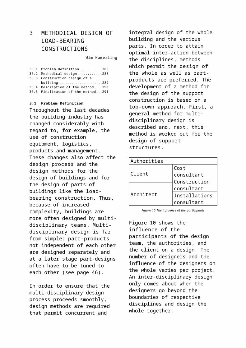
their own conditions and requirements. The spatial norms to be attained in residential building were included in the considerations as well, since minimal sizes of spaces are often dominant over the sizes of materials. ‘Space’ was one of the partial building groups.
In spite of all these advantages, NEN 2883 had to face resistance in building practice. The rulings determining measure and position were rather abstract and kept themselves aloof from the practice of drawing boards and building site. At the time the norm should start to apply, the building industry was faced by serious recession, so that it could impossibly invest sufficiently in the apparatus of production. By increasing automation in production due to CAD / CAM and the logistics of Just-in-Time Delivery, the urgency of restriction of assortment was smaller than during the initial period of modular co-ordination. NEN 2883 was replaced in 1986 by NEN 6000, ‘Modular Co-ordination for Buildings’. Once again, this one was written in the spirit of the time-honoured ISO guide-lines. This particular norm was never made obligatory and is not applied in practice.a
4.9 From de-linking to interfaceThe synthesis of size and place co-ordination served design and execution because changes in size on one place were not transferred to places elsewhere in the building. For the fitting of the parts suggestions were given: do not make penetrating connections, prevent ‘boys meet girls’. This hint also contributed to prevention of the ‘ripple effect’.b
a NNI, Nederlands Normalisatie Instituut (1986) NEN 6000, Modulaire coordinatie voor gebouwen.
b Randen, A. van and L. Hulsbos (1976) De bouw in de knoop.
Figure 25 Adjoining and penetrating connections
Without adhering and closure no building can emerge. For that purpose an elaborate handbook has been developed, explaining how the spatial plan could be drawn subsequently on a 3M line grid (design grid 1:100), how, on that basis, the material plan could be drawn on a 1M-2M bandwidth grid ( notation grid 1:50) and subsequently the details on a grid with a granular size of 1 mm (detail grid 1:5).c
Figure 26 4 illustraties uit de handleiding
The rules of sizing and positioning co-ordinate the elements and to a lower degree the connections between the elements. These were solved in first instance in the drawings (‘to be decided on’), in second instance during construction (‘saw off’).Government is de-regulating and has withdrawn itself from residential building. The Building Decision does not prescribe norms for details, but for types of performance of the building. The requirements put to the building in terms of safety, comfort and endurance are high. The quality desired of the components to be applied can be reached better under the controlled conditions prevailing in the industrial plant than in the wind and weather of the building site. The component has ceased to be the weakest link; now it is the interlocking of the components. The attention has shifted from position and size to inter-connection or interface.
c Project Group MC+B (1980) Modulaire coördinatie: plannen & details volgens NEN 2883.
Rulings for the interface are implicating an important condition for independent product development and building with sub-systems, like an entire roof delivered on site, or a façade system.In order to be able to use a computer for designing products and connections and to select from the database of existing products, an abstract description is needed allowing the computer to search and select. Next, inter-dependencies between the building parts can be named. Then, making the building parts independent can be a condition for more efficient production.
Manufacturing and building are two ways to make a product. Manufacturing happens in the industrial plant, building on the site.
Figure 27 Maken op de bouwplaats
If manufacturing leads to an improved price-quality ratio than building, why do we not stop building and are we not making buildings just in the plant? The answer is obvious. Buildings are bound to sites. At best, we can shift the balance between building and manufacturing (pre-fabricating). The part of the building to be connected to the site (the foundation) may be comprising pre-fabricated parts like poles and beams, but the instalment happens on site. Many constituent parts just need installation. Building is becoming assembling. In order to be able to assemble, there should exist pre-fabricated products as well as the certainty that they
will fit on their position. Improvising on the site does not provide that certainty; plugging- in and interlocking does.
Figure 28 Wieland stekker
In addition a well-designed interface renders the service of a built-in quality control: if it clicks, it is alright; and a plug-connection not well-made may be recognised and improved upon. This way the hiding of shortcomings is made impossible.
As long as there is no consensus on the interface no good products can be developed: that was the subject of the ‘Building Node Study’ conducted during the nineties.
4.10 Building Node as an InterfaceIn a design process from global to detail, general decisions may be formulated during an early stage in a spatial plan, with, in it, material boxes, spatial reservations for components with a certain performance. The performance, for instance thermal isolation, does not only extend to the components, but also to the joining between the components. In order to be able to classify the connection, the components should also have the potential to be named. For this, existing classifications proved to be inadequate. A new classification was needed that can name the components according to their position and size, the x, y and z co-ordinates of their spatial boxes, the performance required and the inter-connections.This classification is establishing the basis for description of the interface in terms of performance. Furthermore, it allows searching in the database of available components on the basis of performance
description, while matching the best possible performance to the spatial box for which the performance was specified.a
4.11 Classification according to PositioningParts and connections make a building. It may be described by points, lines and planes (x, y and z) as a concatenation of volumes. Some volumes are spaces, other volumes contain material. Such an abstract description enables description of a building without referring to specific products or connections. Based on its position, a unique code may be given to each part of the building, like S-EI-EV-(1).This code comprises a combinations of letters: in sequence prefix (S), first position (EI), second position (EV) and postfix (1). In this context one may distinguish between space-separating and non-space-separating parts. The first type, for instance an outside wall, inner wall or floor, is termed SE (space enclosure), the second, for instance a column or a kitchen cupboard a SO (space occupier).
A space separating part may separate an inner space from outside (IE), two inner spaces from one another (II), an inner space from the soil (IS) or from water (IW). A space separating part may then be placed horizontally (H), vertically (V) or at an angle (D):
Separating Outside Horizontal SEIEHVertical SEIEVAngle SEIED
Inside Horizontal SEIIHVertical SEIIVAngle SEIID
Soil Horizontal SEIBHVertical SEIBVAngle SEIBD
Water Horizontal SEIWHVertical SEIWVAngle SEIWD
Other SO
Table 6 ((…))
a Kapteijns, J.H.M. (1992) Het informatiseren van het ontwerpen van bouwknopen; Kapteijns, J.H.M. (1997) Systematische productontwikkeling voor de bouw.
The collection of materials within a volume is termed a ‘group’.
Figure 29 Groepsniveau
An example of a group is an inner wall. Its parts are not always homogeneous; a window or a door may be located in it. A group may comprise several sectors. A sector is a ‘sub-group’. To indicate that the code does not refer to the group as a whole, but to a part, the prefix (sector) is used.
Many groups and sectors demonstrate a tiered structure. These tiers can become part of the code.
Computer programs may be developed, on the basis of a building drawn on a computer, coding automatically all parts. It is clear that this does not lead to user-friendly codes. However, they are unambiguous; and the computer knows how to deal with them. Just as a bar-code reader may tell us what information is hidden in the bar-code, an alias may be associated to a code, not readily recognised by the human eye.
Spatial information in the form of x, y and z co-ordinates may be added to the coded parts together with additional performance requirements, such as desirable strength, fire proof, isolation in terms of heat and noise, colour, maximal price, and their likes. On the basis of this information the database of available products may be searched for optimal products, that may be
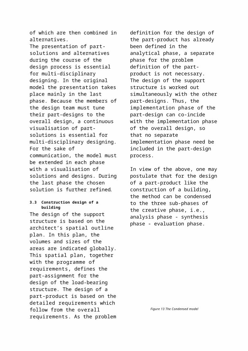
drawn then as desired in the appropriate material box. Alternatives may then be drawn and compared, and the total price calculated. Ordering lists may be generated and on-line sent to providers, who then on demand and just in time.a
The abstract description can also be the basis for defining the interface. Materials are also differing in the degree in which they can adapt themselves to their environment. That is why a product description is also needed.
4.12 Classification according to adaptabilityMany pre-fabricated products can not be adapted without damaging them unacceptably; think of pre-fabricated concrete or posts of doors and windows. These products are given the code P (part).
Figure 30 Part
Other products , like brick, wooden parts and planar materials are precisely used since they allow cutting or sawing on the building site, in order to make a measured fit. The products are given the code F (form).
Figure 31 Form
And then there are products delivered to the site as a material that will get final form
a Hartog, P. den (1996) NodeIT.
only following processing; like concrete poured on-site, cement, paint, foam and their likes. These products are given the code M (material).
Figure 32 Material
Earlier it was explained why it is that fabricating is better than building. In realising a building it is always necessary to build. A large share of pre-fabrication requires a lot of co-ordination, becoming more complicated with increasing numbers of suppliers. In the assembly of automobiles many suppliers are employed, but the location of production and the final product remain constant. In the assembly of buildings the site of production differs per building in terms of accessibility, and therefore of the providers. That is why the final product is different each time. In addition, different products demonstrate different sizing tolerances. For instance:
- a frame (P) in a pre-fabricated wall of concrete (P) must fit well; or it does not fit at all;
Figure 33 Fitting problem
- the brick work (F) surrounding a positioned frame is adapting itself readily and, therefore, requires less tuning in advance;
Figure 34 No fitting problem
- a wall decorated by carpentry must be sawn to size (F); - stucco and paint (M) always fit.
4.13 Position and adaptability combinedThe abstract description has a bearing on the space reservation for the material in a building. A distinction is made between the building (B), the space reservation for material: group (G), a subgroup; sector (S) and a tier, or layer in a group or sector (L).The product description concerns the degree of adaptability of a product and is expressed in part (P), form (F) and material (M).We can now assess the building according to the degree of building and fabricating, by confronting both descriptions in a matrix:
O V MBGSL
A traditionally built residence leads to the following distribution:
O V MBGS xL x x
Only the frames (sector level) have been pre-fabricated, made in the carpenter shop (P), the rest of the residence is on a low level (L) made on the building site (F, M).
A mobile home leads to the following distribution:
O V MB xG xSL
The entire building (B) is pre-fabricated (P) and is positioned on a pre-fabricated (P) foundation (G).
A building produced is traditionally focusing on the part of the matrix right bottom, a pre-fabricated building on the top to the right.
The abstract description enables us to link the space reservation for the materials to the performance requirements and to find the optimal product substitutes. When appropriate products have been found for the empty fields, this is as yet no guarantee for a sound building. In the case of building, as well as in the one of assembly, there are certain dependencies between the products found that should be examined further.
4.14 Dependency diagramsA building is a connected whole of building materials and building products. The connection transforms a collection of products and materials into a building that works. At the same time, the connection restricts the flexibility of the building, during construction as well as usage. A computer programme has been developed allowing analysis of the dependencies between various parts of the building. It can be provided in a dual way with building parts relating to one another, for instance: floor – door frame; frame door.aThe dependencies of a part of a residence have been pictured, by naming the building parts relating to one another dually.The building parts (equipped with their Part-, Form-, or Material quality) are, in the sequence of applying:
Bouwdeel O/V/M-code1 Systeemvloer b.g O2 Druklaag b.g. M3 Woningscheidende wand 1 M4 Woningscheidende wand 2 M5 Breedplaat verdiepingsvloer O6 Druklaag verdiepingsvloer Ma Kapteijns, J.H.M. (1997) Systematische
productontwikkeling voor de bouw.
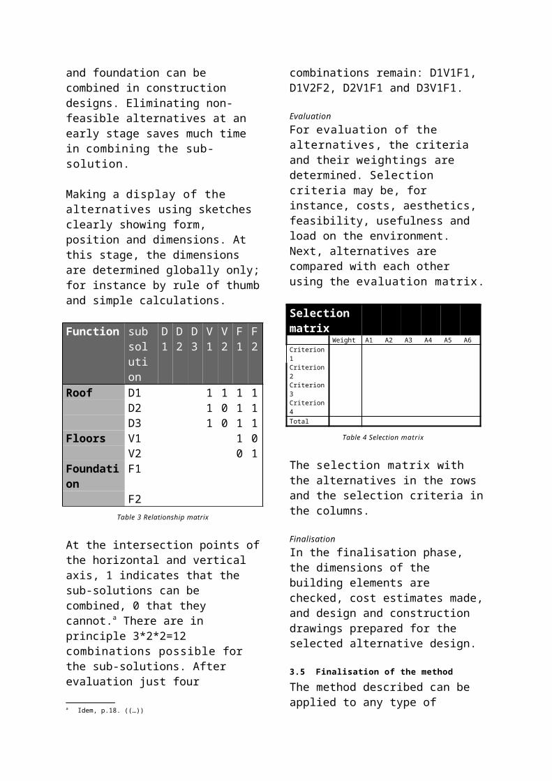
7 Prefab binnenspouwblad O8 Buitenspouwblad V9 Latei 1 O10 Latei 2 O11 Raamdorpelsteen 1 V12 Raamdorpelsteen 2 V13 Glas 1 O14 Glas 2 O15 Deur O16 Afwerkingsvloer b.g. M
Figure 35 Relation diagram 1
Now the relations may be ordered in different ways. In relation diagram 1 the building parts have been ordered in such a way, that the building part with the largest number of relations is on top, the one with the lowest at the bottom. This indicates the most critical part. This diagram gives a first impression of the various dependencies; a good point of departure for further analysis.
Figure 36 Relation diagram 2
Relation diagram 2 classifies the building parts according to their P/F/M quality. It shows all P-P relations. If long chains of Part – Part relations are occurring, this is sign of many pre-fabricated building parts, all of them with a dependency relation. Any change has consequences for all other building parts, since the change can not be transferred to any other part. If the chain
would be interrupted regularly with building parts with a Form- or Material quality, the ripple effect would be restricted significantly.
Figure 37 Relation diagram 3
Relation diagram 3 shows a hierarchical ordering: the same relations, now in clusters of connection. It demonstrates that the critical component forms the connection between two clusters, displaying per cluster just internal relations. Spotting these clusters may indicate independent product development. It could also be a reason for adjustment of the architectural design, in order to lower the number of connections of one cluster with the critical component; for instance from three dependencies to one. It will simplify co-ordination during execution. On top of that, it is an indication for simple replacement in the future. In the context it should be remarked that complicated relations restrict flexibility, while straight relations are not proving the opposite automatically. When the relation, for instance, is one of gravity, like in ‘floor resting on foundation’, this is an indication for the foundation as a subject for independent product development. This also means that during the design stage it is possible to change the foundation principle. It does not mean that the foundation may be readily changed by a different one following the transfer of the building to its owner.
Analysing dependencies is an important tool for assuring the flexibility called for: during the design, execution, as well as usage stage of a building. If we see a building as a system, a co-operating whole,
then the building node analysis is evoking the image of a building to be put together from various sub-systems, with a large amount of independence.
4.15 Classification as to productionThe dependency diagrams allow us to study and analyse the complexity of the connection of the parts. It is giving indications for clusters of components that may be developed as independent sub-systems, like carrying construction, façade, roof and interior facilities. This emancipation follows building practice, in which total sub-systems are pre-fabricated by a provider and applied in the works, with separate financial and guarantee arrangements.Next, within each sub-system a further sub-division can be made of fixed and variable elements, between frames and substitutes. In this way a roof panel may become a frame for a sequence of roof windows, extensions and ducts. Frame and substitutes are classifications of component ordering; possibly co-inciding with carrier and facilities, classifications of decision forming. The consumer buys or rents a home with a standard roof, but an extension to it of his personal choice.
Carrying structureThe carrying structure is the sub-system of the building maximally connected to the location. Residential building in The Netherlands is mainly made of concrete, blocks of limestone and brick. The nature of these materials sees to it that larger size tolerances can be reckoned with than for other sub-systems. In addition the carrying construction provides the context, the ‘frame’ for the other sub-systems.
Figure 38 skeleton
FaçadeThe façade has always been an sub-system, for which components (posts, windows, doors, bow-windows) were made in the carpenters’ shop, then carried to the site, ready to install. Within the sub-system frame a substitution may be distinguished. The substitutions may be of an architectural nature, like windows and doors, but also constructional, like motorised shading, shutters, mailboxes, electric doorbells with inter-com and security cameras.
Figure 39 Optional window
RoofThe laying of roofs has always been a separate profession. Roofs of thatch, slate, tiles and flat roof were provided by specialised sub-contractors. With the introduction of more extensive roof panels – the hinged roof being the largest among them – the manufacturing and applying of the sub-package is sub-contracted increasingly more often to suppliers. The roof is the framework for substitutes like windows, lighting surfaces, roof extensions and ducts for chimneys and ventilation.
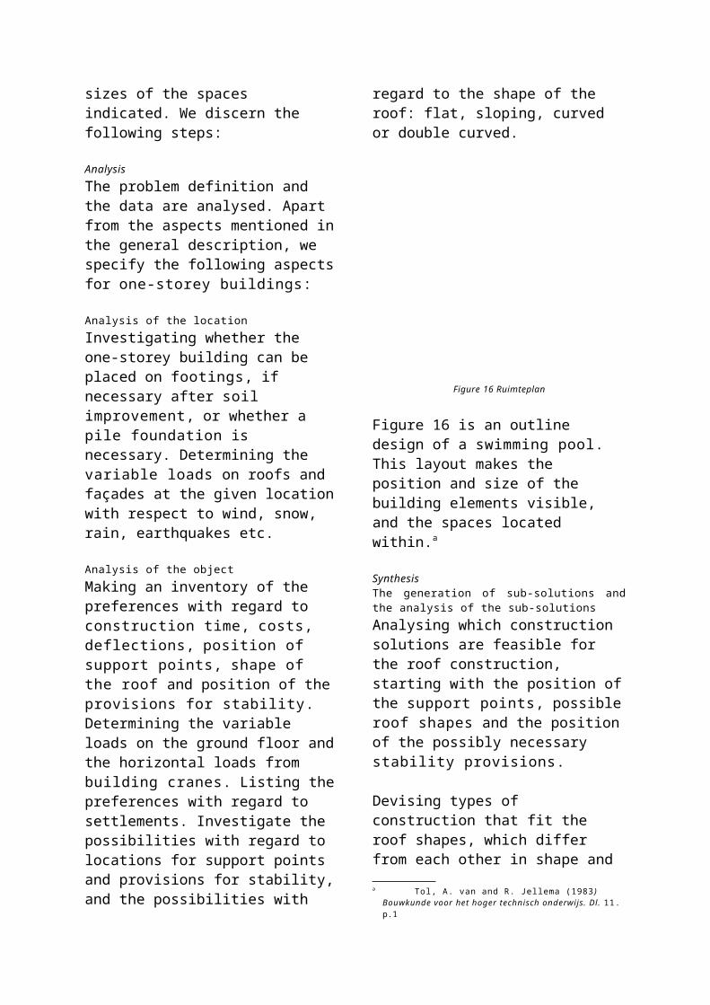
Figure 40 Roof extension
Appliances Appliances demonstrate the largest number of sub-contractors: plasterers, painters, tiling, plumbers, electricians. The main contractor always had an important co-ordinating task in this. The situation is slowly changing. Kitchen equipment, for instance, has vanished completed from building package and is sold now directly to consumers in the kitchen business, installing its wares without any interference from the main contractor. Appliances for bathrooms are being installed increasingly less often by traditional building partners; but ever more by specialists, approaching consumers directly. There is a clear trend that the whole area of appliances is becoming a constructional sub-system, installed by one agent in the glazed residence, without the interference of the contractor, and with bills directly charged to the consumer.
Figure 41 Matura system
The building node study demonstrated that the building part groups mentioned allow independence towards sub-systems. That this trend can already be discerned in building is not the consequence of the building node study, but of mutual
competition, the economic necessity to make a profit and of study following it.
The building industry finds itself on the eve of vast change. The residential shortage following WW II has been solved, the consumer has options as well as money. This means that the residential market is not determined any more by supply, but by demand. The consumer has power to buy; the building industry focusing on this has the best chance to make a profit and to survive. Building with frames, substitutes and independent sub-systems may provide an answer. In addition it is an important condition for independent development of building products; presently so advanced, that they cannot be developed any more for individual projects.Lengthening the life-span of buildings, dis-assembly for renewed use and ultimately separate processing for waste are three other reasons for building with sub-systems.Building node study is necessary, since it is not focusing primarily on improvement of the position of the building partners, but on flexibility of the building; finally on the built environment. The building industry understanding that is changing its bearings and will prevail.
5 METHODOLOGY AND COMPONENT DEVELOPMENT
Mick Eekhout
38.1 Products, systems and components.....30638.2 Developing is designing, studying and
managing in building..............................30638.3 Intuition, routine and method.................30638.4 Fundamental and applied studies.........30738.5 Types of designers.................................30738.6 Consuming and producing designers. . .30838.7 Profession profiles..................................30838.8 Design domains lacking R&D................30838.9 Pre-fabrication and co-ordination..........30938.10 Specialisation and co-operation............30938.11 A bridge between artist and engineer...31038.12 Architect and component designer.......31038.13 Registrating trains of thought................31038.14 Freeing methodology..............................31138.15 Methodical design approach..................31138.16 When is the methodical approach
inevitable?...............................................31138.17 Blob designs............................................31238.18 Permanent Quality Assurance...............313
This Chapter focusses on the methodology of component development, originating from 20 years experience in designing, researching and developing spatial structures and claddings for architecture by the author. Component development is the name of the entire process, which contains a continuous flow of designing activities, embedded in process management activities. Core designing is the main activity, reinforced and supported by researching activities. The process is bordered by commercial influences from the market, directed from and towards the client(s) on the one (demand) side and bordered by production-technical influences from and towards the producing industries on the other (supply) side. The process itself is directed towards the final material product. Marketing considerations are seen as a continuous reflection for the process leader: is the product in the making still the desired product? The entire development process is steered by strategic process management, ending in design quality assurance.a
a Eekhout, A.C.J.M. (1998) Ontwerpmethodologie.
5.1 Products, systems and componentsThe total process of component development is occupied by catering to the demand for new or renovated products. Three main groups can be discerned:
standard building products building systems or sub-systems special building components.
The initiative to the development process is found in the producer who wants to extend his product range with a new standard product (glass producer St. Gobain could develop, for instance, square, transparent double glass panels with the graphical effect of glass building blocks). Or, take the producer who wants to improve a building system for the construction market (like Trespa an over-cladding façade system for old office buildings); or an architect who wants to have developed, for his building especially, a set of components or even a project system (as Kees Spanjers did with a filigrain and hanging glass roof construction as an acoustic reflecting screen for the ‘New Church’ in The Hague).
The standard product, building system or special building component must be designed and developed in order to fit well in the larger whole of a product range, building system or building. From this technical application environment of building components, the boundary conditions are usually rather clearly determined by the totality of the building within which the product should function. That is why the process of product, system or component development can have a clear structure, certainly compared to an architectural design process. Examples of these process organisations are given on page Error: Reference source not found. Further in the text specific component development is referred to as the most interesting of the three main categories of products.
5.2 Developing is designing, studying and managing in building
Within the development process as a whole the design activities, in their inter-changing modes of analysis and synthesis, are relating to an increasing contraction of answers to the question, while research is used as an activity to fill in the gaps in knowledge. Research starts by finding out whether the knowledge lacking is accessible elsewhere (research and retrieval). If that is not the case, a quest must be undertaken to describe the unknown field effectively, in its characteristics and systematically, in order to discover general rules and laws to distill this way finally that specific part of the generally orientated new knowledge and insight into the application required.
Technical development should result in the development of the appropriate final product, via a trajectory in which a solution is found for all sub-problems: either by designing or studying. In this, technical designing is the widely ranging and continuing composing of elements and components with known and unknown characteristics. Technical study is busying itself thoroughly with one, or few, technical aspects at the same time; in principle a finite activity. Process management is the continuing care for progress of the total development process.
5.3 Intuition, routine and methodThe development process as a whole is, all things considered, extremely complex. The entire scholarly development process is developed in all parts critically and consciously. In comparison the practical development process (in the practice of design studios) will fall back in many points on routine knowledge & insight or intuitive decisions, carrying the process some distance further on the basis of a well developed feeling; or just good luck. This applies, while usually the novelty is only designed and studied on a select number of striking aspects. It is not necessary to re-invent the wheel all the
time. The building technical designer will do his best to tackle each new design challenge with the originality and the ingenuity needed (from which novelty emerges), given his knowledge, insight & experience. Because of marketing influences, special component development as a total process is always application orientated; since a useful standard product, a building system, or a special building component should result.
Figure 42 Schematic Process
In the design flow (design nucleus) considerations without a technical or application nature may also play a rôle; for instance social and cultural considerations.
5.4 Fundamental and applied studiesThe partial studies needed for the development process may be fundamental or applied. For the Quattro frameless double glazes panes, Octactube developed in 1995 a chemical glue connection which does not enter the space between the layers. In co-operation with the Faculty of Aircraft Building this study of glueing was conducted as fundamental study; since a visible UV resistant glue had never been realised before. At the same time an application study was undertaken in the form of shortened long duration experiments in order to be able to give the conventional life-span guarantee. The development process as a whole, of which both types of study were parts, resulted in taking out a patent and dozens of applications per annum world-wide.
However, the timing and the rhythm of applied and fundamental activities in a process of development are quite different; as gears with different tooth-wheels. For the new office building of Zwitserleven Headquarters, designed by Pi de Bruin in 1996, 5 glass ‘louvre’ beams were foreseen above the main entry of the building spanning 23 and 27 metres with a height of 25 m. More than 80% of the building budget was spent on this study. Project constructor ABT and producer Octatube were strongly divided in their opinions on the built-in security of the design, resulting in a long series of prototypes and tests. This was fundamental study: nowhere else in the world had a 27 m long, free, spanning beam made from glass been realised that could carry its own weight through the glass alone. The project was terminated one year following the opening of the building, with for an attained performance of a breaking strength of some 60% of the stress aimed at in the glass construction. Measured in intensity as well as in time, this fundamental process of component development did not match the ongoing building process.
5.5 Types of designersJust as this book as a whole, the present Chapter addresses three types of designers. Each of them will read it in a different way, for only after some (negative) experiences will the necessity be felt:
Young designers (students), in need of a lot of knowledge, insight and experience. The methodological aspect should be emphasised in design education more strongly than presently. Many students think that the block and module manuals are their methods. During the graduation stage – when they have to function completely independently for the first time – many students demonstrate total absence of methodological insight.

Professionals in design studios with knowledge, experience and insight who are tackling each design task from routine, often with an intuition nourished by experience. The efficiency required and the time-pressureusually characteristic for the design process is leading to leaps in the decision process of the designing guided by experience. Professionals should break with their routine & intuition and make them transparent, in order to give students a scholarly and educational design insight. For students the author wrote the book ‘POPO or design methods for building products and components’.a
Scholarly developers, designers and students, monitoring a development process in order to come for a new task to a new solution by means of new materials and systems, thus increasing the state-of-the-artof the technology. In the Faculty of Architecture Dr. Ir. Karel Vollers is a striking example of these scholarly component designers. February 6, 2001 he received cum laude his doctorate for his dissertation ‘Twist & Build’ on façades demonstrating torsion. Its subject encompassed urban architecture, architecture, building technology production technology and material science; and back again: Design study and study by design (see also Chapter Error: Reference source notfound on page Error: Reference source notfound).
5.6 Consuming and producing designersIn the praxis of architectural designing novelty is often found exclusively in the composition of building components into a new spatial whole: ‘designing as composing’. Well-known architects like Jan Benthem and Mels Crouwel act mainly as building consumers on the building market and are composing their buildings from elements and components offered on the market. Their studio is hardly active in product development, if at all; in component development in the construction parts of their buildings. Completely opposite in the spectrum, Jan Brouwer always devoted a lot of attention in his work to development of new and original components. He is behaving as a designer-producer in the preparatory stage of building. The rough polyester ‘Brouwer’ façades of the eighties are an example. He seduced the producing industry into co-operating with him. These components and a Eekhout, A.C.J.M. (1997) POPO of ontwerpen voor
bouwproducten en bouwcomponenten.
their combination with components of a different type endowed the buildings of Brouwer of that period with a strong identity.
If the architect is unable to produce a new or original composition with well-know components – or is not allowed to; as is often the case in residential building with its low budgets – the degree of originality of the designing is almost lowered to the level of engineering. That does not require (scholarly trained) designers, but engineers. The Faculty of Architecture does not choose to educate its designers in that domain. Architectural designers should produce original and sophisticated work. The degree of originality of a design determines its quality greatly. It also happens that deliberate eccentricity of architects to produce compositions in an opposite way than the usual one is responsible for the quality of their designs; like the ‘ruffled’ buildings of Ben van Berkel during the nineties, and the new generation of ‘Blob’ architects (later in this Chapter).
In the praxis of design studios study, making the unknown known, is usually conducted from a personal shortage of knowledge and insight. This often amounts to acquisition of lacking knowledge and insight that is known elsewhere; or supposed to be. Rather, finding out and retrieving along these lines involves investigation (things unknown to the student only). It has nothing to do with ‘scholarly study’ increasing world-wide the state-of-the-art of technology that is the subject of this book.
5.7 Profession profilesSo, within the whole process of component development, many designers in the building construction industry excercise a combination of activities in the field of development, design, research, engineering and management. Engineering is understood as the full elaboration of a
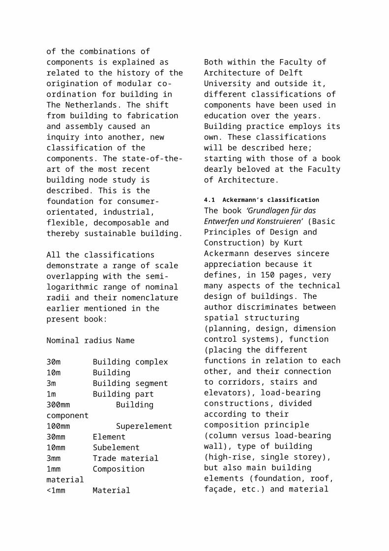
building component once all design and research decisions have been taken. Engineering of components is often very critical as mistakes may cause dis-efficiencies or even failures. However, inseparable from the design and research activities, engineering in essence is not a core activity in the eyes of the scientific designer. In most technical development processes design, research, engineering and management are integrated to a certain degree, however the emphasis may differ between different component development processes. Emphasising one type of activity does not exclude another. Nevertheless, they are distinct enough to form the basis for three separate profession profiles of the Delft University Master of Science (at this moment still called ‘technical engineer’).a
the Master of Science as a designer; the Master of Science as a researcher; the Master of Science as a technical
manager.
Figure 43 Three profiles overlapping
In the praxis of building the three profiles will always overlap. The student should have mastered the three profiles as fundamental qualifications. The professional designer should be able to deal with the three profiles as a partner; and when he has but a small office, he should integrate them in his own functioning. The scholarly designer knows how to separate the three profiles clearly and get them into dialogue.
5.8 Design domains lacking R&DIn architecture three principally different design domains may be distinguished: city-building, architecture and building technology. On each level, but certainly in building technology, building is distinct from other engineering disciplines by:
a ARTB (1995) ((…))
Extensive dependency on context; Multi-disciplinary complexity of the
design task; Cultural sensitivity of the result; Providing for one of the basic human
needs; Well-known and generally used, often
simple methods of execution; Relatively low-valued or traditional
materials; Low entrance level for players; Small-scale of the enterprises concerned; Fierce competitiveness between
designers and producers as well as builders; low prices for components;
Relatively low final product costs; Strong focus on straight applications
and absence of a feeling for long-term developments;
Lack of a profound tradition and attitude in studying.
These properties are resulting in a shallowness of fundamental as well as of applied study. Generally, design activities are not regarded as study. Generally, the energy put into the development of the design during the preparatory process of buildings – in the form of designing, study and engineering – is not seen as ‘Research & Development’. The engineering is almost completely application orientated. The bulk of the activities mentioned is charged directly to the projects. However, from the project-driven activity of building the experience & insight from the developmental processes is remaining. The study of SMO indicates that in building (= civil engineering + architecture) a meagre 0,5% of gross income is spent on R & D.b Water engineering is taking the largest part of that pie. However, in the case of buildings 10 to 20 % of the execution value is spent on development, design, research and engineering; being the total sum of the wages of the architect, advisors and engineering departments of the producers. With the total sum for R & D in building there can not be too much amiss. But, the b Jacobs, D., J. Kuijper et al. (1992) De economische
kracht van de bouw, noodzaak van een culturele trendbreuk.
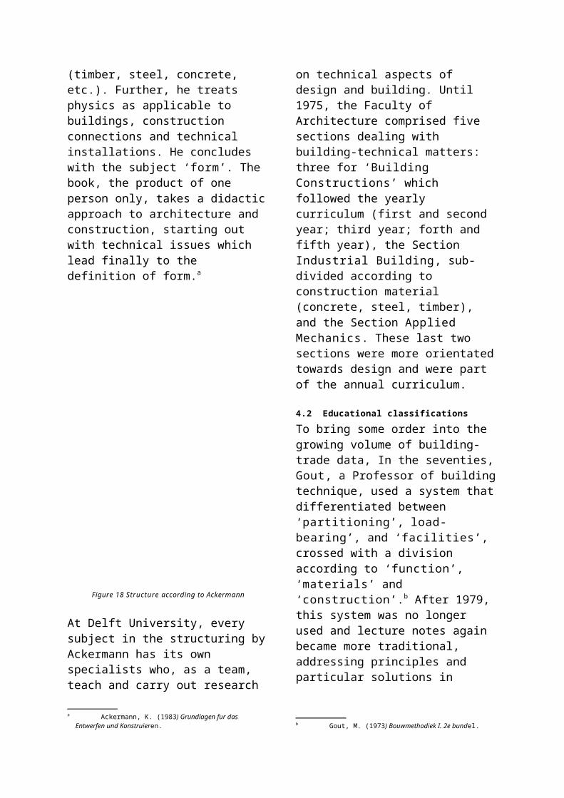
long-term fundamental R & D is missing; usually it is application orientated on the very-short-term.
5.9 Pre-fabrication and co-ordinationWith the increasing complexity of buildings enabled by the more constructional character of the components and by the freedom vis-à-vis the Cartesian grid, in which architects can indulge through computers (see the ‘Blobs’ later); the process of preparation itself is also becoming very complex. It is requiring a process management based on thorough insight into all aspects of the development of a building design. Until two decades ago the architect was, traditionally and technically, the hub in the developmental process of building. This position is being eroded since then. However, computer-orientated preparatory processes could result in a watershed. In the new developmental processes for ‘Blobs’ the process is dominated by agreements between the chief designer and part-designers (engineers or co-makers) on the basis of the spatial 3D model, produced, certified and guarded by the architect. Out of this he can distil a position of power, as long as he shoulders the burden of the associated responsibilities for correctness of the geometry of the whole building as well as its parts.
Figure 44 Part 3D model of the Floriade design by Kas Oosterhuis
The realisation of building in open air with heavy materials and large components has very few, or no similarities with the increasingly virtual world in other branches of enterprise. Young people are clearly becoming more hesitant to start working in the building industry. The labour conditions prevailing at the building location are improving more slowly than the inclination of youngsters to become subjected to the slings and arrows of the outdoor climate. Quality control on the site is also leaving a lot to be desired.
Components manufactured in a well-equipped production environment are featuring a better quality. The character of building will be determined increasingly by industrially fabricated standard building components and building components and building systems requiring much more co-ordination and integration for the various engineering disciplines, the productions of components of dozens of producers and the final assemblage/ execution in each building project. The preparatory process is becoming much more technical. In the past this task of co-ordination had to be executed by the chief constructor. Presently the number of constructors well aware of technical specialities is very limited. That is why specialised building managers are coming to the fore increasingly in order to take over that function. On the long-term they can only be successful in this, if they are having sufficient technical insight and willing to take a proportional part of the risk for their co-ordination.
5.10 Specialisation and co-operationThe environment of the technical designer is determined to a great extent by the one of the architect. The competition among architects operating independent from production & execution is fierce, because of the large number of relatively small studios. More than 75% of Dutch architectural studios employ less than three people, with a modest turn-over per person. A completed education, a position in the register of Dutch architects, a number of relatives in the building industry, or winning a design competition prize, and one or more design computers are providing a starting architect already with the wherewithal to compete. Next, architects are inclined to develop and work out further all kinds of, and increasingly differing types of, design tasks. Shared sub-contracting to specialised colleagues is almost non-existent. Specialities in a segment of the building market are occurring mainly in larger studios; for instance with EGM, with many hospitals in
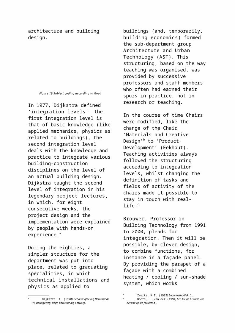
its design portfolio, and NACO, developing many airports.
As a buying market building is usually local and the players are national; some engineering agencies and starring architects are operating internationally as an exception. Ambitious authorities on the city-level tend to profile themselves occasionally by proposing international design competitions. Some major international building companies and producers operate in several countries as well; however, again, according to national rules and with national networks. The regulation is still not very internationalised, due to informal national protective constructions; although there is a striving towards a clear European or international standard.
In building, technical designing is orientated towards application. In the easily accessed building industry it is customary to work with ingredients well known, understood and manageable by designers, as well as producers and constructors. A musical composer designing for each part in the score for his concert new notations and musical instruments will not perform many concerts. Too much attention for application and engineering, however, can cause in its turn undervaluing fundamentally new possibilities. Fundamental (applied) study is in that case insufficiently conducted; and designs are chosen from well-known materials, techniques and components: putting together, rather than inventing. This picture tallies with the majority of present building. Scholarly designers should be able to change this with a higher ambition
5.11 A bridge between artist and engineerAn architectural design requires so many design decisions with complex inter-actions, that most of them will be taken by routine or intuition. A methodical approach is only serving to make this intuition clear to young designers and to the
professionals in order to bridle them in some design tasks. The design capability of the architect finds itself somewhere in between the extremes of the functional-technically developing engineer and the purely intuitively shaping artist. The engineer with his rational thought and the sensitive artist – that is technique and creating form – are constituting the extremes of the band-width within which the architect is looking for his place. It should be kept in mind that both extremes do not exist without their mutual influence; a work of art can not stand on its own feet without knowledge of materials and technique of construction. At the other side of the fence, in the development of bridges in the Netherlands designers are becoming increasingly involved, in order to give the concatenated techniques and sub-systems a face that may be recognised. Luckily, there are also heroes in the building praxis serving as beacons for combining art and technology. Renzo Piano is making gorgeous buildings, earning each time respect by their originality as architectonic concepts (the KPN building in Rotterdam was built for a normal square metre price) while his chosen materials, components and details are managing the same feat in the technical working-out. Next to this, Piano is the most striking example of the studying designer developing his buildings in an innovative and inspiring way.
5.12 Architect and component designerThe architect finds himself between the urban designer and the component designer. At one side, social and cultural considerations are usually of importance, at the other functional, technical and economical ones. In this he must maintain the creation of form as a characteristic of his position as an artist and of the building as a form of applied art. The position of project architect, on one side, and of component designer, on the other, are usually distinct in the design band-width, in spite of the inspiring example of Renzo Piano. The component designer, who
might be employed by an architect as well as by a producer, will have a tendency to the rational engineering approach, but with a high architectonic ambition level. The book by Roozenburg en Eekels: ‘Product design, structure and methods’ is influential in this respect: not only used at the sub-faculty Industrial Design of Delft Technical University, but also frequently in the building technology curriculum of the Faculty of Architecture.a
The component designer serving the project architect is, as a consumer of building products offered on the construction market and respectively of building components developed previously by third parties, rather less restricted to existing techniques of production and materials than the producer bound component designer. He is aware of the luxury of choosing from many more possibilities: also from possibilities seldom used or those that have to be imported in the discipline. As a designer-consumer he is not obliged to employ certain ways of producing or executing. Firstly he will be trying to get his personal ideas for components realised. Secondly, if that proves to be too expensive, or impossible on other grounds, he may opt for a higher degree of individuality for the total design through an unconventional ordering in the space (‘topology’) of standard products and system components. He has more affinity with the approach of the aesthetic composer. Standard components may also be used in an improper, or new way. Rudy Uittenbroek designed on Eindhoven University campus buildings with non-rectangular bricks. The eccentricity of the project architect can result in an eccentric building, realised in spite of a small budget by relatively few economical means.
The difference in the approach of the engineer and the one of the designer is the
a Roozenburg, N.F.M. and J. Eekels (1991) Produktontwerpen, structuur en methoden. English translation: Roozenburg, N.F.M. and J. Eekels (1995) Product design, fundamentals and methods.
continuing combining of analysis and synthesis and feed-back between the two, if intermediary results are not satisfactory. The engineering approach, related to the methodology of designing, is resulting not infrequently in a straightforward technical-functional motivation with the appropriate feed-back. Contrariwise the designer approach results in a one-of-a-kind creative-aesthetic motivation.
5.13 Registrating trains of thoughtThe integration of functioning as engineer and designer is very suitable for the developmental process of the component designer; when combined with a periodical description in writing of trains of thought and results. The ease with which meticulously recorded design processes can give insight to outsiders is at the same time a good start for convincing the commissioner.
To the designer it makes a lot of sense to be able to verify his own reasoning and to weigh the mass and validity of the arguments once more, especially for feed-back and evaluation ex post; but also to reserve room and to create expectations for creative explosions or implosions! During the development process creativity should stay well-protected. Still, working systematically and recording it often results in a better controlled design process. Fortunately, excellent examples of this way of working may be found among distinguished Dutch architects. In their publications on architecture both Herman Herzberger and Hans Ruyssenaars demonstrate this transparent, but inquisitive approach. Especially in case several processes must be going on simultaneously within the head of one designer – something often happening in a major design studio – chronological reporting and accounting is an excellent tool to maintain insight into the design process. All too often a talented designer is faced by dozens of projects on his desk. That requires adequate ordering. ‘Simultaneous
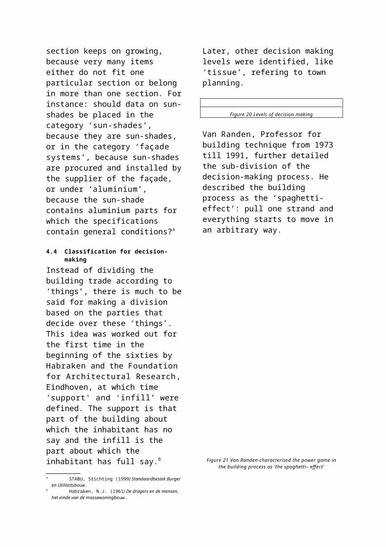
designing’ may be compared to playing simultaneous chess .
5.14 Freeing methodologyFor building technology developers applies the dictum:: designing is an efficient process in making decisions towards an original, ingenious, functional, material and spatial solution for a construction problem, from initiative to realisation.a
Methodology is the science of methods used in a process; component design methodology applies to the theory of methods for component design.
Methodics is a set of methods somebody or a group of professionals operates with; in this case the set of methods used by a building engineer or a group of professionals during the component design process.
A method is a fixed and well-described procedure. A component design method is used during component development and designing. Some methods cover the complete process: ‘overall’ or complete methods. However, most methods are partial methods, only applicable to specific parts of the design process. An overall method can contain several partial methods.
The word ‘method’ is derived from the Greek and means ‘the way between’, between the beginning and the end of a reasoning, between starting-point and objective. In linguistic usage it became understood as: the way, an absolute datum. That is somewhat inherent to the fact that a method seems a fixed, well-described procedure. Therefore, an individual method also has to be well-described, in order to avoid the predicate ‘arbitrary’.
So, a personal interpretation of a design method always remains possible. There is the restriction, that it must meet the general demands of methodology; that the different steps or activities must be explicitly a Eekhout, A.C.J.M. (1997) POPO of ontwerpen voor
bouwproducten en bouwcomponenten.
formulated and that they are open to communication, control and verification by outsiders, by tutors for students and by building team members for clients.
Although methods are generally used in practicing research science, in designing, on the other hand, opinions on the sense of using methods are divided. There are two extremes: the intuitive and the methodical approach. The routine approach is unconsciously methodical and lies in-between. In general successful design processes occur with an approach that can lead to good design results.
5.15 Methodical design approachThe self-directedness or conceit of the designer does have to make space for directed, fixed and well-described methodics. The other way around, next to methodics there has to be kept a clear space in the design process for the individual creative ideas which make design results often so self-willed and attractive. Methodics must never suffocate originality. On the other hand, ‘methodical’ designers in their searching process of designing try to apply systematics and methodics which, from previous experiences, give them greater security for success. It is not so much the kernel of designing, the brainwave, where the looseness of thinking and creativity plays a grand part, which can be improved under the influence of a design method. But, to be treated methodically is the introduction up to the growing towards that creative moment (because with that, one is sure to be busy with the right design commission) and the following complete working-out (materialising, detailing and evaluation). Every human being has certain systematics built in his ways of thinking and acting, usually unconscious, but sometimes by force explicit and extrovert. Thanks to the fact that these systematics determine our actions unconsciously, we can spend more energy on outstanding and decisive moments.
For students, moreover, it goes that acquiring designing as a skill can give more insight when done systematically, in a discussible manner. Because of this, methodology will bring about a faster learning process for young designers. That communicative function also belongs to methodical designing and written reaction on it later: it advances the identification of parties around the designer, with the interim and definite process result, and it makes a sensible and effective reaction possible. A designer beginning will be insecure whether (s)he is capable of accomplishing a design. Intuitive trying has the advantage of aim and shoot: it will miss often at first, and, hopefully, it will gradually score a hit. When an inexperienced designer has made a design strategy on his own, through methods and practice, gradually a relaxation in his head comes about, that there will always be a solution as long as he works methodically. But, at certain points in the methodical design there has to be room for the spark, the intuitive design idea.
5.16 When is the methodical approach inevitable?
The described view on designing and developing originates from experience with the designing of building components and of buildings. Small, repetitive or surveyable designs are often fed by unconscious knowledge and skill in an acquired routine of previous design processes, whether or not they were realised. Routine designing as a subject is not interesting, compared to the design process where the various steps and activities are done consciously and methodically. It takes place mainly in the same manner, only many times faster and undescribed. But, it cannot be denied that routine designing also has its origin in the methodically and extrovertly made design process, which by repetition and routine can be carried through at much higher speed. However, routine designing becomes a problem to the building engineer when the
two qualities of the design ‘ingenious’ and ‘original’ disappear. The form of the design process, however, is isolated from the ingenious and original contents. For design orders with new challenges which rise above routine, the use of design methods is very sensible. Especially when one or more of the following non-routine characteristics in the design problem are valid. It is extremely sensible to use a method which can be controlled with a potential for communication on the design process and the design itself:
New design problems Advanced design problems Complex design problems Experimental design problems Ultra-fast or fast-track design problems
With new design problems the newness can, indeed, be found in one of the following characteristics. But what is meant is a design order totally new to the designer, or outside his experience (for a building designer, for instance, a ship’s interior), or before his experience (to a young designer, who is yet inexperienced in the field of designing). Students have to learn methodical designing before they give it a place in their personal design approach: intuitive, routine-wise, methodical and yet typical, diversity, combined or integrated, whereby intuition and method chase each other to get better results.
With advanced design problems it is often sensible to divide the complete process systematically in different parts and to develop these parts simultaneously: ‘concurrent designing & engineering’, whereby the necessary methodical approach, resulting in drawings and reports, makes the mutual communication about the different interim results possible. The partial designs are afterwards integrated into a complete design.
In the case of complex design problems with mutual influence of aspects, these orders are often divided into smaller parts or aspects: each of them better surveyable
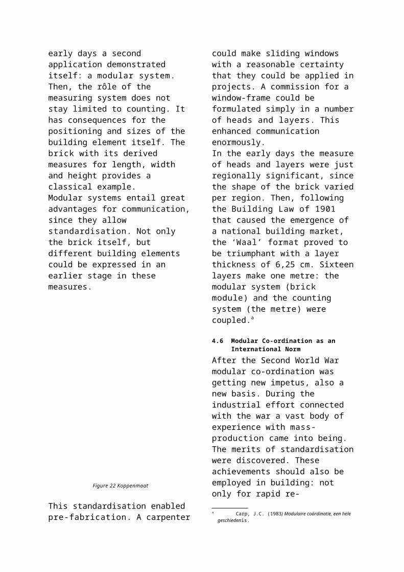
and solvable, after which an integration is made of the part-designs into a complete design. The integration is more complex than the assembly. This working sequence is a method in itself. Methodical designing may take place completely in an all-enfolding schedule, as in the organogram, but it can also manifest itself very simply as an ad hoc agglomerate of smaller partial methods. This entails that in certain phases of the design process a scheme in abstraction is made of various activities to be undertaken, whereby especially the sequence and influence is graphically described: very often small scribbles, immediately understood by spatially and visually thinking designers. As a means of communication, visual schemes are very effective in the profession.
With experimental design problems there is a high degree of technical uncertainty. The designer must operate carefully in order not to overlook important matter and so reduce the chance that the final design does not meet all essential aspects. Experimental design orders are characterised by great contributions from research. In the experimental design process verification is important for communication and determination.
The ultra-fast or fast-track design process has to be worked through in an incomparably short time. The chances are big that the design will be done completely on the automatic pilot. There will be no time for studying extensive alternatives. A course of solution has to be chosen by feel or experience. It is then a challenge to choose a surprising course, not a well-known one which will lead to an expected result. The complete design process, which in other cases can be worked through step by step, has now to be worked through in ‘less time’. Then the skill to make the right decisions is brought up from previous choices (experience) and not to work through an impoverished design process with less design variants and therefore a
smaller chance on a good result (creativity). Often this type of design process leads to ‘concurrent engineering’; with the danger that cause and effect do not connect anymore: sometimes there is already an effect while the cause has yet to be developed. Then the designers find themselves all mixed up. They confuse result with objective, while in the mean time the evaluation criteria are silently shifted. A high level of alertness and steering is required. The design method supplies the basic framework for internal communication.
5.17 Blob designsAn illustrative example of design processes where methodical approaches are wanted, are ‘Blob’ designs: designs of buildings without straight lines and flat façades, except the floors (also called ‘Fluid Architecture’). The most illustrative examble is the Bilbao Guggenheim Museum designed by Frank Gehry. The origin is older. Archigram designed fluid building envelopes in the sixties. Only after development of 3D designer computer programs able to prescribe the geometry of curved surfaces accurately, fluid architecture became more popular. In spring 2001 the Department of Building Technology formed a special ‘Blob’ design research group to bridge the gap between designing and computing architects and the desperate industry, confronted with the task of producing 3D curved surfaces in all sorts of materials architects think of these days. Apart from the inspiring, no doubt expensive building designs of Gehry in the USA, Spain and Germany, Dutch architects lead the trail, like Kas Oosterhuis, Lars Spuijbroek and Erick van Egeraat. But, Norman Foster is also constructing in London two ‘Blob’ designs: the egg-shaped Greater London City Council building near Tower bridge and the corncob-formed Swiss Re high rise building, also in London; Ove Arup is occupied with a wild sculptural roof over the shopping area Chavasse Park in Liverpool; and so on. A
high-profile building is the town hall of Alphen aan de Rijn, designed by van Egeraat, one year under construction. The 2002 Floriade exhibition will house several ‘Blob’ designs. One of these is the provincial pavilion, designed by Oosterhuis. Its form resembles a giant rock, made in a single layered triangulated space frame, covered with 3D curved aluminium panels in triangular form; all panels and space frame elements to be individual: ‘Industrialisation in lots of one’.
Firstly, this building poses a new problem for the building technical designer. Secondly, the gap between the designer’s computer programme and the producer’s programmes is large and seems unbridgeable. Thirdly, the design is complex because of the extreme individualisation of the components. Fourthly, it is heavily experimental because all the triangulated panels have different bending radii and should form a flush surface, once mounted together. Fifthly, the opening of the pavilion is contracted, by the building technical way is uncertain. Yet it is an extreme challenge to perform an extensive process of development, which should increase the level of technology dramatically. At the moment of writing the process is still uncertain, but only with the utmost of carefulness and described in an methododical approach, can the target be achieved. De Delft ‘Blob’ design & research group is heavily involved on many levels and with many different specialisations to get this ‘mission impossible’ on the road. 5.18 Permanent Quality AssuranceParallel to experiences in the car industry, in building practice the notion also slowly dawned that to notice and remove already made mistakes only at the final check (= design assessment), is not very efficient. Especially when mistakes are immediately punished by the consumer. Avoiding mistakes is of the greatest importance. A car has to be, in principle, a ‘zero-defect
product’, achieved by a continuous quality control in the entire production process, not just by probation periods after its final production. As a backing for intuitive building designers goes that the assessment criteria are not unanimous to the consumer. Moreover, defects in building practice are not so often critical and/or measurable (with the exceptions of leakage and draught, although they are looked upon as execution mistakes, not often as designing mistakes). Up to the usage phase one can always tinker with the design and technical applications to achieve a better performance. The relatively poor level of design and research and quality assurance of the prototyping building industry results in the questionable quality of the buildings realised.
A bold example is the sunshade and daylight regulation system to be applied after completion in the clear glass façades of the office building of the Netherlands Architecture Institute (NAI) in Rotterdam, designed by Jo Coenen. All parties involved knew about the ‘greenhouse’ problem of these façades, in practice it is actually in-operable, but even for this very important architectonical monument, there was no budget being made free during the building process. It is an example of the low-technological characteristic of the building industry, as opposed to a more industrial aspiration of the ‘Blob’ approach.
At the same time lack of clear assessment criteria leads to continuance of an essentially wrong procedure: by the grace of ignorance, minority or matchlessness, the design result is accepted as it is presented. It does not lead to a higher quality in the view of the consumer. How long can designers get away with this quality level of results?
The car industry formulated a first answer to this in the Sixties with the TQA (Total Quality Assurance) and points to the
process being controlled continuously, as opposed to the only and too late final check of the assembled car during a test-run.
This process quality control is the basis of the notion ‘quality guarantee’ for the material realisation of buildings and building components by the industry. The design quality is achieved by, first of all, communicable development processes. In the routine of proper component and product development it could be followed by quality manuals, eventually possibly leading to certification. If the minimum criteria are determined, control is indeed also possible. But, what to do when the quality criteria are not, or hardly determined? It would be better to strive avoiding that the designer fools himself, as well as his client and the consumer by great uncertainty as framed in the notion ‘black box design’ and to achieve that he looks upon his design methods as a ‘glass box design’. There has to be at the start of every design process, among other things, the fixing of the evaluation criteria of the design result. After this the quality of the product, system or component can be assessed or measured continuously. Then intervention is possible when insufficient interim results are noticed. This mechanism of feedback also proves to be a good help with attending to graduates during their design processes.
In the process of development of ‘Blob’ designs an overall quality assurance plan is the only one that ensures an overall quality. This means that all parties involved: client, architect, structural engineer, climate engineer, advisors, main contractor and specialist sub-contractors all have to play their part in the quality assurance plan, from the beginning preparation of the project up to the completion of the building. The omission of one party playing its rôle properly for himself and the others involved can cause considerable damage in the process. The results can be abortion of the entire project,
overexpenditure by the client, bankruptcy of producers and contractor. All these results contribute to the premature demise of a highly exciting and promising new line of architecture.
Quality assurance is the ultimate expression of openness in performed activities, of a methodological approach, which is not a scientific topic any more, but a social necessity, if new and exciting trends in architecture like ‘Blobs’ are given a chance in balanced conditions.
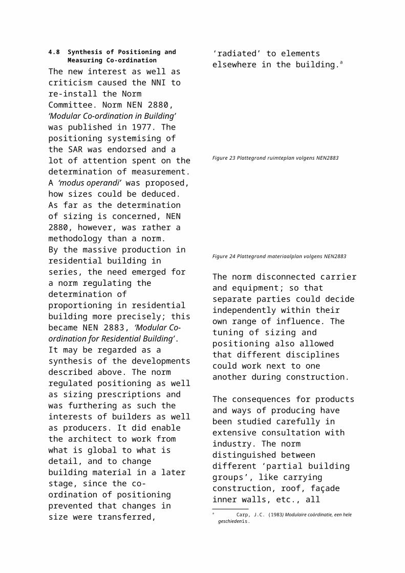
6 INDUSTRIAL DESIGN METHODS
Alex Jager
39.1 Industrial product and architecture.......31539.2 Product development.............................31639.3 Designing products.................................31839.4 Designing architecture...........................31939.5 The product developer as a product
enterprise................................................32139.6 Difference in policy and strategy...........32139.7 Looking for possibilities..........................32139.8 Idea analysis...........................................32239.9 Idea definition.........................................32239.10 Cross-fertilisation....................................322
Design methods for industrial products and methods for architectural designing do have similarities as well as dissimilarities. This Chapter is comparing the process and the players to one another on the basis of the differences between an industrial product and architecture.
6.1 Industrial product and architectureAn industrial product is a commodity invented, made, exchanged and used by people because of the properties it features and the functions it may serve.Although the word ‘product’ can refer to everything brought forward, in the present Chapter it relates to objects for utilisation like razors, telephones, washing machines, and so forth. According to Roozenburg and Eekelsa these products share a number of characteristics between themselves:
They are material artefacts: they are visible and can be touched;
they are fabricated: they are made from materials and half-fabricated components;
they are discrete entities: the products intended function independently and when they are functioning the whole product is involved;
they are end-products: their intention does not pre-suppose additional processing.
‘Architecture’ is, in the present Chapter, the result of an architectonic design process.Methodological differences between the design process of an industrial product and
a Roozenburg, N.F.M. and J. Eekels (1998) Productontwerpen, structuur en methoden, 2nd ed. English translation of the 1st ed.: Roozenburg, N.F.M. and J. Eekels (1995) Product design, fundamentals and methods.
the design process of architecture may be better understood on the basis of differences between an industrial product and architecture. There are differences in:
multi-functionality duration of life-cycle robustness dependence on location scale spatial experiencing personal ties
Multi-functionalityThe first and most important difference between an industrial product and architecture is that a product is a mono-functional (or oligo-functionalb) object of use, while architecture has a great many functions. The number of functions depends on the number of objectives to be accommodated by the result.Compared to the designing of products, architecture is taking a relatively long time for designing and must keep complying with new requirements. Therefore, it is more difficult to give a precise description of all objectives.
Figure 45 Architecture designing and product designing
In the figure above a number of (sub-)components forms a certain product. That product serves one or more clearly described objectives. The case that certain objectives are not striven at may also apply.
b ‘Oligos’is Greek for ‘a little’: a product is oligo-functional when it has but a few functions.
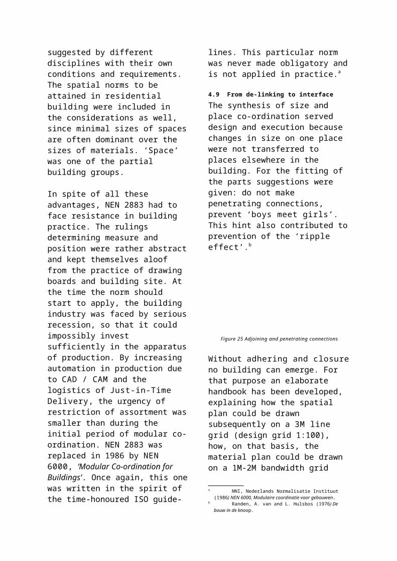
Together these products form the architectural product. Actually these products have become this way (sub-)components. Architecture originated this way strives, in its turn, at a large number of objectives. This number is larger than the sum of the objectives of the (sub-)components. Adaptability in the course of time might be an additional objective, as well as flexibility, comfort, experiencing aesthetics, etc.
Duration of life-cycleNeither industrial products, nor architecture share in eternal life. After a certain time a product disappears from the market: be it, while a better product catering for the same need has been introduced or be it that the need is vanishing. In the life-cycle of a product a moment may come that the product is successful. As from that moment on competition will raise its head. This competitive battle causes lowering of the price of the product. If the product can not be made cost-effectively, the end of its life-cycle will come.A need is spotted by scrutinising the market. It is even possible to create a need.
For architecture this is different. The need of the consumer on the real-estate market is clear: an affordable, spacious and, preferably, detached home with a garage. Three out of four people want to live ‘in the country’. Contractors, architects, suppliers and project development would rather cater for that demand than do anything else, but the market is not exclusively dertermined by the consumers and those market parties: more than half of all homes is rented. The prime need in housing is timeless, enduring and continuous, but also more pluriform than in most other products. Simply put: almost every one wants a roof over his head.The life-cycle of architecture is being shortened: where previously buildings were begin constructed for ‘eternity’ are now buildings rising in order to be ripe for
demolition within forty years (or eighty in the case of housing). Because of the quick succession of social, economical and technological changes the secondary needs associated with the primary need will change as well.
RobustnessA consumer buys a product as it looks at that moment. The consumer does not expect that the product is adaptable in such a way that it will continue to serve new needs. Since most products are not adaptable, there is no necessity to include functional flexibility in designing considerations. This has to do with the relatively short life-cycle and low cost price of a product: at a given moment the product ceases to satisfy; a new product is purchased serving the same need better. In this, trends play a rôle: if a product is no longer ‘in’, some groups in the market will start to purchase a product catering for the same need, but shaped and formed according to more recent types of insight.In the case of an architecture product, users expect that it can continue to cater for individual and changing needs.Real-estate consumers are demanding an individually tailored house at an affordable price. Because of this, architecture products should be designed in a flexible way, so that possible adaptations continue to be possible (robustness). The trend for construction is that the emphasis of building activities in 2010 will be on renovation. At the moment cities and villages are not growing slowly (‘organically’): entire neighbourhoods are being planned in one fell swoop and built at the same time in large chunks. If the needs of the moment are too readily endorsed, the chance exists that the entire ensemble must be adapted concurrently.
Dependence on locationA product is location-independent. This does not mean that a product is context-independent as well: en electrical toothbrush is designed, for instance, for a
bathroom: water resistant and in suitable colouring.Architecture is strongly dependent on context and location. Between the ‘environment’ and the architecture product many different relations, separations and connections will exist. An intended effect on one of the environmental aspects often causes many unintended effects on other environmental aspects. An architecture product is built in ‘public space’: not only eyed by the proprietors, but also by surrounding residents and passers-by.
ScaleDifference in scale results in aspects defying comparison. In the case of a product we often only see the exterior; with an architecture product the interior also has an important rôle.
Spatial experiencingSpace is experienced in its limitation in the case of an architectural product. In that regard the designing of architecture is giving measure to space.
Personal tiesGenerally the – affective – personal ties with an architectural product are more strongly than the personal ties with a product.
6.2 Product developmentAs a guide for this Chapter I employ the book, previously mentioned, ‘Product designing, structure and methods’ by Roozenburg and Eekels.a It is compulsory literature during the first two years of the curriculum in Industrial Design Engineering (IDE) at Delft University. During the entire programme the results of studying are weighed against the method described.b
a Roozenburg, N.F.M. and J. Eekels (1998) Productontwerpen, structuur en methoden, 2nd ed. English translation of the 1st ed.: Roozenburg, N.F.M. and J. Eekels (1995) Product design, fundamentals and methods.
b For completeness sake it be mentioned that in recent years there has been experimentation with a different method: VIP, Vision In Product-development.
When IDE became an independent facultyc in 1964, it did not feature a design tradition of its own; falling back on tradition in architecture was no option. Therefore, there was a good opportunity to develop in one fell swoop an explicit design method.The method described provided to the young faculty its own scholarly identity.
The first two parts of the book expose product designing in a broad sense, as a part of product development. First, an environment is created for (product) development methods. Its stages and concepts are defined, described and explained.Next, in part 3, a method of a more practicable nature is described. Finally, part 4 is providing some case histories.
c The Faculty of Industrial Designing emerged from the Faculty of Architecture en Mechanical Engineering and was called at the time ‘Industriële Vormgeving’. The discussion on starting the Faculty lasted fifteen years – “The other Faculties being very suspicious of a Faculty so involved in the arts” – but in 1964 the decision was made. However, 1969 is recorded as the first official year of the Faculty.
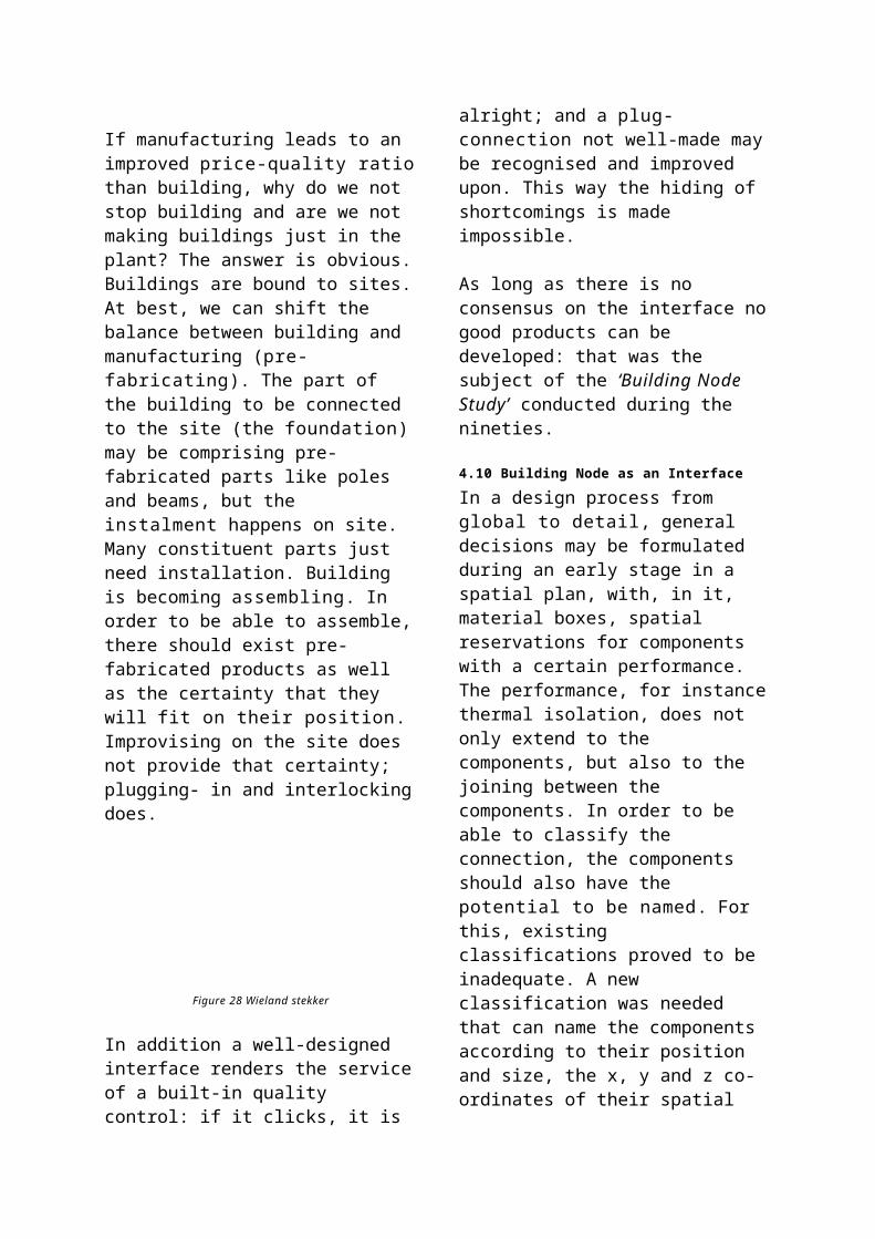
Figure 46 The stages of the innovation process
DevelopmentDuring the life-cycle of a product, a number of stages may be distinguished: pioneering stage, penetration stage, growing stage, saturation and the stage of exhaustion. Since no product features eternal life, enterprises face the pressing necessity of continuing to develop new products all the time.This process is called product development. A product development process starts with the product planning, in which an enterprise records its policy and strategies vis-à-vis an activity to be developed in a policy statement.Within this environment the enterprise starts studying what the market demands and what the strong and the weak points of the enterprise amount to. From these studies, ideas for a new activity may start to flow, of which the most promising one is recognised, selected and formulated.
This idea is worked out during ‘strict development’ into detailed designs for the product, production and exploitation.Next to this ‘technical development process’ the enterprise should reflect on a marketing plan (the four P’s according to Kotlera: Product, Price, Place and Promotion). This is called the ‘commercial development process’.Both processes (technical and commercial ) will not run very smoothly in practice; an idea has to grow. It purports that the processes should be structured in a concentric way: first all partial designs should be worked out globally in mutual inter-dependence in order to be able to pass judgement on its entirety. Following that, judgements of all partial designs are examined one more time and adapted where needed. The designs are growing helix-wise (in iteration) from vague ideas into concrete plans.
Figure 47 Iteration from vague to concrete
DesigningProduct designing is a form of problem solving. While designing, reasoning proceeds from objective (function) to means (design).This reasoning is not a formal logical process in which by the deductive form ‘If a Kotler, P. (1997) Marketing management: analysis, planning,
implementation and control.
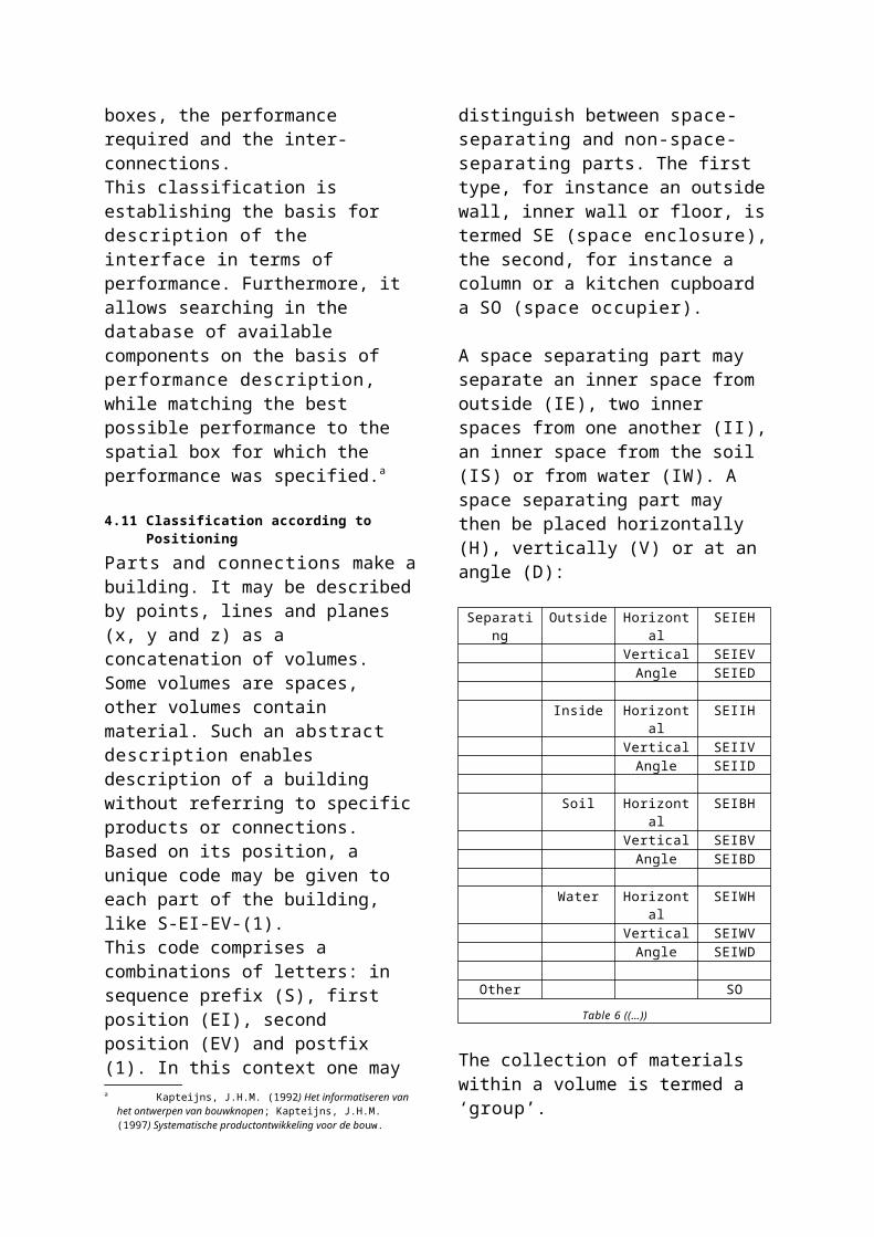
P then Q’ from data (premises P) the result Q logically follows. In designing the result Q precedes in a certain sense the premises P, although the final design is in all other aspects (shape, composition, materialisation) still uncertain. The pattern of reasoning, termed ‘innoduction’ by Roozenburg and Eekels, proceeds as follows:
1. Determining the functional behaviour envisaged (Q)
2. And making a design (P), whilst…3. … ensuring that the functional
behaviour is obeyed (P Q)
Further explanation is found in the Chapter on logic of the present book (see page Error: Reference source not found).During the design process, statements should be made on the shape of the design, the characteristics it should embody and the functions to be performed. The spatial form (geometrical) and physical-chemical form (material composition) a product should demonstrate after the manufacturing process is called the design of that product. The function of the product is the capability to realise a transformation in the material environment. This requires explanation.Our material environment is subject to change on a continuous basis. In principle with our design we want to steer one or more of all the processes taking place around us. The figure below a visualises some aspects.
Figure 48 The autonomous natural process
Above: without human activityBelow: with human activity
Without the coffee grinder the coffee beans would remain coffee beans. The grinder comprises characteristics making a transformation of the material environment possible. For we may also decide not to grind coffee beans; then the beans stay as they are. The function of a product exists therefore only in a relation to human activity.
6.3 Designing productsGenerally the structure of distinct design processes proves to be rather similar.a In the design process a number of stages may be discerned. These stages are described below as the base cycle of designing:
Figure 49 The base cycle of designing
Naturally, the design process does not run as smoothly as the staged model may suggest: it is an idealised model. Iterations with a particular stage have been left out. Nevertheless, staged models are indispensable for planning and controlling of product development process and
a Roozenburg and Eekels describe in their book various phase models: Pahl and Beitz (p. 114 figure 5.9), the Richtlijn VDI2221 (p. 119 figure 5.10) and the phasing according to Van den Kroonenberg en Siers (p. 120 figure 5.11) The structure is according to them in all three models almost identical, with differences just in details. Roozenburg, N.F.M. and J. Eekels (1998) Productontwerpen, structuur en methoden, 2nd ed.
determining mile-stones and points of decision.
Staged models are based on the idea the a design-in-emergence can exist in three principally different ways:
as function structure: a representation abstracting from concrete shape and material of the physical parts of the systema
as solution in principle: an idealised (schematic) rendering of the structure of a systemb, in which properties of elements and relations essential for technical functioning are determined in a qualitative way
as ‘materialised’ design; preliminary and / or final; in this, most characteristics of a product can be judged for the first time.
AnalysisFirst of all a problem statement must be defined: Who is owning the problem? What is the problem? What are the objectives?
Next the Programme of Requirements (PoR) must be made. A PoR may contain the following subject matter:
Verbal criteria (for instance: “the colour should be red”);
Ordinal criteria (for instance: “the sales-price should be as low as possible);
Norms; Specifications
A verbal criterion admits just two statements: the design is complying to the criterion; or not. A verbal criterion may be a demand as well as a wish.An ordinal criterion is always a wish. In the case of an ordinal criterion it is not possible to say bluntly that the design is satisfactory yes or no.Norms may be posed on a compulsory basis by an external agent and always have the status of a demand (for instance NEN norms).Specifications are statements on the geometry and/ or the material of the product. With this they fix the design a A system is a restricted conjunction of parts, termed the
elements of the system.b The structure of a system is a set of invariable relations
between the elements of the system (Roozenburg and Eekels). Following de Jong, structure is a set of separations and connections.
partially; by the same token care should be exercised with including specifications in the Programme of Requirements.In order to arrive at a complete and consistent set of criteria exploring the objective-mean-relations may be a tool.Certain relations may exist between objectives. Consequentially the set of criteria is often displaying an hierarchical structure; for instance in a chain of objectives and means. An example
Mean ObjectiveMoney VehicleVehicle TransportingTransporting WorkWork Money
A design is called ‘good’ if it is complying in a ‘good’ way to the PoR. Therefore, it is important that the PoR itself is already good and complete:
Each separate criterion should be valid; All criteria together should cover the
objective(s); The criteria should be maximally operational; The criteria must not be redundant; For transparency a Programme of
Requirements should be as succinct as possible;
The criteria should be accessible.
In case of an operational criterion it may be ascertained objectively to what extent the design is complying. However in practice it is often impossible to have a PoR with just operational criteria.
SynthesisThis is the generating of a preliminary design proposal. The result of this stage is called the ‘preliminary design’. During it, various creativity enhancing methods may be used:
Associative methods: brainstorming Creative methods: serendipity and
analogies: ‘Synectics’c
c Surprising ideas emerge from rather accidental confrontations of two situations: the problem situation and a situation seemingly not connected to it, or at a very significant distance. The ‘synectics’ procedure is trying to create an alienation through analogies vis-à-vis the problem.
Analytical-systematic methods: function analysis, the morphological methoda, Analysis of Inter-connected Decision Areas. b
SimulationSimulation is mimicking the behaviour of a system by means of another system. Simulation generates the factual information that is compared to the PoR during the processes of evaluation and decision. Simulation is a deductive sub-process: the designer wants to develop an idea of the behaviour and the characteristics by reasoning and/ or experimenting with models and of the inter-action with the product designed. This takes place before production in reality and actual use, so that possible mistakes may still be improved upon.
Evaluation and decision‘Evaluation’ is here understood to be determining the value or quality of the preliminary design. The characteristics expected are compared to the characteristics considered desirable as they have been formulated in the Programme of Requirements. Then the decision follows: either continuing and detailing the design proposal further (if the proposal is the final design it can be taken in production following approval); or going back to the stage of synthesis and making a better design proposal.
After the design stage a number of stages follow (not discussed here):
Production Distribution and sales Use Disposal
6.4 Designing architectureIn the previous paragraph the stages of the base cycle of designing have been described. In this paragraph staging a building process is discussed and the
a The morphological method tries to find all possible solution for a problem which are theoretically viable.
b AIDA (Analysis of Inter-connected Decision Areas) is a method for analysing problem situations where a number of mutually depending problems must be taken.
position therein of the design process. This base cycle is found back, by and large, in staging the building process as below.c
ProgrammeIn contrast to product design the owner of the problem in architecture is often known. His demands is then worded in a staged Programme of Requirements (PoR):d
a base programme a global PoR a detailed PoR
Usually a Programme of Requirements in architecture comprises the following items:
a general characteristic of the organisation to be housed and of the requirements put to the building location
an overview of the departments and their mutual relation
a survey per department of the spaces needed, including size and interior facilities for those spaces
a statement on the quality required and the finishing of the spaces
a statement on the technical installations needed
a statement on the technical and/ or economical life-cycle of the building that was determined.
Controlling the design processIn order to control the process the following cycle of control is used:
recording the current state of things comparison of this recorded state of things to
the norm possibly adaptation undertaking action in order to (continue to)
meet that norm (the time schedule)
The most important aspects of control are: time, money (costs) and information.
DesignDuring the designing stage possibilities for solution are being looked for on the basis of the PoR. The demands and wishes are being made concrete in the form of designs. The description of the final result is translated into a building mass, blue-prints, spaces
c Bondt, J.J. de, H.A. van Drunen et al. (1996) Bedrijfskunde. De fasering van het bouwproces, 2nd ed.
d See aldo Van der Voordt and Van Wegen on Programming of Buildings in the present book.
and use of materials. The Preliminary Design is a checking moment in the design process. Detailing and integration of the building and its installations are realised during the Final Design. Approval of authorities is asked on the basis of this design.A global assessment of costs can also be made on the basis of the preliminary design. CAD systems enable simulations.
Figure 50 Design process
ManualThe manual entails: description of the work; drawings belonging to them; applicable conditions; noting of informations.
Since building is featuring separate responsibilities for design and execution, the manual is a good tool of communication between the commissioner, designer and parties involved in the construction. The manual also provides guidance during execution of the activities of the work and a legal instrument in case of conflicting opinions.
Following the stage of the manual additional stages are discerneda, although they are beyond the horizon of the present Chapter:
contracting determination of costing construction planning execution maintenance and control
6.5 The product developer as a product enterprise
After having described some differences between a product and architecture as well as the design methodologies of both disciplines, it is now time to compare the rôle of a project developer and a product enterprise.The organisational environment of the two disciplines is rather different. If we restrict ourselves to the staging of the design process in both cases, it is obvious to compare an architectural office to a design studio in a product enterprise.
Since I think that a number of differences between product designing and architecture designing stem from the development path in a broader sense, I am comparing in this Chapter a ‘product enterprise’ to a ‘project
a The staging of the building process according to the Netherlands Normalisation Institute NNI: programme, initiative, feasibility study, project definition, design, structure design, preliminary design, final design, detailing, budget plan, pricing, realisation, work preparation, execution, transfer, maintenance, demolition.
developer’. According to me the two are passing through similar trajectories and processes. A product enterprise can hire for the technical design process an external design studio; just as a project developer can hire for the technical design process an architectural office.
Opd
rach
ten
van
part
icul
iere
n
Opd
rach
ten
van
bedr
ijven
Ont
wik
kele
n pr
oduc
ten
+be
denk
en id
eeën
(lat
en)
Ont
wer
pen
+ (l
aten
) ui
tvoe
ren
t.b.
v. M
assa
-pro
duct
ie
Mar
ketin
g vo
or
prod
uct
Architecten-bureau Ja Ja Nee Ja Nee Nee
Ontwerp-studio Nee Ja Nee Nee Ja Nee
Product-ondernemin
gNee Nee Ja Ja Ja Ja
Project-ontwikkelaar Nee Ja Ja Ja Ja Ja
Table 7 Players in architecture and product design
In this table a lot is rather black and white, and has been put down very incompletely.For completeness’ sake it should be mentioned that the product enterprise may of course also be an enterprise producing, for instance, mass-products for the construction market. In this vein a distinction may be made between a building product enterprise and a usage product enterprise.
6.6 Difference in policy and strategyProduct/ product enterpriseDefining a rather general direction the enterprise is striving to follow is predominant during this stage: what is the mission (objective of an enterprise in its direct and indirect field of competition for a period of ten to twenty years, the factual legitimising of the enterprise)? What is the vision (an imaginable view of the future of the enterprise, deemed feasible, in its market environment for a period of five to ten years)? What is the strategy (how to realise the vision) and what are the tactics (sequencing of actions with their corresponding resultsa)? Distinction may be made between an internal and an external
a Smulders, F.E.H.M., M.H. Kiers et al. (1998) Strategie en Organisatie: thema: productinnovatie.
component: the external implies that a number of trends in the environment of the enterprise should be charted. The internal component concerns charting the core competence(s).
Architecture/ project developerWe are taking it for granted that the enterprise has a certain objective. This objective can be translated into motifs of the enterprise:
economical technical and social
6.7 Looking for possibilitiesSince designing is regarded here as a form of problem solving, first of all there should be a ‘problem’. A problem is always associated with a supposed dis-satisfaction of people on aspects of a situation in which they find themselves. Next, a real problem presents itself, if the ‘problem owner’ is intending to change something in the situation (and if it is not in principle impossible to solve the problem).
Product / product enterpriseSince a product does not live eternally, enterprises face an enforcing necessity to develop new products continuously. This means that an enterprise must (continue to) study its market well. Within its policy formulationb, an enterprise is continuously trying to spot ‘problems’ in the market. One could say that enterprises have an active rôle in spotting and ‘solving’ problems (see page Error: Reference source not found).When looking for product ideas, it is first of all wise to delimit areas within which one is going to look: ‘search areas’. A search area is a realistic depiction of a future area of activity for an organisation, based on knowledge of external opportunities and awareness of internal capability and will. For finding fertile
b During product planning an enterprise records its policy and strategies concerning an activity to be developed in a policy formulation.
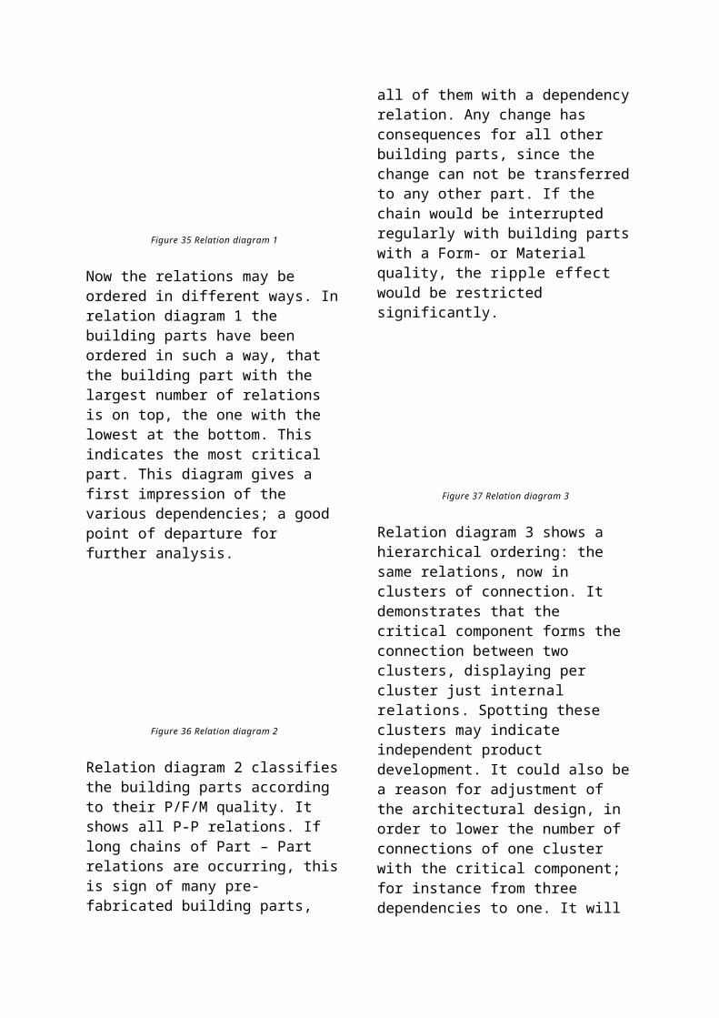
areas one needs criteria derived from the policy (in the preceding stage).This results in ideas for new activities; and among these ideas the best are selected.
Architecture/ project developerProject developers may play an active rôle in allocating ‘problems’ and looking for possibilities. Yet project developers are facing a less pressing necessity to realise solutions since an architecture product has a longer life-cycle than an industrial product. In addition an architecture product is preserving its value much longer: renting + exploiting + selling etc.
6.8 Idea analysisProduct / product enterpriseThere are a number of ideas. In this stage the specific possibilities should be studied further; deep insight into the needs of the potential purchasers should be acquired if possible. The result of this study is a product / market / technology combination (PMT-combination).Next, the need of the market may be mapped further. In that context important subjects and tools include:
insight in market need, getting a clear, detailed view of the target segment. This may be done by a qualitative consumer’s study(panel discussions) or a quantitative one (usually on paper, quantifiable). The study can be conducted among a-select respondents (potential users picked at random), problem owners (populations experiencing the need or problems in reality) or leading users;
opportunities for the enterprise: “Which product might cater for the problem spotted best?”
analysis of potential competition: who are they, how big are they and how many, what are the products they are marketing or going to get to the market, what are the niches they are aiming for, are these niches their core business, how does this fit in their development?
technology screening.
Architecture / project developerThree activities are central to this stagea: specifying the housing problems, looking
a Venemans, A. (1997) Bouwwijs; Huttinga, E., N. de Bont et al. (1999) Reader Bouwmanagement t.b.v. blok Productie & Uitvoering, 1st ed.
for solutions in principle and developing an action plan. This results in a ‘go / no go’ decision for the project. For the benefit of this decision the points of departure and the project result desired are recorded in a base programme. The plans for financing, boundary conditions and organisational form intended are also described in the action plan.
6.9 Idea definitionBy now, a lot of information has been collected and the whole of opportunities, potential market and possibilities for the enterprise has become clearer. Now it should be realistically described which activities should take place in order to transform the idea into a product, respectively into architecture.
Product / product enterpriseThe product to be developed must be integrated into the present organisation process. For this a detailed business-plan is written. It is important to distinguish four distinct processes and to plan and integrate them in parallel:
Product development: design, prototypes, etc.
Production development: development of the production process
Market development: making a marketing plan etc.
Organisation development: preparing for possible organisational changes.
6.10 Cross-fertilisationThe student of Industrial Design Engineering is actually educated to the equivalent of the project developer in the building process. I mean to say that a student Industrial Design Engineering has a more extended notion of the process as a whole: of organisation, via product innovation to the market. What exactly must happen if we want to view the architecture product as an industrial product?First of all, it is striking that a product enterprise puts out for itself very clearly a policy, together with strategies belonging to it. Generally, a product enterprise has a
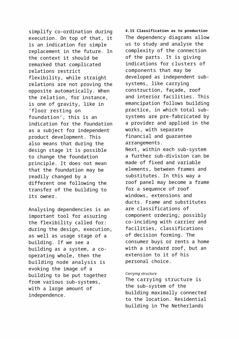
strong vision, also communicated to the world outside.
If we consider next the way both organisations look for possibilities, we see how a product enterprise is always busy with focusing on a more dynamic market: what kind of needs prevail, what are the opportunities to seize. In some cases this might apply to architectural design as well (for instance for a holiday park; ‘mass’ building, perhaps also for offices). We should spend more thought on the question which target group we envisage for architectural designing. Specific needs can be determined more readily for a specific target group. Cost reduction of ‘mass’ building results if an inventory of the needs has been made first. As mentioned earlier, usually architectural products can not hope to formulate all objectives. A part of the objectives might come into being by means of ‘design study’.
Idea analysis is more elaborate in product development and the need is more thoroughly ascertained. Also in the area of architecture designing, one is becoming active on stage: one is going to specify the housing problem and to make an action plan.
The idea definition in architecture is partly given by the PoR, partly elaborated in the manual by design. In product development it is elaborated in a design and a business plan. The advantage provided by a business plan is that it is also already mentioning ideas for marketing, organisational change and production. The design extends into the development fluently; while architecture designing is showing a clear border-line between the making of a PoR, the concrete design and the building process.
For architectural designs, studies of usage should be exploited more often than is done now. Some realised projects have failed, because the needs of the target group were not studied well, whether they were taken
into account or were being met. Studies of usage may enable adaptation of a number of items in an early stage.
Finally, it should be stated that in case of product development the product remains intellectual property of the enterprise. That enterprise will continue to earn money by it for a long time (patents, etc.). Perhaps a principle of that kind can also be thought out for architecture, by which a designer can continue to claim a right on his or her design for a longer period of time.
.
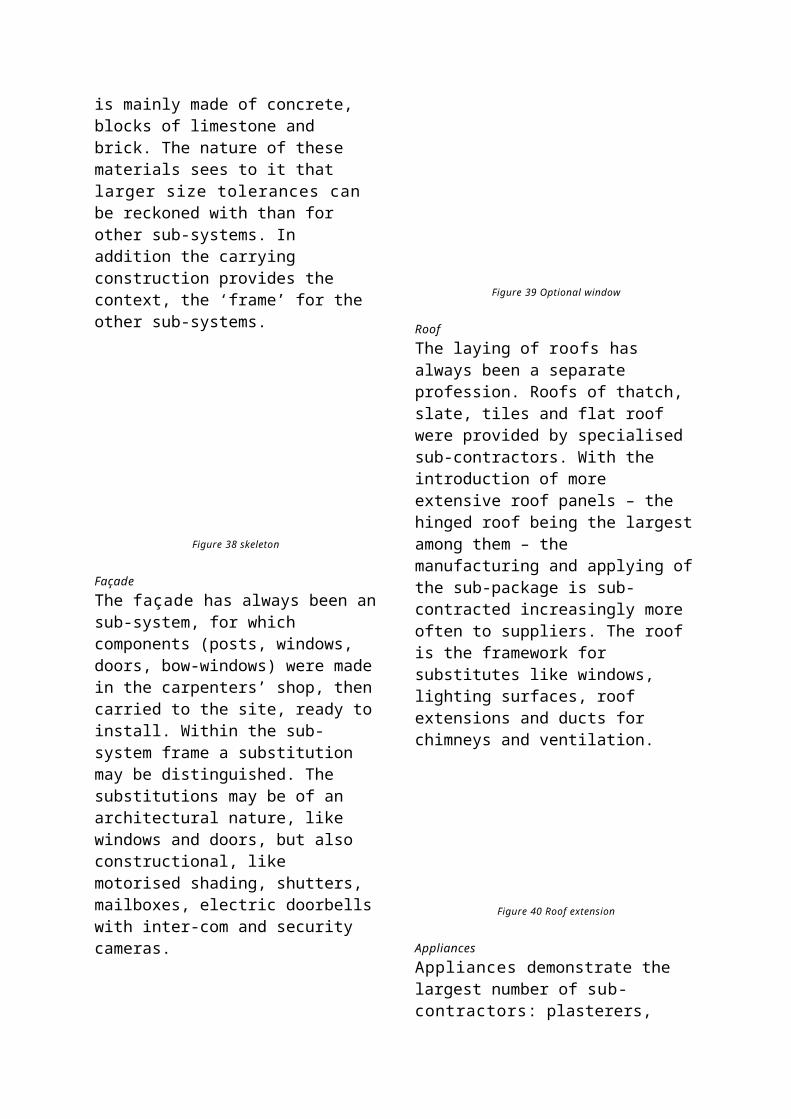
7 FUTURE ICT DEVELOPMENTS
Sevil Sariyildiz, Rudi Stouffs,Özer Çiftçioğlu, Bige Tunçer
40.1 Introduction.............................................32440.2 ICT in Building Design Process.............32440.3 Complexity in the Design Process........32540.4 The Rôle of ICT in the Creative Design
Process....................................................32540.5 Advanced Modelling Software and its
Impact on Practice..................................32640.6 Communication and Collaboration over
the Internet..............................................32740.7 ICT in Architectural Education...............32840.8 The Impact of Artificial intelligence on ICT
Enhanced Building Technology.............32840.9 Conclusions.............................................329
The building sector is entering a new era. Developments in information and communication technology (ICT) have an impact throughout the entire life-cycle of a building, not only from a process and technical point of view, but also from a creative one. As a result of developments of advanced modelling software for architectural design, the gap between what the architect can envision and what the building technician or product architect can materialise is enlarging. Internet technology has already started to provide a closer link between the participants in the building process, their activities, knowledge, and information. Concurrent and collaborative engineering will be the future of building practice with respect to efficiency and quality improvement of this sector. The nature of the building process is complex. Not only in terms of communication, but also of information of the number of participants, spatial organisation, infrastructure etc. In the near future, soft computing techniques like artificial neural networks, fuzzy logic, and genetic algorithms will make contributions to problem solving aspects of the complex design process. This Chapter provides an overview of these and other future developments of information and communication technology within the building sector.

7.1 IntroductionLooking back to historical developments in the building sector the development of technology has always had an impact how people designed, built and lived in a built environment. If cast iron was not invented there would not be a Eiffel Tower or if the car was not invented, we would still have the narrow streets of the middle ages. There are numerous examples that show the impact of the technological developments on the society itself, by changing habits and the way of living, and, therefore, the changes on the built environment.
As in other sciences, ICT also influences the building sector. We are entering a new era. This will cause innovations, improvements and new challenges in this sector.If we focus on the design process as a part of the building process, we can generally say that there are four main domains of applications of ICT in the design process.
1. Creative design orientated ICT (applied in the conceptual design or inception phase)
2. Materialisation orientated ICT (building physics and building technology aspects such as calculating bearing structures and detailing)
3. Realisation orientated ICT4. Process and management orientated ICT
(linking the first three categories or activities)
Within the on-going developments of ICT, the rôle and the daily work of the people involved in the design process are both changing. Until now this process was cut into a few periods. When the architect designed the concept, this goes to the constructor, to work out the materialisation step, and afterwards to the contractor to build. There is always the supervisor, the building manager steering this process. We are now entering into a new stage. This process is not sequential any more, but more a network type which we call information, communication and collaboration networking in the design process.
7.2 ICT in Building Design ProcessInitially computers were put into practice as a tool, as an instrument for achieving a specific result; a final drawing, an animation, a simulation, an interactive visualisation. Nowadays, computers have a different rôle as a new medium; next to the existing media within the architectural design process. Especially the widespread use of Internet and the developments of the Web have pushed the computer into the rôle of a medium.
In the near future, we can expect another shift in the rôle of computers in the design and building process, namely, as a partner.a ICT allows now to develop new techniques and methodologies using the computer as a partner by means of knowledge integration, decision support, and artificial intelligence. Decision support systems allow the computer to support the user through knowledge provided by experts or by the user herself. The computer can also be a partner when we teach it things it can reason with. It can even be a valuable and reliable friend when we let it solve problems not clearly defined, fuzzy, or uncertain. It can also assist in generating forms by processing information that influences the shape, supported by self-learning techniques. Here, artificial intelligence techniques like fuzzy logic, genetic algorithm and neural networks play an important rôle.
The ICT as Tool, Medium and Partner has the following support in the entire design process:
a McCullough, M. (1996) Abstracting craft: the practised digital hand; Sariyildiz, S., P. van der Veen et al. (1998) Computers as reliable and valuable partner; Schmitt, G. (1999) Information architecture: basics of CAAD and its future.
Tool3D modellingCAD (Computer Aided Drafting)Presentation (Animation, Simulation, Composition, Rendering etc.)Analysis
MediumInteractive visualisations (VR-Virtual Reality, Cyber Space)Information processing Communication (Internet Technology)Collaborative & Concurrent engineering, CSCWCAD-CAM, CAE, EEM (Enterprise Engineering Management) etc.
PartnerKnowledge Integration (ANN-Artificial neural Network, Fuzzy Logic, Intelligent Agents etc.Decision Support Systems-DSSAdvanced Modelling (Genetic Algorithms, Grammars etc.)Intelligent Management
Finally, the ICT means is meant to support the designer in the design process to achieve the intended goal. This goal can be differentiated for different users. The flexibility and the efficiency of these ICT means are an important item in the future.
7.3 Complexity in the Design ProcessBuildings are becoming more and more complex nowadays, not only in form and functions, but also in their infrastructure: their techniques and communications. Naturally, the design process is also becoming more complex. It is complex in the sense that many, often conflicting, interests and criteria are involved, and that many different types of expertise are required to find an optimal solution. Additionally, there is the uncertainty of the future use of the building, requiring the meeting of new criteria not defined explicitly at the moment of design. That means that a designer must have the ability to meet a certain range of criteria in a flexible way so that future demands are also met to a certain degree. The outcome of the design process has to fulfill different requirements of functional, formal, and technical nature. These requirements concern aspects like usability, economics, quality of form and space, social aspects of architectural design, technical norms or
laws, and technical and mechanical aspects of the design.
Building design is a multi-actor, multi-discipline, and multi-interest process. Design is teamwork among architects, designers, and consultants for various fields, e.g., building physics, construction, material science, electrical engineering, acoustics, geodetics, building economy, and environmental engineering. The process of decision-making is often intuitive and based on experience. Tedious discussions may occur in committees where all or many of the criteria are represented. The resulting decision is obviously a compromise, but it is often unclear how the decision was reached and whether better solutions exist. In this respect, the ICT tools and their integration form an essential component in the knowledge integration process of the various disciplines. As such, they are increasingly becoming a valuable and, hopefully, reliable partner in the design process.
To reach better communication and information exchange during the design process there were some initiatives to try out concurrent engineering in Europe. It was not successful for many reasons. Because the building sector in Europe is fragmented and still a bit old-fashioned in thinking concerning the innovations and technological developments. Concurrent engineering is now turning into collaborative engineering especially by the influence of Internet. The work can be continued any time, anywhere in the world. By means of VR the participants can communicate visually with each other. Therefore, is it worth-while to put effort into the developments of the broad-band technology also in Europe.
As mentioned earlier, in the building process we deal with complexity. There are many partners and knowledge disciplines involved. Information must be ordered and communication realised between various
disciplines and people involved. Management of Information, Communication and ICT means are, inevitably, tools in the future of the building sector. Collaborative engineering techniques can be a good start.
7.4 The Rôle of ICT in the Creative Design Process
The designer has to deal with three main categories of sciences, in the Netherlands called alpha, beta, and gamma sciences. Alpha sciences deal with the subjective world of beauty and ethics, as expressed by the artistic, intuitive soul. Beta sciences bring in the objective world of facts and logic, represented by the rational mind. Gamma sciences consider society and culture. Integration of these sciences makes the task of the designer more complex. The designer must have the skills to integrate the various disciplines of knowledge, involving besides the artistic form expression of the building also the dimensioning of the structure, building physics, applied mechanics, the calculation of structures, building materials and techniques, etc. The most famous designers, like Santiago Calatrava, are those who have the ability to combine these various disciplines in their designs as architect and building engineer.
When computers were first introduced in the building sector, the applications mainly concerned administrative tasks. Gradually their functionality extended to support repetitive tasks; nowadays, software applications are becoming essential tools for creative design, materialisation (building technical aspects), and the management of the entire building process. Already, for architects, like Peter Eisenman and Frank Gehry, employment of computational programs is an indispensable means, even if it holds no explanatory power over results.a
a Forster, K.W. (1996) Rising from the land, sinking into the ground.
In respect to creative design, spatial software development for design aids during the last years influences form finding and spatial design of the creative designer. Designing architects are more and more using the 3D modelling software like MAYA. During the International design workshop in the Netherlands Architecture Institute NAI we experienced that the design tool offered to the designer has considerable impact on how the designer is stimulated by the possibilities of the 3D modelling software. The designer dares to design more complex forms and has more flexibility. To see the rôle of the new software for design, an experimental workshop was organised by the NAI in Rotterdam. Designing architect Lars Spuybroek guided the students for the design context in collaboration with staff of Technical Design & Informatics at the Faculty of Architecture, TU-Delft. Within few days time the students could cope with various software MAYA to design a stadium.
Figure 51 Deformations
Figure 52 ‘Timeless’, Folded surface
7.5 Advanced Modelling Software and its Impact on Practice
As a result of developments in advanced modelling software and its use for architectural design, the gap between what the architect or designer can envision on one hand and what the building technician or product architect can materialise on the other is enlarging. The Guggenheim Museum (Figure 53) in Bilbao, Spain, designed by Frank Gehry, is a prime example. Designed using ‘Catia’, modelling software developed for the aerospace industry, the form of this design would have been much more difficult to establish using traditional tools and methods of designing. The architect is provided with a richer form vocabulary
and more flexibility to realise spatial ideas on the computer. Design software has reached a point where it can stimulate the designer's creativity rather than impede it as has been argued in opposition to CAD software. Also in Europe, many architects have adopted advanced modelling software for their creative design, like Dutch architects Kas Oosterhuis and Lars Spuybroek.a
Figure 53 Guggenheim, Inside and Outside
The developments in the field of building technology and building materials have not
a Schwartz, I. (1997) A testing ground for interactivity.
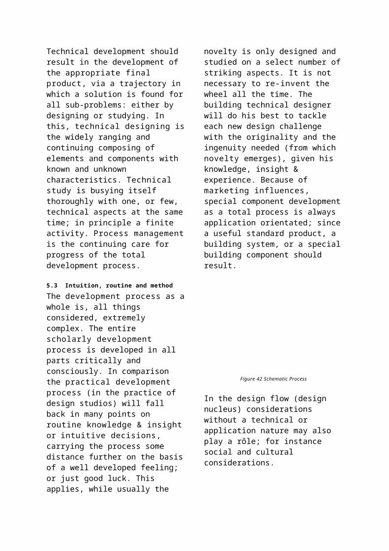
followed these advances in modelling software, so that they can no longer answer all the requirements and demands of the new architectural forms. ICT may play an important rôle in narrowing this gap. Electronic form information is transferred directly from the design model to computer-controlled manufacturing machines, as in the case of stone cutting for a curved wall. Unlike straight or even cylindrical surfaces, free-formed surfaces cannot be composed simply of standardised components; potentially each element may be of different size. This complicates the manufacturing process and causes cost explosion. Numerical or computer-controlled equipment enables custom components to be produced at a lower cost. Connecting it to the Internet, so that there is direct control from the design model further cuts cost. As custom manufacturing increasingly replaces standardised production, these costs will further decrease. Furthermore, as electronic catalogues are extended to include information on custom manufacturing techniques, possibly allowing designers to check manufacturability and price in the design phase, custom production will become more accessible.
7.6 Communication and Collaboration over the Internet
As the Web and Internet technologies are filtering into every aspect of society, they will have enormous impact on building practice. Already, architectural offices are using the Internet to communicate with partners across the globe, discussing designs. As distances become smaller, architects are empowered to take on a global rôle. Examples abound already, like the world's highest skyscraper in Kuala Lumpur, Malaysia, designed by Cesar Pelli Associates in the US. The use of Islamic geometric patterns in the design shows a strong influence of local culture.
Global access requires new ways of managing the design process. Building
projects are increasingly becoming teamwork, where no one person is solely responsible for a design. Well-defined control hierarchies and relationships are making place for more intricate collaborative processes not as readily planned and controlled. This requires an increasingly networked thinking that brings partners to closer inter-action but, without appropriate computational support, impedes the ease of overview and understanding.a Web-based document management systems serve as media for exchange of information between the collaborative partners and provide facilities for organising, viewing, and red-lining drawings and images.b These systems can also serve development and dissemination of tools supporting specific needs and processes, leading to integrated software environments as platform for various applications to communicate via the Internet.c
This evolution is founded on several universal Internet technologies, like TCP/IP, HTML, Java, and XML. Using them, it is pretty straightforward to create a Web application that runs on any platform. XML simplifies communication and improves agent technology. When exchanging XML-structured data, the only thing the partners need to agree on is the XML tag set used to represent the data. No other information about each other's systems is required. This makes it simple for new organisations to join an existing structure of data exchange. Similarly, XML-structured data makes it much easier for an agent to understand exactly what the data means and how it relates to other pieces of data it may already know, thereby easing one of the challenges when writing an agent, that is, to interpret the incoming information intelligently and respond to it accordingly. Another advantage to the use a Lottaz, C., R. Stouffs et al. (2000) Increasing
understanding during collaboration through advanced representations.
b Burchard, B. (2001) AEC project management online.c Lottaz, C., R. Stouffs et al. (2000) Increasing
understanding during collaboration through advanced representations.

of XML for structuring data is that it can easily be applied to existing data and information, for archiving or indexing such information. Unlike product model representations, XML structured data is easy for a human eye to read and understand, flexible in its application, and easily applied for specific purposes.a
Many disciplines are developing a framework for using the XML standard for electronic communications and data inter-change in their domain;b also the building industry (aecXML 1999). Considering the complexity of building projects and the un-structured and inter-related nature of the project data, the building community can benefit from a unifying strategy for data inter-change. This will not only make current data exchange and re-use practices more efficient, but will also result in savings through streamlining the worldwide transactions in the Architecture, Engineering, and Construction (AEC) community.
7.7 ICT in Architectural Education In the near future designers and professionals who educate the designers on the field of Computing in general, need to adapt themselves to rapid development. Up to now, in most CAD education at faculties of architecture, attention is paid to computers as a tool, partially as a medium for communication and information processing. Technological developments allow us now to look forward and go a step further.
It is necessary to introduce existing ICT means and techniques in education and the development of the mentioned subjects of ICT. In the future architects must be able to extend existing tools and integrate them into specific needs. The level of education must be pushed: to the level that the computer is not only a tool or medium, but also a partner in Knowledge Integration, a Tunçer, B. and R. Stouffs (2000) Modeling building
project information.b Cover, R. (2000) The XML cover Pages (Extensible
Markup Language).
advanced modelling techniques, and a support environment during the design process.
If these developments will be left to the others than architects, the architects will face the danger that they become slaves of the tools, not the boss; partially the same kind of problem is present with the commercial tools. No commercial CAD product supports the designer as it should. The user must learn the basic principles to use the software and take the advantage of it in an efficient way. This basic knowledge should be given to the architecture students in their first year.On the other hand, the student of the future will be a mobile student working at any time from any place. Therefore, distance learning possibilities will gain an important rôle in the future for the academics, involved in the education.
7.8 The Impact of Artificial intelligence on ICT Enhanced Building Technology
Design requires more comprehensive attention than ever. There is no doubt that the available building information must be used effectively. ICT can play a rôle in eliciting this information in a timely and exhaustive manner. Several emerging technologies have important relevance to the use of ICT in the building process and, ensuing, important implications.
As information and knowledge are being stored at a continuously growing pace, buried in gigabytes of records, they are becoming less comprehensible. Faced with difficulties of retrieving them and making them available in an easily comprehensible format at higher levels of summarisation, this information becomes less and less useful. No human can use such data effectively and be able to understand the essential trends in order to make rational decisions. With reference to this phenomenon of information over-load, emerging technologies such as knowledge discovery and data mining offer a prospect of help. Knowledge discovery is inherently
connected to databases: in inter-action with a database, a search for patterns or objects is performed, eliciting meaningful pieces of knowledge. Data mining provides means or methods to attain this knowledge. Among the most promising methods for data mining are artificial neural networks, fuzzy logic, and heuristic search methods like genetic algorithms. Collectively, these are referred to as ‘soft’ computing methods; heuristic search methods as ‘evolutionary algorithms’. Artificial neural networks call for processing numeric data and building non-linear relationships. Fuzzy sets concentrate on representation of data at a nonnumeric level. The symbiotic co-operation of the two technologies results in an effect on the granularity of information.
These soft computing methods are receiving growing importance in almost every field, including building technology; slower there. Presumably, the basic reason for this is the difficulty of formulating building technological problems in a way that they become convenient for artificial neural treatment. However, these methods are especially important in the building sector, as they can handle information in various forms. A unified representation for artificial neural networks and fuzzy logic is already established.a It is likely that the communication between building technology and soft computing technology will be much easier than before;, due to the possibility of processing information at hand more human-like in coming years than previously.
Currently, this information processing, in combination with knowledge base systems, is mostly introduced by way of expert systems or decision support systems; in most cases unsatisfactory. In the future, we may expect computational intelligence systems to play a more important rôle.
a Jang, J-S., C-T. Sun et al. (1997) Neuro-fuzzy and soft computing: a computational approach to learning and machine intelligence.
Intelligent systems are increasingly replacing conventional systems: see intelligent manufacturing and intelligent design technologies. Some basic Artificial Intelligence (AI) fields associated with the emerging technologies connected to ICT development are indicated in Figure 54. In order to cope with the demands of information acquisition and information handling of these intelligent technologies, new methodologies and techniques are being developed. Besides knowledge discovery and data mining technology, agent technology is an example.
An agent is a software program designed for a specific purpose or functionality, acting autonomously to some extent; may be intelligently too.b Agent technology is closely associated with ICT: agents are generally conceived for communication with other agents or software and for transmission to distant computers. The Internet allows a distant computer to be any machine on the globe. Agents are especially promising for mining databases. As an example, a fuzzy engineering agent can interact with a building design database in order to identify various trends of engineering or architectural nature. In connection with virtual reality (VR), agents can assist in design by providing sufficiently realistic feedback early in the design process. This should ease early integration of design components, particularly in collaborative design.c Especially for collaborative design, agents have an important rôle to play to assist participants in their task or communication, or to offer additional functionality in project-management applications.d
b Jennings, N.R. and Woolridge M.J. (1998) Agent technology: foundations, applications, and markets.
c Abarbanel, R., E. Brechner et al. (1997) FlyThru the Boeing 777, formal aspects of collaborative CAD.
d Stouffs, R., D. Kurmann et al. (1998) An information architecture for the virtual AEC company.
Figure 54 Basic AI fields
Some basic AI fields of importance to ICT developments with impact on building technology.
7.9 ConclusionsOngoing development in ICT has an important impact on the design and building process. Designers can allow ideas and intuitions to take physical shape in ways not possible before.a At the same time, building technical developments are lagging behind. Alternative, innovative solutions have to be adopted. At the University of Cincinnati, "all building trades (plumbing, tiling, painting) were carried out through a three-dimensional co-ordinate numerical control system implemented by an electronic laser transit on the site".b Future ICT developments for architecture and the building sector will be in the field of knowledge integration and decision support environments leading, finally, to ICT support in the entire building process, from initiative until demolition. Collaborative engineering will pervade the building design process. By these technologies, the branches of scientific disciplines will come closer than ever before to an integration. In the future, each participant in the design process will need to be able to make her own computer model in order to build up specific knowledge within it and use it as a partner in the design. Developments in the software industry show that if software firms provide the software core, architects a Forster, K.W. (1996) Rising from the land, sinking into
the ground.b Zaera-Polo, A. (1996) The making of the machine:
powerless control as a critical strategy.
and building engineers will be able to develop their own application tools according to specific requirements and needs. Independent of existing tools, they will be even free to create their own language of activities. Ongoing developments of Internet technology require other ways of design management and communication (data and partners communication) in the building process.