Embed Size (px)
Citation preview

7/31/2019 A 180 Class Doc
http://slidepdf.com/reader/full/a-180-class-doc 1/122
Us e r’s Man u al
HP 9000 Mod e l A-180
Manufacturing Part Number:
Aclassdoc00
February 2000
7/31/2019 A 180 Class Doc
http://slidepdf.com/reader/full/a-180-class-doc 2/122
2
Legal Notices
The inform at ion in th is docum ent is subject t o cha nge without notice.
Hewlet t-Packard m akes n o warranty of any k in d wit h regard to th is m anual, in clu d in g, bu t not lim ited to, the im plied w arran ties of m erchan tability and fitness for a particular
purp ose. Hewlett-Packar d sh all not be held liable for errors cont ained h erein or direct,
indirect, special, incident al or consequen tial da ma ges in conn ection with th e furnish ing,
perform an ce, or u se of th is ma terial.
Restricted Rights Legen d. Use, dup licat ion or disclosu re by th e U.S. Govern men t is
su bject t o rest rictions as s et fort h in s ubpa ra gra ph (c) (1) (ii) of th e Right s in Techn ical
Dat a a nd Compu ter Softwar e clau se at DFARS 252.227-7013 for DOD agencies, and
su bpar agr aph s (c) (1) an d (c) (2) of th e Comm ercial Comp ut er Softwa re Rest ricted Right s
clau se a t FAR 52.227-19 for oth er a gencies.
HE WLETT-PACKARD COMPANY 3000 H an over Str eet Palo Alto, Californ ia 94304 U.S.A.
Copyright Notices . ©copyright 1983-2000 Hewlett-Packard Company, all rights
reserved. Reproduction , adaptation, or translation of this docum ent w ithout
prior written pe rmiss ion is prohibited, exce pt as al lowe d unde r the copyright
laws .
Tradem ark Notices . UNIX is a registered tra demark in t he United Stat es and other
countries, licensed exclusively through X/Open Company Limited.

7/31/2019 A 180 Class Doc
http://slidepdf.com/reader/full/a-180-class-doc 3/122
Chapter 1 3
A-Class System Overview and Reference
1 A-Class System Overview andReference
aclassdoc00

7/31/2019 A 180 Class Doc
http://slidepdf.com/reader/full/a-180-class-doc 4/122
4 Chapter 1
A-Class System Overview and Reference
A-Class Server - System Overview
A-Class Server - System Overview
The A-Class server is a compact addition to the HP9000 server family, targeted atthe ISP server market. The A-Class server design allows the use of existing qualifiedperipherals and I/O add-in options. It is a PCXL-2 (PA-7300 RISC Processor) basedplatform designed to support the UNIX Internet Service Provider (ISP) market.
System Hardware Overview
A-Class server hardware has the following characteristics:
• It has a two rack unit height that makes it suitable for racked (up to 20 per rack)or stand-alone installations.
• It comes configured with one (1-way) 180 MHz. PA-7300 RISC Processor. An
additional (optional) 1Mb of 2nd-level cache is available.• It has eight RAM memory slots that can use 128, 256 or 512MB memory
modules.
• There are two I/O slots each capable of handling either PCI or HSC add-in cards.One slot is Access Port (AP) card capable.
• The embedded disk bay is capable of supporting 2 single-ended type-1 SCSIdrives.
• The server supports the following core I/O functions:
One 10/100 Base-T port supports connection to the primary LAN.
One 10 Base-T Port supports connection to the integrated web-based
console.
One 9-Pin RS-232 port supports connection to an ASCII console.
The internal SCSI bus is available externally to connect additional

7/31/2019 A 180 Class Doc
http://slidepdf.com/reader/full/a-180-class-doc 5/122
Chapter 1 5
A-Class System Overview and Reference
A-Class Server - System Overview
single-ended Type-1 SCSI devices.
System Software Overview
A-Class servers require the HP-UX 10.20 or 11.0 operating system with anIndependent Peripheral Release (IPR) date of October 1998 (9810) or later.
NOTE HP-UX is the only supported operating system for A-Class servers.

7/31/2019 A 180 Class Doc
http://slidepdf.com/reader/full/a-180-class-doc 6/122
6 Chapter 1
A-Class System Overview and Reference
A-Class Server Service Reference Information
A-Class Server Service Reference Information
Overview
Service reference data consists of the following:
• “A-Class Server System Block Diagram” for maintenance personnel andoperators.
• “A-Class Server System Regulatory Compliance Statements” required by the U.S. government and required by some countries that import HP products.

7/31/2019 A 180 Class Doc
http://slidepdf.com/reader/full/a-180-class-doc 7/122
Chapter 1 7
A-Class System Overview and Reference
A-Class Server System Block Diagram
A-Class Server System Block Diagram
Overview
The A-Class server block diagram is included for information.

7/31/2019 A 180 Class Doc
http://slidepdf.com/reader/full/a-180-class-doc 8/122
8 Chapter 1
A-Class System Overview and Reference
A-Class Server System Regulatory Compliance Statements
A-Class Server System Regulatory Compliance
Statements
Overview
Regulatory Compliance statements are required by some countries for internationalimportation of A-Class servers. The following information is provided:
“Regulatory Information”
“Safety”
“Declaration of Conformity”
“FCC STATEMENT (USA Only)”
“FCC Regulations for Telephone Line Interconnection”
“Canada RFI Statement”
“European Union RFI Statement”
“Japan RFI Statement”
“Korean RFI Statement”
“Taiwan RFI Statement”
“Japan-Only JATE Mark”
“Japan Harmonic Statement”
“Acoustics (Germany)”
“UK General Approval (United Kingdom only)”
“Internal Modem and HP A2991-600xx Line Access Module (LAM)”
“Terminal DOC (Canada only)”

7/31/2019 A 180 Class Doc
http://slidepdf.com/reader/full/a-180-class-doc 9/122
Chapter 1 9
A-Class System Overview and Reference
A-Class Server System Regulatory Compliance Statements
“National Post and Telecom Agency Statement (Sweden only)”
“AUSTEL Telecom Statement (Australia only)”
“New Zealand and Telecom Statement (New Zealand only)”

7/31/2019 A 180 Class Doc
http://slidepdf.com/reader/full/a-180-class-doc 10/122
10 Chapter 1
A-Class System Overview and Reference
A-Class Server System Regulatory Compliance Statements
Regulatory Information
For your protection, this product has been tested for conformance to various nationaland international regulations and standards. The scope of this regulatory testingincludes electrical and mechanical safety, electromagnetic emissions, immunity,acoustics and hazardous materials.
When required, approvals are obtained from third party test agencies. Approvalmarks appear on the product label. In addition, various regulatory bodies requiresome information under the headings listed in this section.
Safety
This product has not been evaluated for connection to an “IT” power system (acdistribution system having no direct connection to earth according to IEC 950).
Locate the AC outlet near the computer! The ac power cord is this product's main acdisconnect device and must be easily accessible at all times.
Battery Notice
This product contains a Lithium battery.
This battery is not to be removed or replaced by the user. If the battery needs to bereplaced, contact your Hewlett-Packard authorized service personnel.
CAUTION Lithium batteries may explode if mistreated. Do not recharge, disassemble, ordispose of in a fire.
Please properly recycle all used batteries.

7/31/2019 A 180 Class Doc
http://slidepdf.com/reader/full/a-180-class-doc 11/122
Chapter 1 11
A-Class System Overview and Reference
A-Class Server System Regulatory Compliance Statements
Declaration of Conformity
FCC STATEMENT (USA Only)
The United States Federal Communications Commission has specified that thefollowing notice be brought to the attention of users of this product:
NOTE This equipment has been tested and found to comply with the limits for a Class Adigital device, pursuant to part 15 of the FCC rules. These limits are designed toprovide reasonable protection against harmful interference when the equipment isoperated in a commercial environment. This equipment generates, uses, and can
radiate radio frequency energy and, if not installed and used in accordance with theinstruction manual, may cause harmful interference to radio communications.Operation of this equipment in a residential area is likely to cause harmfulinterference in which case the user will be required to correct the interference at hisown expense.
Hewlett-Packard's system verification tests were conducted with HP-supportedperipheral devices and HP shielded cables, such as those you receive with yourcomputer. Changes or modifications not expressly approved by Hewlett-Packardcould void the user's authority to operate the equipment. Cables used with thisdevice must be properly shielded to comply with the requirements of the FCC.
FCC Regulations for Telephone Line Interconnection
• This equipment complies with Part 68 of the FCC rules. On the outside surfaceof this equipment is a label that contains, among other information, the FCCregistration, the FCC registration number and ringer equivalence number(REN). If requested, this information must be provided to the telephonecompany.
• This equipment uses the following Universal Service Code (USOC) jacks:RJ11C or RJ11W (single line).
• The REN is used to determine the quality of devices which may be connected tothe telephone line. Excessive RENs on the telephone line may result in thedevices not ringing in response to an incoming call. In most, but not all areas,
the sum of the RENs should not exceed five (5.0). To be certain of the number of devices that may be connected to the line, as determined by total RENs, contactthe telephone company to determine the maximum REN for the calling area.
• If this equipment causes harm to the telephone network, the telephone company

7/31/2019 A 180 Class Doc
http://slidepdf.com/reader/full/a-180-class-doc 12/122
12 Chapter 1
A-Class System Overview and Reference
A-Class Server System Regulatory Compliance Statements
will, where practicable, notify you in advance that temporary discontinuance of service may be required. If advance notice isn’t practical, the telephonecompany will notify the customer as soon as possible. Also, you will be advisedof your right to file a complaint with the FCC if you believe it is necessary.
• The telephone company may make changes in its facilities, equipment,operations, or procedures that could affect the operation of the equipment. If thishappens, the telephone company will provide advance notice in order for you tomake the necessary modifications in order to maintain uninterrupted service.
• If trouble is experienced with this equipment, please contact: Hewlett-PackardCompany, Response Center, 20 Perimeter Summit Boulevard, Atlanta, GA30319 U.S.A. 1 (800) 633-3600 (Toll Free - North America Only) or 1 (404)
648-0000 (Main Number)for repair and/or warranty information. If the trouble is causing harm to thetelephone network, the telephone company may request that you remove theequipment from the network until the problem is resolved.
• No repairs are to be made by you. Repairs are to be made only byHewlett-Packard or its licensees. Unauthorized repairs void registration andwarranty.
• This equipment cannot be used on telephone company-provided coin service.Connection to Party Line Service is subject to state tariffs. (Contact the statepublic utility commission, public service commission, or corporationcommission for information).
• If so required, this equipment is hearing-aid compatible.
Canada RFI Statement
• This Class A digital apparatus meets all requirements of the CanadianInterference-Causing Equipment Regulations.
• Cet appareil numÅrique de la classe A respecte toutes les exigences duRÉglement sur le matÅriel brouilleur du Canada.
European Union RFI Statement
This is a Class A product. In a domestic environment, this product may cause radiointerference in which case the user may be required to take adequate measures.

7/31/2019 A 180 Class Doc
http://slidepdf.com/reader/full/a-180-class-doc 13/122
Chapter 1 13
A-Class System Overview and Reference
A-Class Server System Regulatory Compliance Statements
Japan RFI Statement
Korean RFI Statement
Taiwan RFI Statement
Japan-Only JATE Mark

7/31/2019 A 180 Class Doc
http://slidepdf.com/reader/full/a-180-class-doc 14/122
14 Chapter 1
A-Class System Overview and Reference
A-Class Server System Regulatory Compliance Statements
Japan Harmonic Statement
Acoustics (Germany)
Acoustic noise level per ISO 9296 (25 C):
LpAm <57dB (operators position)
GerÌuschemission nach ISO 9296 (25 C):
LpAm <57dB (Arbeitsplatte)
UK General Approval (United Kingdom only)
Pursuant to Section 22 of Telecommunications Act of 1984, this product is approvedfor indirect connection to Public Telecommunications systems within the UnitedKingdom under the General Approval number NS/G/1234/J/100003.
Internal Modem and HP A2991-600xx Line Access Module (LAM)
The following warnings apply to the use of the HP 2991-60001 internal modem andHP A2991-600xx LAM that may be provided with the computer.
Terminal DOC (Canada only)
NOTE The Canadian Department of Communications label identifies certified equipment.This certification means that the equipment meets certain telecommunicationnetwork protective operational and safety requirements. The Department does not
guarantee the equipment will operate to the user's satisfaction.
Before installing this equipment, users should ensure that it is permissible to be

7/31/2019 A 180 Class Doc
http://slidepdf.com/reader/full/a-180-class-doc 15/122
Chapter 1 15
A-Class System Overview and Reference
A-Class Server System Regulatory Compliance Statements
connected to the facilities of the local telecommunications company. The equipmentmust also be installed using an acceptable method of connection. In some cases, thecompany's inside wiring associated with a single line individual service may beextended by means of a certified assembly (telephone extension cord). The customershould be aware that compliance with the above conditions may not preventdegradation of service in some situations.
Repairs to certified equipment should be made by an authorized Canadianmaintenance facility designated by the supplier. Any repairs or alterations made bythe user to this equipment, or equipment malfunctions, may give thetelecommunications company cause to request the user to disconnect the equipment.
Users should ensure for their own protection that the electrical ground connections
of the power utility, telephone lines and internal metallic water pipe system, if present, are connected together. This precaution may be particularly important inrural areas.
The Load Number (LN) assigned to each terminal device denotes the percentage of total load to be connected to a telephone loop which is used by the device to preventoverloading. The termination on a loop may consist of any combination of devicessubject only to the requirement that the total of the Load Numbers of all devicesdoes not exceed 100. The load number for this product is 33.
CAUTION Users should not attempt to make such connections themselves, but should contactthe appropriate electric inspection authority, or electrician, as appropriate.
National Post and Telecom Agency Statement (Sweden only)
The LAM Interface shall be connected to SELV (max.42.4 V peak, or 60 V DC)according to EN 60950. (The internal modem complies with this requirement.)
AUSTEL Telecom Statement (Australia only)
When setting the number of automatic redials for the modem, ensure the following:
The number of automatic redials that the modem performs should be limited to amaximum of 9 redials plus the original call. If the above retries are unsuccessful, nofurther attempts should be made to the same number for a minimum period of 5
minutes.
CAUTION Failure to set the modem, and any communication software used with the modem tothe values contained in the listing will result in the modem being operated in a

7/31/2019 A 180 Class Doc
http://slidepdf.com/reader/full/a-180-class-doc 16/122
16 Chapter 1
A-Class System Overview and Reference
A-Class Server System Regulatory Compliance Statements
non-compliant manner. Consequently, there would be no permit in force for thisequipment, and the Telecommunications Act 1991 prescribes a penalty of A$12,000for the connection of non-permitted equipment.
Australian C-Tick Label
New Zealand and Telecom Statement (New Zealand only)
When using an application software that allows the setting of automatic redialing,the following guidelines should be followed:
• Not more than five call attempts to the same number within a one hour period.
• A minimum of 60 seconds between each attempt.
• Not more than a total of 10 call attempts to the same number.
Any setting that violates the above guidelines will cause the equipment to go out of compliance, and thus no Telepermit will be in force for this equipment which willmake it subject to penalties.
The operation of this equipment on the same line as telephones or other equipmentwith audible warning devices or automatic ring detectors will give rise to bell tinkleor noise and may cause false tripping of the ring detector. Should such problemsoccur, the user is not to contact Telecom Faults Service.
7/31/2019 A 180 Class Doc
http://slidepdf.com/reader/full/a-180-class-doc 17/122
Chapter 2 17
A-Class Server Installation
2 A-Class Server Installation
aclassdoc00

7/31/2019 A 180 Class Doc
http://slidepdf.com/reader/full/a-180-class-doc 18/122
18 Chapter 2
A-Class Server Installation
A-Class Server System Installation
A-Class Server System Installation
Overview
The sections listed below describe the procedures you will use to prepare for, install,and begin operation of, your A-Class server:
“A-Class Server Site Preparation”. Contains environmental requirements forpreparing the area where your server is to be located.
“Stand-Alone A-Class Server Unpack and Install Instructions”. Details what youwill find when you open the carton containing your A-Class server and how toset it up for stand-alone operation.
“Cabinet-Mounted A-Class Server System Unpack and Install”. Tells you how
to install and connect the server to external devices and power, either as astand-alone unit or in an HP-supported cabinet. Unpacking, set up, andconnection information is also included for those who ordered a cabinet from thefactory with one or more servers installed,
“A-Class Server System Software Configuration”. Tells you how to installmemory (RAM), cache memory, embedded disk and I/O card add-oncomponents.
“A-Class Server Power Up and Boot Procedures”. Leads you through theprocess for powering up external devices and the server, gives the softwarecommands for customizing the A-Class Secure Web Console IP address, andlists the steps required for booting the server to an operating state.
“A-Class Server System Software Configuration”. Directs you to the softwarecommands necessary for preparing both the A-Class server and the A-ClassSecure Web Server for operation.

7/31/2019 A 180 Class Doc
http://slidepdf.com/reader/full/a-180-class-doc 19/122
Chapter 2 19
A-Class Server Installation
A-Class Server Site Preparation
A-Class Server Site Preparation
Overview
This section contains the following environmental requirements for preparing a sitefor the A-Class Server:
“Space Requirements”. Space requirements for both stand-alone andcabinet-mounted A-Class servers.
“Input Power Requirements”. Nominal input voltage, nominal frequency, andtypical current requirements.
“Cooling Requirements”. Operating and non-operating temperature extremesand relative humidity parameters.
Space Requirements
Stand-Alone Server Dimensions
The physical characteristics of the A-Class server are listed as follows:
Dimension
Height 8.89 cm (3.5 in.)
Width 43.18 cm (17 in.)
Depth 58.42 cm (23 in.)
Weight 9.98kg (22 lbs)

7/31/2019 A 180 Class Doc
http://slidepdf.com/reader/full/a-180-class-doc 20/122
20 Chapter 2
A-Class Server Installation
A-Class Server Site Preparation
Stand-Alone Server Minimum Service Access Requirements
CAUTION Stacking A-Class servers in any manner and mounting in any cabinet other than aHewlett-Packard approved cabinet, is not supported.
While they are constructed to be strong, A-Class servers have not been tested forstacking load carrying capacity. Failure to follow this precaution may result in majordamage to the server.
Access Location
Rear 15 cm (6 in.)
Sides 7.5 cm (3 in.)
Front 7.5 cm (3 in.)
23” (58.42cm)

7/31/2019 A 180 Class Doc
http://slidepdf.com/reader/full/a-180-class-doc 21/122
Chapter 2 21
A-Class Server Installation
A-Class Server Site Preparation
Cabinet Dimensions
A-Class servers can be installed in any of the following cabinets:
Cabinet Product
Number
Description EIA Max.
A-Class
Servers
External Dimensions (width x depth x
height)
Centimeters Inches
A4900A Factory Integrated1.25m x 19” Cabinet
25 12 59.7 x 100.3 x 125.7 23.5 x 39.5 x 49.5
A4901A Factory Integrated1.6m x 19” Cabinet
33 16 59.7 x 100.3 x 161.3 23.5 x 39.5 x 63.5
A4902A Factory Integrated2.0m x 19” Cabinet
41 20 59.7 x 100.3 x 196.9 23.5 x 39.5 x 77.5
J1502A Field Integrated1.25m x 19” Cabinet
25 12 59.7 x 100.3 x 125.7 23.5 x 39.5 x 49.5
J1501A Field Integrated 1.6mx 19” Cabinet
33 16 59.7 x 100.3 x 161.3 23.5 x 39.5 x 63.5
J1500A Field Integrated 2.0mx 19” Cabinet
41 20 59.7 x 100.3 x 196.9 23.5 x 39.5 x 77.5
C2785A Field Integrated 1.1mx 19” Cabinet
21 10 61 x 91.4 x 111.8 24 x 36 x 44
C2786A Field Integrated 1.6mx 19” Cabinet
32 16 61 x 91.4 x 162.6 24 x 36 x 64
C2787A Field Integrated 2.0mx 19” Cabinet
41 20 61 x 91.4 x 203.2 24 x 36 x 80

7/31/2019 A 180 Class Doc
http://slidepdf.com/reader/full/a-180-class-doc 22/122
22 Chapter 2
A-Class Server Installation
A-Class Server Site Preparation
Cabinet Minimum Service Access Requirements
Input Power Requirements
Input power requirements for the A-Class server are listed as follows:• Nominal Input Voltage (VAC): 100 - 240
• Nominal Frequency: 50 or 60 Hz
• Typical current requirements:
1.0A at 100V
0.43A at 240V.
If an Uninterruptible Power Supply (UPS) is to be used, ensure that it is properlyconnected to the server. Refer to the, “External Connections” section for UPSinformation.
Power cord plugs for stand-alone servers are configured to meet unique powerconfigurations used all over the world.
Cabinet-mounted servers have the same power requirements as stand-alone servers.However, the power cords for cabinets are dependent on the type of PowerDistribution Unit (PDU) operation.
PDU power cords with one end stripped are also available for attachingcountry-specific power plugs. Refer to the cabinet documentation for more electricalpower information.
Cooling Requirements
Temperature ParametersThe operating and non-operating temperatures shown below are the extremes at
Access Location
Rear 61 cm (24 in.)
Sides NA (NA)
Front 100.3 (39.5 in.)

7/31/2019 A 180 Class Doc
http://slidepdf.com/reader/full/a-180-class-doc 23/122
Chapter 2 23
A-Class Server Installation
A-Class Server Site Preparation
which server parameters have been established.
Relative Humidity
Operating and non-operating relative humidity parameters are shown below:
Operating Non-Operating
+5°-+35°C
(41° - 95°F)
-40° - +65°C
(-40° - 149°F)
Operating Relative Humidity Non-Operating Relative Humidity
15% to 80%, non-condensing 5% to 90%, non-condensing

7/31/2019 A 180 Class Doc
http://slidepdf.com/reader/full/a-180-class-doc 24/122
24 Chapter 2
A-Class Server Installation
Stand-Alone A-Class Server Unpack and Install Instructions
Stand-Alone A-Class Server Unpack and Install
Instructions
Overview
Unpacking the A-Class server consists of opening and unloading the carton. Insidethe carton you will find, in addition to the server, an accessory kit and a packetcontaining installation instructions and regulatory information.
“Open and Unload the Carton”
“Unpack the Server”
“Open the Accessory Kit”
“Open the Installation Instructions and Regulatory Information Packet”
NOTE The following instructions do not apply to A-Class servers that are receivedpre-installed in a cabinet. These procedures pertain to individual servers, only.
Open and Unload the Carton
Step 1. Place the sealed carton on a work surface with the correct side up as indicated by the“This Side Up” symbol (below).
CAUTION Use sharp instruments carefully when unpacking electronics equipment. Failure to

7/31/2019 A 180 Class Doc
http://slidepdf.com/reader/full/a-180-class-doc 25/122
Chapter 2 25
A-Class Server Installation
Stand-Alone A-Class Server Unpack and Install Instructions
follow this precaution may result in personal injury or damage to components.
Step 2. Carefully open the carton, remove the contents, and set them on the work surface.Each carton will contain:
o The server.
o An accessory kit.
o A packet containing installation instructions and regulatory information.
NOTE Report any missing items to your local Hewlett-Packard office immediately. If thereis obvious freight damage, contact your shipper immediately.
We recommend that you retain all packing materials in case any of the itemsreceived require return to Hewlett-Packard.
Unpack the Server
CAUTION Do not set the server on its side, or in any position other than upright on its rubber“feet,” for operation. Failure to observe this precaution may result in component
damage or loss of system reliability.
Carefully unwrap the server and set it upright on the work surface.
Open the Accessory Kit
Open the Accessory Kit and verify that the contents agree with the packing list.
NOTE Plastic Front Anchor Bracket end caps are included in each kit. Do not discard them.They will be needed if the server is installed in a cabinet.

7/31/2019 A 180 Class Doc
http://slidepdf.com/reader/full/a-180-class-doc 26/122
26 Chapter 2
A-Class Server Installation
Stand-Alone A-Class Server Unpack and Install Instructions
Open the Installation Instructions and Regulatory Information
Packet
The Installation Instructions/Regulatory Information Packet contains the followinginformation:
• Installation Instruction Sheet (A5182-96002), which includes:
Basic cable connection information necessary to power on and boot theserver to the Firmware Main Menu screen.
The Universal Resource Locator (URL) for the A-Class Server home pageon the World Wide Web.
• Regulatory Information. Contains consumer safety and regulatory statements forthe United States and for those countries that require publishing anddissemination of their own consumer safety and regulatory data.
Installing a Stand-alone System
A-Class servers are compact in design and can be installed on table or desk tops inthe same manner as any standard Personal Computer (PC).
Heating and cooling conditions must be met for the system to function at peakefficiency.
Attention must be paid to system access. There must be room for external
connections on the rear of the server and there must be ready access to an electricaloutlet with the correct electrical output. These environmental requirements arefound in the section titled, “A-Class Server Site Preparation”.
When you have installed the server and are ready to connect external devices, referto the,“External Connections” section.
To power up and boot the server, refer to the section titled, “A-Class Server PowerUp and Boot Procedures”.

7/31/2019 A 180 Class Doc
http://slidepdf.com/reader/full/a-180-class-doc 27/122
Chapter 2 27
A-Class Server Installation
Cabinet-Mounted A-Class Server System Unpack and Install
Cabinet-Mounted A-Class Server System Unpack and
Install
Overview
A-Class servers can be procured in two modes: stand-alone or pre-installed in acabinet at the factory. Stand-alone servers can be configured for installation in anexisting HP-supported cabinet. The following subsections provide systeminstallation information:
“Information Sheet”
“Installing a Factory-integrated Cabinet”
“Installing a Stand-alone System in an HP-supported Cabinet”
“External Connections”
Information Sheet
Each system is packed with an Information Sheet that contains basic installationinstructions. Review the Information Sheet thoroughly and follow the steps listed toperform the installation. The information sheet may refer you to the LED
Interpretation and Removal & Replacement Procedures label located inside thecover, adhered to the top. This label provides instructions for interpreting LEDcombinations and information about system components.
Installing a Factory-integrated Cabinet
Unpacking the Cabinet
NOTE It is the customer's responsibility to inspect the shipping package for damage.
7/31/2019 A 180 Class Doc
http://slidepdf.com/reader/full/a-180-class-doc 28/122
28 Chapter 2
A-Class Server Installation
Cabinet-Mounted A-Class Server System Unpack and Install
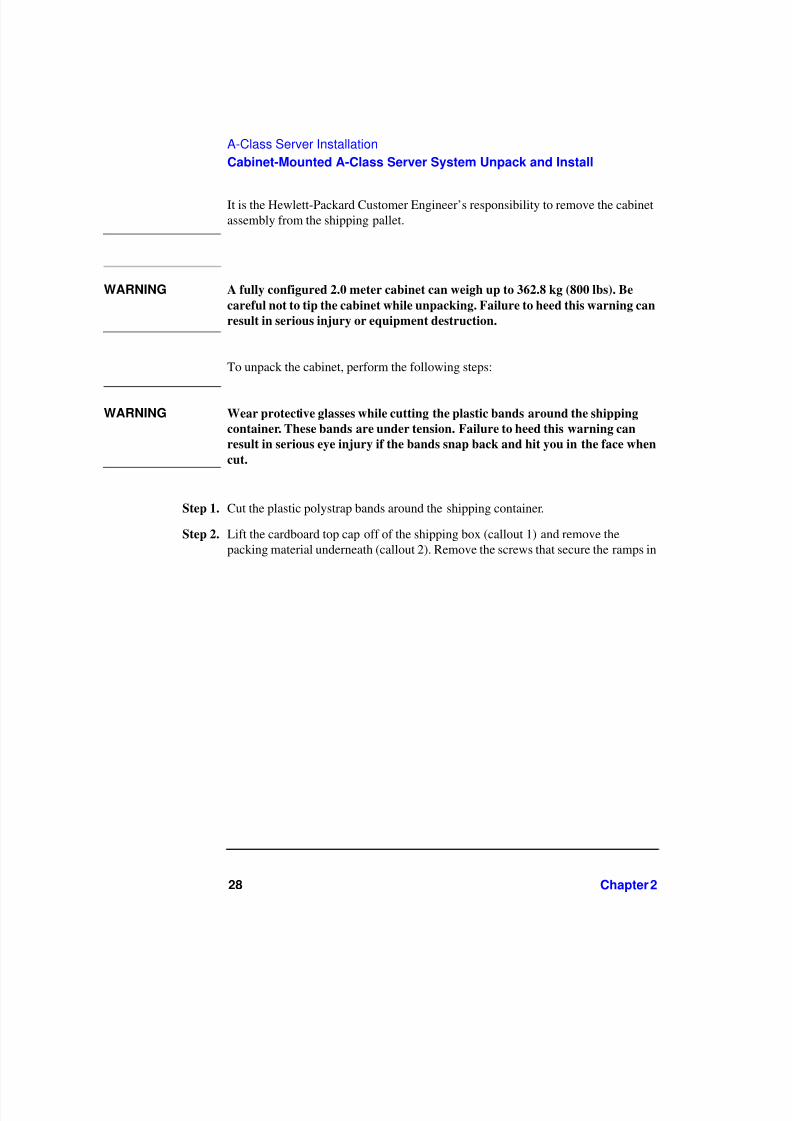
It is the Hewlett-Packard Customer Engineer’s responsibility to remove the cabinetassembly from the shipping pallet.
WARNING A fully configured 2.0 meter cabinet can weigh up to 362.8 kg (800 lbs). Be
careful not to tip the cabinet while unpacking. Failure to heed this warning can
result in serious injury or equipment destruction.
To unpack the cabinet, perform the following steps:
WARNING Wear protective glasses while cutting the plastic bands around the shipping
container. These bands are under tension. Failure to heed this warning can
result in serious eye injury if the bands snap back and hit you in the face when
cut.
Step 1. Cut the plastic polystrap bands around the shipping container.
Step 2. Lift the cardboard top cap off of the shipping box (callout 1) and remove thepacking material underneath (callout 2). Remove the screws that secure the ramps in

7/31/2019 A 180 Class Doc
http://slidepdf.com/reader/full/a-180-class-doc 29/122
Chapter 2 29
A-Class Server Installation
Cabinet-Mounted A-Class Server System Unpack and Install
place and lift the ramps out (callout 3).
1
2
3 3
3

7/31/2019 A 180 Class Doc
http://slidepdf.com/reader/full/a-180-class-doc 30/122
30 Chapter 2
A-Class Server Installation
Cabinet-Mounted A-Class Server System Unpack and Install
Step 3. Remove the brackets securing the cabinet to the pallet (callout 4).
Step 4. Insert the ramps in the notches provided on the pallet (callout 5). Remove the side
4
44

7/31/2019 A 180 Class Doc
http://slidepdf.com/reader/full/a-180-class-doc 31/122
Chapter 2 31
A-Class Server Installation
Cabinet-Mounted A-Class Server System Unpack and Install
panels from the cabinet and set them aside (callout 6).
WARNING
A fully configured 2.0 meter cabinet can weigh up to 362.8 kg (800 lbs). Always
use at least two people to roll the cabinet off of the pallet. Failure to heed this
warning can result in serious injury or equipment destruction.
Step 5. Use at least two people to roll the cabinet off of the pallet and down the ramp
5
5
5
6
6

7/31/2019 A 180 Class Doc
http://slidepdf.com/reader/full/a-180-class-doc 32/122
32 Chapter 2
A-Class Server Installation
Cabinet-Mounted A-Class Server System Unpack and Install
(callout 7).
Cabinet Inspection
Once the cabinet is off the shipping pallet, but before moving it to the installationsite, inspect the internal and external condition of the cabinet.
Cabinet Exterior Checklist:
Check the cabinet exterior for signs of shipping damage:
o Look at the top and sides for dents, warpage, or scratches.
o Check the front bezels for alignment, scratches, and that they open and closenormally.
o Check any filler panels on the front of the cabinet, for proper fit.
o Check the forehead assembly for any signs of damage.
o Check the rear door for dents, scratches, proper fit when its closed, andoperation.
Cabinet Interior Checklist: Open the rear door and inspect the inside of the
7

7/31/2019 A 180 Class Doc
http://slidepdf.com/reader/full/a-180-class-doc 33/122
Chapter 2 33
A-Class Server Installation
Cabinet-Mounted A-Class Server System Unpack and Install
cabinet:
o Inspect all cables, make sure they are secure.
o Inspect all rails for signs of damage.
o Check all mounting screws for tightness.
o Check all components for signs of shifting during shipment or any signs of damage.
NOTE If the shipment is incomplete, or if the equipment is damaged or fails to meetspecifications, notify the nearest Hewlett-Packard Sales and Support Office. If
damage occurred in transit, notify the carrier as well. Hewlett-Packard will arrangefor replacement or repair without waiting for settlement of claims against the carrier.If the shipment was damaged in transit, keep the shipping containers and packagingmaterial for inspection.
If extensive damage is found, it may be necessary to return the entire cabinet to HP.Refer to the Repacking instructions.
Cabinet Installation
Installation of a factory-loaded cabinet consists of the following steps:
Step 1. Move the cabinet to installation site.
Step 2. Lower the leveling feet. (This will prevent excessive wear on the casters.)
CAUTION Extend the cabinet stabilizers, located at the bottom of the front of the cabinet, as anadditional safeguard against overturning the cabinet during installation. Failure toobserve this precaution could result in personal injury or equipment damage.
Step 3. Connect the console and system peripherals to the server.
For information about connecting external devices, refer to “External Connections”at the end of this section.
NOTE Attaching cables while the rails are extended fully forward will ensure that

7/31/2019 A 180 Class Doc
http://slidepdf.com/reader/full/a-180-class-doc 34/122
34 Chapter 2
A-Class Server Installation
Cabinet-Mounted A-Class Server System Unpack and Install
sufficient slack is available for later maintenance.
Step 4. Connect the cabinet power cord to the appropriate wall outlet.
NOTE If the cabinet being installed contains a PowerTrust Uninterruptible Power Supply(UPS), perform the steps shown under the “PowerTrust UPS Option” subsection.
Step 5. Be sure all peripherals outside the cabinet are connected to wall outlets.
The cabinet/server system assembly is now ready for the power up process. Refer tothe section titled, “A-Class Server Power Up and Boot Procedures”.
PowerTrust UPS Option
Unpack the PowerTrust UPS and read all the installation information in thePowerTrust System Guide, part number 5961-8383. Once all the procedures listed inthe UPS guide are complete, perform the following steps to complete the UPSinstallation with the cabinet.
1. Position the UPS next to the cabinet on the floor.
2. Remove the jumper cord from the SPU to the PDU inside the cabinet.
3. Install one of the convenience cords (output cord) that came with the UPS intothe AC receptacle in the back of the SPU.
4. Place the other end of that cord into one of the Output outlets in the back of theUPS.
5. The other convenience cord is connected between the UPS and the systemconsole.
6. Locate the appropriate input line cord for the UPS in the supplemental packageshipped with the UPS.
7. Plug the UPS into the appropriate wall outlet.
8. The system should now be ready for power up. Refer to the section titled,“A-Class Server Power Up and Boot Procedures”.
Repackaging the Cabinet for Shipment
Use the original packing material to repackage the cabinet for shipment. If thepacking material is not available, contact your local Hewlett-Packard Sales and

7/31/2019 A 180 Class Doc
http://slidepdf.com/reader/full/a-180-class-doc 35/122
Chapter 2 35
A-Class Server Installation
Cabinet-Mounted A-Class Server System Unpack and Install
Support Office regarding shipment.
Before shipment, place a tag on the container (or equipment) to identify the ownerand the service to be performed. Include the equipment model number and the fullserial number, if applicable. The label showing the model number and the full serialnumber is located on the outside of the rear door.
Due to the weight of a fully loaded cabinet, it will require two people to push thecabinet up the ramp onto the pallet.
WARNING
Repackaging a loaded cabinet may be hazardous because a fully configured 2.0
meter cabinet can weigh up to 362.8 kg (800 lbs). Always use two people when
moving the cabinet and when positioning the cabinet on the pallet. Check the
condition of the loading/unloading ramp before use. If the ramp appears
damaged, DO NOT attempt to push a loaded cabinet up the ramp onto the
pallet. Contact your local Hewlett-Packard Sales and Support Office regarding
shipment. Failure to heed this warning can result in serious injury orequipment destruction.
To repackage the cabinet, follow the repacking checklist and refer to the unpackinginstructions for detail.
Repacking Checklist:
o Assemble the HP packing materials that came with the cabinet.
o Connect the loading ramp to the pallet.
o Raise the cabinet levelers before moving the cabinet.
o Push the cabinet up the ramp onto the pallet. Be sure to position the cabinet sothat the front goes up the ramp first.
o Secure the cabinet to the pallet with the shipping clamps, shipping block, andrear door support.
7/31/2019 A 180 Class Doc
http://slidepdf.com/reader/full/a-180-class-doc 36/122
36 Chapter 2
A-Class Server Installation
Cabinet-Mounted A-Class Server System Unpack and Install
o Place the anti-static bag over the cabinet.
o Place bezel support packing on the front corners of the cabinet. Secure it with awrap.
o Place the top cap packing material and loading/unloading ramp on top of thecabinet.
o Wrap the clam shell box around the cabinet.
o Put the box top on the box and secure the assembly to the pallet.
Be sure to follow the tagging and labeling instructions mentioned earlier. Thecabinet is now ready for shipment.
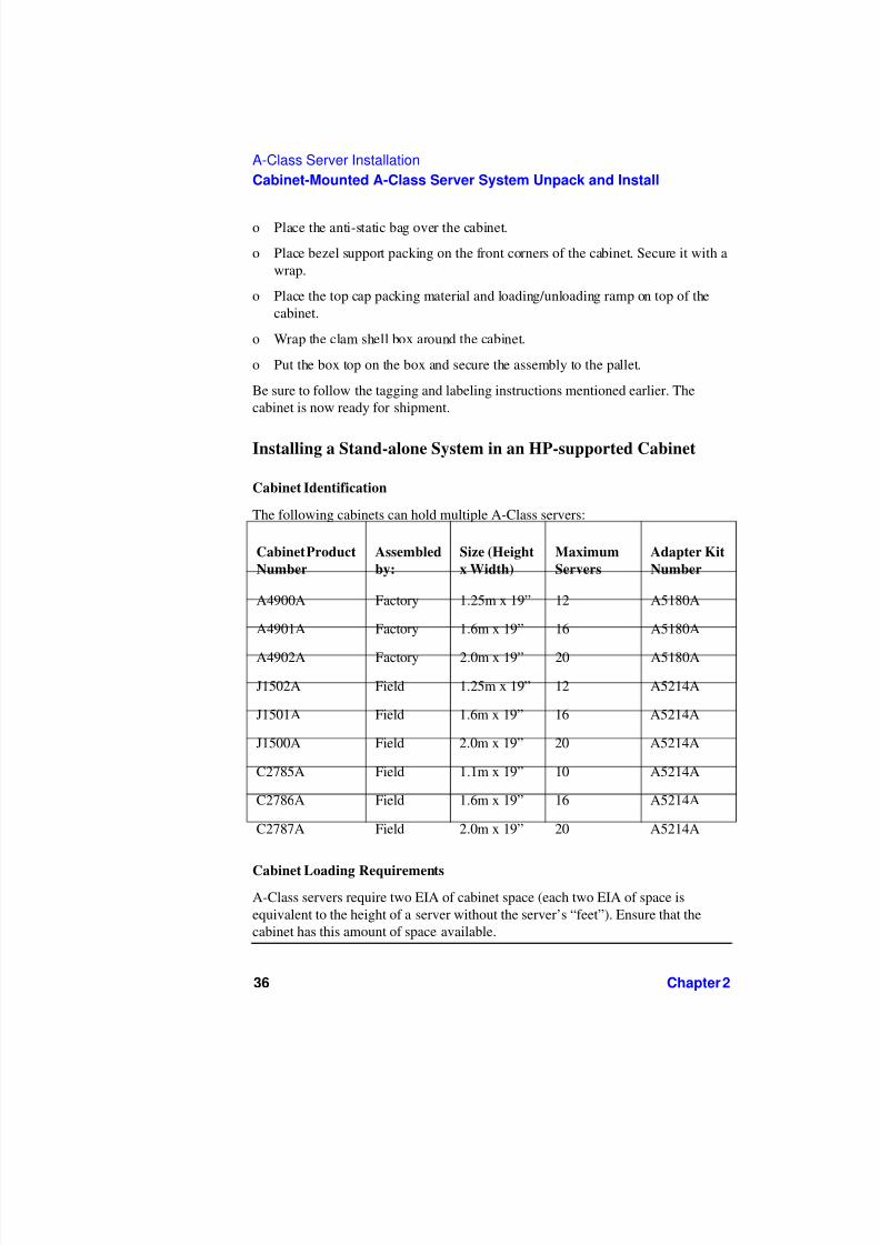
Installing a Stand-alone System in an HP-supported Cabinet
Cabinet Identification
The following cabinets can hold multiple A-Class servers:
Cabinet Loading Requirements
A-Class servers require two EIA of cabinet space (each two EIA of space isequivalent to the height of a server without the server’s “feet”). Ensure that thecabinet has this amount of space available.
Cabinet Product
Number
Assembled
by:
Size (Height
x Width)
Maximum
Servers
Adapter Kit
Number
A4900A Factory 1.25m x 19” 12 A5180A
A4901A Factory 1.6m x 19” 16 A5180A
A4902A Factory 2.0m x 19” 20 A5180A
J1502A Field 1.25m x 19” 12 A5214A
J1501A Field 1.6m x 19” 16 A5214A
J1500A Field 2.0m x 19” 20 A5214A
C2785A Field 1.1m x 19” 10 A5214A
C2786A Field 1.6m x 19” 16 A5214A
C2787A Field 2.0m x 19” 20 A5214A

7/31/2019 A 180 Class Doc
http://slidepdf.com/reader/full/a-180-class-doc 37/122
Chapter 2 37
A-Class Server Installation
Cabinet-Mounted A-Class Server System Unpack and Install
NOTE Replace the rubberized feet on the server with plugs provided in the cabinetmounting adapter kit.
Fill empty cabinets from the top down, with A-Class servers on top. If you aremounting one or more servers into an empty cabinet, start at the inside top of thecabinet and count down four of the holes in the columns at each corner to determinethe position of the rails for the first server. When the first rails are installed, continueto use the four hole requirement as your guide for installing additional A-Classservers.
Refer to the Rail Kit Installation Sheet (A5214-96001) for instructions necessary toinstall rails in the HP computer cabinet.
Mounting the Server To mount the server in the cabinet, follow the procedurelisted below:
Step 1. From the front of the cabinet, slide the server onto the rails. Push the server into thecabinet until approximately three inches of the server remains protruding from thefront.
Step 2. Install sheet metal nuts on the left and right front columns and align with frontanchor bracket slots.
Step 3. Install the left and right front anchor brackets on each side of the server as follows:
o Insert each hooked tab into its slot on the bottom of the front corner of theserver.

7/31/2019 A 180 Class Doc
http://slidepdf.com/reader/full/a-180-class-doc 38/122
38 Chapter 2
A-Class Server Installation
Cabinet-Mounted A-Class Server System Unpack and Install
o Hold the tabs upright and slide the server all the way into cabinet until the tabsbutt up against the columns on each side.
Step 4. Fasten the both front anchor brackets securely to both front cabinet columns withthe prepositioned sheet metal nuts.
Step 5. Attach a plastic end cap to each anchor bracket.
Step 6. At the rear of the cabinet, position the rear rail mounting clamps on each rail at theback of the server. Tilt each clamp forward slightly and slide the angled tabcompletely into the available slot in the server so that each clamp sits flat on the rail.

7/31/2019 A 180 Class Doc
http://slidepdf.com/reader/full/a-180-class-doc 39/122
Chapter 2 39
A-Class Server Installation
Cabinet-Mounted A-Class Server System Unpack and Install
Step 7. Fasten each rear mounting clamp to its rail with the screws provided.
When you are ready to connect external devices, refer to “External Connections” forfurther information.
External Connections
External devices are interfaced with the A-Class server by means of specificconnectors located in the rear of the server. Exterior connections to the serverinclude ports for:
• Small Computer System Interface (SCSI) devices
• System Consoles
• Local Area Networks (LANs)
• Power Cords.

7/31/2019 A 180 Class Doc
http://slidepdf.com/reader/full/a-180-class-doc 40/122
40 Chapter 2
A-Class Server Installation
Cabinet-Mounted A-Class Server System Unpack and Install
Connect External Small Computer System Interface (SCSI) Devices
Connect external SCSI devices to the Single Ended SCSI bus (labeled SCSI
(Single-Ended) 8/16/5) on the system card or to additional SCSI interface cards. If external devices will not be connected to the SCSI bus, make sure the terminator(1252-3932) is in place.
Make sure all devices on the SCSI bus have a unique address and the last device isterminated. Refer to the documentation accompanying each device to learn how toset addresses and where to place terminators.
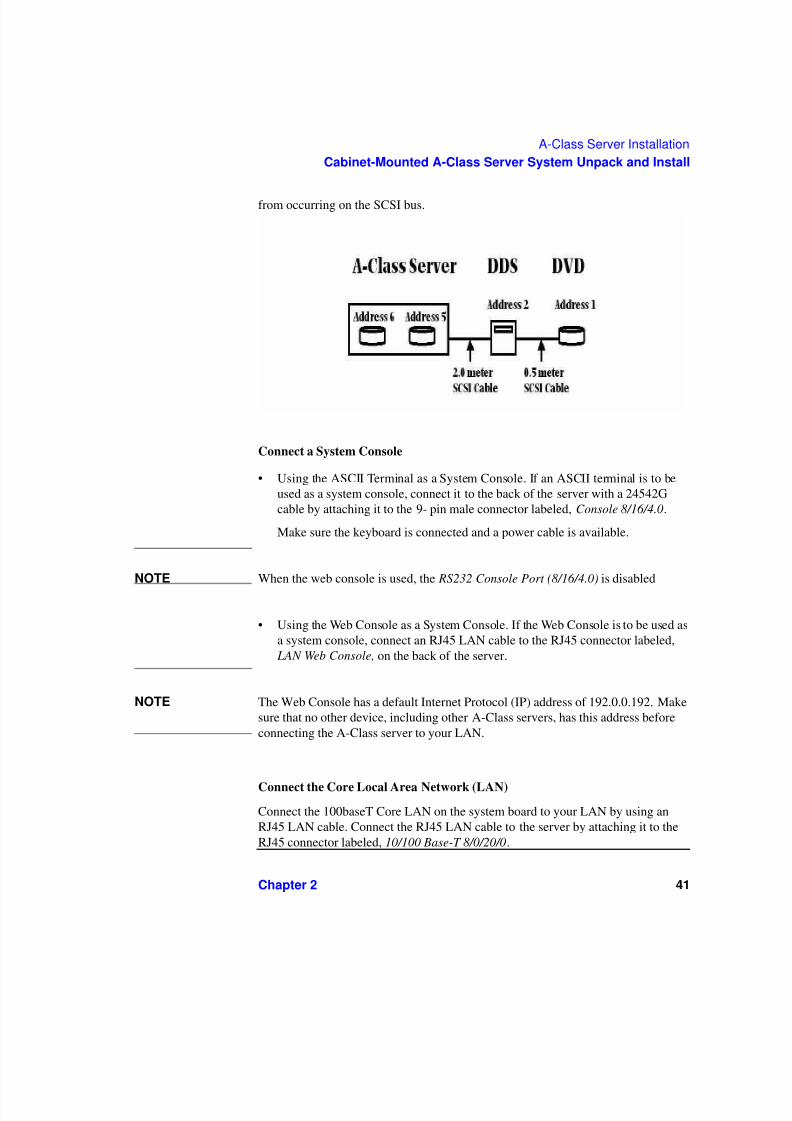
Connect external DDS (Digital Data Storage) tape and DVD/ CDROM drives toA-Class servers as shown in the diagram below. Connecting these devices in this
manner reduces the likelihood of excessive parity errors and unexpected interrupts
7/31/2019 A 180 Class Doc
http://slidepdf.com/reader/full/a-180-class-doc 41/122
Chapter 2 41
A-Class Server Installation
Cabinet-Mounted A-Class Server System Unpack and Install
from occurring on the SCSI bus.
Connect a System Console
• Using the ASCII Terminal as a System Console. If an ASCII terminal is to beused as a system console, connect it to the back of the server with a 24542Gcable by attaching it to the 9- pin male connector labeled, Console 8/16/4.0.
Make sure the keyboard is connected and a power cable is available.
NOTE When the web console is used, the RS232 Console Port (8/16/4.0) is disabled
• Using the Web Console as a System Console. If the Web Console is to be used asa system console, connect an RJ45 LAN cable to the RJ45 connector labeled, LAN Web Console, on the back of the server.
NOTE The Web Console has a default Internet Protocol (IP) address of 192.0.0.192. Makesure that no other device, including other A-Class servers, has this address beforeconnecting the A-Class server to your LAN.
Connect the Core Local Area Network (LAN)
Connect the 100baseT Core LAN on the system board to your LAN by using anRJ45 LAN cable. Connect the RJ45 LAN cable to the server by attaching it to theRJ45 connector labeled, 10/100 Base-T 8/0/20/0.

7/31/2019 A 180 Class Doc
http://slidepdf.com/reader/full/a-180-class-doc 42/122
42 Chapter 2
A-Class Server Installation
Cabinet-Mounted A-Class Server System Unpack and Install
Connect Power Cords
CAUTION Do not press and hold the Web Console Reset button (located on the rear of theserver between the LAN Web Console receptacle and the ASCII terminalreceptacle) while connecting the server power cord. Failure to observe thisprecaution will cause erasure of all settings in the Web Console that is connected tothe server.
Connect the power cord that is provided with the system to the server. Forstand-alone servers, the power cord will be localized to each country’s powerapplication. If an HP Uninterruptible Power Supply (UPS) is the power source, usethe power cord provided with the UPS. If an HSC Remote Management card isinstalled in the server, use the cable provided with the HP UPS to connect the RS232serial port to the port labeled “UPS” on the HSC Remote Management card.
Connect power cords to all external devices at this time with the localized powercord, cabinet power cord, or the UPS power cord.
For cabinet mounted servers, the server power cord connects to the C13 connectorof the Power Distribution Unit in the cabinet.

7/31/2019 A 180 Class Doc
http://slidepdf.com/reader/full/a-180-class-doc 43/122
Chapter 2 43
A-Class Server Installation
Installing Internal Add-On Components
Installing Internal Add-On Components
This section explains how to install internal add-on components into A-Classservers. Internal add-on components include memory, cache memory, embeddeddisks and I/O cards. For cabinet mounted servers, it is necessary to remove theserver from the cabinet to install internal add-on components.
Refer to the appropriate section for internal add-on component installationinformation:
“Information Sheet”
“Installing a Factory-integrated Cabinet”
“Installing a Stand-alone System in an HP-supported Cabinet”
“External Connections”
Installing Memory (RAM) Modules.
This section describes how to install memory (RAM) into A-Class servers.Computer memory is commonly referred to as Random Access Memory (RAM).The terms RAM and memory are used interchangeably in this documentation.Abbreviated Memory SIMM installation instructions also appear on the 11” x 14”maintenance label adhered to the bottom of the top cover.
A-Class memory is sold as a module. A module is defined as two SIMMs. A-Classservers support three memory module sizes: 128MB, 256MB and 512MB. The128MB memory module consists of two 64MB SIMMS. The 256MB memorymodule consists of two 128MB SIMMs and the 512MB memory module consists of two 256MB SIMMs. A memory module occupies two slots. The size (or capacity)of a memory SIMM is printed along the top edge of the SIMM.
NOTE SIMM is an acronym for Single Inline Memory Module. A SIMM has components

7/31/2019 A 180 Class Doc
http://slidepdf.com/reader/full/a-180-class-doc 44/122
44 Chapter 2
A-Class Server Installation
Installing Internal Add-On Components
on one side of the card, only.DIMM is an acronym for Dual Inline Memory Module.A DIMM has components on both sides of the card.The acronym SIMM will beused throughout this section to refer to either SIMM or DIMM.
A-Class servers provide 8 slots for memory. These slots are labeled in pairs and arenumbered 0a, 0b, 1a, 1b, 2a, 2b, 3a and 3b. The nomenclature for a pair of SIMMslots is 0a/b, 1a/b, 2a/b and 3a/b. The following rules govern the installationmemory in A-Class Servers.
• Memory must be installed in SIMM pairs.
• The capacity of SIMMs must be the same.
• Install SIMMs with the greatest capacity in the lowest slot numbers.
Follow the steps below to install memory in A-Class servers.
Electrostatic Discharge Precautions.
The procedures in this section require opening the server and exposing the system toelectrostatic discharge. Always observe all electrostatic precautions when workingwith components inside or out of the server. Failure to follow these precautions mayresult in component damage or loss of system reliability.
• Use a grounding mat and an anti-static wrist strap.
• Wear the anti-static wrist strap to ensure that any accumulated electrostaticcharge is discharged from your body to ground.
Before You Do Anything...
o Power down the system.
o Unplug the server.
NOTE Cabinet-mounted servers must be removed from the cabinet before proceeding.
o Remove the top of the server by unscrewing the knurled captive screws on eachside of the rear of the server. Slide the top back, lift it off, and set it aside.
Step 1. Document which size SIMMs are already installed and in which slots.

7/31/2019 A 180 Class Doc
http://slidepdf.com/reader/full/a-180-class-doc 45/122
Chapter 2 45
A-Class Server Installation
Installing Internal Add-On Components
Step 2. Determine the size of the memory SIMMs to be installed.
Step 3. If the capacity of the memory SIMMs to be installed is less than or equal to existingmemory, install the new SIMMs in the next available slots.
Step 4. If the capacity of the memory SIMMs to be installed is greater than existingmemory, remove all existing memory “External Connections”, install “ExternalConnections”, the largest capacity SIMMs first beginning with slot 0a/b. Continueto add SIMMs in this manner.
Step 5. Proceed to “External Connections”
Installing Cache Memory SIMMs.
This section describes how to install Cache Memory SIMMs into A-Class servers.Abbreviated Cache Memory SIMM installation instructions also appear on the 11” x14” maintenance label adhered to the bottom of the top cover.
A-Class Cache Memory is sold as a module. A module is defined as two SIMMs.A-Class servers support a single 1MB Cache Memory module. The 1MB CacheMemory module consists of two 512MB SIMMs. A Cache Memory moduleoccupies two slots. The size (or capacity) of the Cache Memory SIMM is printedalong the top edge of the SIMM.
NOTE SIMM is an acronym for Single Inline Memory Module. A SIMM has components
on one side of the card, only.DIMM is an acronym for Dual Inline Memory Module.A DIMM has components on both sides of the card.The acronym SIMM will beused throughout this section to refer to either SIMM or DIMM.
A-Class servers provide 2 slots for Cache Memory. The following rules govern theinstallation memory in A-Class Servers.
• Cache Memory must be installed in SIMM pairs.
• The capacity of SIMMs must be the same.
Follow the steps below to install Cache Memory in A-Class servers.
Electrostatic Discharge Precautions.
The procedures in this section require opening the server and exposing the system toelectrostatic discharge. Always observe all electrostatic precautions when working

7/31/2019 A 180 Class Doc
http://slidepdf.com/reader/full/a-180-class-doc 46/122
46 Chapter 2
A-Class Server Installation
Installing Internal Add-On Components
with components inside or out of the server. Failure to follow these precautions mayresult in component damage or loss of system reliability.
• Use a grounding mat and an anti-static wrist strap.
• Wear the anti-static wrist strap to ensure that any accumulated electrostaticcharge is discharged from your body to ground.
Before You Do Anything...
o Power down the system.
o Unplug the server.
NOTE Cabinet-mounted servers must be removed from the cabinet before proceeding.
o Remove the top of the server by unscrewing the knurled captive screws on eachside of the rear of the server. Slide the top back, lift it off, and set it aside.
Step 1. Install the first 512MB Cache Memory SIMM in either unoccupied slot.
Step 2. Install the second 512MB Cache Memory SIMM in the remaining unoccupied slot.
Step 3. Proceed to “External Connections”
Installing Embedded Disk Drives.
This section describes how to install embedded disk drives into A-Class servers.Abbreviated embedded disk drive installation instructions also appear on the 11” x14” maintenance label adhered to the bottom of the top cover.
A-Class servers support up to two embedded disk drives. As of April 2000, diskcapacities of 4GB, 9GB and 18GB are supported.
Follow the steps below to install embedded disk drives in A-Class servers.
Electrostatic Discharge Precautions.
The procedures in this section require opening the server and exposing the system toelectrostatic discharge. Always observe all electrostatic precautions when workingwith components inside or out of the server. Failure to follow these precautions mayresult in component damage or loss of system reliability.
• Use a grounding mat and an anti-static wrist strap.

7/31/2019 A 180 Class Doc
http://slidepdf.com/reader/full/a-180-class-doc 47/122
Chapter 2 47
A-Class Server Installation
Installing Internal Add-On Components
• Wear the anti-static wrist strap to ensure that any accumulated electrostaticcharge is discharged from your body to ground.
Before You Do Anything...
o Power down the system.
o Unplug the server.
NOTE Cabinet-mounted servers must be removed from the cabinet before proceeding.
o Remove the top of the server by unscrewing the knurled captive screws on eachside of the rear of the server. Slide the top back, lift it off, and set it aside.
Step 1. Remove the disk carrier by removing the slotted T15 TORX screw and slide the diskcarrier upward and toward the power supply.
Step 2. If an embedded disk is already installed, disconnect the power and data cables fromthat disk. Place the disk carrier on a ESD safe mat.
Step 3. Set address and configuration jumpers on the disk to be installed. The lower disk isusually the boot disk and the recommended address is 6. The upper disk isrecommended to be address 5. DO NOT use address 7 as this address is reserved forthe SCSI controller internal to the server. The SCSI controller address of 7 can notbe modified.
Step 4. Check configuration jumpers existing disks. Make sure the TERMINATIONENABLED jumper is removed.
NOTE The TERMINATION ENABLED jumper must be REMOVED on all embeddeddisk drives. Failure to remove this jumper will prevent the SCSI bus from operatingproperly. Symptoms include failing to boot from the embedded disk drives whenexternal devices are connected to the “SCSI (Single Ended) 8/16/5 path”.

7/31/2019 A 180 Class Doc
http://slidepdf.com/reader/full/a-180-class-doc 48/122
48 Chapter 2
A-Class Server Installation
Installing Internal Add-On Components
Step 5. Install the first embedded disk drive in the lower slot and the second embedded diskin the upper slot of the disk carrier. Orient the disk drive and the carrier such that thepower and data connectors on the disk drive are on the same side as the sheetmetaltabs. Slide the disk drive into the carrier and secure the disk drive to the disk carrierwith the four slotted T15 TORX screws that came with the disk drive.
Step 6. Attach power and data cables to the embedded disk drives.
Step 7. Install the disk carrier by inserting the two sheetmetal tabs on the disk carrier intothe cut-outs in the server chassis. Secure the disk carrier using the slotted T15TORX screw removed in step 1.
t the upper drive to ID to 5
t the lower drive to ID to 6

7/31/2019 A 180 Class Doc
http://slidepdf.com/reader/full/a-180-class-doc 49/122
Chapter 2 49
A-Class Server Installation
Installing Internal Add-On Components
Step 8. Proceed to “External Connections”
Installing Input/Output (I/O) Cards.
This section describes how to install I/O cards into A-Class servers. Abbreviatedembedded PCI I/O card installation instructions also appear on the 11” x 14”maintenance label adhered to the bottom of the top cover.
A-Class servers provide two slots for I/O cards. The cards which plug into theseslots can be Peripheral Component Interconnect (PCI), High Speed Connect (HSC)I/O cards or both (see photo below).
The following rules govern the installation of I/O cards:
• When present, the A3342A HSC Remote Management I/O card must beinstalled in the bottom slot.
• For one HSC and one PCI card configurations, the HSC card must be installed inthe bottom slot.
• For two HSC or two PCI cards, the load order does not matter.
NOTE When the A3342A HSC Remote Management card is installed, the console pathchanges from 8/16/4 to 8/4/0. This may prevent HP-UX from booting.
During selftest, server firmware detects the presence or absence of the A3342AHSC Remote Management card and will automatically direct server firmwareoutput to the appropriate path (8/4/0.0 when the A3342A is present, 8/16/4.0 whenthe A3342A is absent). These path changes are transparent to the physical console
which should be connected to the server via the connector labeled “Console8/16/4.0”. These path changes are also transparent to the server firmware‘CONSOLE PATH’ value. Server firmware will not change the ‘CONSOLE PATH’value. It is not necessary to manually change the ‘CONSOLE PATH’ value when

7/31/2019 A 180 Class Doc
http://slidepdf.com/reader/full/a-180-class-doc 50/122
50 Chapter 2
A-Class Server Installation
Installing Internal Add-On Components
installing or removing the A3342A. You may do so if you chose.
Example: A3342A is not installed. ‘CONSOLE PATH’ value is 8/16/4. Serverfirmware directs output to 8/16/4.0. Install A3342A. The ‘CONSOLE PATH’ valueis still 8/16/4 but server firmware directs output to 8/4/0.0. Where the console isconnected never changes.
NOTE When the A3342A HSC Remote Management card is installed, do not move theconsole cable from the server connector labeled “Console 8/16/4.0” to the 9-pinconnector on the A3342A HSC Remote Management card. This connector is forUPS use only.
While server firmware can automatically respond to presence or absence of theA3342A HSC Remote Management card, HP-UX can not. If HP-UX was installedwithout a A3342A HSC Remote Management card installed, the HP-UX path forthe console will be 8/16/4.0. If an A3342A HSC Remote Management card isinstalled, the path changes to 8/4/0.0. The driver for this path is mux2. If mux2 is notconfigured to be ‘in’, HP-UX will no longer communicate with the console. Thesymptom is that the server boots from the root disk, displays the following messagethen hangs;
Trying Primary Boot Path
------------------------
Booting
Boot IO Dependent Code (IODC) revision 144
HARD Booted.
ISL Revision A.00.38 OCT26, 1994
ISL booting hpux
Boot
:disk (8/16/5.6.0.0.0.0.0;0)/stand/vmunix

7/31/2019 A 180 Class Doc
http://slidepdf.com/reader/full/a-180-class-doc 51/122
Chapter 2 51
A-Class Server Installation
Installing Internal Add-On Components
3605260 + 327680 + 408736 start 0x16b2e8
To correct this condition, remove the A3342A Remote Management card, bootHP-UX, run SAM and configure the mux2 driver to be ‘in’. If necessary, refer to theweb-based information at “External Connections” for instructions on how toperform this task. The A3342A Remote Management card can be installed after themux2 driver has been verified to be ‘in’.
Follow the steps below to install I/O cards in A-Class servers.
Electrostatic Discharge Precautions.
The procedures in this section require opening the server and exposing the system toelectrostatic discharge. Always observe all electrostatic precautions when workingwith components inside or out of the server. Failure to follow these precautions mayresult in component damage or loss of system reliability.
• Use a grounding mat and an anti-static wrist strap.
• Wear the anti-static wrist strap to ensure that any accumulated electrostaticcharge is discharged from your body to ground.
Before You Do Anything...
o Power down the system.
o Unplug the server.
NOTE Cabinet-mounted servers must be removed from the cabinet before proceeding.
o Remove the top of the server by unscrewing the knurled captive screws on eachside of the rear of the server. Slide the top back, lift it off, and set it aside.
Step 1. If necessary, remove I/O card brackets. Refer to “Information Sheet”
Step 2. Carefully insert the I/O card into the backplane connector. The tab on the bulkheadwill slide into its slot in the chassis.
Step 3. Attach the card support guide to the front edge of the I/O card, hook the tab into itsslot, and secure the support guide with the mounting screw.
Step 4. Slide the bulkhead slotted tab up into position between the captive screw andchassis, and tighten the captive screw.

7/31/2019 A 180 Class Doc
http://slidepdf.com/reader/full/a-180-class-doc 52/122
52 Chapter 2
A-Class Server Installation
A-Class Server Power Up and Boot Procedures
A-Class Server Power Up and Boot Procedures
Overview
This Section discusses the following power up and boot procedures:
“Power Up All External Devices”
“Power Up the Server”
“Configuring the integrated A-Class Web Console”. This procedure includes:
“Configuring The Web Browser Host”
“Configure the Web Browser”
“Configure The integrated A-Class Web Console Software”
“Accessing the Secure Web Console”
Optional procedures for identifying external devices and mapping diagnostics:
“Boot to Initial System Loader (ISL) (Optional)”
“Run Online Diagnostic Environment (ODE) Mapper (Optional)”
The command to “Boot HP-UX” after running either of the preceding options is alsoincluded.
Power Up Procedures
Power Up All External Devices
Apply power to all external devices, such as additional disk drives, Universal PowerSupply, and Digital Data Storage. Observe that each device passes its own selftestand is ready for operation. Refer to the device-specific documentation as necessary.

7/31/2019 A 180 Class Doc
http://slidepdf.com/reader/full/a-180-class-doc 53/122
Chapter 2 53
A-Class Server Installation
A-Class Server Power Up and Boot Procedures
Power Up the Server
Apply power to the A-Class server by toggling the rocker power switch on the rearof the server from the 0 position to the 1 position. All of the front panel LEDs willilluminate for a moment, then turn off. Only the green power LED will remainilluminated until power is switched off. If the LEDs do not illuminate or the serverdoes not appear to power on, refer to “Boot HP-UX” (link to A-Class SystemService)
The server will automatically conduct a selftest and, upon completion, the firmwareMain Menu screen will be displayed at the system console. Only the power LEDshould be illuminated at this point.
If AUTOBOOT is enabled, the system will automatically try to boot HP-UX fromthe PRIMARY PATH. If you want to interrupt the boot process, press any key on thekeyboard within 10 seconds after the message, Hit any key to interruptthe boot sequence is displayed.
Configuring the integrated A-Class Web Console
CAUTION The integrated A-Class Web Console is preconfigured with IP address 192.0.0.192.Power-off any other devices with the same IP address before proceeding withintegrated A-Class Web Console configuration. Each A-Class server must beconfigured to the integrated A-Class Web Console with an individual IP address.
Failure to follow this precaution will result in unexpected behavior of the LocalArea Network (LAN).
Configuring The Web Browser Host
NOTE The A-Class server and the Web Browser Host must be on the same subnet.
Enter the following commands into either a DOS window or UNIX widow on thehost where the browser used to configure the integrated A-Class Web Console
resides:Step 1. Route add 192.0.0.192 <host IP address>.
Step 2. ping 192.0.0.192.

7/31/2019 A 180 Class Doc
http://slidepdf.com/reader/full/a-180-class-doc 54/122
54 Chapter 2
A-Class Server Installation
A-Class Server Power Up and Boot Procedures
If ping is unsuccessful, proceed to step 3.
If ping is successful, proceed to Configure the Web Browser.
Step 3. arp -s 192.0.0.192 <MAC_ address of integrated A-Class Web Console>.
Step 4. Repeat Step 2.
NOTE Using the arp command requires superuser capability.
The MAC address of the integrated A-Class Web Console appears on the rear label
of the server in a field entitled, “MAC Address.” The MAC address must be enteredin the correct format. For example:
PCs: 00-60-b0-22-3e-ae Unix workstations: 00:60:b0:22:3e:ae
CAUTION DO NOT enter the “LAN Station Address” value (located on the rear label) in placeof the “MAC Address” value (also located on the rear label). If the wrong number iserroneously entered, use the arp -d command to correct the entry.
Failure to follow this precaution will cause the integrated A-Class Web Console tomalfunction.
Configure the Web Browser
Enable Java™ on your Web browser (Internet Explorer™ version 3.02 or NetscapeNavigator™, version 3.01 or later).
Temporarily add 192.0.0.192 to the list of URLs in your browser proxyconfiguration (under options).
Configure The integrated A-Class Web Console Software
NOTE During the configuration of your Secure web console, you must construct an IPgateway in the “configure IP” screen. If you do not have a valid IP gateway, enter
the same IP address as you entered for the Secure integrated A-Class Web Console.
Access the integrated A-Class Web Console through your Web browser, located on

7/31/2019 A 180 Class Doc
http://slidepdf.com/reader/full/a-180-class-doc 55/122
Chapter 2 55
A-Class Server Installation
A-Class Server Power Up and Boot Procedures
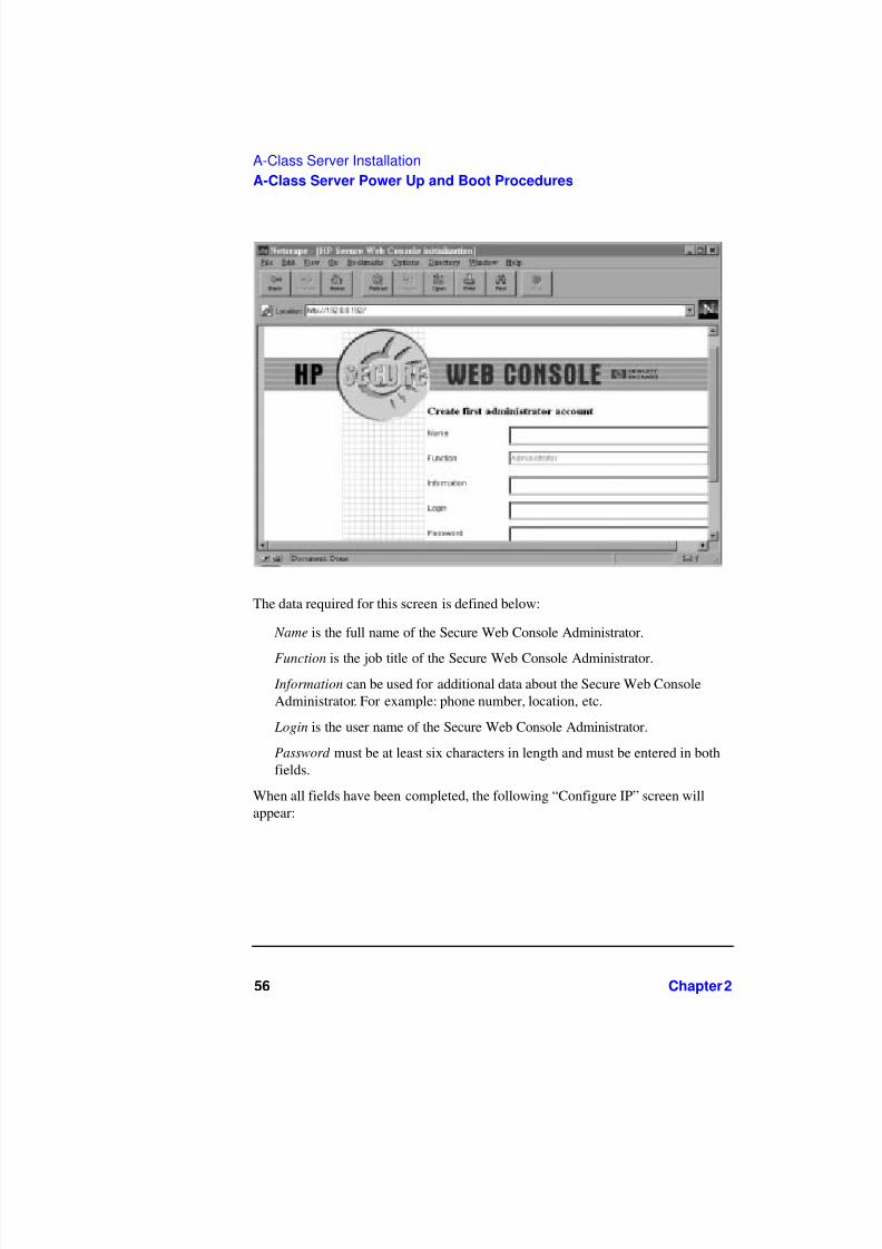
the same subnet, by typing the following URL in the “Location:” window:http://192.0.0.192. The screen shown below will be displayed:
Press OK to continue. The following administrator account creation screen willappear:
7/31/2019 A 180 Class Doc
http://slidepdf.com/reader/full/a-180-class-doc 56/122
56 Chapter 2
A-Class Server Installation
A-Class Server Power Up and Boot Procedures
The data required for this screen is defined below:
Name is the full name of the Secure Web Console Administrator.
Function is the job title of the Secure Web Console Administrator. Information can be used for additional data about the Secure Web ConsoleAdministrator. For example: phone number, location, etc.
Login is the user name of the Secure Web Console Administrator.
Password must be at least six characters in length and must be entered in bothfields.
When all fields have been completed, the following “Configure IP” screen willappear:

7/31/2019 A 180 Class Doc
http://slidepdf.com/reader/full/a-180-class-doc 57/122
Chapter 2 57
A-Class Server Installation
A-Class Server Power Up and Boot Procedures
The data required for this screen is defined below:• Secure Console Name (the name given to the integrated A-Class Web Console)
• IP address (the IP for the integrated A-Class Web Console port)
• IP subnet mask (the IP for the subnet mask for your site)
• IP gateway (the IP gateway address)
• System name (the name given to the A-Class Server).
After entering this information, press OK. The final screen in this series will appear:

7/31/2019 A 180 Class Doc
http://slidepdf.com/reader/full/a-180-class-doc 58/122
58 Chapter 2
A-Class Server Installation
A-Class Server Power Up and Boot Procedures
NOTE Disregard step 2, “Connect the serial cable from the system to the Secure Web
Console.” Step 2 applies only to the stand-alone version of the HP Secure WebConsole product. In A-class servers, this product is already installed internally.
Press OK to continue.
NOTE Pressing OK will NOT reboot the A-Class server. It will only reboot the Secure WebConsole. A-Class server boot procedures are included in the following section.
Accessing the Secure Web Console
Enter the IP address of the Web Console (the IP address is the address for the WebConsole port) in the web browser “Location:” window. Enter the user name andpassword, when prompted. From the HP Secure Web main screen, click on Access
Console.

7/31/2019 A 180 Class Doc
http://slidepdf.com/reader/full/a-180-class-doc 59/122
Chapter 2 59
A-Class Server Installation
A-Class Server Power Up and Boot Procedures
For additional information regarding the HP Secure Web Console, enter thefollowing URL: http://eproducts.hp.com/.
Configuring the Web Console
To configure the Web console for other A-Class servers, repeat all of the steps in thissection. Use arp -a to display arp entries and use arp-d to delete the previousentry for IP 192.0.0.192.
For example, to configure the Web Console for A-Class servers with MACaddresses of 0060b0a60ale and 001083a62a3e using a PC with an IP of 15.43.251.93, proceed as follows:
At the C:\> prompt, type: route add 192.0.0.192 15.43.251.93 and pressEnter.
Using the ping Command At the C:\> prompt, type: ping 192.0.0.192 andpress Enter.
The terminal will display: Pinging 192.0.0.192 with 32 bytes ofdata:
Request timed out.
Request timed out.
Request timed out.
Request timed out.
At the C:\> prompt, type: arp -s 192.0.0.192 00-60-b0-a6-0a-1e
At the C:\> prompt, type: ping 192.0.0.192 and press Enter.
The terminal will display: Pinging 192.0.0.192 with 32 bytes ofdata:
Reply from 192.0.0.192: bytes=32 time=10ms TTL=255
Reply from 192.0.0.192: bytes=32 time=10ms TTL=255
Reply from 192.0.0.192: bytes=32 time=10ms TTL=255
Reply from 192.0.0.192: bytes=32 time=10ms TTL=255
Return to “Configure the Web Browser” and “Configure The integrated A-ClassWeb Console Software”.
Using the arp -a Command At the C:\> prompt, type: arp -a and press Enter.
7/31/2019 A 180 Class Doc
http://slidepdf.com/reader/full/a-180-class-doc 60/122
60 Chapter 2
A-Class Server Installation
A-Class Server Power Up and Boot Procedures
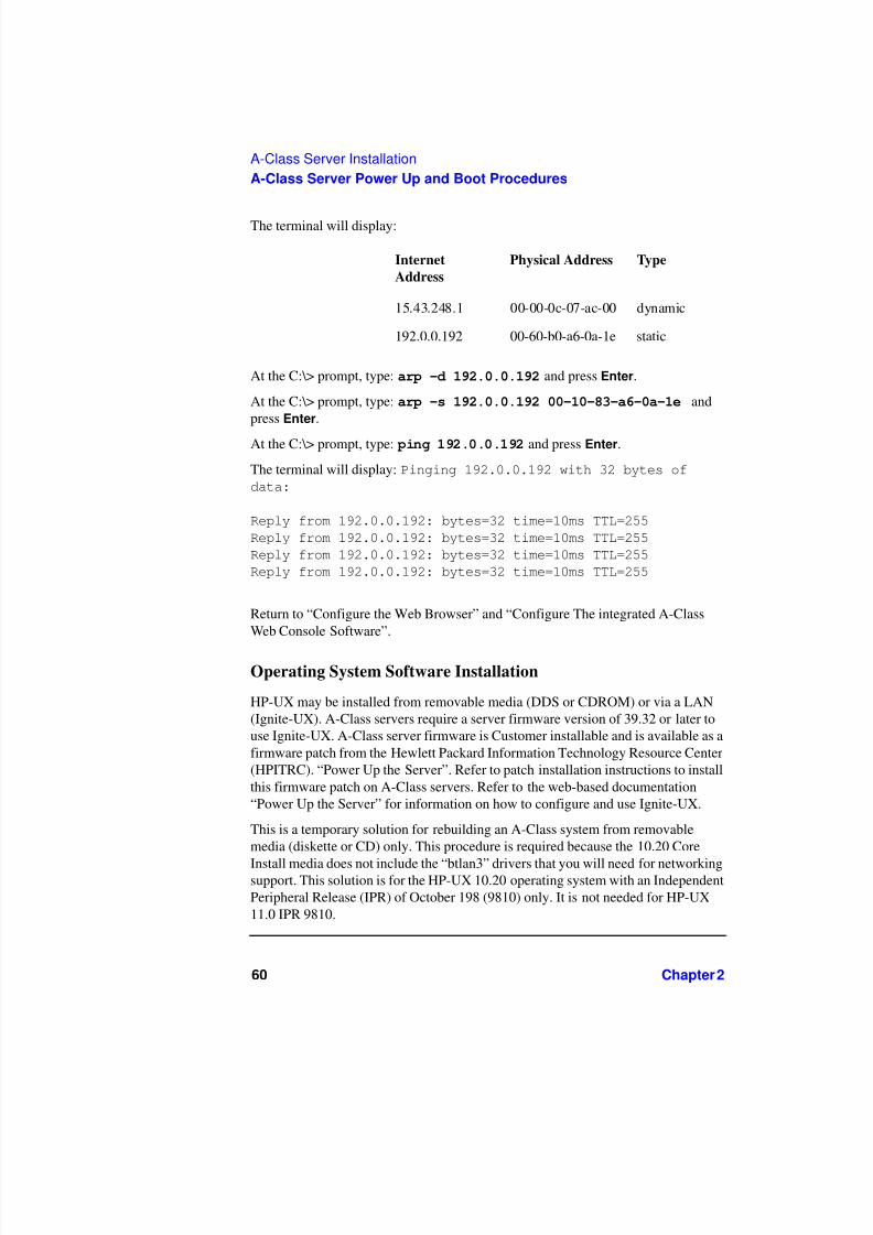
The terminal will display:
At the C:\> prompt, type: arp -d 192.0.0.192 and press Enter.
At the C:\> prompt, type: arp -s 192.0.0.192 00-10-83-a6-0a-1e andpress Enter.
At the C:\> prompt, type: ping 192.0.0.192 and press Enter.
The terminal will display: Pinging 192.0.0.192 with 32 bytes ofdata:
Reply from 192.0.0.192: bytes=32 time=10ms TTL=255
Reply from 192.0.0.192: bytes=32 time=10ms TTL=255
Reply from 192.0.0.192: bytes=32 time=10ms TTL=255
Reply from 192.0.0.192: bytes=32 time=10ms TTL=255
Return to “Configure the Web Browser” and “Configure The integrated A-ClassWeb Console Software”.
Operating System Software Installation
HP-UX may be installed from removable media (DDS or CDROM) or via a LAN(Ignite-UX). A-Class servers require a server firmware version of 39.32 or later touse Ignite-UX. A-Class server firmware is Customer installable and is available as afirmware patch from the Hewlett Packard Information Technology Resource Center(HPITRC). “Power Up the Server”. Refer to patch installation instructions to installthis firmware patch on A-Class servers. Refer to the web-based documentation“Power Up the Server” for information on how to configure and use Ignite-UX.
This is a temporary solution for rebuilding an A-Class system from removablemedia (diskette or CD) only. This procedure is required because the 10.20 Core
Install media does not include the “btlan3” drivers that you will need for networkingsupport. This solution is for the HP-UX 10.20 operating system with an IndependentPeripheral Release (IPR) of October 198 (9810) only. It is not needed for HP-UX11.0 IPR 9810.
Internet
Address
Physical Address Type
15.43.248.1 00-00-0c-07-ac-00 dynamic
192.0.0.192 00-60-b0-a6-0a-1e static

7/31/2019 A 180 Class Doc
http://slidepdf.com/reader/full/a-180-class-doc 61/122
Chapter 2 61
A-Class Server Installation
A-Class Server Power Up and Boot Procedures
Step 1. Install HP-UX 10.20 for HP 9000 series 800 servers from removable media:
• Load Core Install media into either CDROM or DDS.
• Change Alternate Path to match the path of the device containing the installmedia.
• Boot from alternate path
If you are using a DDS: The console will display:
Main Menu>
Type: co Press Enter.
The console will next display:
Configuration Menu>
Type: pa alt 8/16/5.0 Press Enter. The console will next display:
Configuration Menu>
Type: au bo on Press Enter. The console will next display:
Configuration Menu>
Type: bo alt Press Enter.
The following query will then be displayed:
Interact with IPL (Y, N, or Cancel)?
Type: no Press Enter.
The console will then display a menu. Select:
INSTALL HP-UX
Press Enter. The console will display another menu. Select:
STANDARD LVM CONFIGURATION
Press Enter. The console will display another menu. To the query:
INTERACT WITH SD-UX?
type: no Press Enter. The system will begin the software installation process.
Step 2. When installation is complete, the server will reboot and the console will display the

7/31/2019 A 180 Class Doc
http://slidepdf.com/reader/full/a-180-class-doc 62/122
62 Chapter 2
A-Class Server Installation
A-Class Server Power Up and Boot Procedures
following prompt:
Are you ready to link the system to a network?
Press Y or N then press return.
Type: n Press Enter.
When prompted by the console display, enter the time and system name. The servershould now function as a stand-alone system, except for an error in the /etc/rc.logfile stating that the program “swagentd” could not start. This is because the newkernel was not built with enough networking support to allow the SD-UX(swinstall) software to run since no valid network drivers (btlan3) were found on the10.20 media. To rebuild the kernel to allow the swinstall software to run, follow the
remainder of this procedure.Step 3. Log in as a “root” user and edit the “/stand/system” file to add the line: lan0.
When the system prompt “#” displays, type the following command:vi/stand/system Press Enter.
Step 4. To rebuild the kernel, type the following command at the “#” prompt: mk_kernel-o/stand/vmunix Press Enter.
NOTE Disregard the /usr/ccs/bin/ld: (Warning) “Linker features were used...” This warningdoes not apply to this procedure.
To reboot the system, type the following command when the system prompt “#”displays: reboot -r Press Enter.
Step 5. To make the SD-UX install software work, type the following command when thesystem prompt “#” displays:mknot/dev/lan0 c 52 0x000000 Press Enter. The SD-UX software shouldnow work properly.
Step 6. The following command string is for DDS installation of the XSW800HWECR1020(version XR41) bundle from removable media. This procedure will install the“btlan3” driver and reboot the server, but it will not automatically add “btlan3”support to the kernel. Type the following command when the system prompt “#”
displays:
swinstall -x autoreboot=true -x match_target=true
-s/dev/rmt/0m Press Enter. The “btlan3” driver will be installed and theserver will reboot.

7/31/2019 A 180 Class Doc
http://slidepdf.com/reader/full/a-180-class-doc 63/122
Chapter 2 63
A-Class Server Installation
A-Class Server Power Up and Boot Procedures
Step 7. To add “btlan3” driver support to the kernel, edit the /stand/system file and add theline: btlan3. To access the file, type the following command when the systemprompt “#” displays: vi /stand/system. When the file opens, add the “btlan3”line.
Step 8. Now, rebuild the kernel and reboot the system. Type the following command whenthe system prompt “#” displays: mk_kernel -o /stand/vmunix Press Enter.
NOTE Disregard the /usr/ccs/bin/ld: (Warning) “Linker features were used...” This warningdoes not apply to this procedure.
Then, type the following command when the system prompt “#” displays: reboot-r Press Enter. The system should now boot with an error-free /etc/rc.log file.
Step 9. Finally, type the following command when the system prompt “#” displays:/sbin/set_parms initial Press Enter. Network configuration is nowcomplete.
Boot Procedures
Boot to Initial System Loader (ISL) (Optional)
If you wish to verify that all external devices are identified by the server before
booting HP-UX:Step 1. Interrupt the boot process if AUTOBOOT is enabled.
Step 2. At the firmware Main Menu screen, type, bo pri.
Step 3. At the, Interact with IPL? prompt, type, y.
The ISL> prompt will be displayed.
Run Online Diagnostic Environment (ODE) Mapper (Optional)
Step 1. At the, ISL> prompt, type, ODE.
Step 2. At the, ODE> prompt, type, run mapper.
Compare the ODE Mapper output to the devices present. Address any discrepanciesbefore continuing. To exit ODE, type exit at the, ODE> prompt. This will returnyou to the, ISL> prompt.

7/31/2019 A 180 Class Doc
http://slidepdf.com/reader/full/a-180-class-doc 64/122
64 Chapter 2
A-Class Server Installation
A-Class Server Power Up and Boot Procedures
Boot HP-UX
• If the boot process was interrupted to run ODE Mapper, that process is resumedby typing, hpux at the, ISL> prompt.
• If the boot process was not interrupted, HP-UX will automatically boot.
For configuration of HP-UX, refer to http://eproducts.hp.com/.

7/31/2019 A 180 Class Doc
http://slidepdf.com/reader/full/a-180-class-doc 65/122
Chapter 2 65
A-Class Server Installation
A-Class Server System Software Configuration
A-Class Server System Software Configuration
Overview
Instructions for configuring software for both the A-Class server and the A-ClassSecure Web Console can be found at: http://eproducts.hp.com/.

7/31/2019 A 180 Class Doc
http://slidepdf.com/reader/full/a-180-class-doc 66/122
66 Chapter 2
A-Class Server Installation
A-Class Server System Software Configuration

7/31/2019 A 180 Class Doc
http://slidepdf.com/reader/full/a-180-class-doc 67/122
Chapter 3 67
A-Class System Service
3 A-Class System Service
aclassdoc00

7/31/2019 A 180 Class Doc
http://slidepdf.com/reader/full/a-180-class-doc 68/122
68 Chapter 3
A-Class System Service
A-Class System Repair
A-Class System Repair
Overview
The sections listed below describe the procedures you will use to identify faultconditions in your server, troubleshoot the system, exchange the server FieldReplaceable Units (FRUs), and configure system hardware:
“A-Class Server Fault Condition Recognition” Describes the LED patternsdisplayed during normal operation and when fault conditions occur.
“A-Class Server Trouble Shooting”. This section is divided into two levels:tasks that can be performed by customers and tasks that can only be performed
by qualified HP Field Service representatives.“A-Class Server Corrective Action”. Lists the subsections that containprocedures for “Ordering Repair Parts for the A-Class Server”, and removingand replacing the FRUs listed below:
“A-Class Server RAM Removal and Replacement”
“A-Class Server Cache Memory Removal and Replacement”
“A-Class Server Disk Drive Removal and Replacement”
“A-Class Server I/O Card Removal and Replacement”
“Replacing an A-Class Server Exchange Base Unit (EBU)”.

7/31/2019 A 180 Class Doc
http://slidepdf.com/reader/full/a-180-class-doc 69/122
Chapter 3 69
A-Class System Service
A-Class Server Fault Condition Recognition
A-Class Server Fault Condition Recognition
Overview
The existence of fault conditions are determined by reviewing Front Panel LEDStatus codes (shown below), or reviewing “Review Console Messages”.
The following subsections describe fault condition review procedures.
Review Front Panel Status LEDs
Front panel LEDs display either normal operation or fault status of the A-Classserver. Fault conditions consist of selftest failures and High Priority Machine Check(HPMC) fault conditions. The following table describes what the front panel LEDblink patterns indicate:
LAN LED Heartbeat LED Indication
Random Blink
Pattern
Heartbeat Blink
Pattern
Normal Operation (HP-UX running)
Off Off 2nd Level Cache SIMM fault
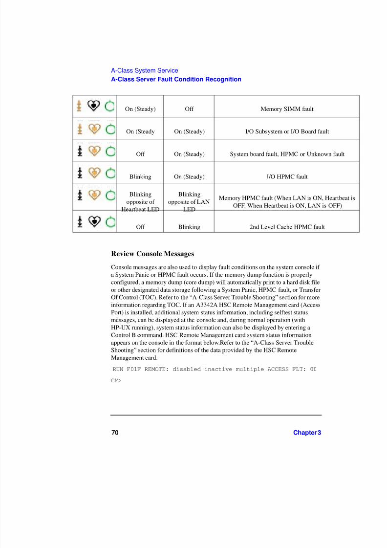
7/31/2019 A 180 Class Doc
http://slidepdf.com/reader/full/a-180-class-doc 70/122
70 Chapter 3
A-Class System Service
A-Class Server Fault Condition Recognition
Review Console Messages
Console messages are also used to display fault conditions on the system console if a System Panic or HPMC fault occurs. If the memory dump function is properlyconfigured, a memory dump (core dump) will automatically print to a hard disk file
or other designated data storage following a System Panic, HPMC fault, or TransferOf Control (TOC). Refer to the “A-Class Server Trouble Shooting” section for moreinformation regarding TOC. If an A3342A HSC Remote Management card (AccessPort) is installed, additional system status information, including selftest statusmessages, can be displayed at the console and, during normal operation (withHP-UX running), system status information can also be displayed by entering aControl B command. HSC Remote Management card system status informationappears on the console in the format below.Refer to the “A-Class Server TroubleShooting” section for definitions of the data provided by the HSC RemoteManagement card.
RUN F01F REMOTE: disabled inactive multiple ACCESS FLT: 00
CM>
On (Steady) Off Memory SIMM fault
On (Steady On (Steady) I/O Subsystem or I/O Board fault
Off On (Steady) System board fault, HPMC or Unknown fault
Blinking On (Steady) I/O HPMC fault
Blinkingopposite of
Heartbeat LED
Blinkingopposite of LAN
LED
Memory HPMC fault (When LAN is ON, Heartbeat isOFF. When Heartbeat is ON, LAN is OFF)
Off Blinking 2nd Level Cache HPMC fault

7/31/2019 A 180 Class Doc
http://slidepdf.com/reader/full/a-180-class-doc 71/122
Chapter 3 71
A-Class System Service
A-Class Server Trouble Shooting
A-Class Server Trouble Shooting
Overview
Troubleshooting an A-Class server is performed to the “Field Replaceable Unit”(FRU) level. Diagnostic testing can be performed on the A-Class server and mostcomponents can be removed and replaced by the customer or customerrepresentative.
NOTE The information in this section is meant for users who have at least a minimum levelof hardware troubleshooting experience. Some System Administrator-levelknowledge of the HP-UX operating system is also required.
This section gives you the information needed to recognize repeatable hardwarefailures that prevent completion of the server selftest, or hardware failures that willnot allow the HP-UX operating system to either initiate or complete the bootprocedure.
Use the troubleshooting data and procedures in this section to isolate hardwarefailures within the A-Class server. Do not use this information to troubleshootexternal peripheral device problems. Refer to the suspect peripheral's documentationfor troubleshooting assistance.
Procedures for evaluating and describing messages, codes, and indicators arecontained in the subsections listed below:
“A-Class Server Selftest Failures/Warnings”“Troubleshooting with Light-Emitting Diode (LED) Interpretation”
“Successful Power-on Selftest.”

7/31/2019 A 180 Class Doc
http://slidepdf.com/reader/full/a-180-class-doc 72/122
72 Chapter 3
A-Class System Service
A-Class Server Trouble Shooting
“Second Level Cache Memory Module Fault.”
“Random Access Memory (RAM) Module Fault.”
“I/O Subsystem or I/O Board Fault”
“System Board Fault, High Priority Machine Check (HPMC), or UnknownFault.”
“I/O HPMC Fault.”
“RAM HPMC Fault.”
“Firmware Warning Messages”
“Chassis Code Summary”
“Troubleshooting the ASCII Console”
“Troubleshooting the Secure Web Console”
“Troubleshooting Embedded Disks”
A-Class Server Selftest Failures/Warnings
A power-on selftest is conducted each time power is applied to the server. Failuresthat occur at this point will either prevent selftest from completing or, upon initialcompletion of selftest, display warnings on the console.
NOTE Warnings will include a brief description of the fault.
If the selftest fails before any output appears on the console, the three front panelLEDs (Power, Heartbeat, and LAN connection, shown below) will blink in patternsto identify which section of selftest failed. To troubleshoot selftest failures using thefront panel LEDs, proceed to the next section.
To troubleshoot selftest failures by chassis code analysis, refer to the “Chassis CodeSummary” section.

7/31/2019 A 180 Class Doc
http://slidepdf.com/reader/full/a-180-class-doc 73/122
Chapter 3 73
A-Class System Service
A-Class Server Trouble Shooting
Troubleshooting with Light-Emitting Diode (LED) Interpretation
The LED icons shown above are physically located on the right-hand side of theserver, when you are facing the front. The icon on the far right is a green circle that,under normal conditions, emits a steady light when server power is on. The middleicon of the three is an amber heart shape that emits, under normal conditions, a“heartbeat” blinking light when the server is operating normally. The left-most iconis also amber and represents the Local Area Network (LAN) signal. Under normalconditions, the LAN icon blinks irregularly as dictated by LAN signal activity.Additional selftest information is provided in the sub-sections that follow.
Successful Power-on Selftest.
When power is applied to the server, the green POWER icon will light uponsuccessful completion of the power supply selftest, which takes approximately 2seconds. If the green POWER LED fails to light, check the power source. If thepower source is valid, the problem is usually in the A-Class server power supply.Power supply failures are repaired by replacing the A-Class Exchange Base Unit(EBU). Refer to the “Replacing an A-Class Server Exchange Base Unit (EBU)”section. After the green POWER icon comes on, both the amber HEARTBEAT andamber LAN ACTIVITY icons will momentarily light and go out. When selftest iscomplete, the firmware Main Menu screen will display on the console, and the greenPOWER icon will emit a steady light. LED icon states will appear as shown below:
The following table shows how to interpret front panel LED blinking codes whenselftest has failed and the firmware Main Menu screen is inaccessible. During theconditions shown in this table, the green POWER icon is ON.
NOTE The LED pattern is only valid if the Firmware Main Menu is not displayed at theConsole.
Off Off On

7/31/2019 A 180 Class Doc
http://slidepdf.com/reader/full/a-180-class-doc 74/122
74 Chapter 3
A-Class System Service
A-Class Server Trouble Shooting
Second Level Cache/RAM Memory Module Faults
Second Level Cache Memory Module Fault. This fault occurs when a SecondLevel Cache (SLC) failure prevents the system from completing selftest. Chassiscodes provided by the HSC Remote Management card are useful in troubleshootingthis type of error. For example, the fault FLT 2120 chassis code message indicates:“Second Level cache selftest” failure.
NOTE SIMM is an acronym for Single Inline Memory Module. A SIMM has componentson one side of the card, only.DIMM is an acronym for Dual Inline Memory Module.
A DIMM has components on both sides of the card.The acronym SIMM will beused throughout this section to refer to either SIMM or DIMM.
LAN LED Heartbeat LED Indication
Random BlinkPattern
Heartbeat BlinkPattern
Normal Operation (Under HP-UX)
Off Off 2nd Level Cache SIMM fault
On (Steady) Off Memory SIMM fault
On (Steady On (Steady) I/O Subsystem or I/O Board fault
Off On (Steady) System board fault, HPMC or Unknown fault
Blinking On (Steady) I/O HPMC fault
Blinking oppositeof Heartbeat LED
Blinking oppositeof LAN LED
Memory HPMC fault (When LAN is ON, Heartbeat is OFFWhen Heartbeat is ON, LAN is OFF)
Off Heartbeat Blinkpattern
2nd Level Cache HPMC fault

7/31/2019 A 180 Class Doc
http://slidepdf.com/reader/full/a-180-class-doc 75/122
Chapter 3 75
A-Class System Service
A-Class Server Trouble Shooting
Electrostatic Discharge Precautions. The procedures in this section require opening theserver and exposing the system to electrostatic discharge. Always observe all electrostaticprecautions when working with components inside or out of the server. Failure to follow theseprecautions may result in component damage or loss of system reliability.
• Use a grounding mat and an anti-static wrist strap.
• Wear the anti-static wrist strap to ensure that any accumulated electrostatic charge isdischarged from your body to ground.
Before You Do Anything...
o Power down the system.
o Unplug the server.
NOTE Cabinet-mounted servers must be removed from the cabinet before proceeding.
o Remove the top of the server by unscrewing the knurled captive screws on each side of the rear of the server. Slide the top back, lift it off, and set it aside.
General SLC SIMM Troubleshooting.
NOTE A-Class servers can only use Cache Memory SIMMs with part number A5182-60002. UsingCache Memory SIMMs with any other part number may result in the server failing it’sselftest.
Step 1. Remove both SLC SIMMs and place on an ESD mat.
Step 2. Power up and observe LEDs
Step 3. If fault does not recur, the problem is with the SLC SIMMs. Either replace both SLC SIMMs,or proceed to the “Single SLC SIMM Troubleshooting.”subsection below.
Step 4. If the fault recurs, the problem is with the system board. To replace the system board, replacethe A-Class Exchange Base Unit (EBU). Refer to the “Replacing an A-Class ServerExchange Base Unit (EBU)” section.
Single SLC SIMM Troubleshooting. To troubleshoot SLC faults to a single SIMM, aknown-good SLC SIMM is required.
Step 1. Install the known-good SLC SIMM in slot A and install one of the original SLC SIMMs inslot B of the pair that failed. Power up and observe front panel LEDs.

7/31/2019 A 180 Class Doc
http://slidepdf.com/reader/full/a-180-class-doc 76/122
76 Chapter 3
A-Class System Service
A-Class Server Trouble Shooting
Step 2. If the fault does not recur, the problem was caused by the SIMM that is not presentlyinstalled. Boot the system and resume normal operations. If the fault recurs, proceed to step 3.
Step 3. Replace the SLC SIMM in slot B with the other original SLC SIMM. Power up and observefront panel LEDs.
Step 4. If the fault does not recur, the problem is with the SLC SIMM previously installed in slot B.Boot the system and resume normal operations.
Step 5. If the fault recurs, the problem is with the system board. To change the system board, youmust replace the A-Class Exchange Base Unit (EBU). Refer to the “Replacing an A-ClassServer Exchange Base Unit (EBU)” section.
Random Access Memory (RAM) Module Fault. This fault occurs when a RAM
failure prevents the system from completing selftest. Chassis codes provided by theHSC Remote Management card are useful in troubleshooting this type of error. Forexample, FLT 7xxx indicates a failure in the memory selftest.
NOTE SIMM is an acronym for Single Inline Memory Module. A SIMM has componentson one side of the card, only.DIMM is an acronym for Dual Inline Memory Module.A DIMM has components on both sides of the card.The acronym SIMM will beused throughout this section to refer to either SIMM or DIMM.
Electrostatic Discharge Precautions. The procedures in this section require opening theserver and exposing the system to electrostatic discharge. Always observe all electrostaticprecautions when working with components inside or out of the server. Failure to follow theseprecautions may result in component damage or loss of system reliability.
• Use a grounding mat and an anti-static wrist strap.
• Wear the anti-static wrist strap to ensure that any accumulated electrostatic charge isdischarged from your body to ground.
Before You Do Anything...
o Power down the system.
o Unplug the server.
NOTE Cabinet-mounted servers must be removed from the cabinet before proceeding.
o Remove the top of the server by unscrewing the knurled captive screws on each side of

7/31/2019 A 180 Class Doc
http://slidepdf.com/reader/full/a-180-class-doc 77/122
Chapter 3 77
A-Class System Service
A-Class Server Trouble Shooting
the rear of the server. Slide the top back, lift it off, and set it aside.
General RAM Module Troubleshooting.
Step 1. List which size SIMMs are installed in which slots.
Step 2. Remove all RAM SIMMs except for slot 0a and 0b (0a/b). Plug in and power up the server,and observe the front panel LEDs.
Step 3. If fault does not recur, the SIMMs installed in slot 0a and 0b are not the cause of the RAMSIMM fault. Power down the server, refer to the memory configuration list (step 1) and installthe next pair of SIMMs. Power up the server and observe the front panel LEDs.
Step 4. Repeat step 3 until the RAM SIMM fault recurs. Note which pair of SIMMs caused the RAMSIMM failure. Either replace both memory SIMMs or continue to troubleshoot to a singleSIMM.
For example: When RAM was reinstalled in slots 2a/b, the RAM SIMM fault returned.Therefore, the problem is with one of the two RAM SIMMs installed in slot 2a/b.
Single RAM Module Troubleshooting. To troubleshoot RAM faults to a single SIMM, aknown-good RAM SIMM is required.
Step 1. Install the known-good RAM SIMM in slot A and install one of the original RAM SIMMs inslot B. Power up the server and observe the front panel LEDs.
Step 2. If the fault does not recur, the problem was caused by the SIMM that is not presentlyinstalled. Boot the system and resume normal operations. If the fault recurs, proceed to step 3.
Step 3. Power down the server and replace the RAM SIMM in slot B with the other original RAMSIMM. Power up and observe front panel LEDs.
Step 4. If the fault does not recur, the problem is with the RAM SIMM that was previously installedin slot B. Boot the system and resume normal operations.
Step 5. If the fault recurs, the problem is with the system board. To change the system board, youmust replace the A-Class Exchange Base Unit (EBU). Refer to the “Replacing an A-ClassServer Exchange Base Unit (EBU)” section.
I/O Subsystem or I/O Board Fault
This fault occurs when either an HSC or PCI I/O board prevents the system fromcompleting selftest. Chassis codes provided by the HSC Remote Management cardare useful to troubleshoot this type of error. For example: FLT 8xxx indicates an I/O
card failure.To troubleshoot I/O Subsystem or I/O Board Faults using the front panel LEDs,follow the procedure listed below:
7/31/2019 A 180 Class Doc
http://slidepdf.com/reader/full/a-180-class-doc 78/122
78 Chapter 3
A-Class System Service
A-Class Server Trouble Shooting
Electrostatic Discharge Precautions. The procedures in this section requireopening the server and exposing the system to electrostatic discharge. Alwaysobserve all electrostatic precautions when working with components inside or out of the server. Failure to follow these precautions may result in component damage orloss of system reliability.
• Use a grounding mat and an anti-static wrist strap.
• Wear the anti-static wrist strap to ensure that any accumulated electrostaticcharge is discharged from your body to ground.
Before You Do Anything...
o Power down the system.o Unplug the server.
NOTE Cabinet-mounted servers must be removed from the cabinet before proceeding.
o Remove the top of the server by unscrewing the knurled captive screws on eachside of the rear of the server. Slide the top back, lift it off, and set it aside.
Step 1. Document the I/O configuration (write down which type of I/O board is installed inwhich of the I/O slots).
Step 2. Remove all I/O boards. Power up the server and observe the front panel LEDs.Step 3. If the fault does not recur and only a single I/O board was removed, that I/O card is
the cause of the I/O Subsystem or I/O Board Fault. Replace that I/O board, power onthe server, and observe the front panel LEDs. If the problem recurs, proceed to step8.
Step 4. If the fault does not recur and two I/O boards were removed, install the bottom I/Ocard, power up the server, and observe the front panel LEDs.
Step 5. If the fault recurs, the I/O card in the bottom slot is the cause of the I/O Subsystemor I/O Board Fault. Replace that I/O board.
Step 6. If the fault does not recur, install the second I/O card, power up the server, and
observe the front panel LEDs.Step 7. If the problem recurs, replace the top I/O card.
Step 8. If replacing the I/O card does not clear the I/O Subsystem or I/O Board Fault, theproblem is with the system board. To change the system board, you must replace the

7/31/2019 A 180 Class Doc
http://slidepdf.com/reader/full/a-180-class-doc 79/122
Chapter 3 79
A-Class System Service
A-Class Server Trouble Shooting
A-Class Exchange Base Unit (EBU). Refer to the “Replacing an A-Class ServerExchange Base Unit (EBU)” section.
System Board Fault, High Priority Machine Check (HPMC), or Unknown
Fault.
This fault occurs when the system board has an irrecoverable fault or an HPMCprevents the system from completing selftest. Chassis codes provided by the HSCRemote Management card are useful for troubleshooting this type of error, becauseHPMCs generate many chassis codes and some chassis codes indicate a specificfault.
To troubleshoot I/O Subsystem or I/O Board Faults, power on the server and
observe both the front panel LEDs and the console. If the server does not boot to thepoint where output displays on the console, the system board is the problem. Tochange the system board, you must replace the A-Class Exchange Base Unit (EBU).Refer to the “Replacing an A-Class Server Exchange Base Unit (EBU)” section.
If power cycling the server clears the fault, continue troubleshooting by entering the“ser pim” command at the firmware main menu screen. Check the timestamp on thePIM data to see if the time recorded corresponds to the time of the failure. Forassistance with decoding an HPMC, contact Hewlett-Packard.
I/O HPMC Fault.
I/O Subsystem or I/O Board faults occur when an HPMC, in response to an I/Ofailure, prevents the system from completing selftest. Chassis codes provided by theHSC Remote Management card are useful in troubleshooting this type of error,because HPMCs generate many chassis codes and some chassis codes indicate aspecific fault. To troubleshoot an I/O HPMC fault, refer to the “I/O Subsystem orI/O Board Fault” section.
If power cycling the server clears the fault, continue troubleshooting by using the“ser pim” command at the firmware main menu screen. Check the timestamp on thePIM data to see if the time recorded corresponds to the time of the failure. Forassistance with decoding an HPMC, contact Hewlett-Packard.
RAM HPMC Fault.
RAM faults occur when an HPMC, in response to a RAM failure, prevents the
system from completing selftest. Chassis codes provided by the HSC RemoteManagement card are useful in troubleshooting this type of error. To troubleshoot aRAM HPMC fault, refer to the “Random Access Memory (RAM) Module Fault.”section.

7/31/2019 A 180 Class Doc
http://slidepdf.com/reader/full/a-180-class-doc 80/122
80 Chapter 3
A-Class System Service
A-Class Server Trouble Shooting
If power cycling the server clears the fault, continue troubleshooting by using the“ser pim” command at the firmware main menu screen. Check the timestamp on thePIM data to see if the time recorded corresponds to the time of the failure. Forassistance with decoding an HPMC, contact Hewlett-Packard.
Second Level Cache Memory HPMC Fault.
SLC faults occur when an HPMC, in response to a SLC failure, prevents the systemfrom completing selftest. Chassis codes provided by the HSC Remote Managementcard are useful in troubleshooting this type of error.
If power cycling the server clears the fault, continue troubleshooting by using the“ser pim” command at the firmware main menu screen. Check the timestamp on the
PIM data to see if the time recorded corresponds to the time of the failure. Forassistance with decoding an HPMC, contact Hewlett-Packard.
Firmware Warning Messages
Firmware is the name given to the system boot instructions and selftest software thatis imbedded into a computer chip instead of stored on disk. Firmware also includeswarnings and error messages that are displayed on the console when selftest finds anerror. Those warnings and messages, and a brief description or action requirement of each, is shown in the table included below:
Firmware Warning Messages Description/Action Required
WARNING: Stop boot flag set. System cannot boot. This message accompanies those warnings thatprevent the system from booting. Look up theaccompanying message and take appropriateaction.
WARNING: Not enough memory to boot the OS. Ensure that the minimum amount of memory isinstalled
WARNING: Setting DEFAULTS has failed. The MFIOC chip failed. This failure requiresreplacing the EBU.
WARNING: Memory has been initialized but nottested as a result of FASTBOOT being enabled. To
test memory, use the 'FASTBOOT' command in theCONFIGURATION menu and reboot the system.
Disable FASTBOOT by the 'Fastboot OFF'command in the CONFIGURATION menu and
reboot.
WARNING: The processor has failed selftest due to aco-processor failure.
This condition requires replacing the EBU.

7/31/2019 A 180 Class Doc
http://slidepdf.com/reader/full/a-180-class-doc 81/122
Chapter 3 81
A-Class System Service
A-Class Server Trouble Shooting
Chassis Code Summary
Operating Status (OSTAT) and chassis codes are generated by A-Class serverfirmware. OSTAT and chassis codes can be read from stored locations or viewed'real time' via the HSC Remote Management card.
Chassis codes displayed during selftest only appear at the console. They will appearon either the ASCII console or the Web console. Below is an example of howchassis codes appear in response to a 'control b' key sequence:
WARNING: The processor has failed selftest. A processor selftest failure requires replacing theEBU.
WARNING: One or more memory banks were notconfigured due to a SIMM size mismatch or a SIMMfailure. For more details, use the MEMORYcommand in the INFORMATION menu.
Use the MEMORY command in theINFORMATION menu to determine correctconfiguration.
WARNING: The Bus Converter has failed. A Bus Converter failure requires replacing theEBU.
WARNING: FAN FAILURE HAS BEENDETECTED. THE SYSTEM WILL BEPOWERING DOWN. PLEASE CALL YOURSERVICE REPRESENTATIVE
A chassis fan failure requires replacing the EBU.
ERROR: A3342A AP Card must be in bottom slotonly.
Move the AP A3342A card to the bottom slot.
ERROR: HSC card in wrong slot. Move to bottomslot.
A mix of HSC and PCI cards has been detected.The HSC card must be installed in the bottomslot.
Firmware Warning Messages Description/Action Required

7/31/2019 A 180 Class Doc
http://slidepdf.com/reader/full/a-180-class-doc 82/122
82 Chapter 3
A-Class System Service
A-Class Server Trouble Shooting
The HSC Remote Management card shows status information on the console justabove the function key display (shown above) and is followed by the CM> prompt.The information displayed is shown below:
CM>
OSTAT Chassis
Code
REMOTE: sta
tus
activ
ity
password ACCESS FAULT:

7/31/2019 A 180 Class Doc
http://slidepdf.com/reader/full/a-180-class-doc 83/122
Chapter 3 83
A-Class System Service
A-Class Server Trouble Shooting
HSC Remote Management status information is defined as follows:
For more information on the HSC Remote Management card, refer to the HSC
Remote Management/Access Port Card information in the Reference section.During selftest, OSTAT and chassis codes are generated and stored by the serverfirmware. These chassis codes can be viewed even if an HSC Remote Managementcard is not installed. To view power on chassis codes, either type ser cc at thefirmware main menu, or change to the Service Menu and type cc.
A display of OSTAT and chassis codes are shown in the following example:
Chassis codes used in conjunction with the OSTAT value represent the status of thesystem:
Service Menu: Enter command > cc
CHASSIS CODES INFORMATION
Chassis Code
Status Code Definition
OSTAT Operating STATus. Values can be OFF, FLT, TEST,INIT, SHUT, WARN RUN and ALL.
Chassis A four digit field used in conjunction with OSTAT toidentify system status. The first digit of a chassis code isthe Major Code Category value.
REMOTE: REMOTE modem port. Three fields describe theRemote modem port.
• enabled/disabled: Remote modem port is connectedor not connected.
• active/inactive: Remote modem port is working oridle.
• single/multiple: Number of attempts to enter thepassword.
ACCESSFAULT:
Number of failed attempts to access the HSC RemoteManagement Card.

7/31/2019 A 180 Class Doc
http://slidepdf.com/reader/full/a-180-class-doc 84/122
84 Chapter 3
A-Class System Service
A-Class Server Trouble Shooting
INIT C4CC
INIT C4CD
INIT 3002
TEST 30BC
INIT 30BC
INIT C300
TEST 1030
<Press any key to continue (q to quit)> q
Service Menu: Enter command >
• OSTAT values of TEST and INIT are common during selftest.
• OSTAT values of RUN and SHUT are common when the HP-UX operatingsystem is running.
• OSTAT values FLT, OFF, and WARN are used to indicate when the serverfirmware has failed a test or detected a problem that does not keep selftest fromfinishing.
If a fault prevents the server from completing selftest, the OSTAT FLT is used andthe Chassis Code displays the test number that failed. If the server stops responding
while performing a test, the OSTAT value will be INIT or TEST and the chassiscode represents the test that was running when the server failed.
Refer to the table below to determine which tests were active when the system eitherfaulted or stopped responding during selftest, and the corrective action to take inresponse to the problem.
Major Code
Category
Description Corrective Action
1xxx CPU/TLB Tests Refer to “Replacing an A-Class Server Exchange BaseUnit (EBU)”
2xxx SLC Tests Refer to “Second Level Cache Memory Module Fault.”
3xxx PDH Tests Refer to “Replacing an A-Class Server Exchange BaseUnit (EBU)”

7/31/2019 A 180 Class Doc
http://slidepdf.com/reader/full/a-180-class-doc 85/122
Chapter 3 85
A-Class System Service
A-Class Server Trouble Shooting
4xxx Late Selftest Refer to “Replacing an A-Class Server Exchange BaseUnit (EBU)”
5xxx Bus Transactions Refer to “I/O Subsystem or I/O Board Fault”
6xxx Unused NA
7xxx Memory Tests Refer to “Second Level Cache/RAM Memory ModuleFaults”
8xxx I/O Device Codes Refer to “I/O Subsystem or I/O Board Fault”9xxx Console Initialization Refer to “Troubleshooting the ASCII Console” or
“Troubleshooting the Secure Web Console”
Axxx Boot Device Initialization Refer to “Troubleshooting Embedded Disks”
Bxxx O.S. Panic Codes Refer to http://eproducts.hp.com for Operating SystemFaults and Recovery
C2xx Memory Initialization Refer to “Second Level Cache/RAM Memory ModuleFaults”
C3xx Extended processor tests Refer to “Replacing an A-Class Server Exchange Base
Unit (EBU)”C4xx andC6xx
Console Init. Refer to “Troubleshooting the ASCII Console” or“Troubleshooting the Secure Web Console”
C5xx Primary Path Boot Codes Refer to “Troubleshooting Embedded Disks”
C7xx Non-Primary Path Boot Codes Refer to “I/O Subsystem or I/O Board Fault”
C8xx - CAxx Unused NA
CB0x TOC Codes Refer to http://eproducts.hp.com for Operating SystemFaults and Recovery
CBxx HPMC Codes Contact HP
CDxx Bus Init Refer to “I/O Subsystem or I/O Board Fault”
Dxxx O.S. Shutdown Codes Refer to http://eproducts.hp.com f or Operating SystemFaults and Recovery
Major Code
Category
Description Corrective Action

7/31/2019 A 180 Class Doc
http://slidepdf.com/reader/full/a-180-class-doc 86/122
86 Chapter 3
A-Class System Service
A-Class Server Trouble Shooting
Troubleshooting the ASCII Console
The ASCII Console is typically a “dumb” monochrome terminal that serves as thecommunication link between the A-Class server and the system operator. At poweron, the server’s selftest software tests server internal components and externalperipherals to determine the operational status of each. The ASCII Console displaysthe operational status of all components and peripherals, including its own, on theconsole screen. The screen will display selftest data output in one of two ways:
If an HSC Remote Management card is installed, the output appears at thebottom of the screen and is updated until selftest is complete and the firmwareMain Menu screen appears.
If an HSC Remote Management card is not installed, there will be no output tothe console screen until selftest completes.
If the ASCII console does not respond to input or does not display any output:• Make sure that the ASCII console is correctly connected to the server. Refer to
Chapter 2.
• Make sure that the LAN Web Console is NOT connected. If it is, instead of going to the ASCII console, output will re-directed to the LAN Web Console.
• Make sure the keyboard is correctly connected to the ASCII console.
• Cycle power to the ASCII console.
• Return configuration settings to default by pressing the appropriate soft keys onthe keyboard. Consult the Operator’s Manual for the specific soft keys to pressand the correct sequence. When the correct soft key sequence is entered, theDATACOM settings will be:
Exxx O.S. Warning Codes Refer to http://eproducts.hp.com for Operating SystemFaults and Recovery
Fxxx OS Run Codes Refer to http://eproducts.hp.com for Operating SystemFaults and Recovery
Major Code
Category
Description Corrective Action
Baud: 9600 Parity/DataBits: None/8 EnqAck: Yes
Asterisk: OFF Chk Parity: No SR(CH): Lo

7/31/2019 A 180 Class Doc
http://slidepdf.com/reader/full/a-180-class-doc 87/122
Chapter 3 87
A-Class System Service
A-Class Server Trouble Shooting
• Make sure REMOTE MODE is ON (asterisk appears in REMOTE MODE blockon the screen) and AUTO Line Feed is OFF (asterisk does NOT appear inAUTO LF block on the screen)
• Replace the ASCII console with a known good console.
• Try the LAN Web console. If the LAN Web console works but the ASCIIconsole does not, or neither console works, the system board is the problem. Tochange the system board, you must replace the A-Class Exchange Base Unit(EBU). Refer to the “Replacing an A-Class Server Exchange Base Unit (EBU)”section.
If you have an HSC Remote Management card installed and the ASCII consoleworks but the control B function does not, check the position of theSERVICE/NORMAL switch on the HSC Remote Management card. This switchmust be in the SERVICE position to enable the control B function. If the control Bfunction does not restore, replace the HSC Remote Management card. Refer to the“A-Class Server I/O Card Removal and Replacement” section.
NOTE The control B function is unique to the HSC Remote Management card. If you donot have an HSC Remote Management card installed, the control B function is notavailable.
Troubleshooting the Secure Web Console
The Secure Web Console is typically a “dumb” monochrome terminal that can serveas the communication link between the A-Class server and the system operator, as asubstitute for the ASCII Console. At power on, the server’s selftest software testsserver internal components and external peripherals to determine the operationalstatus of each. The Secure Web Console displays the operational status of allcomponents and peripherals, including its own, on the console screen. The screenwill display selftest data output in one of two ways:
If an HSC Remote Management card is installed, the output appears at the
bottom of the screen and is updated until selftest is complete and the firmwareMain Menu screen appears.
If an HSC Remote Management card is not installed, there will be no output tothe console screen until selftest completes.
RecvPace: Xon/Xoff XmitPace: None CS(CB)Xmit: No

7/31/2019 A 180 Class Doc
http://slidepdf.com/reader/full/a-180-class-doc 88/122
88 Chapter 3
A-Class System Service
A-Class Server Trouble Shooting
NOTE The Integrated LAN Web Console will be referred to as the Web console in thissection.
The A-Class server front panel LEDs do not indicate Web console failures. Thereare no blinking codes to show the source of a web console fault.
To troubleshoot the Web console:
1. Make sure that a LAN cable is inserted into the LAN Web Console connector onthe rear of the server. Refer to Chapter Two.
2. Log in to the Web console as the Administrator and check the DATACOMconfiguration. It should be:
NOTE Remember to use SAVE to retain any changes that you make.
3. Reset the Web console.
a. Type the IP address of the Web console in your web browser’s locationwindow and press Enter.
b. When the Web console page appears, log in.
c. Click on the Reset Web Console option.
NOTE Resetting the Web console will log any other users off of the system.
4. Ping the IP address of the Web console to make sure it responds. If it does notrespond, contact your network administrator.
5. Reset the Web console to its default configuration by pressing the Web Console
Baud Rate: 9600
Parity/Data Bits: None/8
Parity Checking: Enable should be off
Recvpace/Xmitpace: Xon/Xoff should be off

7/31/2019 A 180 Class Doc
http://slidepdf.com/reader/full/a-180-class-doc 89/122
Chapter 3 89
A-Class System Service
A-Class Server Trouble Shooting
Reset button while toggling the server’s power switch to OFF then ON. Do notrelease the Web Console Reset button until selftest completes (the only frontpanel LED lit is the green POWER LED).
NOTE Resetting the Web console to its default configuration will require the Web consoleto be reconfigured. Refer to Chapter 2 for the procedure.
6. Connect an ASCII console to the RS232 port on the rear of the server andremove the LAN cable from the LAN Web console port on the rear of the server.Refer to Chapter 2 for ASCII Console operation tips. If the ASCII console
works, but the Web console does not, the problem is with the system board. Tochange the system board, you must replace the A-Class Exchange Base Unit(EBU). Refer to the “Replacing an A-Class Server Exchange Base Unit (EBU)”section.
7. If neither the ASCII nor the Web consoles work, the system board is the problemin this case, also. Refer to the “Replacing an A-Class Server Exchange BaseUnit (EBU)” section.
NOTE If you can access the console but do not get a prompt, it may be that you do not havewrite access to the console. Multiple users may have access to the console (readaccess) at the same time, but only one user can write to the console at a time. To see
which user has write access to the console, look at the Web console main screen.The user whose name is underlined has write access to the console. Write access canonly be taken, not given. To acquire write access, press ctrl F12. Your username willnow be underlined and you will be able to enter commands into the Web consolesystem. Everyone else is excluded from writing to the console, but everyone on thesystem has read access.
Troubleshooting Embedded Disks
The A-Class server will support a maximum of two internally installed andconnected disk drives, commonly referred to as embedded disks. Embedded diskscontain both the server’s startup (bootstrap) software and Operating Systemsoftware. Though embedded disks are installed internally, the server’s front panelLEDs do not reflect disk status and therefore will not blink in a code pattern toindicate an embedded disk selftest failure. Also, embedded disks do not have anindividual fault LED to show operational status.

7/31/2019 A 180 Class Doc
http://slidepdf.com/reader/full/a-180-class-doc 90/122
90 Chapter 3
A-Class System Service
A-Class Server Trouble Shooting
If the system cannot boot from an embedded disk, an Input/Output Dependent Code(IODC) error occurs. The example provided below starts with entry of the bootcommand and shows the messages that will be displayed on the console.
Main Menu: enter command > bo pri
Interact with IPL (Y, N, or Cancel)? > y
Booting...
Cannot find ENTRY_TEST
Failed to initialize.
ENTRY_INIT
Status = -10
FFFFFFF6 00000000 00000000 00000000 00000000 00000000
00000000 00000000 00000000 00000000 00000000 00000000
00000000 00000000 00000000 00000000 00000000 00000012
00000000 00000000 454E4841 00000000 00000000 454E4841
00000000 00000000 00000000 00000000 00000100 00000000
00000000 00000000
Failed to Initialize
To troubleshoot a recurring embedded disk fault:
1. Use a mapping tool to verify that the embedded disk is recognized by theserver’s bootstrap software. To verify server recognition, type sea at the
firmware Main Menu prompt. The server will display a list of bootable deviceson the console. Check this list for the paths of embedded disks: 8/16/5.6 and8/16/5.5.
2. If the embedded disk is not recognized by the server, make sure that power isapplied to the disk. You can refer to either the “A-Class Server Disk DriveRemoval and Replacement” section, or look at the label under the top of theserver cover, to locate the power cable.
3. Make sure that all the disks on the same bus have unique addresses. Refer to thelabel on top of the disk housing for an address jumper diagram.
4. Check disk configuration jumper settings. Make sure the TERMINATIONENABLED jumper is removed.
5. If steps 1-4 do not correct the problem, replace the embedded disk.Off-line Diagnostic Environment (ODE) and Support Tools Manager (STM)software can also be used to troubleshoot embedded disk faults. Use mappingutilities (Mapper) to verify that the disks are recognized by the server.

7/31/2019 A 180 Class Doc
http://slidepdf.com/reader/full/a-180-class-doc 91/122
Chapter 3 91
A-Class System Service
A-Class Server Trouble Shooting
Password-protected disk expert tools are available via ODE and STM.
NOTE Only licensed self-maintenance technicians and HP service personnel have access tothe diagnostic passwords required for access to ODE and STM software, and diskexpert tools.
If you are unfamiliar with the usage of HP diagnostic tools, refer to the following:Diagnostic/IPR Media User's Guide
Troubleshooting LAN
When connected to a hub, the 10 Base-T LAN on A-Class servers shouldautomatically negotiate the proper speed. If this auto-negotiation fails, the serverwill not connect to the hub. Should this symptom occur, replace the EBU. Be sure touse an EBU with part number A5182-69101 or later.

7/31/2019 A 180 Class Doc
http://slidepdf.com/reader/full/a-180-class-doc 92/122
92 Chapter 3
A-Class System Service
A-Class Server Corrective Action
A-Class Server Corrective Action
Overview
Many of the components that comprise an A-Class server are field-replaceable. Youcan troubleshoot the server, identify the defective component, and replace it at yoursite.
This section contains links to parts ordering information, and removal andreplacement instructions for each field-replaceable component.
Click on the title of the procedure that you want to review:
“Ordering Repair Parts for the A-Class Server”
“A-Class Server RAM Removal and Replacement”
“A-Class Server Cache Memory Removal and Replacement”
“A-Class Server Disk Drive Removal and Replacement”
“A-Class Server I/O Card Removal and Replacement”
“Replacing an A-Class Server Exchange Base Unit (EBU)”

7/31/2019 A 180 Class Doc
http://slidepdf.com/reader/full/a-180-class-doc 93/122
Chapter 3 93
A-Class System Service
Ordering Repair Parts for the A-Class Server
Ordering Repair Parts for the A-Class Server
Overview
Repair parts ordering methods vary widely among the world-wide locations that HPserves. Please call either your local HP Response Center or your authorized HPService Representative for the ordering procedures for your location. Ensure thatyou have the part and model numbers available to expedite service.
The table shown below contains the replacement part number, the exchange partnumber, and a description of the A-Class server Field Replaceable Units (FRUs)that you can order and install yourself.
Replacement
Part Number
Exchange
Part Number
Description
A5182-67001 A5182-69201 A-Class Exchange Base Unit (EBU)
A2580-60001 A2580-69001 64MB SIMM
A3398-60014 A3398-69014 128MB SIMM
A3737-60001 A3737-69001 256MB SIMM
A5182-60002 NA 512MB Cache Memory SIMM
A3352-60002 A3352-69003 4GB Single Ended SCSI Disk
A4912-67001 A4912-69001 9GB Single Ended SCSI Disk
A5560-67001 A5560-69001 18GB Single Ended SCSI Disk
J3592-60101 NA PCI 8-port MUX

7/31/2019 A 180 Class Doc
http://slidepdf.com/reader/full/a-180-class-doc 94/122
94 Chapter 3
A-Class System Service
Ordering Repair Parts for the A-Class Server
A4800-60001 A4800-69001 PCI Single Port Ultra SCSI Card
A5159-60001 NA PCI Dual Port Ultra SCSI Card
A5149-60001 NA PCI Single Port Ultra SCSI Card
B5509-66001 NA PCI Single Port 10/100bT LAN Card
A5506-60101 A5506-69101 PCI Quad Port 10/100bT LAN Card
J3516-60004 J3516-69004 HSC Dual Port 100b TX LAN CardJ3516-60024 NA HSC Dual Port 100b FX LAN Card
A3262-60011 A3262-69311 HSC Access Port Card
A2874-66005 A2874-69006 HSC Fast Wide SCSI Card
Replacement
Part Number
Exchange
Part Number
Description

7/31/2019 A 180 Class Doc
http://slidepdf.com/reader/full/a-180-class-doc 95/122
Chapter 3 95
A-Class System Service
A-Class Server RAM Removal and Replacement
A-Class Server RAM Removal and Replacement
Overview
This section provides step-by-step instructions and general installation rules forremoving and replacing RAM boards in the A-Class Server. The followingsubsections apply:
“RAM Removal” on page 96
“RAM Replacement”
“RAM Removal and Replacement Rules”
CAUTION The procedures in this section require opening the system cabinet and exposing thesystem to electrostatic discharge. Always observe all electrostatic precautions whenworking with components inside or out of the cabinet. Failure to follow theseprecautions may result in component damage or loss of system reliability.
Electrostatic Discharge Precautions
• Use a grounding mat and an anti-static wrist strap.
• Wear the anti-static wrist strap to ensure that any accumulated electrostaticcharge is discharged from your body to ground.
Before You Do Anything...
Step 1. Perform system backup.
Step 2. Shut down the operating system.

7/31/2019 A 180 Class Doc
http://slidepdf.com/reader/full/a-180-class-doc 96/122
96 Chapter 3
A-Class System Service
A-Class Server RAM Removal and Replacement
Step 3. Power down the system.
Step 4. Unplug the server.
NOTE Cabinet-mounted servers must be removed from the cabinet before proceeding.
Step 5. Remove the top of the server by unscrewing the knurled captive screws on each sideof the rear of the server. Slide the top back, lift it off, and set it aside.
RAM Removal
NOTE Before you remove any memory, note the location of the slot from which thememory is being removed, and the size of the RAM (marked on one side near anupper corner) being removed.
This information will be needed for the installation process.
RAM

7/31/2019 A 180 Class Doc
http://slidepdf.com/reader/full/a-180-class-doc 97/122
Chapter 3 97
A-Class System Service
A-Class Server RAM Removal and Replacement
1. Each RAM board has its size marked on one side of the board near an uppercorner: 16MB, 32MB, 64MB, 128MB, or 256MB. (In the illustration shown, themarking is on the reverse side of the board.)
2. The white stripe on the end of the board identifies the end of the board that mustbe toward the white ejector lever.
3. The notch at the lower corner of the board also indicates the end of the boardthat must go toward the white ejector lever.
CAUTION Always handle RAM boards by their edges. Failure to comply with this precautionmay result in damage to the RAM.
Step 1. Open the ejector levers (down position) on each side of the RAM.
Step 2. Grasp the RAM by the edges and lift straight up.
Step 3. Set it carefully on the grounding mat.
RAM Replacement
CAUTION Keep RAM boards in their protective anti-static bags until you are ready to install
them. Always handle RAM boards by their edges after you have removed them fromtheir protective anti-static bags. Be sure that an anti-static wrist strap is still attachedto your wrist and grounded to the cabinet main chassis when you handle and install
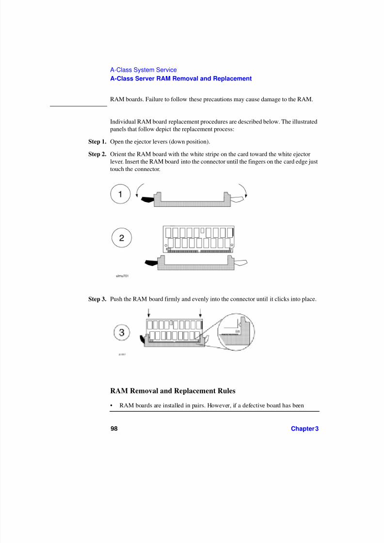
7/31/2019 A 180 Class Doc
http://slidepdf.com/reader/full/a-180-class-doc 98/122
98 Chapter 3
A-Class System Service
A-Class Server RAM Removal and Replacement
RAM boards. Failure to follow these precautions may cause damage to the RAM.
Individual RAM board replacement procedures are described below. The illustratedpanels that follow depict the replacement process:
Step 1. Open the ejector levers (down position).
Step 2. Orient the RAM board with the white stripe on the card toward the white ejectorlever. Insert the RAM board into the connector until the fingers on the card edge justtouch the connector.
Step 3. Push the RAM board firmly and evenly into the connector until it clicks into place.
RAM Removal and Replacement Rules
• RAM boards are installed in pairs. However, if a defective board has been

7/31/2019 A 180 Class Doc
http://slidepdf.com/reader/full/a-180-class-doc 99/122
Chapter 3 99
A-Class System Service
A-Class Server RAM Removal and Replacement
isolated, it may be replaced individually with a board of the same size. Forexample, a 128MB board must be replaced with another 128MB board.
• Memory is installed in the following increments:
128MB (two 64MB RAM boards)
256MB (two 128MB RAM boards)
512MB (two 256MB RAM boards).
• The smallest RAM pair must be installed in the lowest numbered slots, followedby the next larger pair in the next two slots until all slots are filled. Memory slotsare configured in the order shown below:
• If a memory pair is to be installed that is larger than the largest RAM pair of theexisting configuration: remove, reorder, and reinstall all pairs according to therules listed above.
0 BA
1 BA
2 BA
3 BA

7/31/2019 A 180 Class Doc
http://slidepdf.com/reader/full/a-180-class-doc 100/122
100 Chapter 3
A-Class System Service
A-Class Server Cache Memory Removal and Replacement
A-Class Server Cache Memory Removal and
Replacement
Overview
This section provides step-by-step instructions for removing and replacing CacheMemory boards in the A-Class Server. In addition, instructions are included forchanging product identification number labels if more Cache Memory is ordered forinstallation.The following subsections apply:
“Cache Memory Removal”
“Cache Memory Replacement”
“Cache Memory Labels”
CAUTION The procedures in this section require opening the server and exposing the system toelectrostatic discharge. Always observe all electrostatic precautions when workingwith components inside or out of the server. Failure to follow these precautions mayresult in component damage or loss of system reliability.
Electrostatic Discharge Precautions
• Use a grounding mat and an anti-static wrist strap.
• Wear the anti-static wrist strap to ensure that any accumulated electrostaticcharge is discharged from your body to ground.

7/31/2019 A 180 Class Doc
http://slidepdf.com/reader/full/a-180-class-doc 101/122
Chapter 3 101
A-Class System Service
A-Class Server Cache Memory Removal and Replacement
Before You Do Anything...
Step 1. Perform system backup.
Step 2. Shut down the operating system.
Step 3. Power down the system.
Step 4. Unplug the server.
NOTE Cabinet-mounted servers must be removed from the cabinet before proceeding.
Step 5. Remove the top of the server by unscrewing the knurled captive screws on each sideof the rear of the server. Slide the top back, lift it off, and set it aside.
Cache Memory Removal
CAUTION Always handle Cache Memory boards by their edges. Failure to comply with thisprecaution may result in damage to the board.
Step 1. Open the ejector levers (down position) on each side of the Cache Memory board.
MemoryCache

7/31/2019 A 180 Class Doc
http://slidepdf.com/reader/full/a-180-class-doc 102/122
102 Chapter 3
A-Class System Service
A-Class Server Cache Memory Removal and Replacement
Step 2. Grasp the Cache Memory by the edges and lift straight up
Step 3. Set it carefully on the grounding mat.
Cache Memory Replacement
CAUTION Keep Cache Memory boards in their protective anti-static bags until you are ready toinstall them. Always handle Cache Memory boards by their edges after you haveremoved them from their protective anti-static bags. Be sure that an anti-static wriststrap is still attached to your wrist and grounded to the server main chassis when youhandle and install Cache Memory boards. Failure to follow these precautions may
cause damage to the Cache Memory.
NOTE There is no order of precedence for installing Cache Memory boards. The twoboards may be installed in any order and do not have to be replaced in pairs if thedefective board can be isolated. Otherwise, replace the pair of boards.
NOTE A-Class servers can only use Cache Memory SIMMs with part numberA5182-60002. Using Cache Memory SIMMs with any other part number may resultin the server failing it’s selftest.
Cache Memory board replacement procedures are described as follows:
Step 1. Open the ejector levers (down position).
Step 2. Note the two key notches on the Cache Memory board. One key notch is in thecenter and one is toward the side. Orient the board so that the side key notch istoward the server front, matching the keys in the connector.
Step 3. Align the board notches with the connector keys, fit the bottom sides of the board

7/31/2019 A 180 Class Doc
http://slidepdf.com/reader/full/a-180-class-doc 103/122
Chapter 3 103
A-Class System Service
A-Class Server Cache Memory Removal and Replacement
into the ejector lever slots, and insert the board into the connector.
Step 4. Push the Cache memory board firmly and evenly into the connector until it clicksinto place. The ejector levers will automatically close.
Cache Memory Labels
If cache memory is ordered as an upgrade to the base product, two productidentification numbers must be changed. Locate the sheet that contains the newlabels and affix them according to the following procedure:
Key notches

7/31/2019 A 180 Class Doc
http://slidepdf.com/reader/full/a-180-class-doc 104/122
104 Chapter 3
A-Class System Service
A-Class Server Cache Memory Removal and Replacement
Step 1. Peel the Product number label from the sheet and place it over the correspondinglabel on the rear of the server.
Step 2. Peel the Model number label (includes the HP logo) from the sheet and place it overthe corresponding label on the rear of the server.

7/31/2019 A 180 Class Doc
http://slidepdf.com/reader/full/a-180-class-doc 105/122
Chapter 3 105
A-Class System Service
A-Class Server Disk Drive Removal and Replacement
A-Class Server Disk Drive Removal and Replacement
Overview
This section provides step-by-step instructions for removing and replacing the DiskDrive Bracket and Disk Drives in the A-Class Server. The following subsectionsapply:
“Remove the Bracket Containing the Disk Drive(s)”
“Remove the Disk Drive(s)”
“Disk Drive Replacement”
CAUTION The procedures in this section require opening the system cabinet and exposing thesystem to electrostatic discharge. Always observe all electrostatic precautions whenworking with components inside or out of the cabinet. Failure to follow theseprecautions may result in component damage or loss of system reliability.
Electrostatic Discharge Precautions
• Use a grounding mat and an anti-static wrist strap.
• Wear the anti-static wrist strap to ensure that any accumulated electrostaticcharge is discharged from your body to ground.
Before You Do Anything...
Step 1. Perform system backup.

7/31/2019 A 180 Class Doc
http://slidepdf.com/reader/full/a-180-class-doc 106/122
106 Chapter 3
A-Class System Service
A-Class Server Disk Drive Removal and Replacement
Step 2. Shut down the operating system.
Step 3. Power down the system.
Step 4. Unplug the server.
NOTE Cabinet-mounted servers must be removed from the cabinet before proceeding.
Step 5. Remove the top of the server by unscrewing the knurled captive screws on each sideof the rear of the server. Slide the top back, lift it off, and set it aside.
Disk Drive and Bracket Removal
Remove the Bracket Containing the Disk Drive(s)
Step 1. Remove the mounting screw that attaches the disk drive bracket to the bottom of the
chassis.Step 2. Slide the disk drive bracket (containing the disk drives) to the rear until it clears the
Disk
Drive(s)
a nd Bra cket

7/31/2019 A 180 Class Doc
http://slidepdf.com/reader/full/a-180-class-doc 107/122
Chapter 3 107
A-Class System Service
A-Class Server Disk Drive Removal and Replacement
anchor tabs, lift it out of the chassis, and place on a grounding mat.
Remove the Disk Drive(s)
Step 1. Disconnect disk drive cables. Observe the following for later reassembly:
a. Each disk drive power cable connector has rounded top corners that match thepower cable receptacle to ensure that the connection is made correctly.Each diskdrive ribbon cable connector has a key centered on top that fits into a slot on thedata cable receptacle to ensure that the connection is made correctly.
b. Note the disk drive jumper settings on the front of the drive that you are
removing in order to reset the replacement drive to the same jumperconfiguration.

7/31/2019 A 180 Class Doc
http://slidepdf.com/reader/full/a-180-class-doc 108/122
108 Chapter 3
A-Class System Service
A-Class Server Disk Drive Removal and Replacement
Step 2. Remove the screws from the bracket on both sides of the defective disk drive.
a. If the defective disk drive is on top, either slide the unit out of the bracket or liftit straight up.
b. If the defective disk drive is on the bottom, slide the unit out of either end of thebracket.

7/31/2019 A 180 Class Doc
http://slidepdf.com/reader/full/a-180-class-doc 109/122
Chapter 3 109
A-Class System Service
A-Class Server Disk Drive Removal and Replacement
Disk Drive Replacement
CAUTION DO NOT install a single disk drive on the top rails of the bracket. Always install asingle disk drive on the bottom rails. Failure to follow this precaution may causedamage due to excessive vibration.
When reinstalling disk drives, ensure that the SCSI IDs are set correctly.
The following illustration shows typical setting of the disk drive ID.
NOTE This illustration of ID jumper settings is typical. Your drive may be different.
Consult the literature and labels on your drive for ID setting instructions.
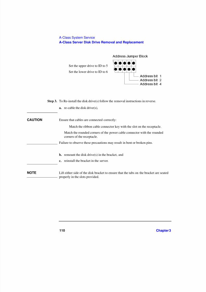
7/31/2019 A 180 Class Doc
http://slidepdf.com/reader/full/a-180-class-doc 110/122
110 Chapter 3
A-Class System Service
A-Class Server Disk Drive Removal and Replacement
Step 3. To Re-install the disk drive(s) follow the removal instructions in reverse.a. re-cable the disk drive(s),
CAUTION Ensure that cables are connected correctly:
Match the ribbon cable connector key with the slot on the receptacle.
Match the rounded corners of the power cable connector with the roundedcorners of the receptacle.
Failure to observe these precautions may result in bent or broken pins.
b. remount the disk drive(s) in the bracket, and
c. reinstall the bracket in the server.
NOTE Lift either side of the disk bracket to ensure that the tabs on the bracket are seatedproperly in the slots provided.
Set the upper drive to ID to 5
Set the lower drive to ID to 6

7/31/2019 A 180 Class Doc
http://slidepdf.com/reader/full/a-180-class-doc 111/122
Chapter 3 111
A-Class System Service
A-Class Server I/O Card Removal and Replacement
A-Class Server I/O Card Removal and Replacement
Introduction
This section provides card load order rules and step-by-step instructions forremoving and replacing I/O cards in the A-Class Server. The following subsectionsapply:
“Card Load Order Rules”
“I/O Card Removal”
“I/O Card Replacement”
CAUTION The procedures in this section require opening the system cabinet and exposing thesystem to electrostatic discharge. Always observe all electrostatic precautions whenworking with components inside or out of the cabinet. Failure to follow theseprecautions may result in component damage or loss of system reliability.
Electrostatic Discharge Precautions
• Use a grounding mat and an anti-static wrist strap.
• Wear the anti-static wrist strap to ensure that any accumulated electrostaticcharge is discharged from your body to ground.
Before You Do Anything...
Step 1. Perform system backup.

7/31/2019 A 180 Class Doc
http://slidepdf.com/reader/full/a-180-class-doc 112/122
112 Chapter 3
A-Class System Service
A-Class Server I/O Card Removal and Replacement
Step 2. Shut down the operating system.
Step 3. Power down the system.
Step 4. Unplug the server.
NOTE Cabinet-mounted servers must be removed from the cabinet before proceeding.
Step 5. Remove the top of the server by unscrewing the knurled captive screws on each sideof the rear of the server. Slide the top back, lift it off, and set it aside.
Card Load Order Rules
Card Rule
Access Port (AP) card Must go in the bottom slot.
One HSC card and one PCI card HSC card must go in the bottom slot
All PCI or all HSC cards Load order doesn’t matter.
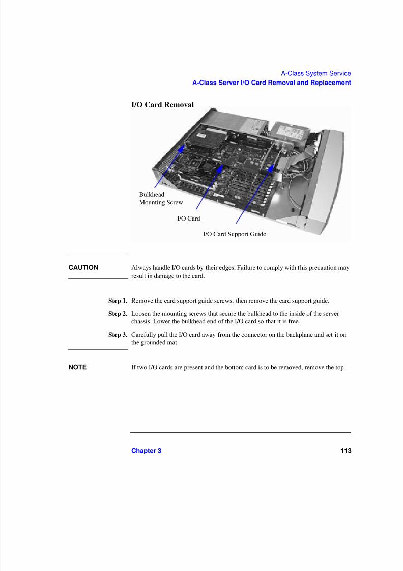
7/31/2019 A 180 Class Doc
http://slidepdf.com/reader/full/a-180-class-doc 113/122
Chapter 3 113
A-Class System Service
A-Class Server I/O Card Removal and Replacement
I/O Card Removal
CAUTION Always handle I/O cards by their edges. Failure to comply with this precaution mayresult in damage to the card.
Step 1. Remove the card support guide screws, then remove the card support guide.
Step 2. Loosen the mounting screws that secure the bulkhead to the inside of the serverchassis. Lower the bulkhead end of the I/O card so that it is free.
Step 3. Carefully pull the I/O card away from the connector on the backplane and set it onthe grounded mat.
NOTE If two I/O cards are present and the bottom card is to be removed, remove the top
Bulkhead
Mounting Screw
I/O Card
I/O Card Support Guide

7/31/2019 A 180 Class Doc
http://slidepdf.com/reader/full/a-180-class-doc 114/122
114 Chapter 3
A-Class System Service
A-Class Server I/O Card Removal and Replacement
card first.
I/O Card Replacement
CAUTION Keep I/O cards in their protective anti-static bags until you are ready to install them.Always handle I/O cards by their edges after you have removed them from their
protective anti-static bags. Be sure that an anti-static wrist strap is still attached toyour wrist and grounded to the cabinet main chassis when you handle and install theI/O card. Failure to follow these precautions may cause damage to the I/O card.
I/O card replacement procedures are described as follows:
Step 1. Carefully insert the I/O card into the backplane connector. The tab on the bulkheadwill slide into its slot in the chassis.
Step 2. Attach the card support guide to the front edge of the I/O card, hook the tab into itsslot, and secure the support guide with the mounting screw.
Step 3. Slide the bulkhead slotted tab up into position between the captive screw and
chassis, and tighten the captive screw.

7/31/2019 A 180 Class Doc
http://slidepdf.com/reader/full/a-180-class-doc 115/122
Chapter 3 115
A-Class System Service
Replacing an A-Class Server Exchange Base Unit (EBU)
Replacing an A-Class Server Exchange Base Unit (EBU)
Overview
When troubleshooting a defective A-Class server has determined that the fault liesin a portion of the server that cannot be replaced at the site, field-replaceablecomponents must be removed prior to exchanging the defective server for anoperational unit. This “stripped-down” server is the EBU.
The following subsections apply:
“Removable Components”
“Move the Components to the EBU”
“Apply New Labels”“Labels Applicable to the A5183A (A180C) EBU”
“Reinstall the System”
“Restart the System”
Ensure that you obtain required Web Console configuration data (user names andpasswords, IP address, etc.) prior to replacing the EBU.
NOTE Web Console user login information and passwords are not retained by, and cannotbe acquired by, the Web Console. This information is kept by the Web ConsoleAdministrator or System Manager.
The following configuration information can be obtained from the Web ConsoleMain Menu:

7/31/2019 A 180 Class Doc
http://slidepdf.com/reader/full/a-180-class-doc 116/122
116 Chapter 3
A-Class System Service
Replacing an A-Class Server Exchange Base Unit (EBU)
• IP Configuration:
o Secure Console Name
o IP Address
o IP Subnet Mask
o IP Gateway
o System Name.
• Datacomm Configuration:
o Baud Rate
o Parity/Data Bitso Parity Checking
o Recvpace/Xmitpace.
When the new EBU has been received, place the original system and the new EBUside-by-side on an ESD-protected work area. Now you can remove the FRUs fromthe original system and install them directly into the new EBU.
CAUTION The procedures in this section require opening the system cabinet and exposing thesystem to electrostatic discharge. Always observe all electrostatic precautions whenworking with components inside or out of the cabinet. Failure to follow these
precautions may result in component damage or loss of system reliability.
Electrostatic Discharge Precautions
• Use a grounding mat and an anti-static wrist strap.
• Wear the anti-static wrist strap to ensure that any accumulated electrostaticcharge is discharged from your body to ground.
Before You Do Anything...
Step 1. Perform system backup.Step 2. Shut down the operating system.
Step 3. Power down the system.

7/31/2019 A 180 Class Doc
http://slidepdf.com/reader/full/a-180-class-doc 117/122
Chapter 3 117
A-Class System Service
Replacing an A-Class Server Exchange Base Unit (EBU)
Step 4. Unplug the server.
NOTE Cabinet-mounted servers must be removed from the cabinet before proceeding.
Step 5. Remove the top of the server by unscrewing the knurled captive screws on each sideof the rear of the server. Slide the top back, lift it off, and set it aside.
Removable Components
The components listed below must be removed from the defective server prior toexchanging it for an operational unit. Click on each name to link to theremove/replace instructions for that item.
“A-Class Server RAM Removal and Replacement”
“A-Class Server Cache Memory Removal and Replacement”
“A-Class Server Disk Drive Removal and Replacement”
NOTE Do not remove disk drives from the bracket.
“A-Class Server I/O Card Removal and Replacement”
NOTE As you remove the memory and I/O cards from the original system, note the slotsfrom which they came. They must be installed in the same slots in the EBU toensure that the system operates properly.
If you don’t know the order in which the I/O cards were removed, refer to a recentioscan (or other mapping utility) output. The information shown below can be usedto match a path with an I/O card slot:
HSC Cards PCI Cards
Path Slot Path Slot
8/4.x Slot 1 8/0/1.x Slot 1

7/31/2019 A 180 Class Doc
http://slidepdf.com/reader/full/a-180-class-doc 118/122
118 Chapter 3
A-Class System Service
Replacing an A-Class Server Exchange Base Unit (EBU)
Slot 1 is the TOP slot and slot 2 is the BOTTOM slot, when looking at the serverfrom the rear. The “x” is an operator-input variable.
If you don’t know the order of memory card removal, refer to the Memory LoadingRules on the label located under the server lid, attached to the top.
Move the Components to the EBU
The following paragraphs discuss how to transfer the components from the server tothe EBU.
Unpack the EBU
When the new EBU is received, follow the directions in the A-Class Server
Unpacking Instructions section.
NOTE The contents in the new EBU carton may vary from those listed in the unpackinginstructions section.
Install the Components in the EBU
After the new EBU has been unpacked, replace the components according to theinstructions for each item listed in the Removable Components subsection.
Apply New Labels
Each new EBU is shipped with the following labels:
• A5182-84002: Plastic label with A5183A, A1880C, and HP logo markings.
• A5182-84004: Bar coded label with A5183A markings.
• A5182-84005: Three blank stickers.
After you have switched the original system FRUs to the new EBU, locate and applythe labels listed above to the corresponding area on the rear of the new EBU.
8/8.x Slot 2 8/0/2.x Slot 2
HSC Cards PCI Cards
Path Slot Path Slot

7/31/2019 A 180 Class Doc
http://slidepdf.com/reader/full/a-180-class-doc 119/122
Chapter 3 119
A-Class System Service
Replacing an A-Class Server Exchange Base Unit (EBU)
Labels Applicable To All Models First, copy the serial number, located on theserver’s rear label, from the original system to one of the blank stickers. The serialnumber is a 10 character number beginning with three alpha characters followed byseven numeric characters. For example:
USJ0009837
Place the new sticker with the original system serial number in the field marked“Serial Number” on the new EBU.
NOTE Serial numbers are used to verify Warranty and Hardware Support levels. ALWAYStransfer the serial number of the original system to the new EBU.
Next, copy the LAN station address, located on the server’s rear label, from theoriginal system to one of the blank stickers. The LAN station address consists of 12alphanumeric characters.
NOTE DO NOT enter the “Web Console MAC Address” value, located just above the LANstation address. Enter the “LAN Station Address” value ONLY.
Place the new sticker with the original LAN station address in the field marked“LAN Station Address” on the new EBU.
The third blank sticker is an extra.
Labels Applicable to the A5183A (A180C) EBU
Locate the plastic sticker that contains the numbers, A5183A and A180C, andincludes the HP logo. Paste it over the original label on the rear of the new EBU.The difference between labels is the modification of the model number from A180to A180C.
Locate the new bar coded sticker with A5183 markings and place it on the rear label

7/31/2019 A 180 Class Doc
http://slidepdf.com/reader/full/a-180-class-doc 120/122
120 Chapter 3
A-Class System Service
Replacing an A-Class Server Exchange Base Unit (EBU)
of the new EBU in the field marked, “Product Number” (over the A5182 text).
Reinstall the System
If the replacement A-Class server is used as a single independent unit, refer toChapter 2, Stand-Alone A-Class Server Unpack and Install instructions.
If the replacement server is to be re-installed in an HP-approved cabinet, refer toChapter 2, Cabinet-Mounted A-Class Server System Unpack and Install instructions.
When the basic reinstallation procedures are complete, refer to Chapter 2instructions to reconnect the replacement server to external devices and power. This
information is also found in the Cabinet-Mounted A-Class Server System Unpack and Install instructions.

7/31/2019 A 180 Class Doc
http://slidepdf.com/reader/full/a-180-class-doc 121/122
Chapter 3 121
A-Class System Service
Replacing an A-Class Server Exchange Base Unit (EBU)
Restart the System
Refer to Chapter 2 for applying power to and initiating selftest on both the serverand other external devices, and booting the system.
The integrated A-Class Web Console will require reconfiguring. Follow theinstructions in Chapter 2, A-Class Server Power Up and Boot Procedures tocomplete this task.
When the replacement server is powered up and selftest has successfully completed,you will be prompted to enter the LAN Station Address. This is a one-time promptthat only occurs during the initial system configuration.
The terminal will display: WARNING: The system LAN Station Addresshas not been set.
The System LAN Station Address is not set.
WARNING: The LAN Station Address can be set one time only.
Set now [Y/N]?
Type Y and press Enter. The “LAN Station Address” value is locatedon the rear of the system.
Do not enter the value for the “Web Console MAC Address”.
NOTE As it appears on the rear label, the LAN Station Address does not include a hyphen(-). However, a hyphen is required (for example: xxxxxx-xxxxxx) when entering theLAN Station Address at this prompt.
This action cannot be undone.
Confirm LAN Station address 0060b0-83c41b [Y/N/Q(uit)]? Type Y and press Enter.
The terminal will display: The system has been initialized with LANStation Address 0060b0-83c41b.
NOTE The system will reset itself, re-run selftest, and perform a normal power-on selftest.
The replacement server is now ready to continue normal boot and power-upprocedures.
7/31/2019 A 180 Class Doc
http://slidepdf.com/reader/full/a-180-class-doc 122/122
A-Class System Service
Replacing an A-Class Server Exchange Base Unit (EBU)


![Korean Class 101 - Beginner 1 [180]](https://img.pdfslide.us/doc/110x75/553345044a7959824c8b48a4/korean-class-101-beginner-1-180.jpg)