Embed Size (px)
Citation preview
March 2007
A-110
For more information visit: www.EatonElectrical.ca CA08102001K
NEMA Contactors & Starters
A
AdvantageProduct Family Overview
Size 1 and 2 Starter
Product DescriptionSetting the Standard in Motor ControlCutler-Hammer® Advantage motor starters from Eaton’s electrical busi-ness have extended operating life in a physical space requirement one half the size of conventional motor starters.
Offering motor overcurrent protection accurate to 2% at maximum FLC, Advantage also maintains constant coil power regardless of varying con-trol circuit conditions, eliminating coil burnout, contact chatter and welding due to low voltage of fluttering control signals.
Advantage is designed with a full com-plement of features that make it the most versatile motor starter in the industry. Multifunction overload pro-tection options provide application flexibility while reducing inventory. Communication capability extends benefits, allowing Advantage to be interactively linked to higher order control systems for monitoring, troubleshooting and control.
Technological advances incorporated in the Advantage design, such as pre-start diagnostics, increased accuracy and the ability to communicate with other systems, are benefits not real-ized in traditional motor starters.
BenefitsAdvantage BreakthroughsTo achieve the level of benefits envi-sioned for Advantage controls at a competitive price, it was discovered early in the development process that simply improving existing design con-cepts would fall short of the mark. A new approach involving a higher level of technology was required. The result was the incorporation of three techni-cal breakthroughs — new current
sensing monitoring, an energy-balanced contact closure system that increased life by decreasing electrical and mechanical wear and an intelli-gent coil controller optimizing the con-tact closing process based on varying control circuit conditions. Coordinat-ing these breakthroughs to provide enhanced motor control performance is concentrated in the SURE chip.
Advantage uses the right combination of brains and brawn in effecting a motor start. The power circuit of the contactor employs heavy-duty silver alloy contacts scientifically designed for long life. The addition of a uniquely developed application-specific micro-processor chip regulates power sup-plied to the operating coil. The regulated closing profile is tailored to existing control circuit conditions. This results in an energy balanced system which reduces armature/magnet crash and contact bounce, extending mechanical and electrical life.
Improved Protection and Motor UtilizationThe motor circuit monitoring and over-load protection functions of Advan-tage starters are provided by three current sensors closely monitored by the microprocessor. This sensor/microprocessor combination yields a protection scheme closely paralleling
that of the motor heating damage boundary expressed in terms of cur-rent and time. Accurate to 2% of full scale, Advantage allows full utilization of motor capability without motor damage or nuisance tripping.
No Heaters, Small SizeAdvantage starters eliminate the need for costly heater elements and their associated installation expense. Standard overload protection func-tions include phase loss and unbal-ance protection, selectable trip class, automatic/manual reset and ground current protection.
Built-In Communications Capabilities Provide Two-Way ControlAdvantage also offers low cost commu-nication capability. ON/OFF commands, status and motor data can be linked to automated control systems without the addition of costly sensors, I/O modules and transducers, in a language compat-ible with many computer-based soft-ware systems in use today.
Protected by 22 patents and proven in many years of operating experience in harsh industrial applications, Advan-tage motor starters and contactors offer the user unprecedented value at a price competitive with traditional devices.
Instructional Leaflets17401 Sizes 1, 2 Non-reversing Contactors and Starters17403 Sizes 3, 4 Non-reversing Contactors and Starters17405 Sizes 5, 6 Non-reversing Contactors and Starters17482 Sizes 1, 2 Reversing Contactors and Starters17484B Sizes 3, 4 Reversing Contactors and Starters17486 Sizes 5, 6 Reversing Contactors and Starters17456 Sizes 1, 2 Contactor Overload Combo17457 Sizes 3, 4 Contactor Overload Combo17604 Sizes 5, 6 Contactor Overload Combo17595 Sizes 1, 2 Reversing Contactors and Starters with status-only ACM17596 Sizes 3, 4 Reversing Contactors and Starters with status-only ACM17597 Sizes 5, 6 Reversing Contactors and Starters with status-only ACM17598 Sizes 1, 2 Two-Speed Two-Winding Starters with status-only ACM17599 Sizes 3, 4 Two-Speed Two-Winding Starters with status-only ACM17600 Sizes 5, 6 Two-Speed Two-Winding Starters with status-only ACM17601 Sizes 1, 2 Two-Speed One-Winding Starters with status-only ACM17602 Sizes 3, 4 Two-Speed One-Winding Starters with status-only ACM17603 Sizes 5, 6 Two-Speed One-Winding Starters with status-only ACM
Tab33.book Page 110 Thursday, February 22, 2007 10:27 AM
March 2007
CA08102001K For more information visit: www.EatonElectrical.ca
A-111NEMA Contactors & Starters
A
AdvantageContactors — Non-reversing and Reversing
ContentsDescription Page
Product Family Overview
Product Description . . . . . . A-110
Benefits . . . . . . . . . . . . . . . . A-110
Contactors — Non-reversing and Reversing
Product Description . . . . . . A-111
Features . . . . . . . . . . . . . . . A-111
Product Selection. . . . . . . . A-111
Technical Data . . . . . . . . . . . . . A-116
Accessories and FieldModification Kits . . . . . . . . . A-121
Renewal Parts . . . . . . . . . . . . A-123
Control Modules . . . . . . . . . . . A-124
Dimensions . . . . . . . . . . . . . . . A-126
Wiring Diagrams . . . . . . . . . . . A-132
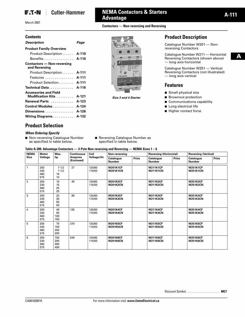
Size 3 and 4 Starter
Product DescriptionCatalogue Number W201 — Non-reversing Contactors
Catalogue Number W211 — Horizontal Reversing Contactors (shown above) — long axis horizontal
Catalogue Number W251 — Vertical Reversing Contactors (not illustrated) — long axis vertical
Features� Small physical size� Brownout protection� Communications capability� Long electrical life� Higher contact force
Product Selection When Ordering Specify � Non-reversing Catalogue Number
as specified in table below.� Reversing Catalogue Number as
specified in table below.
Table A-209. Advantage Contactors — 3-Pole Non-reversing and Reversing — NEMA Sizes 1 – 6 NEMASize
MotorVoltage
Max.hp
ContinuousAmperes(Enclosed)
Coil Voltage/Hz
Non-reversing Reversing (Horizontal) Reversing (Vertical)
CatalogueNumber
Price CatalogueNumber
Price CatalogueNumber
Price
1 200230460575
7-1/27-1/2
1010
27 120/60110/50
W201K1CFW201K1CN
W211K1CFW211K1CN
W251K1CFW251K1CN
2 200230460575
10152525
45 120/60110/50
W201K2CFW201K2CN
W211K2CFW211K2CN
W251K2CFW251K2CN
3 200230460575
25305050
90 120/60110/50
W201K3CFW201K3CN
W211K3CFW211K3CN
W251K3CFW251K3CN
4 200230460575
4050
100100
135 120/60110/50
W201K4CFW201K4CN
W211K4CFW211K4CN
W251K4CFW251K4CN
5 200230460575
75100200200
270 120/60110/50
W201K5CFW201K5CN
W211K5CFW211K5CN
W251K5CFW251K5CN
6 200230460575
150200400400
540 120/60110/50
W201K6CFW201K6CN
W211K6CFW211K6CN
W251K6CFW251K6CN
Discount Symbol . . . . . . . . . . . . . . . . . . . . . . . . . MC7
Tab33.book Page 111 Thursday, February 22, 2007 10:27 AM
March 2007
A-112
For more information visit: www.EatonElectrical.ca CA08102001K
NEMA Contactors & Starters
A
AdvantageStarters — Non-reversing and Reversing
ContentsDescription Page
Product Family Overview
Product Description. . . . . . . A-110
Benefits. . . . . . . . . . . . . . . . . A-110
Starters — Non-reversing and Reversing
Product Description. . . . . . . A-112
Features . . . . . . . . . . . . . . . . A-112
Technical Data . . . . . . . . . . . A-112
Options . . . . . . . . . . . . . . . . . A-112
Product Selection . . . . . . . . A-113
Technical Data. . . . . . . . . . . . . . A-116
Accessories and FieldModification Kits . . . . . . . . . . A-121
Renewal Parts . . . . . . . . . . . . . A-123
Control Modules . . . . . . . . . . . . A-124
Dimensions . . . . . . . . . . . . . . . . A-126
Wiring Diagrams. . . . . . . . . . . . A-133
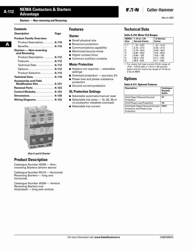
Size 5 and 6 Starter
Product DescriptionCatalogue Number W200 — Non-reversing Starters (shown above)
Catalogue Number W210 — Horizontal Reversing Starters — long axis horizontal.
Catalogue Number W250 — Vertical Reversing Starters (not illustrated) — long axis vertical.
Features
Starter� Small physical size� Brownout protection� Communications capability� Minimized bounce times� Higher contact force� Common auxiliary contacts
Motor Protection� Heaters not required — selectable
settings� Overload protection — accuracy 2%� Phase loss and phase unbalance
protection� Ground current protection
OL Protection Settings� Selectable automatic/manual reset� Selectable trip class — 10, 20, 30 or
no protection (disables overload)� Selectable trip current
Technical DataTable A-210. Motor FLA Ranges
� For motor full load current (FLA) range of .47A – 3.81A with a 1.15 to 1.25 service factor and for motor hp range of 1/4 hp to 2 hp at 460V.
OptionsTable A-211. Optional Features
NEMASize
1.15 to 1.25Service Factor
1.0 Service Factor
1 �123456
.47 – 3.813.15 – 27.03.15 – 45.09.90 – 90.09.90 – 13538.3 – 27038.3 – 540
.51 – 4.143.43 – 27.03.43 – 45.010.8 – 90.010.8 – 13541.7 – 27041.7 – 540
Description CatalogueNumberSuffix
Omit Class II Ground-Current Protection
Y7
Omit Phase-Loss Protection Y4
Omit both Class II Ground-Current Protection and Phase-Loss Protection
Y4Y7
Tab33.book Page 112 Thursday, February 22, 2007 10:27 AM
March 2007
CA08102001K For more information visit: www.EatonElectrical.ca
A-113NEMA Contactors & Starters
A
AdvantageStarters — Non-reversing and Reversing
Product SelectionWhen Ordering Specify � Non-reversing Catalogue Number
as specified in table below.� Reversing Catalogue Number as
specified in table below.
Table A-212. Advantage Starters — 3-Pole Non-reversing and Reversing — Wired for Separate Control — Heaters Not Required — NEMA Sizes 1 – 6
� For motor full load current (FLA) range of .47A – 3.81A with a 1.15 to 1.25 service factor and for motor hp range of 1/4 hp to 2 hp at 460V.
NEMASize
MotorVoltage
Max.hp
ContinuousAmperes(Enclosed)
Coil Voltage/Hz
Non-reversing Reversing (Horizontal) Reversing (Vertical)
CatalogueNumber
Price CatalogueNumber
Price CatalogueNumber
Price
1 � 200230460575
1122
27 120/60110/50
W200MLCFCW200MLCNC
W210MLCFCW210MLCNC
W250MLCFCW250MLCNC
1 200230460575
7-1/27-1/2
1010
27 120/60110/50
W200M1CFCW200M1CNC
W210M1CFCW210M1CNC
W250M1CFCW250M1CNC
2 200230460575
10152525
45 120/60110/50
W200M2CFCW200M2CNC
W210M2CFCW210M2CNC
W250M2CFCW250M2CNC
3 200230460575
25305050
90 120/60110/50
W200M3CFCW200M3CNC
W210M3CFCW210M3CNC
W250M3CFCW250M3CNC
4 200230460575
4050
100100
135 120/60110/50
W200M4CFCW200M4CNC
W210M4CFCW210M4CNC
W250M4CFCW250M4CNC
5 200230460575
75100200200
270 120/60110/50
W200M5CFCW200M5CNC
W210M5CFCW210M5CNC
W250M5CFCW250M5CNC
6 200230460575
150200400400
540 120/60110/50
W200M6CFCW200M6CNC
W210M6CFCW210M6CNC
W250M6CFCW250M6CNC
Discount Symbol . . . . . . . . . . . . . . . . . . . . . . . . . MC7
Tab33.book Page 113 Thursday, February 22, 2007 10:27 AM
March 2007
A-114
For more information visit: www.EatonElectrical.ca CA08102001K
NEMA Contactors & Starters
A
AdvantageStarters — Non-reversing, Two-Speed
ContentsDescription Page
Product Family Overview
Product Description. . . . . . . A-110
Benefits. . . . . . . . . . . . . . . . . A-110
Starters — Non-reversingTwo-Speed
Product Selection . . . . . . . . A-114
Technical Data. . . . . . . . . . . . . . A-116
Accessories and FieldModification Kits . . . . . . . . . . A-121
Renewal Parts . . . . . . . . . . . . . A-123
Control Modules . . . . . . . . . . . . A-124
Dimensions . . . . . . . . . . . . . . . . A-126
Product SelectionWhen Ordering Specify� Catalogue Number as shown in
table below.
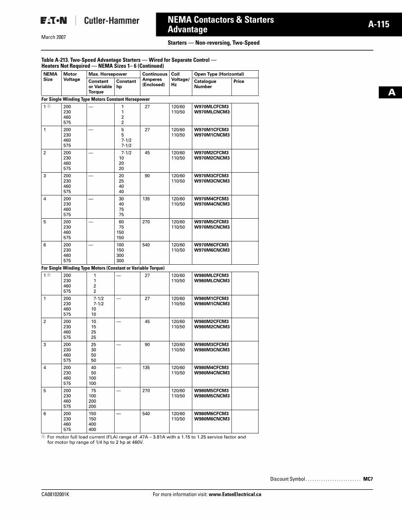
Table A-213. Two-Speed Advantage Starters — Wired for Separate Control — Heaters Not Required — NEMA Sizes 1 – 6
� For motor full load current (FLA) range of .47A – 3.81A with a 1.15 to 1.25 service factor and for motor hp range of 1/4 hp to 2 hp at 460V.
NEMA Size
MotorVoltage
Max. Horsepower ContinuousAmperes(Enclosed)
CoilVoltage/Hz
Open Type (Horizontal)
Constantor VariableTorque
Constanthp
CatalogueNumber
Price
For Separate (2) Winding Type Motors — Wye Wye1 � 200
230460575
1122
1122
27 120/60110/50
W960MLCFCM3W960MLCNCM3
1 200230460575
7-1/27-1/2
1010
557-1/27-1/2
27 120/60110/50
W960M1CFCM3W960M1CNCM3
2 200230460575
10152525
7-1/2102020
45 120/60110/50
W960M2CFCM3W960M2CNCM3
3 200230460575
25305050
20254040
90 120/60110/50
W960M3CFCM3W960M3CNCM3
4 200230460575
4050
100100
30407575
135 120/60110/50
W960M4CFCM3W960M4CNCM3
5 200230460575
75100200200
6075
150150
270 120/60110/50
W960M5CFCM3W960M5CNCM3
6 200230460575
150200400400
100150300300
540 120/60110/50
W960M6CFCM3W960M6CNCM3
Discount Symbol . . . . . . . . . . . . . . . . . . . . . . . . . MC7
Tab33.book Page 114 Thursday, February 22, 2007 10:27 AM
CA08102001K For more information visit: www.EatonElectrical.ca
A-115NEMA Contactors & Starters
March 2007
A
AdvantageStarters — Non-reversing, Two-Speed
Table A-213. Two-Speed Advantage Starters — Wired for Separate Control — Heaters Not Required — NEMA Sizes 1– 6 (Continued)
� For motor full load current (FLA) range of .47A – 3.81A with a 1.15 to 1.25 service factor and for motor hp range of 1/4 hp to 2 hp at 460V.
NEMA Size
MotorVoltage
Max. Horsepower ContinuousAmperes(Enclosed)
CoilVoltage/Hz
Open Type (Horizontal)
Constantor VariableTorque
Constanthp
CatalogueNumber
Price
For Single Winding Type Motors Constant Horsepower 1 � 200
230460575
— 1122
27 120/60110/50
W970MLCFCM3W970MLCNCM3
1 200230460575
— 557-1/27-1/2
27 120/60110/50
W970M1CFCM3W970M1CNCM3
2 200230460575
— 7-1/2102020
45 120/60110/50
W970M2CFCM3W970M2CNCM3
3 200230460575
— 20254040
90 120/60110/50
W970M3CFCM3W970M3CNCM3
4 200230460575
— 30407575
135 120/60110/50
W970M4CFCM3W970M4CNCM3
5 200230460575
— 6075
150150
270 120/60110/50
W970M5CFCM3W970M5CNCM3
6 200230460575
— 100150300300
540 120/60110/50
W970M6CFCM3W970M6CNCM3
For Single Winding Type Motors (Constant or Variable Torque)1 � 200
230460575
1122
— 27 120/60110/50
W980MLCFCM3W980MLCNCM3
1 200230460575
7-1/27-1/2
1010
— 27 120/60110/50
W980M1CFCM3W980M1CNCM3
2 200230460575
10152525
— 45 120/60110/50
W980M2CFCM3W980M2CNCM3
3 200230460575
25305050
— 90 120/60110/50
W980M3CFCM3W980M3CNCM3
4 200230460575
4050
100100
— 135 120/60110/50
W980M4CFCM3W980M4CNCM3
5 200230460575
75100200200
— 270 120/60110/50
W980M5CFCM3W980M5CNCM3
6 200230460575
150150400400
— 540 120/60110/50
W980M6CFCM3W980M6CNCM3
Discount Symbol . . . . . . . . . . . . . . . . . . . . . . . . . MC7
Tab33.book Page 115 Thursday, February 22, 2007 10:27 AM
March 2007
A-116
For more information visit: www.EatonElectrical.ca CA08102001K
NEMA Contactors & Starters
A
AdvantageTechnical Data and Specifications
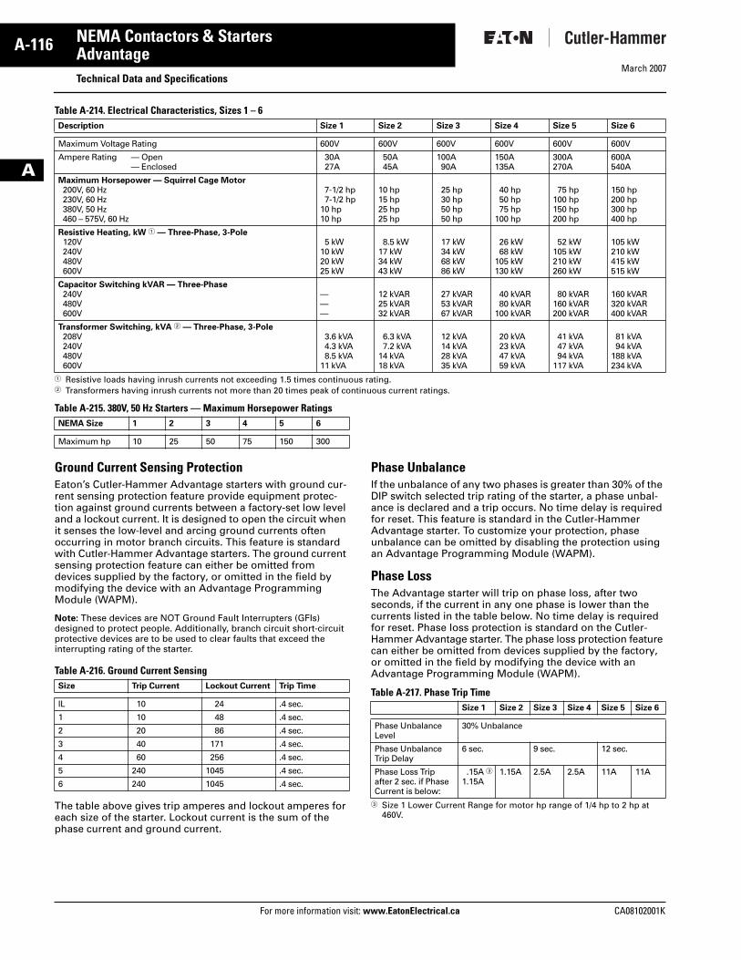
Table A-214. Electrical Characteristics, Sizes 1 – 6
� Resistive loads having inrush currents not exceeding 1.5 times continuous rating.� Transformers having inrush currents not more than 20 times peak of continuous current ratings.
Table A-215. 380V, 50 Hz Starters — Maximum Horsepower Ratings
Ground Current Sensing ProtectionEaton’s Cutler-Hammer Advantage starters with ground cur-rent sensing protection feature provide equipment protec-tion against ground currents between a factory-set low level and a lockout current. It is designed to open the circuit when it senses the low-level and arcing ground currents often occurring in motor branch circuits. This feature is standard with Cutler-Hammer Advantage starters. The ground current sensing protection feature can either be omitted from devices supplied by the factory, or omitted in the field by modifying the device with an Advantage Programming Module (WAPM).
Note: These devices are NOT Ground Fault Interrupters (GFIs) designed to protect people. Additionally, branch circuit short-circuit protective devices are to be used to clear faults that exceed the interrupting rating of the starter.
Table A-216. Ground Current Sensing
The table above gives trip amperes and lockout amperes for each size of the starter. Lockout current is the sum of the phase current and ground current.
Phase UnbalanceIf the unbalance of any two phases is greater than 30% of the DIP switch selected trip rating of the starter, a phase unbal-ance is declared and a trip occurs. No time delay is required for reset. This feature is standard in the Cutler-Hammer Advantage starter. To customize your protection, phase unbalance can be omitted by disabling the protection using an Advantage Programming Module (WAPM).
Phase LossThe Advantage starter will trip on phase loss, after two seconds, if the current in any one phase is lower than the currents listed in the table below. No time delay is required for reset. Phase loss protection is standard on the Cutler-Hammer Advantage starter. The phase loss protection feature can either be omitted from devices supplied by the factory, or omitted in the field by modifying the device with an Advantage Programming Module (WAPM).
Table A-217. Phase Trip Time
� Size 1 Lower Current Range for motor hp range of 1/4 hp to 2 hp at 460V.
Description Size 1 Size 2 Size 3 Size 4 Size 5 Size 6
Maximum Voltage Rating 600V 600V 600V 600V 600V 600V
Ampere Rating — Open— Enclosed
30A27A
50A45A
100A90A
150A135A
300A270A
600A540A
Maximum Horsepower — Squirrel Cage Motor200V, 60 Hz230V, 60 Hz380V, 50 Hz460 – 575V, 60 Hz
7-1/2 hp7-1/2 hp
10 hp10 hp
10 hp15 hp25 hp25 hp
25 hp30 hp50 hp50 hp
40 hp50 hp75 hp
100 hp
75 hp100 hp150 hp200 hp
150 hp200 hp300 hp400 hp
Resistive Heating, kW � — Three-Phase, 3-Pole120V240V480V600V
5 kW10 kW20 kW25 kW
8.5 kW17 kW34 kW43 kW
17 kW34 kW68 kW86 kW
26 kW68 kW
105 kW130 kW
52 kW105 kW210 kW260 kW
105 kW210 kW415 kW515 kW
Capacitor Switching kVAR — Three-Phase240V480V600V
———
12 kVAR25 kVAR32 kVAR
27 kVAR53 kVAR67 kVAR
40 kVAR80 kVAR
100 kVAR
80 kVAR160 kVAR200 kVAR
160 kVAR320 kVAR400 kVAR
Transformer Switching, kVA � — Three-Phase, 3-Pole208V240V480V600V
3.6 kVA4.3 kVA8.5 kVA
11 kVA
6.3 kVA7.2 kVA
14 kVA18 kVA
12 kVA14 kVA28 kVA35 kVA
20 kVA23 kVA47 kVA59 kVA
41 kVA47 kVA94 kVA
117 kVA
81 kVA94 kVA
188 kVA234 kVA
NEMA Size 1 2 3 4 5 6
Maximum hp 10 25 50 75 150 300
Size Trip Current Lockout Current Trip Time
IL 10 24 .4 sec.
1 10 48 .4 sec.
2 20 86 .4 sec.
3 40 171 .4 sec.
4 60 256 .4 sec.
5 240 1045 .4 sec.
6 240 1045 .4 sec.
Size 1 Size 2 Size 3 Size 4 Size 5 Size 6
Phase Unbalance Level
30% Unbalance
Phase Unbalance Trip Delay
6 sec. 9 sec. 12 sec.
Phase Loss Trip after 2 sec. if Phase Current is below:
.15A �1.15A
1.15A 2.5A 2.5A 11A 11A
Tab33.book Page 116 Thursday, February 22, 2007 10:27 AM
March 2007
CA08102001K For more information visit: www.EatonElectrical.ca
A-117NEMA Contactors & Starters
A
AdvantageTechnical Data and Specifications
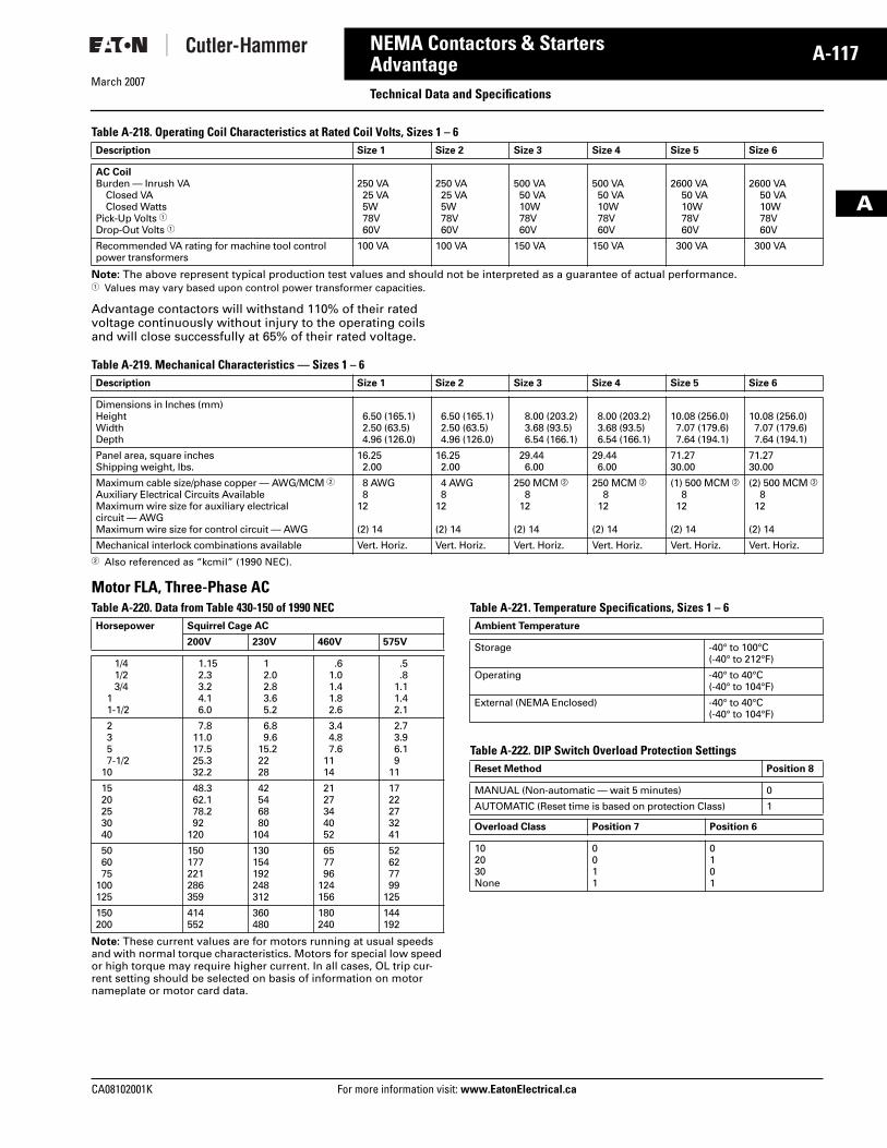
Table A-218. Operating Coil Characteristics at Rated Coil Volts, Sizes 1 – 6
Note: The above represent typical production test values and should not be interpreted as a guarantee of actual performance.� Values may vary based upon control power transformer capacities.
Advantage contactors will withstand 110% of their rated voltage continuously without injury to the operating coils and will close successfully at 65% of their rated voltage.
Table A-219. Mechanical Characteristics — Sizes 1 – 6
� Also referenced as “kcmil” (1990 NEC).
Motor FLA, Three-Phase ACTable A-220. Data from Table 430-150 of 1990 NEC
Note: These current values are for motors running at usual speeds and with normal torque characteristics. Motors for special low speed or high torque may require higher current. In all cases, OL trip cur-rent setting should be selected on basis of information on motor nameplate or motor card data.
Table A-221. Temperature Specifications, Sizes 1 – 6
Table A-222. DIP Switch Overload Protection Settings
Description Size 1 Size 2 Size 3 Size 4 Size 5 Size 6
AC CoilBurden — Inrush VA
Closed VAClosed Watts
Pick-Up Volts �Drop-Out Volts �
250 VA25 VA5W78V60V
250 VA25 VA5W78V60V
500 VA50 VA10W78V60V
500 VA50 VA10W78V60V
2600 VA50 VA10W78V60V
2600 VA50 VA10W78V60V
Recommended VA rating for machine tool control power transformers
100 VA 100 VA 150 VA 150 VA 300 VA 300 VA
Description Size 1 Size 2 Size 3 Size 4 Size 5 Size 6
Dimensions in Inches (mm)HeightWidthDepth
6.50 (165.1)2.50 (63.5)4.96 (126.0)
6.50 (165.1)2.50 (63.5)4.96 (126.0)
8.00 (203.2)3.68 (93.5)6.54 (166.1)
8.00 (203.2)3.68 (93.5)6.54 (166.1)
10.08 (256.0)7.07 (179.6)7.64 (194.1)
10.08 (256.0)7.07 (179.6)7.64 (194.1)
Panel area, square inchesShipping weight, lbs.
16.252.00
16.252.00
29.446.00
29.446.00
71.2730.00
71.2730.00
Maximum cable size/phase copper — AWG/MCM �Auxiliary Electrical Circuits AvailableMaximum wire size for auxiliary electrical circuit — AWGMaximum wire size for control circuit — AWG
8 AWG8
12
(2) 14
4 AWG8
12
(2) 14
250 MCM �8
12
(2) 14
250 MCM �8
12
(2) 14
(1) 500 MCM �8
12
(2) 14
(2) 500 MCM �8
12
(2) 14
Mechanical interlock combinations available Vert. Horiz. Vert. Horiz. Vert. Horiz. Vert. Horiz. Vert. Horiz. Vert. Horiz.
Horsepower Squirrel Cage AC
200V 230V 460V 575V
1/41/23/4
11-1/2
1.152.33.24.16.0
12.02.83.65.2
.61.01.41.82.6
.5
.81.11.42.1
2357-1/2
10
7.811.017.525.332.2
6.89.6
15.22228
3.44.87.6
1114
2.73.96.19
11
1520253040
48.362.178.292
120
42546880
104
2127344052
1722273241
506075
100125
150177221286359
130154192248312
657796
124156
52627799
125
150200
414552
360480
180240
144192
Ambient Temperature
Storage -40° to 100°C(-40° to 212°F)
Operating -40° to 40°C(-40° to 104°F)
External (NEMA Enclosed) -40° to 40°C(-40° to 104°F)
Reset Method Position 8
MANUAL (Non-automatic — wait 5 minutes) 0
AUTOMATIC (Reset time is based on protection Class) 1
Overload Class Position 7 Position 6
102030None
0011
0101
Tab33.book Page 117 Thursday, February 22, 2007 10:27 AM
March 2007
A-118
For more information visit: www.EatonElectrical.ca CA08102001K
NEMA Contactors & Starters
A
AdvantageTechnical Data and Specifications
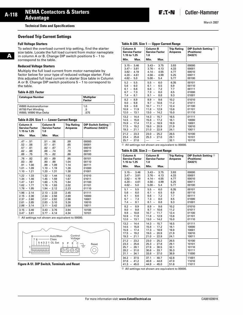
Overload Trip Current Settings
Full Voltage StartersTo select the overload current trip setting, find the starter size table. Locate the full load current from motor nameplate in column A or B. Change DIP switch positions 5 – 1 to correspond to the table.
Reduced Voltage StartersMultiply the full load current from motor nameplate by factor below for your type of reduced voltage starter. Find this adjusted full load current in starter Size table in Column A or B. Change DIP switch positions 5 – 1 to correspond to the table.
Table A-223. Factor
Table A-224. Size 1 — Lower Current Range
� All settings not shown are equivalent to 00000.
Figure A-51. DIP Switch, Terminals and Reset
Table A-225. Size 1 — Upper Current Range
� All settings not shown are equivalent to 00000.
Table A-226. Size 2 — Current Range
� All settings not shown are equivalent to 00000.
Catalogue Number MultiplierFactor
W600 AutotransformerW700 Part WindingW800, W890 Wye-Delta
1.0.5.575
Column AService Factor1.15 to 1.25
Column BService Factor1.0
Trip RatingAmperes
DIP Switch Setting �
(Positions) (54321)
Min. Max. Min. Max.
.47 –
.52 –
.57 –
.62 –
.69 –
.51
.56
.61
.68
.75
.51 –
.57 –
.62 –
.68 –
.75 –
.56
.61
.67
.74
.82
.59
.65
.71
.78
.86
0000000001000100001100100
.76 –
.83 –
.91 –1.01 –1.10 –
.82
.901.001.091.21
.83 –
.90 –
.99 –1.10 –1.20 –
.89
.981.091.191.31
.951.041.141.261.38
0010100110001110100001001
1.22 –1.34 –1.47 –1.62 –1.78 –
1.331.461.611.771.95
1.32 –1.45 –1.60 –1.76 –1.94 –
1.441.591.751.932.12
1.521.671.842.022.23
0101001011011000110101110
1.96 –2.15 –2.37 –2.61 –2.86 –
2.142.362.602.853.14
2.13 –2.34 –2.57 –2.83 –3.11 –
2.332.562.823.103.42
2.452.692.963.263.58
0111110000100011001010011
3.15 –3.47 –
3.463.81
3.43 –3.77 –
3.764.14
3.944.34
1010010101
1
1234567
8
0
Auto/ManClassOL Set 3 P E C
ControlVoltage
Reset
Column AService Factor1.15 to 1.25
Column BService Factor1.0
Trip RatingAmperes
DIP Switch Setting �
(Positions) (54321)
Min. Max. Min. Max.
3.15 –3.47 –3.82 –4.20 –4.62 –
3.463.814.194.615.0
3.43 –3.76 –4.14 –4.56 –5.00 –
3.754.134.554.995.4
3.934.334.775.255.77
0000000001000100001100100
5.2 –5.6 –6.1 –6.7 –7.4 –
5.56.06.67.38.1
5.5 –6.1 –6.6 –7.3 –8.1 –
6.06.57.28.08.8
6.356.97.78.59.3
0010100110001110100001001
8.2 –9.0 –9.9 –
10.9 –12.0 –
8.99.80.811.913.1
8.9 –9.7 –
10.7 –11.8 –13.0 –
9.610.611.712.914.2
10.211.212.413.615.0
0101001011011000110101110
13.2 –14.5 –15.9 –17.5 –19.3 –
14.415.817.419.221.1
14.3 –15.8 –17.3 –19.0 –21.0 –
15.717.218.920.922.9
16.518.119.921.924.1
0111110000100011001010011
21.2 –23.4 –25.7 –
23.325.627.0
23.0 –25.3 –—
25.227.0—
26.529.132.1
101001010110110
Column AService Factor1.15 to 1.25
Column BService Factor1.0
Trip RatingAmperes
DIP Switch Setting �
(Positions) (54321)
Min. Max. Min. Max.
3.15 –3.47 –3.82 –4.20 –4.62 –
3.463.814.194.615.0
3.43 –3.76 –4.14 –4.56 –5.00 –
3.754.134.554.995.4
3.934.334.775.255.77
0000000001000100001100100
5.1 –5.6 –6.1 –6.7 –7.4 –
5.56.06.67.38.1
5.5 –6.1 –6.6 –7.3 –8.1 –
6.06.57.28.08.8
6.356.97.78.59.3
0010100110001110100001001
8.2 –9.0 –9.9 –
10.9 –12.0 –
8.99.8
10.811.913.1
8.9 –9.7 –
10.7 –11.8 –13.0 –
9.610.611.712.914.2
10.211.212.413.615.0
0101001011011000110101110
13.2 –14.5 –15.9 –17.5 –19.3 –
14.415.817.419.221.1
14.3 –15.8 –17.3 –19.0 –21.0 –
15.717.218.920.922.9
16.518.119.921.924.1
0111110000100011001010011
21.2 –23.3 –25.7 –28.2 –31.1 –
23.225.628.131.034.1
23.0 –25.3 –27.9 –30.6 –33.8 –
25.227.830.533.737.0
26.529.132.135.338.9
1010010101101101011111000
34.2 –37.6 –41.3 –
37.541.245.0
37.1 –40.8 –44.9 –
40.744.845.0
42.847.051.6
110011101011011
Tab33.book Page 118 Thursday, February 22, 2007 10:27 AM
March 2007
CA08102001K For more information visit: www.EatonElectrical.ca
A-119NEMA Contactors & Starters
A
AdvantageTechnical Data and Specifications
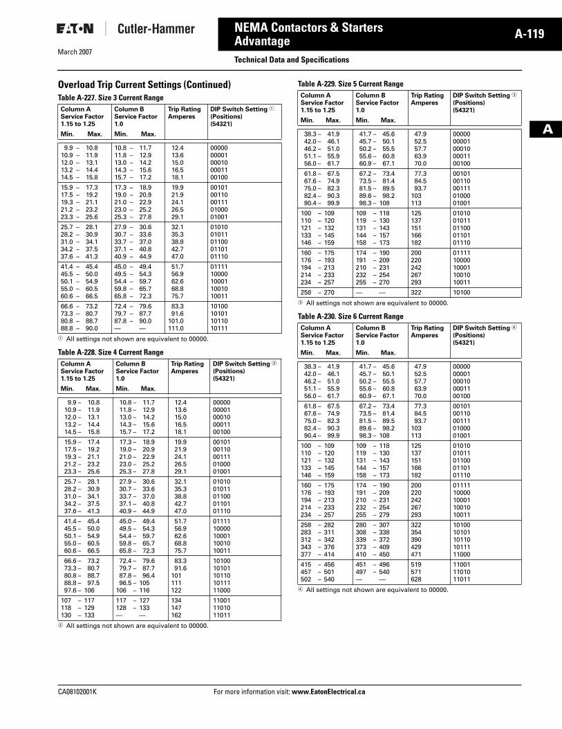
Overload Trip Current Settings (Continued)Table A-227. Size 3 Current Range
� All settings not shown are equivalent to 00000.
Table A-228. Size 4 Current Range
� All settings not shown are equivalent to 00000.
Table A-229. Size 5 Current Range
� All settings not shown are equivalent to 00000.
Table A-230. Size 6 Current Range
� All settings not shown are equivalent to 00000.
Column AService Factor1.15 to 1.25
Column BService Factor1.0
Trip RatingAmperes
DIP Switch Setting �
(Positions) (54321)
Min. Max. Min. Max.
9.9 –10.9 –12.0 –13.2 –14.5 –
10.811.913.114.415.8
10.8 –11.8 –13.0 –14.3 –15.7 –
11.712.914.215.617.2
12.413.615.016.518.1
0000000001000100001100100
15.9 –17.5 –19.3 –21.2 –23.3 –
17.319.221.123.225.6
17.3 –19.0 –21.0 –23.0 –25.3 –
18.920.922.925.227.8
19.921.924.126.529.1
0010100110001110100001001
25.7 –28.2 –31.0 –34.2 –37.6 –
28.130.934.137.541.3
27.9 –30.7 –33.7 –37.1 –40.9 –
30.633.637.040.844.9
32.135.338.842.747.0
0101001011011000110101110
41.4 –45.5 –50.1 –55.0 –60.6 –
45.450.054.960.566.5
45.0 –49.5 –54.4 –59.8 –65.8 –
49.454.359.765.772.3
51.756.962.668.875.7
0111110000100011001010011
66.6 –73.3 –80.8 –88.8 –
73.280.788.790.0
72.4 –79.7 –87.8 –—
79.687.790.0—
83.391.6
101.0111.0
10100101011011010111
Column AService Factor1.15 to 1.25
Column BService Factor1.0
Trip RatingAmperes
DIP Switch Setting �
(Positions) (54321)
Min. Max. Min. Max.
9.9 –10.9 –12.0 –13.2 –14.5 –
10.811.913.114.415.8
10.8 –11.8 –13.0 –14.3 –15.7 –
11.712.914.215.617.2
12.413.615.016.518.1
0000000001000100001100100
15.9 –17.5 –19.3 –21.2 –23.3 –
17.419.221.123.225.6
17.3 –19.0 –21.0 –23.0 –25.3 –
18.920.922.925.227.8
19.921.924.126.529.1
0010100110001110100001001
25.7 –28.2 –31.0 –34.2 –37.6 –
28.130.934.137.541.3
27.9 –30.7 –33.7 –37.1 –40.9 –
30.633.637.040.844.9
32.135.338.842.747.0
0101001011011000110101110
41.4 –45.5 –50.1 –55.0 –60.6 –
45.450.054.960.566.5
45.0 –49.5 –54.4 –59.8 –65.8 –
49.454.359.765.772.3
51.756.962.668.875.7
0111110000100011001010011
66.6 –73.3 –80.8 –88.8 –97.6 –
73.280.788.797.5
106
72.4 –79.7 –87.8 –96.5 –
106 –
79.687.796.4
105116
83.391.6
101111122
1010010101101101011111000
107 –118 –130 –
117129133
117 –128 –—
127133—
134147162
110011101011011
Column AService Factor1.15 to 1.25
Column BService Factor1.0
Trip RatingAmperes
DIP Switch Setting �
(Positions) (54321)
Min. Max. Min. Max.
38.3 –42.0 –46.2 –51.1 –56.0 –
41.946.151.055.961.7
41.7 –45.7 –50.2 –55.6 –60.9 –
45.650.155.560.867.1
47.952.557.763.970.0
0000000001000100001100100
61.8 –67.6 –75.0 –82.4 –90.4 –
67.574.982.390.399.9
67.2 –73.5 –81.5 –89.6 –98.3 –
73.481.489.598.2
108
77.384.593.7
103113
0010100110001110100001001
100 –110 –121 –133 –146 –
109120132145159
109 –119 –131 –144 –158 –
118130143157173
125137151166182
0101001011011000110101110
160 –176 –194 –214 –234 –
175193213233257
174 –191 –210 –232 –255 –
190209231254270
200220242267293
0111110000100011001010011
258 – 270 — — 322 10100
Column AService Factor1.15 to 1.25
Column BService Factor1.0
Trip RatingAmperes
DIP Switch Setting �
(Positions) (54321)
Min. Max. Min. Max.
38.3 –42.0 –46.2 –51.1 –56.0 –
41.946.151.055.961.7
41.7 –45.7 –50.2 –55.6 –60.9 –
45.650.155.560.867.1
47.952.557.763.970.0
0000000001000100001100100
61.8 –67.6 –75.0 –82.4 –90.4 –
67.574.982.390.399.9
67.2 –73.5 –81.5 –89.6 –98.3 –
73.481.489.598.2
108
77.384.593.7
103113
0010100110001110100001001
100 –110 –121 –133 –146 –
109120132145159
109 –119 –131 –144 –158 –
118130143157173
125137151166182
0101001011011000110101110
160 –176 –194 –214 –234 –
175193213233257
174 –191 –210 –232 –255 –
190209231254279
200220242267293
0111110000100011001010011
258 –283 –312 –343 –377 –
282311342376414
280 –308 –339 –373 –410 –
307338372409450
322354390429471
1010010101101101011111000
415 –457 –502 –
456501540
451 –497 –—
496540—
519571628
110011101011011
Tab33.book Page 119 Thursday, February 22, 2007 10:27 AM
March 2007
A-120
For more information visit: www.EatonElectrical.ca CA08102001K
NEMA Contactors & Starters
A
AdvantageTechnical Data and Specifications
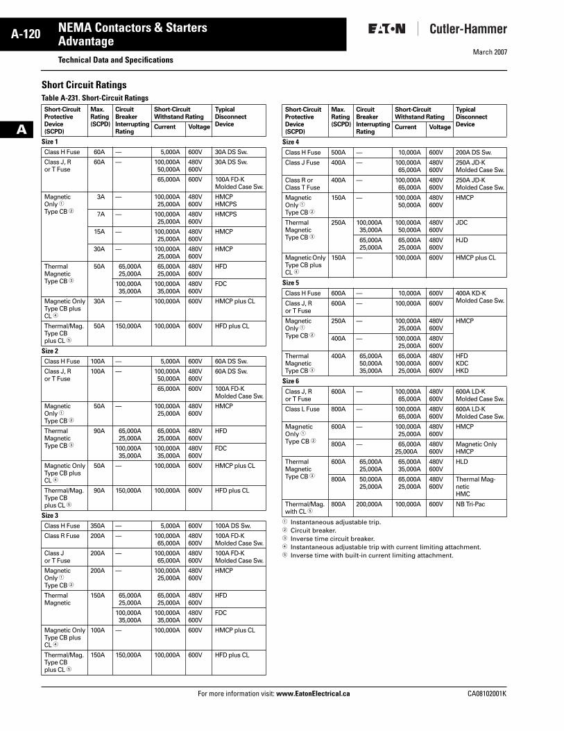
Short Circuit RatingsTable A-231. Short-Circuit Ratings
� Instantaneous adjustable trip.� Circuit breaker.� Inverse time circuit breaker.� Instantaneous adjustable trip with current limiting attachment.� Inverse time with built-in current limiting attachment.
Short-CircuitProtectiveDevice(SCPD)
Max.Rating(SCPD)
CircuitBreakerInterruptingRating
Short-CircuitWithstand Rating
TypicalDisconnectDeviceCurrent Voltage
Size 1Class H Fuse 60A — 5,000A 600V 30A DS Sw.
Class J, Ror T Fuse
60A — 100,000A50,000A
480V600V
30A DS Sw.
65,000A 600V 100A FD-KMolded Case Sw.
MagneticOnly �Type CB �
3A — 100,000A25,000A
480V600V
HMCPHMCPS
7A — 100,000A25,000A
480V600V
HMCPS
15A — 100,000A25,000A
480V600V
HMCP
30A — 100,000A25,000A
480V600V
HMCP
ThermalMagneticType CB �
50A 65,000A25,000A
65,000A25,000A
480V600V
HFD
100,000A35,000A
100,000A35,000A
480V600V
FDC
Magnetic OnlyType CB plusCL �
30A — 100,000A 600V HMCP plus CL
Thermal/Mag.Type CBplus CL �
50A 150,000A 100,000A 600V HFD plus CL
Size 2Class H Fuse 100A — 5,000A 600V 60A DS Sw.
Class J, Ror T Fuse
100A — 100,000A50,000A
480V600V
60A DS Sw.
65,000A 600V 100A FD-KMolded Case Sw.
MagneticOnly �Type CB �
50A — 100,000A25,000A
480V600V
HMCP
ThermalMagneticType CB �
90A 65,000A25,000A
65,000A25,000A
480V600V
HFD
100,000A35,000A
100,000A35,000A
480V600V
FDC
Magnetic OnlyType CB plusCL �
50A — 100,000A 600V HMCP plus CL
Thermal/Mag.Type CBplus CL �
90A 150,000A 100,000A 600V HFD plus CL
Size 3Class H Fuse 350A — 5,000A 600V 100A DS Sw.
Class R Fuse 200A — 100,000A65,000A
480V600V
100A FD-K Molded Case Sw.
Class J or T Fuse
200A — 100,000A65,000A
480V600V
100A FD-KMolded Case Sw.
MagneticOnly �Type CB �
200A — 100,000A25,000A
480V600V
HMCP
ThermalMagnetic
150A 65,000A25,000A
65,000A25,000A
480V600V
HFD
100,000A35,000A
100,000A35,000A
480V600V
FDC
Magnetic OnlyType CB plusCL �
100A — 100,000A 600V HMCP plus CL
Thermal/Mag.Type CBplus CL �
150A 150,000A 100,000A 600V HFD plus CL
Short-CircuitProtectiveDevice(SCPD)
Max.Rating(SCPD)
CircuitBreakerInterruptingRating
Short-CircuitWithstand Rating
TypicalDisconnectDeviceCurrent Voltage
Size 4Class H Fuse 500A — 10,000A 600V 200A DS Sw.
Class J Fuse 400A — 100,000A65,000A
480V600V
250A JD-K Molded Case Sw.
Class R or Class T Fuse
400A — 100,000A65,000A
480V600V
250A JD-K Molded Case Sw.
MagneticOnly �Type CB �
150A — 100,000A50,000A
480V600V
HMCP
ThermalMagneticType CB �
250A 100,000A35,000A
100,000A50,000A
480V600V
JDC
65,000A25,000A
65,000A25,000A
480V600V
HJD
Magnetic Only Type CB plus CL �
150A — 100,000A 600V HMCP plus CL
Size 5Class H Fuse 600A — 10,000A 600V 400A KD-K
Molded Case Sw.Class J, Ror T Fuse
600A — 100,000A 600V
MagneticOnly �Type CB �
250A — 100,000A25,000A
480V600V
HMCP
400A — 100,000A25,000A
480V600V
ThermalMagneticType CB �
400A 65,000A50,000A35,000A
65,000A100,000A25,000A
480V600V600V
HFDKDCHKD
Size 6Class J, Ror T Fuse
600A — 100,000A65,000A
480V600V
600A LD-K Molded Case Sw.
Class L Fuse 800A — 100,000A65,000A
480V600V
600A LD-K Molded Case Sw.
MagneticOnly �Type CB �
600A — 100,000A25,000A
480V600V
HMCP
800A — 65,000A25,000A
480V600V
Magnetic OnlyHMCP
ThermalMagneticType CB �
600A 65,000A25,000A
65,000A35,000A
480V600V
HLD
800A 50,000A25,000A
65,000A25,000A
480V600V
Thermal Mag-neticHMC
Thermal/Mag.with CL �
800A 200,000A 100,000A 600V NB Tri-Pac
Tab33.book Page 120 Thursday, February 22, 2007 10:27 AM
March 2007
CA08102001K For more information visit: www.EatonElectrical.ca
A-121NEMA Contactors & Starters
A
AdvantageAccessories
DeviceNet™ Communications Module
DeviceNet Module
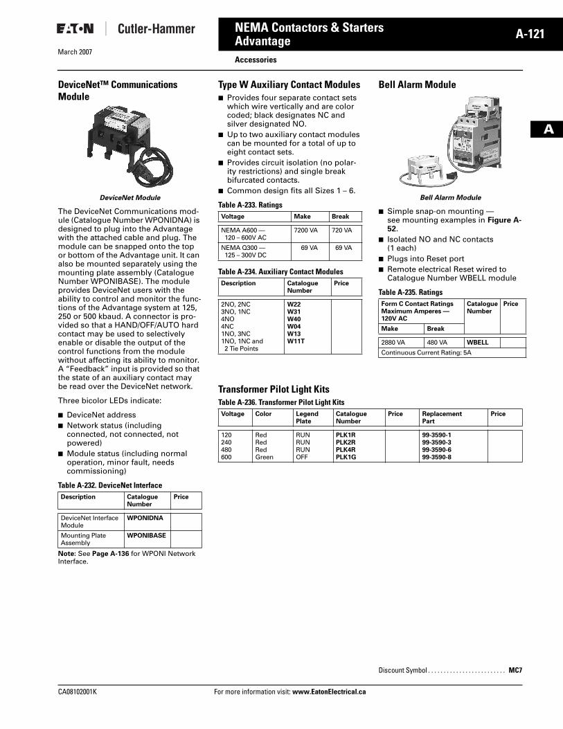
The DeviceNet Communications mod-ule (Catalogue Number WPONIDNA) is designed to plug into the Advantage with the attached cable and plug. The module can be snapped onto the top or bottom of the Advantage unit. It can also be mounted separately using the mounting plate assembly (Catalogue Number WPONIBASE). The module provides DeviceNet users with the ability to control and monitor the func-tions of the Advantage system at 125, 250 or 500 kbaud. A connector is pro-vided so that a HAND/OFF/AUTO hard contact may be used to selectively enable or disable the output of the control functions from the module without affecting its ability to monitor. A “Feedback” input is provided so that the state of an auxiliary contact may be read over the DeviceNet network.
Three bicolor LEDs indicate:
� DeviceNet address� Network status (including
connected, not connected, not powered)
� Module status (including normal operation, minor fault, needs commissioning)
Table A-232. DeviceNet Interface
Note: See Page A-136 for WPONI Network Interface.
Description CatalogueNumber
Price
DeviceNet InterfaceModule
WPONIDNA
Mounting Plate Assembly
WPONIBASE
Type W Auxiliary Contact Modules� Provides four separate contact sets
which wire vertically and are color coded; black designates NC and silver designated NO.
� Up to two auxiliary contact modules can be mounted for a total of up to eight contact sets.
� Provides circuit isolation (no polar-ity restrictions) and single break bifurcated contacts.
� Common design fits all Sizes 1 – 6.
Table A-233. Ratings
Table A-234. Auxiliary Contact Modules
Bell Alarm Module
Bell Alarm Module
� Simple snap-on mounting —see mounting examples in Figure A-52.
� Isolated NO and NC contacts (1 each)
� Plugs into Reset port� Remote electrical Reset wired to
Catalogue Number WBELL module
Table A-235. Ratings
Transformer Pilot Light KitsTable A-236. Transformer Pilot Light Kits
Voltage Make Break
NEMA A600 — 120 – 600V AC
7200 VA 720 VA
NEMA Q300 — 125 – 300V DC
69 VA 69 VA
Description CatalogueNumber
Price
2NO, 2NC3NO, 1NC4NO4NC1NO, 3NC1NO, 1NC and 2 Tie Points
W22W31W40W04W13W11T
Form C Contact RatingsMaximum Amperes — 120V AC
CatalogueNumber
Price
Make Break
2880 VA 480 VA WBELL
Continuous Current Rating: 5A
Voltage Color LegendPlate
CatalogueNumber
Price ReplacementPart
Price
120240480600
RedRedRedGreen
RUNRUNRUNOFF
PLK1RPLK2RPLK4RPLK1G
99-3590-199-3590-399-3590-699-3590-8
Discount Symbol . . . . . . . . . . . . . . . . . . . . . . . . . MC7
Tab33.book Page 121 Thursday, February 22, 2007 10:27 AM
March 2007
A-122
For more information visit: www.EatonElectrical.ca CA08102001K
NEMA Contactors & Starters
A
AdvantageAccessories
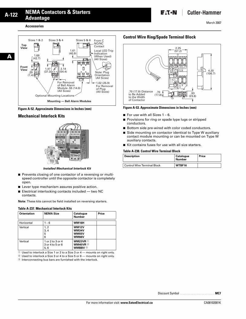
Figure A-52. Approximate Dimensions in Inches (mm)
Mechanical Interlock Kits
Installed Mechanical Interlock Kit
� Prevents closing of one contactor of a reversing or multi-speed controller until the opposite contactor is completely open.
� Lever type mechanism assures positive action.� Electrical interlocking contacts included — two NC
contacts.
Note: These kits cannot be field installed on reversing starters.
Table A-237. Mechanical Interlock Kits
� Used to interlock a Size 1 or 2 to a Size 3 or 4 — mounts on right only.� Used to interlock a Size 3 or 4 to a Size 5 or 6 — mounts on right only.� Interconnecting bus bars are furnished with the interlock.
Control Wire Ring/Spade Terminal Block
Figure A-53. Approximate Dimensions in Inches (mm)
� For use with all Sizes 1 – 6.� Provisions for ring or spade type lugs or stripped
conductors.� Bottom side pre-wired with color coded conductors.� Side mounting on contactor identical to Type W auxiliary
contact module mounting or can be mounted on Type W auxiliary contacts.
� Kit contains fuses for use with all size starters.
Table A-238. Control Wire Terminal Block
Orientation NEMA Size Catalogue Number
Price
Horizontal 1 – 6 WM16H
Vertical 1, 23, 456
WM12VWM34VWM55VWM66V
Vertical 1 or 2 to 3 or 43 or 4 to 5 or 65, 6
WM23VR �
WM45VR �
WMBBV �
Sizes 1 & 2 Sizes 3 & 4 Sizes 5 & 6
1.68(42.7)
1.47(37.3)
2.14(54.4)
1.61(40.9)
.29(7.4)
1.02 (25.9)For Removalof Plug(All Sizes)
For Removalof Bell AlarmModule .55 (14.0)(All Sizes)
Optional Mounting Locations
Local LED TripIndication(When Used)(All Sizes)
From CNO/NCContact
Note: PlugOrientation(All Sizes)
TopView
FrontView
Mounting — Bell Alarm Modules
Description CatalogueNumber
Price
Control Wire Terminal Block WTBF16
Discount Symbol . . . . . . . . . . . . . . . . . . . . . . . . . MC7
2.25(57.2)
.70(17.8) .93
(23.6)
4.20(106.7)
.70 (17.8) Distanceto Be Addedto the Widthof Contactor
Tab33.book Page 122 Thursday, February 22, 2007 10:27 AM
March 2007
CA08102001K For more information visit: www.EatonElectrical.ca
A-123NEMA Contactors & Starters
A
AdvantageAccessories
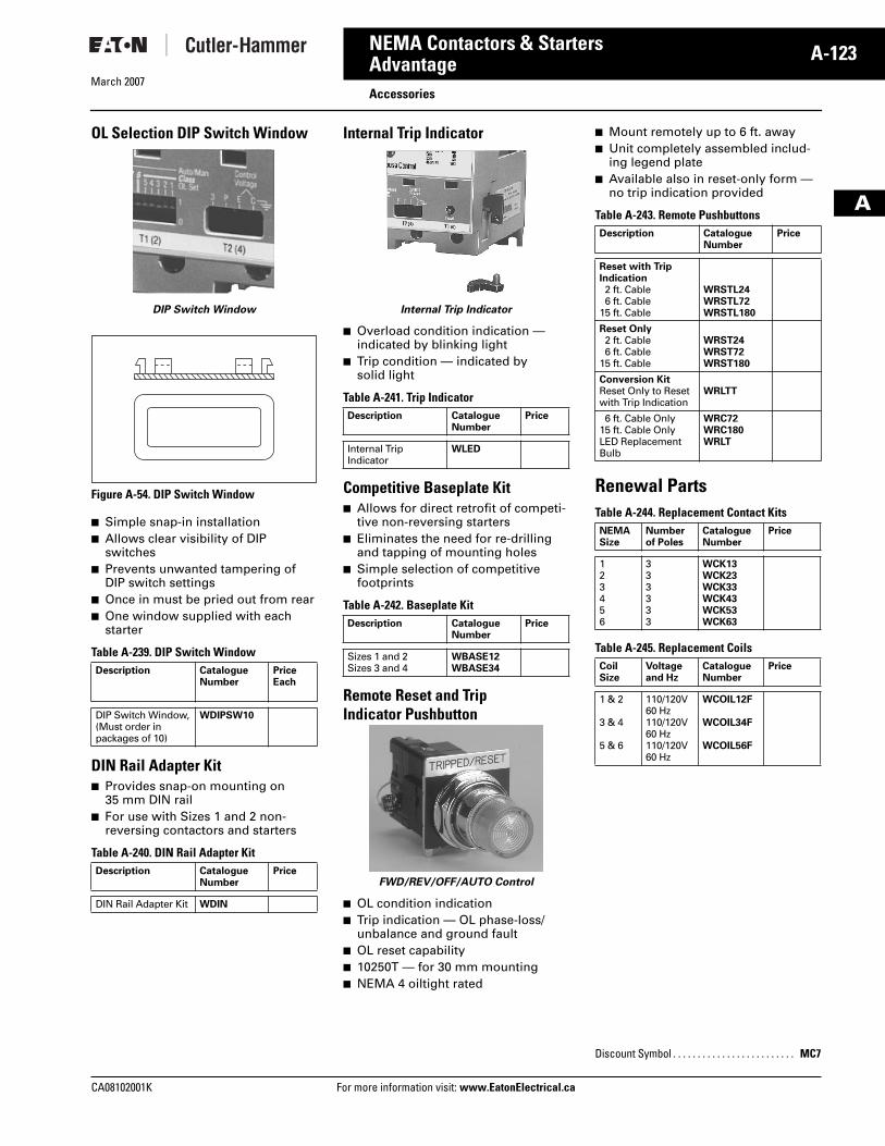
OL Selection DIP Switch Window
DIP Switch Window
Figure A-54. DIP Switch Window
� Simple snap-in installation� Allows clear visibility of DIP
switches� Prevents unwanted tampering of
DIP switch settings� Once in must be pried out from rear� One window supplied with each
starter
Table A-239. DIP Switch Window
DIN Rail Adapter Kit� Provides snap-on mounting on
35 mm DIN rail� For use with Sizes 1 and 2 non-
reversing contactors and starters
Table A-240. DIN Rail Adapter Kit
Internal Trip Indicator
Internal Trip Indicator
� Overload condition indication — indicated by blinking light
� Trip condition — indicated by solid light
Table A-241. Trip Indicator
Competitive Baseplate Kit� Allows for direct retrofit of competi-
tive non-reversing starters� Eliminates the need for re-drilling
and tapping of mounting holes� Simple selection of competitive
footprints
Table A-242. Baseplate Kit
Remote Reset and Trip Indicator Pushbutton
FWD/REV/OFF/AUTO Control
� OL condition indication� Trip indication — OL phase-loss/
unbalance and ground fault� OL reset capability� 10250T — for 30 mm mounting� NEMA 4 oiltight rated
� Mount remotely up to 6 ft. away� Unit completely assembled includ-
ing legend plate� Available also in reset-only form —
no trip indication provided
Table A-243. Remote Pushbuttons
Renewal PartsTable A-244. Replacement Contact Kits
Table A-245. Replacement Coils
Description CatalogueNumber
Price Each
DIP Switch Window, (Must order in packages of 10)
WDIPSW10
Description CatalogueNumber
Price
DIN Rail Adapter Kit WDIN
Description CatalogueNumber
Price
Internal TripIndicator
WLED
Description CatalogueNumber
Price
Sizes 1 and 2Sizes 3 and 4
WBASE12WBASE34
Description CatalogueNumber
Price
Reset with Trip Indication2 ft. Cable6 ft. Cable
15 ft. Cable
WRSTL24WRSTL72WRSTL180
Reset Only2 ft. Cable6 ft. Cable
15 ft. Cable
WRST24WRST72WRST180
Conversion KitReset Only to Reset with Trip Indication
WRLTT
6 ft. Cable Only15 ft. Cable OnlyLED Replacement Bulb
WRC72WRC180WRLT
NEMASize
Numberof Poles
CatalogueNumber
Price
123456
333333
WCK13WCK23WCK33WCK43WCK53WCK63
CoilSize
Voltage and Hz
CatalogueNumber
Price
1 & 2
3 & 4
5 & 6
110/120V 60 Hz110/120V 60 Hz110/120V 60 Hz
WCOIL12F
WCOIL34F
WCOIL56F
Discount Symbol . . . . . . . . . . . . . . . . . . . . . . . . . MC7
Tab33.book Page 123 Thursday, February 22, 2007 10:27 AM
March 2007
A-124
For more information visit: www.EatonElectrical.ca CA08102001K
NEMA Contactors & Starters
A
AdvantageAdvantage Control Modules
Cutler-Hammer® Advantage Control Modules (ACMs) from Eaton’s electrical business provide a cost-effective alter-native to pushbuttons, selector switches, indicating lights, reset mech-anisms, bell alarms and panel meters when used with the Advantage prod-uct line. Typical input/output control functions provided by panel mounted devices are conveniently packaged in a series of modules depending on appli-cation and complexity.
Sixteen styles cover applications ranging from:
� Full voltage non-reversing� Full voltage reversing� Full voltage multispeed� Reduced voltage� DeviceNet compatible
Modules exist for each application to provide the functions of:
� Status only❑ Indicating lights❑ Reset
� Status, START/STOP and RESET� Status, HOA and RESET� Status, START/STOP/HOA and
RESET
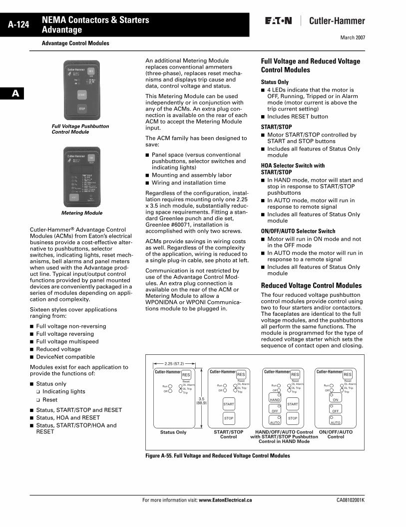
Full Voltage PushbuttonControl Module
Metering Module
An additional Metering Module replaces conventional ammeters (three-phase), replaces reset mecha-nisms and displays trip cause and data, control voltage and status.
This Metering Module can be used independently or in conjunction with any of the ACMs. An extra plug con-nection is available on the rear of each ACM to accept the Metering Module input.
The ACM family has been designed to save:
� Panel space (versus conventional pushbuttons, selector switches and indicating lights)
� Mounting and assembly labor� Wiring and installation time
Regardless of the configuration, instal-lation requires mounting only one 2.25 x 3.5 inch module, substantially reduc-ing space requirements. Fitting a stan-dard Greenlee punch and die set, Greenlee #60071, installation is accomplished with only two screws.
ACMs provide savings in wiring costs as well. Regardless of the complexity of the application, wiring is reduced to a single plug-in cable, see photo at left.
Communication is not restricted by use of the Advantage Control Mod-ules. An extra plug connection is available on the rear of the ACM or Metering Module to allow a WPONIDNA or WPONI Communica-tions module to be plugged in.
Full Voltage and Reduced Voltage Control Modules
Status Only� 4 LEDs indicate that the motor is
OFF, Running, Tripped or in Alarm mode (motor current is above the trip current setting)
� Includes RESET button
START/STOP� Motor START/STOP controlled by
START and STOP buttons� Includes all features of Status Only
module
HOA Selector Switch with START/STOP� In HAND mode, motor will start and
stop in response to START/STOP pushbuttons
� In AUTO mode, motor will run in response to remote signal
� Includes all features of Status Only module
ON/OFF/AUTO Selector Switch� Motor will run in ON mode and not
in the OFF mode� In AUTO mode the motor will run in
response to a remote signal� Includes all features of Status Only
module
Reduced Voltage Control ModulesThe four reduced voltage pushbutton control modules provide control using two to four starters and/or contactors. The faceplates are identical to the full voltage modules, and the pushbuttons all perform the same functions. The module is programmed for the type of reduced voltage starter which sets the sequence of contact open and closing.
Figure A-55. Full Voltage and Reduced Voltage Control Modules
OL Alarm
TripOL Trip
OL Alarm
TripOL Trip
OL Alarm
TripOL Trip
RES
Reset
Run
Off
OL Alarm
TripOL Trip
RESReset
RESReset
RESReset
Run
Off
Run
HANDSTART
STOP
START
STOP
OFF
AUTO
ON
OFF
AUTO
Off
Run
Off
Status Only START/STOPControl
HAND/OFF/AUTO Controlwith START/STOP Pushbutton
Control in HAND Mode
ON/OFF/AUTOControl
3.5(88.9)
2.25 (57.2)
Tab33.book Page 124 Thursday, February 22, 2007 10:27 AM
March 2007
CA08102001K For more information visit: www.EatonElectrical.ca
A-125NEMA Contactors & Starters
A
AdvantageAdvantage Control Modules
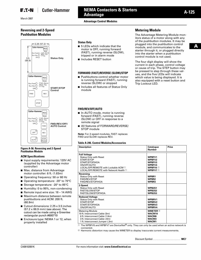
Reversing and 2-Speed Pushbutton Modules
Figure A-56. Reversing and 2-Speed Pushbutton Module
ACM Specifications� Input supply requirements: 120V AC
(supplied by the Advantage motor controller)
� Max. distance from Advantage motor controller: 6 ft. (1.83m)
� Operating frequency: 50 or 60 Hz� Operating temperature: -20° to 70°C� Storage temperature: -20° to 85°C� Humidity: 0 to 95%, non-condensing� Remote input wire size: 18 – 14 AWG� Maximum distance between remote
pushbuttons and ACM: 200 ft. (60.9m)
� Cutout dimensions: 2.25 x 3.5 inches (57.2 x 88.9 mm) (see above). The cutout can be made using a Greenlee rectangular punch #600710
� Enclosure type: NEMA 1 or 12, when properly installed
RESReset
Run Fwd
Run RevOff
OL Alarm
TripOL Trip
Status Only
RES
Reset
REVFWD
STOP
Run Fwd
Run Rev
Off
OL Alarm
TripOL Trip
START/STOPControl
RES
Reset
REV
AUTO
OFF
STOP
HAND
FWD
Run Fwd
Run Rev
Off
OL Alarm
TripOL Trip
FWD/REV/OFF/AUTO Control
3.5(88.9)
2.25 (57.2)Status Only� 5 LEDs which indicate that the
motor is OFF, running forward (FAST), running reverse (SLOW), tripped or in alarm mode
� Includes RESET button
FORWARD (FAST)/REVERSE (SLOW)/STOP� Pushbuttons control whether motor
is running forward (FAST), running reverse (SLOW) or stopped
� Includes all features of Status Only module
FWD/REV/OFF/AUTO� In AUTO mode, motor is running
forward (FAST), running reverse (SLOW) or OFF in response to a remote signal
� All features of FORWARD/REVERSE/STOP module
Note: For 2-speed modules, FAST replaces FWD and SLOW replaces REV.
Metering ModuleThe Advantage Metering Module mon-itors status of a motor along with any of the pushbutton modules. It may be plugged into the pushbutton control module, and communicates to the starter through it, or plugged directly into the starter when a pushbutton control module is not used.
The four digit display will show the current in each phase, control voltage or cause of trip. The STEP button may be pressed to step through these val-ues, and the five LEDs will indicate which value is being displayed. It is also equipped with a reset button and Trip Lockout LED.
Table A-246. Control Modules/Accessories
� The WPBFV5 and WPBFV7 are DeviceNet® only. They can only be used when an active network is connected.
� Harmonic distortion may cause the WMETER to display inaccurate current measurements.
Description CatalogueNumber
Price
Full VoltageStatus Only with ResetSTART/STOPSTART/STOP/HOAON/OFF/AUTOLOCAL/OFF/REMOTE with Lockable ACM �LOCAL/OFF/REMOTE with Network Health �
WPBFV1WPBFV2WPBFV3WPBFV4WPBFV5 �
WPBFV7 �
ReversingStatus Only with ResetFWD/REV/STOPFWD/REV/STOP/HOA
WPBR1WPBR2WPBR3
2-SpeedStatus Only with ResetFAST/SLOW/STOPFAST/SLOW/STOP/HOA
WPB2S1WPB2S2WPB2S3
Reduced VoltageStatus Only with ResetSTART/STOPSTART/STOP/HOAON/OFF/AUTO
WPBRV1WPBRV2WPBRV3WPBRV4
Metering Module10 ft. Interconnect Cable (3m)6 ft. Interconnect Cable (1.8m)3 ft. Interconnect Cable (.9m)1 ft. Interconnect Jumper (.3m)
WMETER �
WACM10WACM6WACM3WACM1
Discount Symbol . . . . . . . . . . . . . . . . . . . . . . . . . MC7
Tab33.book Page 125 Thursday, February 22, 2007 10:27 AM
March 2007
A-126
For more information visit: www.EatonElectrical.ca CA08102001K
NEMA Contactors & Starters
A
AdvantageDimensions
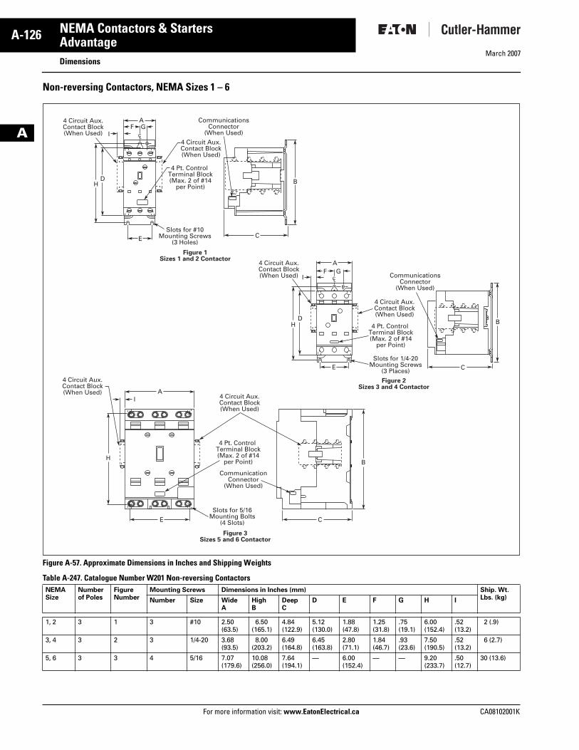
Non-reversing Contactors, NEMA Sizes 1 – 6
Figure A-57. Approximate Dimensions in Inches and Shipping Weights
Table A-247. Catalogue Number W201 Non-reversing Contactors NEMA Size
Numberof Poles
FigureNumber
Mounting Screws Dimensions in Inches (mm) Ship. Wt. Lbs. (kg)Number Size Wide
AHighB
DeepC
D E F G H I
1, 2 3 1 3 #10 2.50(63.5)
6.50(165.1)
4.84(122.9)
5.12(130.0)
1.88 (47.8)
1.25(31.8)
.75(19.1)
6.00(152.4)
.52(13.2)
2 (.9)
3, 4 3 2 3 1/4-20 3.68(93.5)
8.00(203.2)
6.49(164.8)
6.45(163.8)
2.80(71.1)
1.84(46.7)
.93(23.6)
7.50(190.5)
.52(13.2)
6 (2.7)
5, 6 3 3 4 5/16 7.07(179.6)
10.08(256.0)
7.64(194.1)
— 6.00(152.4)
— — 9.20(233.7)
.50(12.7)
30 (13.6)
AF G
I
H
E
BD
CSlots for #10
Mounting Screws(3 Holes)
CommunicationsConnector
(When Used)
4 Pt. Control Terminal Block(Max. 2 of #14
per Point)
4 Circuit Aux.Contact Block(When Used)
4 Circuit Aux.Contact Block(When Used)
CL
AI
H
E
B
C
Slots for 5/16Mounting Bolts
(4 Slots)
CommunicationConnector
(When Used)
4 Pt. Control Terminal Block(Max. 2 of #14
per Point)
4 Circuit Aux.Contact Block(When Used)
4 Circuit Aux.Contact Block(When Used)
Figure 3Sizes 5 and 6 Contactor
AF G
I
H
E
BD
CSlots for 1/4-20
Mounting Screws(3 Places)
CommunicationsConnector
(When Used)
4 Pt. Control Terminal Block(Max. 2 of #14
per Point)
4 Circuit Aux.Contact Block(When Used)
4 Circuit Aux.Contact Block(When Used)
CL
Figure 2Sizes 3 and 4 Contactor
Figure 1Sizes 1 and 2 Contactor
Tab33.book Page 126 Thursday, February 22, 2007 10:27 AM
March 2007
CA08102001K For more information visit: www.EatonElectrical.ca
A-127NEMA Contactors & Starters
A
AdvantageDimensions
Horizontal Reversing, Open Contactors, NEMA Sizes 1 – 6
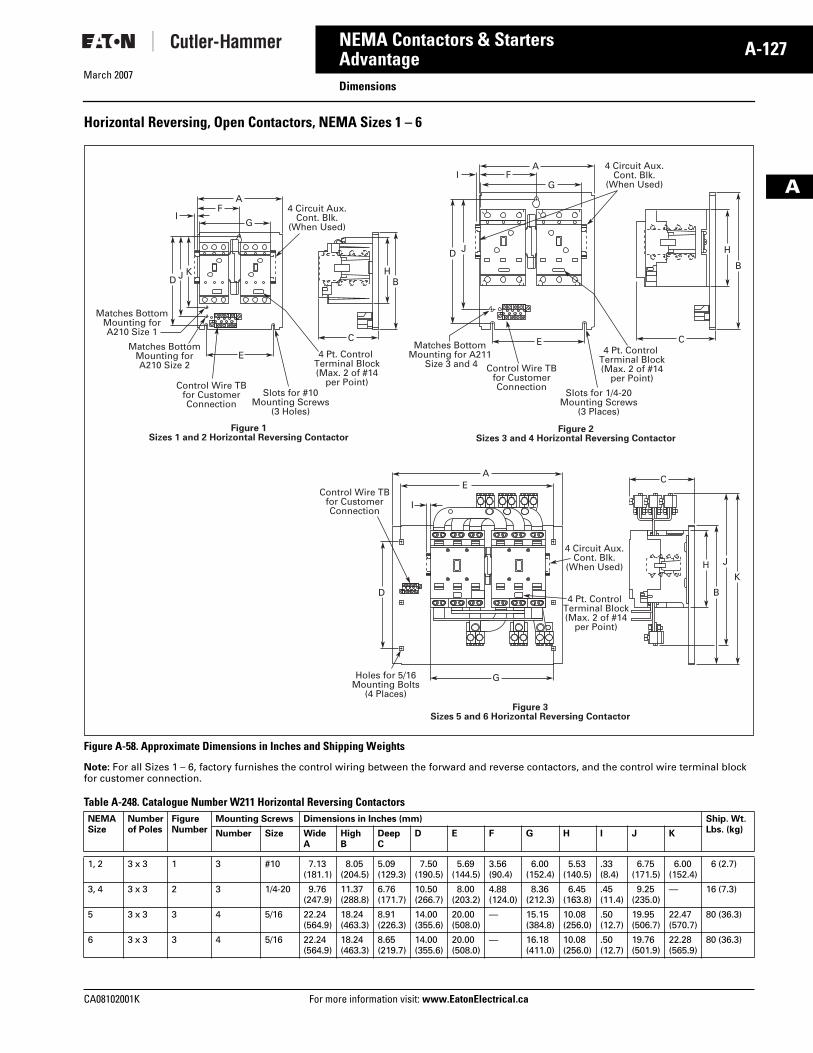
Figure A-58. Approximate Dimensions in Inches and Shipping Weights
Note: For all Sizes 1 – 6, factory furnishes the control wiring between the forward and reverse contactors, and the control wire terminal block for customer connection.
Table A-248. Catalogue Number W211 Horizontal Reversing Contactors NEMA Size
Numberof Poles
FigureNumber
Mounting Screws Dimensions in Inches (mm) Ship. Wt. Lbs. (kg)Number Size Wide
AHighB
DeepC
D E F G H I J K
1, 2 3 x 3 1 3 #10 7.13(181.1)
8.05(204.5)
5.09(129.3)
7.50(190.5)
5.69(144.5)
3.56(90.4)
6.00(152.4)
5.53(140.5)
.33(8.4)
6.75(171.5)
6.00(152.4)
6 (2.7)
3, 4 3 x 3 2 3 1/4-20 9.76(247.9)
11.37(288.8)
6.76(171.7)
10.50(266.7)
8.00(203.2)
4.88(124.0)
8.36(212.3)
6.45(163.8)
.45(11.4)
9.25(235.0)
— 16 (7.3)
5 3 x 3 3 4 5/16 22.24(564.9)
18.24(463.3)
8.91(226.3)
14.00(355.6)
20.00(508.0)
— 15.15(384.8)
10.08(256.0)
.50(12.7)
19.95(506.7)
22.47(570.7)
80 (36.3)
6 3 x 3 3 4 5/16 22.24(564.9)
18.24(463.3)
8.65(219.7)
14.00(355.6)
20.00(508.0)
— 16.18(411.0)
10.08(256.0)
.50(12.7)
19.76(501.9)
22.28(565.9)
80 (36.3)
AF
D J K
IG
E
C
BH
4 Circuit Aux.Cont. Blk.
(When Used)
Control Wire TBfor CustomerConnection
Matches BottomMounting forA210 Size 2
Matches BottomMounting forA210 Size 1
Slots for #10Mounting Screws
(3 Holes)
4 Pt. Control Terminal Block(Max. 2 of #14
per Point)
AF
D J
IG
E C
B
H
4 Circuit Aux.Cont. Blk.
(When Used)
Control Wire TBfor CustomerConnection
Matches BottomMounting for A211
Size 3 and 4
Slots for 1/4-20Mounting Screws
(3 Places)
4 Pt. Control Terminal Block(Max. 2 of #14
per Point)
Figure 1Sizes 1 and 2 Horizontal Reversing Contactor
Figure 2Sizes 3 and 4 Horizontal Reversing Contactor
AE
C
I
D
G
B
HK
J4 Circuit Aux.
Cont. Blk.(When Used)
Control Wire TBfor CustomerConnection
Holes for 5/16Mounting Bolts
(4 Places)
4 Pt. Control Terminal Block(Max. 2 of #14
per Point)
Figure 3Sizes 5 and 6 Horizontal Reversing Contactor
Tab33.book Page 127 Thursday, February 22, 2007 10:27 AM
March 2007
A-128
For more information visit: www.EatonElectrical.ca CA08102001K
NEMA Contactors & Starters
A
AdvantageDimensions
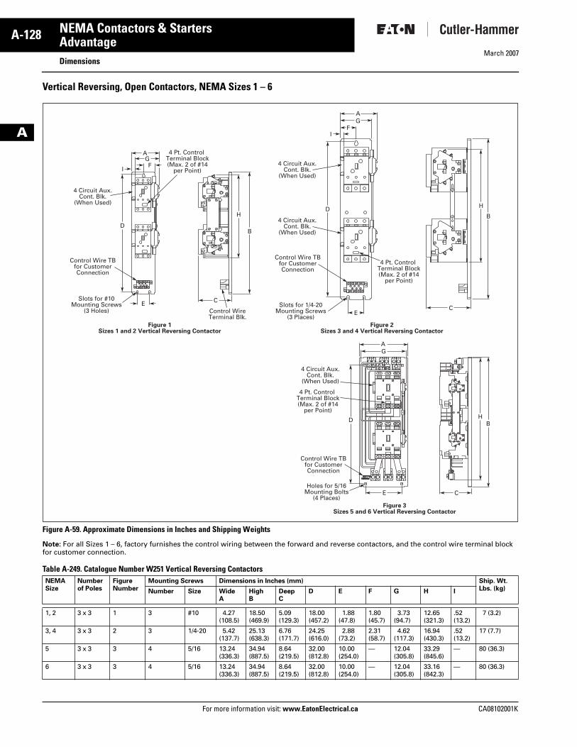
Vertical Reversing, Open Contactors, NEMA Sizes 1 – 6
Figure A-59. Approximate Dimensions in Inches and Shipping Weights
Note: For all Sizes 1 – 6, factory furnishes the control wiring between the forward and reverse contactors, and the control wire terminal block for customer connection.
Table A-249. Catalogue Number W251 Vertical Reversing Contactors NEMA Size
Numberof Poles
FigureNumber
Mounting Screws Dimensions in Inches (mm) Ship. Wt. Lbs. (kg)Number Size Wide
AHighB
DeepC
D E F G H I
1, 2 3 x 3 1 3 #10 4.27(108.5)
18.50(469.9)
5.09(129.3)
18.00(457.2)
1.88(47.8)
1.80(45.7)
3.73(94.7)
12.65(321.3)
.52(13.2)
7 (3.2)
3, 4 3 x 3 2 3 1/4-20 5.42(137.7)
25.13(638.3)
6.76(171.7)
24.25(616.0)
2.88(73.2)
2.31(58.7)
4.62(117.3)
16.94(430.3)
.52(13.2)
17 (7.7)
5 3 x 3 3 4 5/16 13.24(336.3)
34.94(887.5)
8.64(219.5)
32.00(812.8)
10.00(254.0)
— 12.04(305.8)
33.29(845.6)
— 80 (36.3)
6 3 x 3 3 4 5/16 13.24(336.3)
34.94(887.5)
8.64(219.5)
32.00(812.8)
10.00(254.0)
— 12.04(305.8)
33.16(842.3)
— 80 (36.3)
AGF
I
D
E C
B
H
4 Circuit Aux.Cont. Blk.
(When Used)
Control Wire TBfor CustomerConnection
Slots for #10Mounting Screws
(3 Holes) Control WireTerminal Blk.
4 Pt. Control Terminal Block(Max. 2 of #14
per Point)
AG
FI
D
EC
B
H
4 Circuit Aux.Cont. Blk.
(When Used)
4 Circuit Aux.Cont. Blk.
(When Used)
Control Wire TBfor CustomerConnection
Slots for 1/4-20Mounting Screws
(3 Places)
4 Pt. Control Terminal Block(Max. 2 of #14
per Point)
Figure 2Sizes 3 and 4 Vertical Reversing Contactor
Figure 1Sizes 1 and 2 Vertical Reversing Contactor
AG
D
CE
BH
4 Circuit Aux.Cont. Blk.
(When Used)
Control Wire TBfor CustomerConnection
Holes for 5/16Mounting Bolts
(4 Places)
4 Pt. Control Terminal Block(Max. 2 of #14
per Point)
Figure 3Sizes 5 and 6 Vertical Reversing Contactor
Tab33.book Page 128 Thursday, February 22, 2007 10:27 AM
March 2007
CA08102001K For more information visit: www.EatonElectrical.ca
A-129NEMA Contactors & Starters
A
AdvantageDimensions
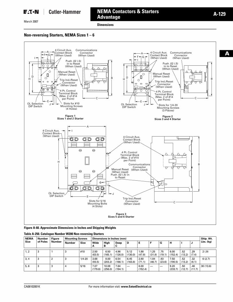
Non-reversing Starters, NEMA Sizes 1 – 6
Figure A-60. Approximate Dimensions in Inches and Shipping Weights
Table A-250. Catalogue Number W200 Non-reversing Starters NEMA Size
Numberof Poles
FigureNumber
Mounting Screws Dimensions in Inches (mm) Ship. Wt. Lbs. (kg)Number Size Wide
AHighB
DeepC
D E F G H I J
1, 2 3 1 3 #10 2.50(63.5)
6.50(165.1)
4.96(126.0)
5.12(130.0)
1.88(47.8)
1.25(31.8)
.75(19.1)
6.00(152.4)
.52(13.2)
.29(7.4)
2 (.9)
3, 4 3 2 3 1/4-20 3.68(93.5)
8.00(203.2)
6.54(166.1)
6.45(163.8)
2.80(71.1)
1.84(46.7)
.93(23.6)
7.50(190.5)
.52(13.2)
.32(8.1)
6 (2.7)
5, 6 3 3 4 5/16 7.07(179.6)
10.08(256.0)
7.64(194.1)
— 6.00(152.4)
— — 9.20(233.7)
.50(12.7)
.46(11.7)
30 (13.6)
AF G
I
H
JE
BD
C
OL SelectionDIP Switch
Slots for #10Mounting Screws
(4 Holes)
Trip Ind./ResetConnector
(When Used)
Manual Reset(When Used)
CommunicationsConnector
(When Used)
4 Pt. Control Terminal Block(Max. 2 of #14
per Point)
4 Circuit Aux.Contact Block(When Used)
Push .02 (.5)in to Reset
(When Used)
CL
A
I
H
EJ
B
C
OL SelectionDIP Switch
Slots for 5/16Mounting Bolts
(4 Slots)
Trip Ind./ResetConnector
(When Used)
Manual Reset(When Used)
Push .02 (.5) into Reset
CommunicationsConnector
(When Used)
4 Pt. Control Terminal Block(Max. 2 of #14
per Point)
4 Circuit Aux.Contact Block(When Used)
4 Circuit Aux.Contact Block(When Used)
AF GI
H
JE
BD
C
OL SelectionDIP Switch
Figure 2Sizes 3 and 4 Starter
Figure 3Sizes 5 and 6 Starter
Figure 1Sizes 1 and 2 Starter
Slots for 1/4-20Mounting Screws
(3 Places)
Trip Ind./ResetConnector
(When Used)
Manual Reset(When Used)
CommunicationsConnector
(When Used)
4 Pt. Control Terminal Block(Max. 2 of #14
per Point)
4 Circuit Aux.Contact Block(When Used)
Push .02 (.5)in to Reset
(When Used)
Tab33.book Page 129 Thursday, February 22, 2007 10:27 AM
March 2007
A-130
For more information visit: www.EatonElectrical.ca CA08102001K
NEMA Contactors & Starters
A
AdvantageDimensions
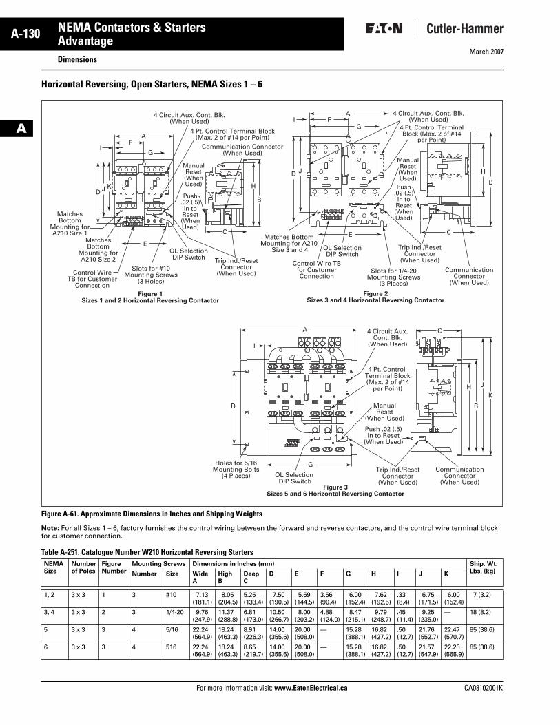
Horizontal Reversing, Open Starters, NEMA Sizes 1 – 6
Figure A-61. Approximate Dimensions in Inches and Shipping Weights
Note: For all Sizes 1 – 6, factory furnishes the control wiring between the forward and reverse contactors, and the control wire terminal block for customer connection.
Table A-251. Catalogue Number W210 Horizontal Reversing Starters NEMA Size
Numberof Poles
FigureNumber
Mounting Screws Dimensions in Inches (mm) Ship. Wt. Lbs. (kg)Number Size Wide
AHighB
DeepC
D E F G H I J K
1, 2 3 x 3 1 3 #10 7.13(181.1)
8.05(204.5)
5.25(133.4)
7.50(190.5)
5.69(144.5)
3.56(90.4)
6.00(152.4)
7.62(192.5)
.33(8.4)
6.75(171.5)
6.00(152.4)
7 (3.2)
3, 4 3 x 3 2 3 1/4-20 9.76(247.9)
11.37(288.8)
6.81(173.0)
10.50(266.7)
8.00(203.2)
4.88(124.0)
8.47(215.1)
9.79(248.7)
.45(11.4)
9.25(235.0)
— 18 (8.2)
5 3 x 3 3 4 5/16 22.24(564.9)
18.24(463.3)
8.91(226.3)
14.00(355.6)
20.00(508.0)
— 15.28 (388.1)
16.82(427.2)
.50(12.7)
21.76(552.7)
22.47(570.7)
85 (38.6)
6 3 x 3 3 4 516 22.24(564.9)
18.24(463.3)
8.65(219.7)
14.00(355.6)
20.00(508.0)
— 15.28(388.1)
16.82(427.2)
.50(12.7)
21.57(547.9)
22.28(565.9)
85 (38.6)
AF
D J K
IG
E
C
B
H
4 Circuit Aux. Cont. Blk.(When Used)
Control WireTB for Customer
Connection
MatchesBottom
Mounting forA210 Size 2
MatchesBottom
Mounting forA210 Size 1
Slots for #10Mounting Screws
(3 Holes)
4 Pt. Control Terminal Block(Max. 2 of #14 per Point)
AF
D J
IG
E C
B
H
4 Circuit Aux. Cont. Blk.(When Used)
Control Wire TBfor CustomerConnection
Matches BottomMounting for A210
Size 3 and 4
Slots for 1/4-20Mounting Screws
(3 Places)
4 Pt. Control TerminalBlock (Max. 2 of #14
per Point)
Figure 1Sizes 1 and 2 Horizontal Reversing Contactor
Figure 2Sizes 3 and 4 Horizontal Reversing Contactor
OL SelectionDIP Switch
OL SelectionDIP Switch
Trip Ind./ResetConnector
(When Used)
Communication Connector(When Used)
CommunicationConnector
(When Used)
ManualReset(WhenUsed)
Trip Ind./ResetConnector
(When Used)
ManualReset(WhenUsed)
Push.02 (.5)in toReset(WhenUsed)
Push.02 (.5)in toReset(WhenUsed)
A C
I
D
G
B
HK
J
4 Circuit Aux.Cont. Blk.
(When Used)
Holes for 5/16Mounting Bolts
(4 Places) OL Selection DIP Switch
4 Pt. Control Terminal Block(Max. 2 of #14
per Point)
ManualReset
(When Used)
Figure 3Sizes 5 and 6 Horizontal Reversing Contactor
Trip Ind./ResetConnector
(When Used)
Push .02 (.5)in to Reset
(When Used)
CommunicationConnector
(When Used)
Tab33.book Page 130 Thursday, February 22, 2007 10:27 AM
March 2007
CA08102001K For more information visit: www.EatonElectrical.ca
A-131NEMA Contactors & Starters
A
AdvantageDimensions
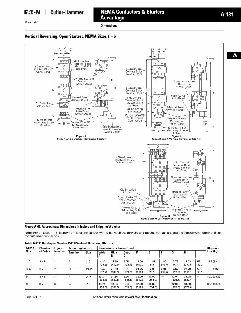
Vertical Reversing, Open Starters, NEMA Sizes 1 – 6
Figure A-62. Approximate Dimensions in Inches and Shipping Weights
Note: For all Sizes 1 – 6, factory furnishes the control wiring between the forward and reverse contactors, and the control wire terminal block for customer connection.
Table A-252. Catalogue Number W250 Vertical Reversing Starters NEMA Size
Numberof Poles
FigureNumber
Mounting Screws Dimensions in Inches (mm) Ship. Wt. Lbs. (kg)Number Size Wide
AHighB
DeepC
D E F G H I
1, 2 3 x 3 1 3 #10 4.27(108.5)
18.50(469.9)
5.25(133.4)
18.00(457.2)
1.88(47.8)
1.80(45.7)
3.73(94.7)
14.72(373.9)
.52(13.2)
7.5 (3.4)
3, 4 3 x 3 2 3 1/4-20 5.42(137.7)
25.13(638.3)
6.81(173.0)
24.25(616.0)
2.88(73.2)
2.31(58.7)
4.62(117.3)
20.28(515.1)
.52(13.2)
19.0 (8.6)
5 3 x 3 3 4 5/16 13.24(336.3)
34.94(887.5)
8.64(219.5)
32.00(812.8)
10.00(254.0)
— 12.04(305.8)
34.78(883.4)
— 85.0 (38.6)
6 3 x 3 3 4 516 13.24(336.3)
34.94(887.5)
8.64(219.5)
32.00(812.8)
10.00(254.0)
— 12.04(305.8)
34.59(878.6)
— 85.0 (38.6)
AG
FI
D
EC
B
H
4 Circuit Aux.Contact Block(When Used)
OL SelectionDIP Switch
Control Wire TBfor CustomerConnection
Push .02 (.5)in to Reset
(When Used)
Slots for #10Mounting Screws
(3 Holes)
4 Pt. Control Terminal Block(Max. 2 of #14
per Point)
Manual Reset(When Used)
CommunicationsConnector
(When Used)
Trip Indication/Reset Connector
(When Used)
CL
AG
FI
D
E C
B
H
4 Circuit Aux.Contact Block(When Used)
4 Circuit Aux.Contact Block(When Used)
Control Wire TBfor CustomerConnection
Slots for 1/4-20Mounting Screws
(3 Places)
4 Pt. Control Terminal Block(Max. 2 of #14
per Point)Manual Reset(When Used)
Trip Ind./ResetConnector
(When Used)
OL SelectionDIP Switch
CommunicationsConnector
(When Used)
Push .02 (.5)in to Reset
Figure 2Sizes 3 and 4 Vertical Reversing Starter
Figure 1Sizes 1 and 2 Vertical Reversing Starter
AG
D
E
BH
4 Circuit Aux.Contact Block(When Used)
Control Wire TBfor CustomerConnection
Holes for 5/16Mounting Bolts
(4 Places)
4 Pt. Control Terminal Block(Max. 2 of #14
per Point)
OL Selection DIP Switch Manual Reset
Push .02 (.5)in to Reset
Trip Ind./ ResetConnector
(When Used)
CommunicationsConnector
(When Used)
C
Figure 3Sizes 5 and 6 Vertical Reversing Starter
Tab33.book Page 131 Thursday, February 22, 2007 10:27 AM
March 2007
A-132
For more information visit: www.EatonElectrical.ca CA08102001K
NEMA Contactors & Starters
A
AdvantageWiring Diagrams
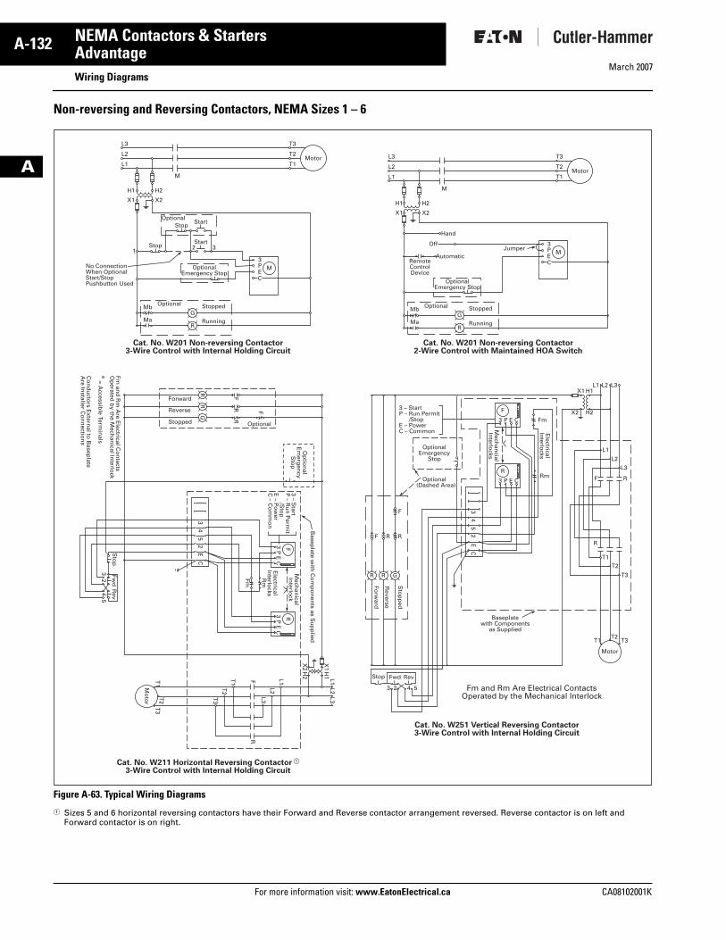
Non-reversing and Reversing Contactors, NEMA Sizes 1 – 6
Figure A-63. Typical Wiring Diagrams
� Sizes 5 and 6 horizontal reversing contactors have their Forward and Reverse contactor arrangement reversed. Reverse contactor is on left and Forward contactor is on right.
L3
L2
L1
T3
T2
T1
H1
X1
132
3M
GMa
Mb
R
PEC
StartStop
StartOptional
Stop
OptionalEmergency Stop
H2
M
Motor
X2
Stopped
No ConnectionWhen OptionalStart/StopPushbutton Used
Optional
Running
Cat. No. W201 Non-reversing Contactor3-Wire Control with Internal Holding Circuit
L3
L2
L1
T3
T2
T1
H1
X1
3M
GMa
Mb
R
PEC
Automatic
H2
M
Motor
X2
StoppedOptional
Running
OptionalEmergency Stop
RemoteControlDevice
JumperOff
Hand
Cat. No. W201 Non-reversing Contactor2-Wire Control with Maintained HOA Switch
Cat. No. W211 Horizontal Reversing Contactor �
3-Wire Control with Internal Holding Circuit
Cat. No. W251 Vertical Reversing Contactor3-Wire Control with Internal Holding Circuit
Fm and Rm Are Electrical ContactsOperated by the Mechanical Interlock
T1
T3
T2
Mo
tor
T2
T3
T1
Sto
pFw
dR
ev
32
54
Stop Fwd Rev
3 2 54
F
F
FR
R
RR
G
F
3P
EC
3P
EC
R
R
L1 L1X
1H
1
X2
H2
L2 L2
L3 L3
Mech
anical
Interlo
ck
Basep
late with
Co
mp
on
ents as S
up
plied
Electrical
Interlo
cksR
m
Fm
3 – Start
P – R
un
Perm
it /S
top
E – P
ow
erC
– Co
mm
on
Op
tion
alE
merg
ency
Sto
p
43
CE
52
43
CE
52
Optional
Forward
Reverse
Stopped
Fm an
d R
m A
re Electrical C
on
tactsO
perated
by th
e Mech
anical In
terlock
= Accessib
le Termin
als
Co
nd
ucto
rs Extern
al to B
aseplate
Are In
staller Co
nn
ection
s
Fm
Rm
Mech
ancial
Interlo
cks
Electrical
Interlo
cks
R
3 P E C
F
Sto
pp
ed
Reverse
Forw
ard
3 P E C
R
F
RRF
T1 T3T2
Motor
T2
T3
T1
R
F R
L1
L1X1 H1
X2 H2
L2
L2
L3
L3
3 – StartP – Run Permit /StopE – PowerC – Common
OptionalEmergency
Stop
Optional (Dashed Area)
R G
Baseplatewith Components
as Supplied
Tab33.book Page 132 Thursday, February 22, 2007 10:27 AM
March 2007
CA08102001K For more information visit: www.EatonElectrical.ca
A-133NEMA Contactors & Starters
A
AdvantageWiring Diagrams
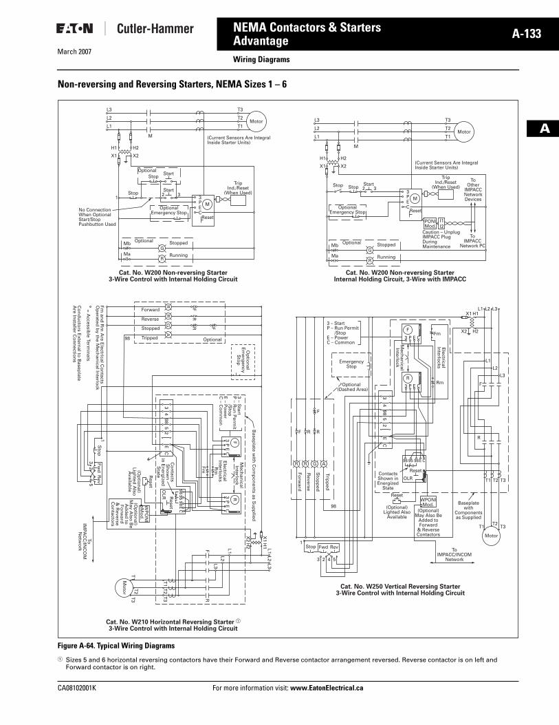
Non-reversing and Reversing Starters, NEMA Sizes 1 – 6
Figure A-64. Typical Wiring Diagrams
� Sizes 5 and 6 horizontal reversing contactors have their Forward and Reverse contactor arrangement reversed. Reverse contactor is on left and Forward contactor is on right.
L3
L2
L1
T3
T2
T1
H1
X1
132
3M
GMa
Mb
R
Reset
TripInd./Reset
(When Used)
PEC
StartStop
StartOptional
Stop
OptionalEmergency Stop
H2
M
Motor
X2
(Current Sensors Are IntegralInside Starter Units)
Stopped
No ConnectionWhen OptionalStart/StopPushbutton Used
Optional
Running
Start2 3StopStop
Cat. No. W200 Non-reversing Starter3-Wire Control with Internal Holding Circuit
L3
L2
L1
T3
T2
T1
H1
X1
3M
PONIMod.
GMa
Mb
R
Reset
TripInd./Reset
(When Used)To
OtherIMPACCNetworkDevices
ToIMPACC
Network PC
PEC
H2
M
Motor
X2(Current Sensors Are IntegralInside Starter Units)
Caution – UnplugIMPACC PlugDuringMaintenanceStoppedOptional
Running
I1I2
OptionalEmergency Stop
Cat. No. W200 Non-reversing StarterInternal Holding Circuit, 3-Wire with IMPACC
Cat. No. W210 Horizontal Reversing Starter �
3-Wire Control with Internal Holding Circuit
Cat. No. W250 Vertical Reversing Starter3-Wire Control with Internal Holding Circuit
T1
T3
T2
Mo
tor
T2
T3
T1
Sto
p
Reset
Reset
Fwd
Rev
ToIM
PAC
C/IN
CO
MN
etwo
rk
3
1
24
5
Stop Fwd Rev
3 2 4 5
(Op
tion
al)Lig
hted
Also
Availab
le(O
ptio
nal)
May A
lso B
eA
dd
ed to
Forw
ard&
Reverse
Co
ntacto
rs
WP
ON
IM
od
.
F
F
FR
R
RR
GA
F
3P
EC
3P
EC
R
R
L1 L1X
1H
1
X2
H2
L2 L2
L3 L3
Mech
anical
Interlo
ck
Basep
late with
Co
mp
on
ents as S
up
plied
Electrical
Interlo
cksR
m
Fm
Mech
anical
Interlo
ck
Electrical
Interlo
cks
3 – Start
P – R
un
Perm
it /S
top
E – P
ow
erC
– Co
mm
on
Op
tion
alE
merg
ency
Sto
p
9695
98
984
35
CE
2
984
3C
E5
2
EC
OLR
Optional98
Forward
Reverse
Stopped
Tripped
Fm an
d R
m A
re Electrical C
on
tactsO
perated
by th
e Mech
anical In
terlock
= A
ccessible Term
inals
Co
nd
ucto
rs Extern
al to B
aseplate
Are In
staller Co
nn
ection
s
Co
ntacts
Sh
ow
nin
En
ergized
State
Reset
98
1
Reset
ToIMPACC/INCOM
Network
(Optional)Lighted Also
Available(Optional)
May Also BeAdded toForward
& ReverseContactors
WPONIMod.
96 95 98E C
OLRContactsShown inEnergized
State
R
3 PFm
EmergencyStop
Rm
E C
F
3 P E C
R
T1 T3T2
Motor
T2 T3T1
R
F
L1
L1X1 H1
X2 H2
L2
L2
L3
L3
3 – StartP – Run Permit /StopE – PowerC – Common
G A
Baseplatewith
Componentsas Supplied
Tripp
ed
Sto
pp
ed
Forw
ard
F
R
R
Reverse
RF
Optional (Dashed Area)
Tab33.book Page 133 Thursday, February 22, 2007 10:27 AM
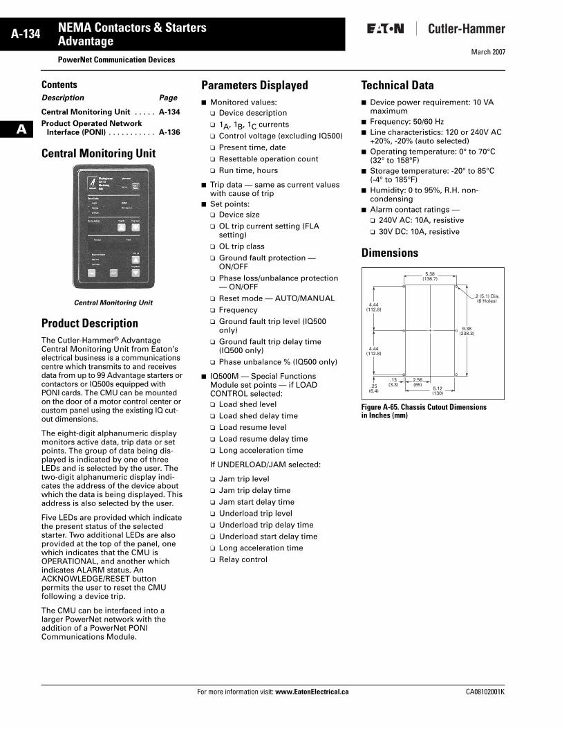
March 2007
A-134
For more information visit: www.EatonElectrical.ca CA08102001K
NEMA Contactors & Starters
A
AdvantagePowerNet Communication Devices
ContentsDescription Page
Central Monitoring Unit . . . . . A-134
Product Operated NetworkInterface (PONI) . . . . . . . . . . . A-136
Central Monitoring Unit
Central Monitoring Unit
Product DescriptionThe Cutler-Hammer® Advantage Central Monitoring Unit from Eaton’s electrical business is a communications centre which transmits to and receives data from up to 99 Advantage starters or contactors or IQ500s equipped with PONI cards. The CMU can be mounted on the door of a motor control center or custom panel using the existing IQ cut-out dimensions.
The eight-digit alphanumeric display monitors active data, trip data or set points. The group of data being dis-played is indicated by one of three LEDs and is selected by the user. The two-digit alphanumeric display indi-cates the address of the device about which the data is being displayed. This address is also selected by the user.
Five LEDs are provided which indicate the present status of the selected starter. Two additional LEDs are also provided at the top of the panel, one which indicates that the CMU is OPERATIONAL, and another which indicates ALARM status. An ACKNOWLEDGE/RESET button permits the user to reset the CMUfollowing a device trip.
The CMU can be interfaced into a larger PowerNet network with the addition of a PowerNet PONI Communications Module.
Parameters Displayed� Monitored values:
❑ Device description❑ 1A, 1B, 1C currents❑ Control voltage (excluding IQ500)❑ Present time, date❑ Resettable operation count❑ Run time, hours
� Trip data — same as current values with cause of trip
� Set points:❑ Device size❑ OL trip current setting (FLA
setting)❑ OL trip class❑ Ground fault protection —
ON/OFF❑ Phase loss/unbalance protection
— ON/OFF❑ Reset mode — AUTO/MANUAL❑ Frequency❑ Ground fault trip level (IQ500
only)❑ Ground fault trip delay time
(IQ500 only)❑ Phase unbalance % (IQ500 only)
� IQ500M — Special Functions Module set points — if LOAD CONTROL selected:❑ Load shed level❑ Load shed delay time❑ Load resume level❑ Load resume delay time❑ Long acceleration time
If UNDERLOAD/JAM selected:
❑ Jam trip level❑ Jam trip delay time❑ Jam start delay time❑ Underload trip level❑ Underload trip delay time❑ Underload start delay time❑ Long acceleration time❑ Relay control
Technical Data� Device power requirement: 10 VA
maximum� Frequency: 50/60 Hz� Line characteristics: 120 or 240V AC
+20%, -20% (auto selected)� Operating temperature: 0° to 70°C
(32° to 158°F)� Storage temperature: -20° to 85°C
(-4° to 185°F)� Humidity: 0 to 95%, R.H. non-
condensing� Alarm contact ratings —
❑ 240V AC: 10A, resistive❑ 30V DC: 10A, resistive
Dimensions
Figure A-65. Chassis Cutout Dimensionsin Inches (mm)
9.38(238.3)
4.44(112.8)
4.44(112.8)
.25(6.4)
2.56(65)
.13(3.3)
5.12(130)
5.38(136.7)
.2 (5.1) Dia.(6 Holes)
Tab33.book Page 134 Thursday, February 22, 2007 10:27 AM
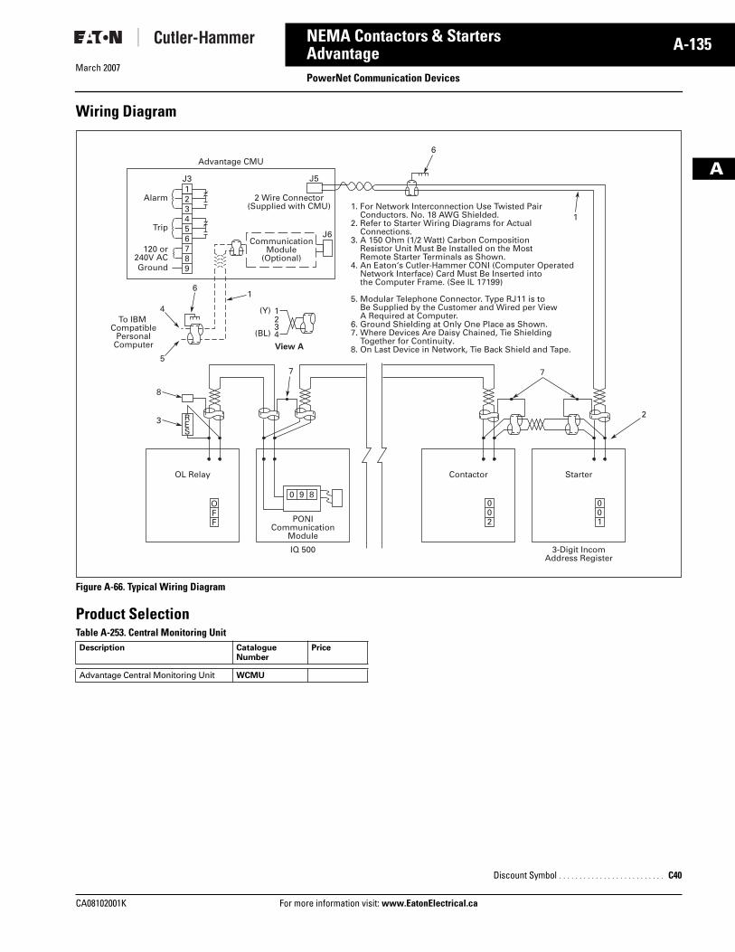
March 2007
CA08102001K For more information visit: www.EatonElectrical.ca
A-135NEMA Contactors & Starters
A
AdvantagePowerNet Communication Devices
Wiring Diagram
Figure A-66. Typical Wiring Diagram
Product SelectionTable A-253. Central Monitoring Unit Description Catalogue
NumberPrice
Advantage Central Monitoring Unit WCMU
1. For Network Interconnection Use Twisted Pair Conductors. No. 18 AWG Shielded.2. Refer to Starter Wiring Diagrams for Actual Connections.3. A 150 Ohm (1/2 Watt) Carbon Composition Resistor Unit Must Be Installed on the Most Remote Starter Terminals as Shown.4. An Eaton‘s Cutler-Hammer CONI (Computer Operated Network Interface) Card Must Be Inserted into the Computer Frame. (See IL 17199)
5. Modular Telephone Connector. Type RJ11 is to Be Supplied by the Customer and Wired per View A Required at Computer.6. Ground Shielding at Only One Place as Shown.7. Where Devices Are Daisy Chained, Tie Shielding Together for Continuity.8. On Last Device in Network, Tie Back Shield and Tape.
Advantage CMU
Alarm
Trip
Ground
120 or240V AC
J5
J6
2 Wire Connector(Supplied with CMU)
CommunicationModule
(Optional)
To IBM Compatible
PersonalComputer
1J3
1
1
23
3
4
12
2
34
5
4
6
5
6
6
7
7 7
8
8
9
(Y)
(BL)
View A
OL Relay
PONICommunication
Module
IQ 500 3-Digit IncomAddress Register
Contactor Starter
RES
OFF
0 9 8002
001
Discount Symbol . . . . . . . . . . . . . . . . . . . . . . . . . . C40
Tab33.book Page 135 Thursday, February 22, 2007 10:27 AM
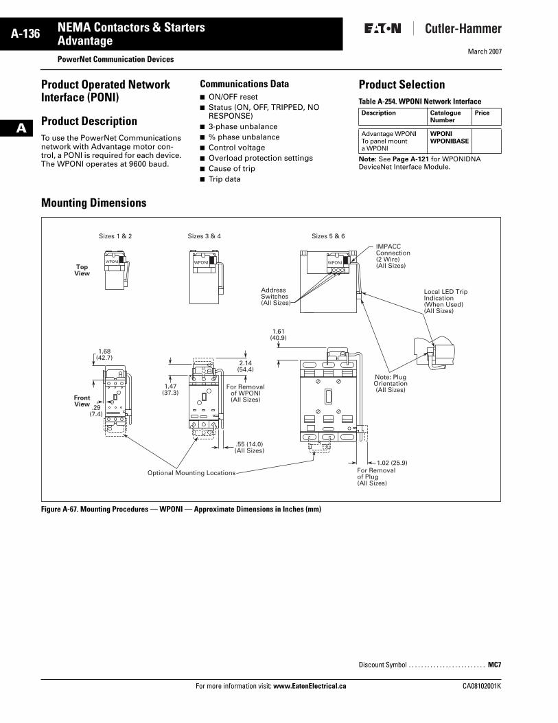
March 2007
A-136
For more information visit: www.EatonElectrical.ca CA08102001K
NEMA Contactors & Starters
A
AdvantagePowerNet Communication Devices
Product Operated Network Interface (PONI)
Product DescriptionTo use the PowerNet Communications network with Advantage motor con-trol, a PONI is required for each device. The WPONI operates at 9600 baud.
Communications Data� ON/OFF reset� Status (ON, OFF, TRIPPED, NO
RESPONSE)� 3-phase unbalance� % phase unbalance� Control voltage� Overload protection settings� Cause of trip� Trip data
Product SelectionTable A-254. WPONI Network Interface
Note: See Page A-121 for WPONIDNA DeviceNet Interface Module.
Mounting Dimensions
Figure A-67. Mounting Procedures — WPONI — Approximate Dimensions in Inches (mm)
Description Catalogue Number
Price
Advantage WPONITo panel mount a WPONI
WPONIWPONIBASE
Sizes 1 & 2 Sizes 3 & 4 Sizes 5 & 6
1.68(42.7)
1.47(37.3)
2.14(54.4)
1.61(40.9)
.29(7.4)
1.02 (25.9)For Removalof Plug(All Sizes)
For Removalof WPONI(All Sizes)
.55 (14.0)(All Sizes)
Optional Mounting Locations
Local LED TripIndication(When Used)(All Sizes)
IMPACCConnection(2 Wire)(All Sizes)
Note: PlugOrientation(All Sizes)
TopView
FrontView
AddressSwitches(All Sizes)
WPONIWPONIWPONI
Discount Symbol . . . . . . . . . . . . . . . . . . . . . . . . . MC7
Tab33.book Page 136 Thursday, February 22, 2007 10:27 AM


![33-36 NEMA Contactors & Starters Thermal Overload Relays … · 2017-07-13 · NEMA Contactors & Starters 33 Thermal Overload Relays Freedom Line Vol. 2, Ref. No. [0050] Technical](https://img.pdfslide.us/doc/110x75/5e914b6b3f90271d1b711acd/33-36-nema-contactors-starters-thermal-overload-relays-2017-07-13-nema-contactors.jpg)


![Cutler-Hammer NEMA Contactors & Starters Thermal ... January 2001 Vol. 2, Ref. No. 10053] NEMA Contactors & Starters Thermal Overload Relays Freedom Line 33-37 Table 33-74. Standard](https://img.pdfslide.us/doc/110x75/5ac0a7ec7f8b9a213f8c3cf8/cutler-hammer-nema-contactors-starters-thermal-january-2001-vol-2-ref-no.jpg)
![NEMA Contactors & Starters Cutler-Hammer · 33-40 NEMA Contactors & Starters 3-Phase Magnetic Starters — Enclosed Freedom Line Cutler-Hammer January 2001 Vol. 2, Ref. No. [0056]](https://img.pdfslide.us/doc/110x75/5b93b9bd09d3f22b0a8bdaac/nema-contactors-starters-cutler-33-40-nema-contactors-starters-3-phase.jpg)