Embed Size (px)
Citation preview

56 CHAPTER 9X. ADVANCED TOPICS IN POWER CONTROL
9x.19 PWM for DC Motors
Those of us who grew up with electric train sets remember well the difficulty in controlling theirspeed: the train is stationary; you gradually advance the control knob or level, but the train stub-bornly sits there, then a moment later it rushes off. In those days the same recalcitrance afflictedsewing machines, with their pedal-operated speed control. It was a wonder anyone could controlthose things. But now you can get tools with speed controls that actually work – battery-powereddrills, for example, where the speed is well-controlled as you advance the trigger, in spite of largevariations of mechanical load as you drill your way through tough material.
9x.19.1 The Myth: PWM as Secret Sauce
These latter tools use permanent-magnet (PM) dc motors, with pulse-width modulation of thebattery’s dc voltage. They deliver plenty of torque at low speed, in contrast to the sewing machinesand train sets of yesteryear. So it’s easy to conclude (incorrectly, as we’ll see) that it’s the magic ofPWM that delivers the desirable feature of well-controlled speed with adequate torque. To elaborateon this thinking, you might imagine that the pulsed current delivers high peak torque, with themotor gliding between pulses, and thus that PWM is more effective than the alternative of applyinga steady dc voltage equal to the average PWM voltage (i.e., peak voltage times duty-cycle). Thishas caused considerable confusion, with statements like this: “Controlling the speed of somethinglike a DC motor by varying the voltage (even in an efficient way) is a poor technique. It limits themotor to low torque at lower speeds because of limited power. That is why it is more common to seePWM (Pulse-Width Modulation) used to control motors (and lights/LEDs as well). PWM allowsmotors to have more torque at low speeds.”
Such thinking would suggest that PWM is superior to applying a variable dc voltage, and that theexperience with trains and sewing machines provides confirmation.
A. An Experiment
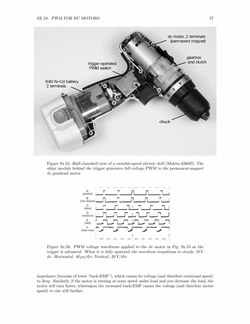
With characteristic arrogance, we decided to get to the bottom of this. First step, echoing eevblog’sDave Jones (“Don’t turn it on, Take it apart!”), was a look at the innards of a typical battery-powered drill (Fig. 9x.55). Not much there – in particular there is no tachometer or other rotational-speed feedback, just PWM to a 2-terminal dc motor. Figure 9x.56 shows the voltage waveforms atincreasing degrees of trigger depression.
Now for the fun: we intercepted the motor leads and applied dc from an external power supply.We did this to test the proposition that PWM is “better” than steady dc in terms of torque at lowspeed. We used a big drill bit to bore into hunks of plywood (Fig. 9x.57) at low speed, comparingthe drill’s muscle with both PWM and dc drive. And we found. . . (drumroll). . . that there was nodiscernible difference!
B. Toy Trains and Sewing Machines
But this disagrees with our childhood “knowledge.” What’s going on? It turns out that thosecontrollers of yesteryear did not provide a variable (and stiff) voltage source – instead they useda fixed voltage (either dc or ac) in series with a variable impedance (a rheostat, fancy name for awirewound potentiometer that can dissipate at least a few watts). If you think about it, this is aterrible way to control a motor: Imagine you’ve set the rheostat so the motor’s turning slowly, andthen you increase the mechanical load on the motor; the latter then slows down, presenting a lower
9X.19. PWM FOR DC MOTORS 57
Figure 9x.55: Half-clamshell view of a variable-speed electric drill (Makita 6260D). Theshiny module behind the trigger generates full-voltage PWM to the permanent-magnetdc gearhead motor.
A.(stalled)
B.(min speed)
C.(slow)
D.(medium)
E.(fast)
F.(near max)
Figure 9x.56: PWM voltage waveforms applied to the dc motor in Fig. 9x.55 as thetrigger is advanced. When it is fully squeezed the waveform transitions to steady 10Vdc. Horizontal: 40 µs/div; Vertical: 20V/div.
impedance (because of lower “back-EMF”), which causes its voltage (and therefore rotational speed)to drop. Similarly, if the motor is turning at some speed under load and you decrease the load, themotor will turn faster, whereupon the increased back-EMF causes the voltage (and therefore motorspeed) to rise still further.
58 CHAPTER 9X. ADVANCED TOPICS IN POWER CONTROL
Figure 9x.57: Victimized plywood, following drill-torque tests.
C. Another Experiment
To compare the merits of voltage-drive with what we might call rheostat-drive, we rigged up twoexperiments, each of which let us see the ramp-up of a dc motor when driven either with a fixed lowvoltage (i.e., less than the motor’s rated voltage), or with a series resistor from a higher voltage, theresistor chosen to produce the same lower motor voltage once things had stabilized. The ramp-upfrom a cold start is a simple proxy for torque, and it’s easier to measure.
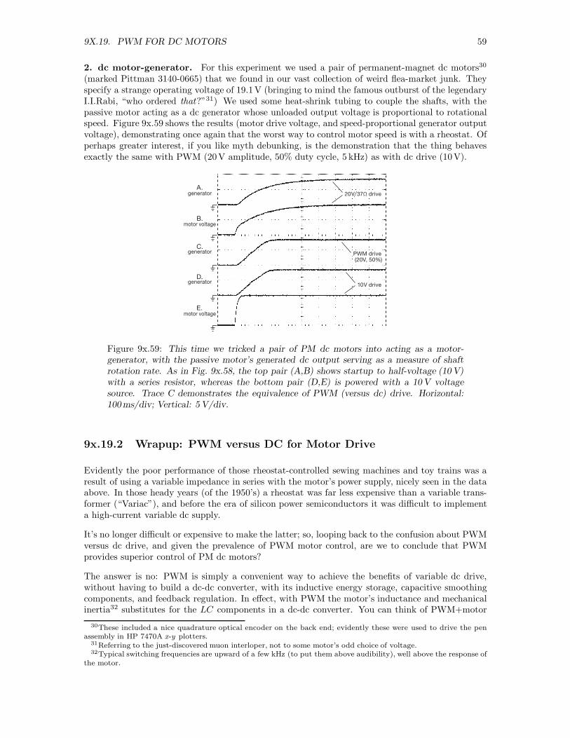
1. dc fan with tachometer. For this experiment we used a 120mm 12V brushless cooling fan(Delta AFB1212SH); it has a logic-level tachometer output that generates two pulses per revolution.We ran it at half voltage (6 V), using either a 6 V dc supply, or a 12V supply with a 24 Ω seriesresistor (the value that produced 6 V across the fan after settling to its final speed). Figure 9x.58shows the results (both fan voltage and tachometer pulses) when ramping up from a cold start. It’sclear that a series resistor causes considerably reduced torque (slower ramp-up of both voltage andspeed), as just explained in §9x.19.1B.
(10V/div)tachometer
6V
dri
ve
12
V/2
4Ω
dri
ve
(5V/div)fan voltage
(10V/div)tachometer
(5V/div)fan voltage
A.
B.
C.
D.
Figure 9x.58: Tachometer output (A, C) and fan voltage (B, D) for a 12 V dc fan, asmeasured from a cold start for two configurations that run the fan at half voltage (6V):The top pair used a 12 V supply with 24 Ω series resistor; the bottom pair used a 6 Vsupply and no resistor. Horizontal: 100ms/div.
9X.19. PWM FOR DC MOTORS 59
2. dc motor-generator. For this experiment we used a pair of permanent-magnet dc motors30
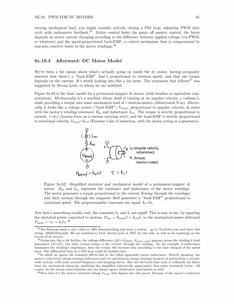
(marked Pittman 3140-0665) that we found in our vast collection of weird flea-market junk. Theyspecify a strange operating voltage of 19.1V (bringing to mind the famous outburst of the legendaryI.I.Rabi, “who ordered that?”31) We used some heat-shrink tubing to couple the shafts, with thepassive motor acting as a dc generator whose unloaded output voltage is proportional to rotationalspeed. Figure 9x.59 shows the results (motor drive voltage, and speed-proportional generator outputvoltage), demonstrating once again that the worst way to control motor speed is with a rheostat. Ofperhaps greater interest, if you like myth debunking, is the demonstration that the thing behavesexactly the same with PWM (20V amplitude, 50% duty cycle, 5 kHz) as with dc drive (10V).
generator
generator10V drive
PWM drive (20V, 50%)
20V/37Ω drive
motor voltage
motor voltage
A.
B.
D.
generatorC.
E.
Figure 9x.59: This time we tricked a pair of PM dc motors into acting as a motor-generator, with the passive motor’s generated dc output serving as a measure of shaftrotation rate. As in Fig. 9x.58, the top pair (A,B) shows startup to half-voltage (10 V)with a series resistor, whereas the bottom pair (D,E) is powered with a 10 V voltagesource. Trace C demonstrates the equivalence of PWM (versus dc) drive. Horizontal:100ms/div; Vertical: 5 V/div.
9x.19.2 Wrapup: PWM versus DC for Motor Drive
Evidently the poor performance of those rheostat-controlled sewing machines and toy trains was aresult of using a variable impedance in series with the motor’s power supply, nicely seen in the dataabove. In those heady years (of the 1950’s) a rheostat was far less expensive than a variable trans-former (“Variac”), and before the era of silicon power semiconductors it was difficult to implementa high-current variable dc supply.
It’s no longer difficult or expensive to make the latter; so, looping back to the confusion about PWMversus dc drive, and given the prevalence of PWM motor control, are we to conclude that PWMprovides superior control of PM dc motors?
The answer is no: PWM is simply a convenient way to achieve the benefits of variable dc drive,without having to build a dc-dc converter, with its inductive energy storage, capacitive smoothingcomponents, and feedback regulation. In effect, with PWM the motor’s inductance and mechanicalinertia32 substitutes for the LC components in a dc-dc converter. You can think of PWM+motor
30These included a nice quadrature optical encoder on the back end; evidently these were used to drive the penassembly in HP 7470A x-y plotters.
31Referring to the just-discovered muon interloper, not to some motor’s odd choice of voltage.32Typical switching frequencies are upward of a few kHz (to put them above audibility), well above the response of
the motor.

60 CHAPTER 9X. ADVANCED TOPICS IN POWER CONTROL
Figure 9x.60: A vintage sewing-machine pedal-operated rheostat-type control. Thisthing gets hot, so the power resistor is kept safely inside a well-ventilated cage.
Figure 9x.61: Vintage Lionel model 81 train-set rheostat. The handle moves a slidingcontact along the wirewound power resistor inside the ventilated enclosure.
as comprising a buck converter, equivalent to a dc voltage equal to the switched voltage times theswitching duty cycle.33 So all that’s needed is a PWM switching signal to drive a MOSFET, witha catch diode (or MOSFET) to complete the motor drive. Easy peasy.
Looking slightly deeper, there are some disadvantages to PWM (compared with dc), namely thehigh switching frequency (and its harmonics) generates additional losses in the magnetic materials,and there are dynamic switching losses associated with switch and parasitic capacitances (“hardswitching”). Overall, however, PWM is easy, and efficient enough to make it the technique of choicein dc motor control.34
One might add, as an afterthought, that if your goal is to tightly control a motor’s rpm over
33And, as with a buck converter, the current out of the motor’s return lead is dc, with little ripple.34And in some cases the pulsating torque caused by PWM can be beneficial, particularly at low speeds where it
can overcome “stiction” and “cogging.”
9X.19. PWM FOR DC MOTORS 61
varying mechanical load, you might consider actively closing a PID loop, adjusting PWM dutycycle with tachometer feedback.35 Active control beats the pants off passive control; the latterdepends on motor current changing according to the difference between applied voltage (via PWM,or whatever) and the speed-proportional back-EMF, a control mechanism that is compromised bynon-zero resistive losses in the motor windings.36
9x.19.3 Afterward: DC Motor Model
We’ve been a bit casual about what’s actually going on inside the dc motor, having arrogantlyasserted that there’s a “back-EMF” that’s proportional to rotation speed, and that the torquedepends on the current. It’s worth looking into this a bit more. The treatment that follows37 wassuggested by Steven Leeb, to whom we are indebted.
Figure 9x.62 is the basic model for a permanent-magnet dc motor (with brushes or equivalent com-mutation). Mechanically it’s a machine whose shaft is turning at an angular velocity ω radians/s,while providing a torque into some mechanical load of τ newton-meters (abbreviated N·m). Electri-
cally it looks like a voltage source (“back-EMF”) Vbemf , proportional to angular velocity, in serieswith the motor’s winding resistance Rm and inductance Lm. The torque is strictly proportional tocurrent, τ=kiI (Lorenz force on a current-carrying wire), and the back-EMF is strictly proportionalto rotational velocity, Vbemf=kvω (Faraday’s law of induction, with the motor acting as a generator).
Figure 9x.62: Simplified electrical and mechanical model of a permanent-magnet dcmotor. Rm and Lm represent the resistance and inductance of the motor windings.The motor generates a torque proportional to the current flowing through the windings;and their motion through the magnetic field generates a “back-EMF” proportional torotational speed. The proportionality constants are equal: kv=ki.
Now here’s something totally cool: the constants kv and ki are equal! This is easy to see, by equatingthe electrical power converted to motion, Pelec = VbemfI = kvωI, to the mechanical power deliveredPmech = τω = kiIω.38
35Jim Roberge made a nice video in 1985 demonstrating just such a system – go to YouTube.com and enter thisstring: uHtKGf4AymM. We are indebted to Prof. Steven Leeb at MIT for this link, as well as for teachings on thesecrets of dc motors.
36Going into this a bit further, the voltage difference (∆V =VPWM−Vback−emf) appears across the winding’s totalimpedance (R+jX), but what creates torque is the current through the winding. So, for example, if inductancedominates the winding’s impedance, then the torque will increase only according to the time integral of the speederror. The differential term in a PID loop could do wonders here.
37In which we ignore the transient effects due to the (often ignorable) motor inductance. Strictly speaking, themotor’s (electrical, energy-storing) inductance and its (mechanical, energy-storing) moment of inertia form a second-order system, with some natural frequency and damping factor. But the electrical time scale is ordinarily far fasterthan the mechanical timescale, justifying the simplified (electrically quasi-static) first-order treatment below. Ofcourse, for the steady-state behavior one can always ignore inductance (and inertia as well).
38Note that it’s the motor’s internal voltage Vbemf that figures into this proof. Because of the motor’s resistance

62 CHAPTER 9X. ADVANCED TOPICS IN POWER CONTROL
Now to the business of dc (or PWM) drive versus rheostat drive. Looking first at the limitingcases, for a perfect current source drive (i.e., of unlimited voltage compliance) the motor simplyproduces constant torque. With no mechanical load it will accelerate without limit, and the terminalvoltage will track the angular speed. With a mechanical load whose torque is proportional to speed(say τ=βω, a viscous drag) the motor will accelerate until the load’s torque matches the motor’scurrent-determined torque: ωfinal=kI/β. And if the “coefficient of viscosity” β changes, so will theequilibrium speed. It’s rubbery – it behaves like the hard-to-control sewing machine.
At the other limit (a voltage source), the motor’s steady-state velocity is simply ωfinal=V/k, thespeed at which the back-EMF equals the applied voltage. For a lossless motor (Rm=0) that speedis independent of load torque – any attempt to lower the speed by increasing the load causes amismatch of drive voltage and back-EMF, and is thus met with an enormous current (the voltagemismatch across Rm=0) that maintains the speed.39
For the realistic case of finite (but small) Rm, the acceleration to final speed is finite; and loading themotor with mechanical torque causes some degree of slowing, because the current required to producethe torque creates some voltage drop across Rm, thus leaving somewhat less voltage to balance theback-EMF. But the motor fights the slowdown: the reduced back-EMF puts more voltage acrossRm, thus more current (and more torque). The lower Rm, the more effective the motor is in runningat a load-independent constant speed.
For the in-between case (driving the motor with a rheostat in series with a dc voltage), the situationis also in-between. Rather than hand-waving, let’s put this more quantitatively. Figure 9x.63 showsthe arrangement, where we’ve ignored the (small) winding impedance; i.e., an ideal lossless motor.For a given supply voltage Vs and rheostat setting Rs, the motor current (for rotation speed ω) isjust
I =Vs − Vbemf
Rs
=Vs − kω
Rs
, (9x.1)
producing a motor torque
τ = kI =k
Rs
(Vs − kω) =kVs
Rs
−k2ω
Rs
. (9x.2)
Figure 9x.63: A fixed dc supply powers an ideal dc motor, with (undesirable) speedcontrol through a rheostat (variable resistor).
Equation 9x.2 lets us plot a family of curves of torque versus angular speed (Fig. 9x.64A). Theseshow that the unloaded speed is just ω=Vs/k, the speed at which the back-EMF plus resistive dropequals the supply voltage. Since there’s no load, it’s insensitive to series resistance (though in realitythe motor itself has some bearing and air friction). These curves also show that the starting torque(ω=0) increases inversely with series resistance.
Rm, the voltage you supply to run the motor (call it Vs) is greater than Vbemf , unless you have an “ideal motor”

9X.19. PWM FOR DC MOTORS 63
Figure 9x.64: A. Operating characteristic (load line) for the circuit of Fig. 9x.63, accord-ing to eq’n 9x.2. B. Determining operating points for a linear load cursed with somestiction.
From these operating curves (analogous to load lines, see Appendix F in the main volume) it’s easyto figure out how a loaded motor will behave, by overlaying a curve representing the mechanicalload’s torque versus angular speed (Fig. 9x.64B). Here we’ve drawn a viscous load (τ ∝ ω) that issticky at rest and requires a minimum torque to overcome its “stiction” (static friction). For themotor to start with that load you must have Rs < kVs/τstiction: a graphical representation of theannoying “deadband” affliction of those rheostat controllers of yesteryear.
the bottom line: for good control of motor speed in situations of varying mechanical loading,power your dc motors from a low-impedance voltage source, adjusting the voltage to set the rotationspeed. Equivalently, you can use pulse-width modulation to control motor speed, starting from avoltage source that runs the motor at maximum rated speed for 100% duty cycle. And for theultimate control, use tachometer feedback.
A. Series Resistance: Op-amp Analogy
Here’s another way40 to think about this business of series resistance. Look at Figure 9x.65. Weapply a supply voltage Vs to the (non-ideal) motor, creating a current I that produces a torque τ=kI.
(Rm=0). But kv=ki, regardless.39And, in that unrealistic case of Rm=0, the motor draws infinite current initially, producing infinite acceleration
until reaching final speed.40Steven Leeb, again!

64 CHAPTER 9X. ADVANCED TOPICS IN POWER CONTROL
But the current is proportional to Vs−Vbemf and inversely proportional to Rm: I=(Vs−kω)/Rm.That is, you can think of the motor as a differential amplifier that converts the difference voltage∆V =Vs−Vbemf to torque, with gain (τ/∆V ) equal to k/Rm.
Viewed this way, a good motor has high gain (k/Rm), just as a good op-amp has high open-loop gainGOL. And it doesn’t matter if the resistance comes from the motor or an external series resistanceRs, which simply adds to the motor’s internal resistance for a final (even lower) gain of k/Rtotal.
Finally, closing the loop around the “amplifier” gives us the circuit of Figure 9x.66. The inner (me-chanical) loop includes a proportional (“viscous”) torque drag, plus rotor inertia (which integratesnet torque to spin up the angular speed); the outer loop is the by-now familiar voltage-to-torquecharacteristic of the motor, including the effect of its internal resistance and any external seriesresistance that is foolishly added. Don’t add the latter!
Figure 9x.65: Motor model, viewed as a gain block that converts the voltage differenceVs−kω to a torque τ , with a “gain” of k/Rm.
Figure 9x.66: Closing the loop around the motor-as-amplifier. The inner loop is themechanical system (viscous load torque proportional to speed, plus rotor inertia) thatconverts torque to angular speed; the outer loop takes it from there.