Embed Size (px)
Citation preview
9th Generation Plasma Display
Technical Information1
The technicians have express their needs and we listened.
This presentation has been developed especially for the technicians involved in the repair of our plasma televisions.
We’ve gathered and analyzed your emails, questions, feedback, and requests. Based on this information, we have put together a presentation to fulfill your needs.
2
Topics
• Power Supply/System Control Interaction
• Boards Isolation
• Understanding SOS Condition
• Video Processing
• Troubleshooting
3
9th Generation Plasma Display Television
• What really happens when the TV is plugged in?
4
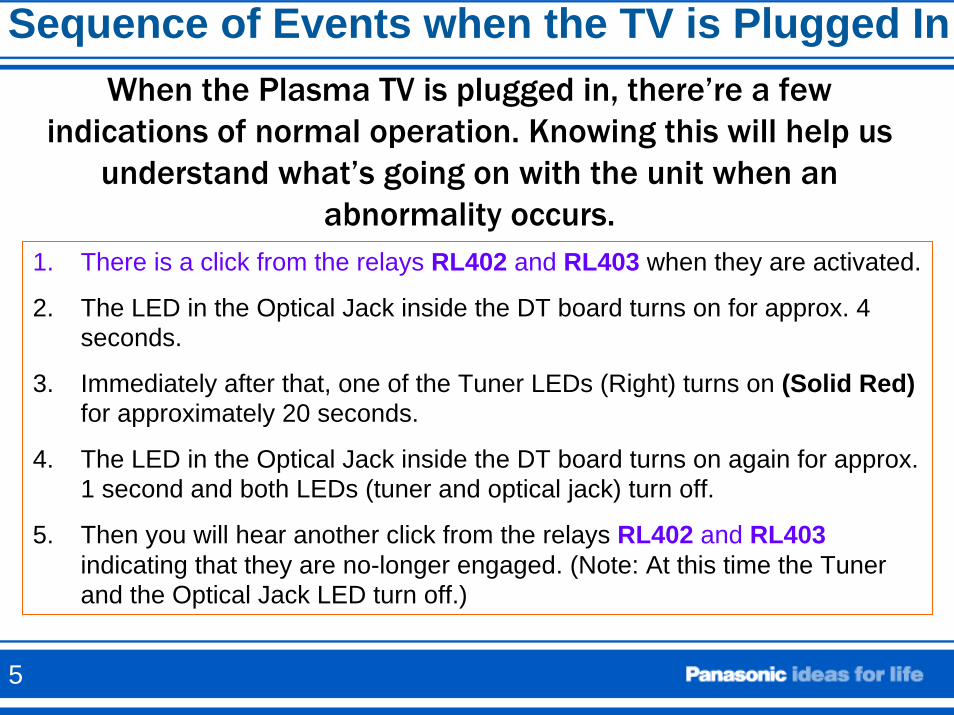
Sequence of Events when the TV is Plugged InWhen the Plasma TV is plugged in, there’re a few
indications of normal operation. Knowing this will help us understand what’s going on with the unit when an
abnormality occurs.1. There is a click from the relays RL402 and RL403 when they are activated.
2. The LED in the Optical Jack inside the DT board turns on for approx. 4 seconds.
3. Immediately after that, one of the Tuner LEDs (Right) turns on (Solid Red)for approximately 20 seconds.
4. The LED in the Optical Jack inside the DT board turns on again for approx. 1 second and both LEDs (tuner and optical jack) turn off.
5. Then you will hear another click from the relays RL402 and RL403 indicating that they are no-longer engaged. (Note: At this time the Tuner and the Optical Jack LED turn off.)
5
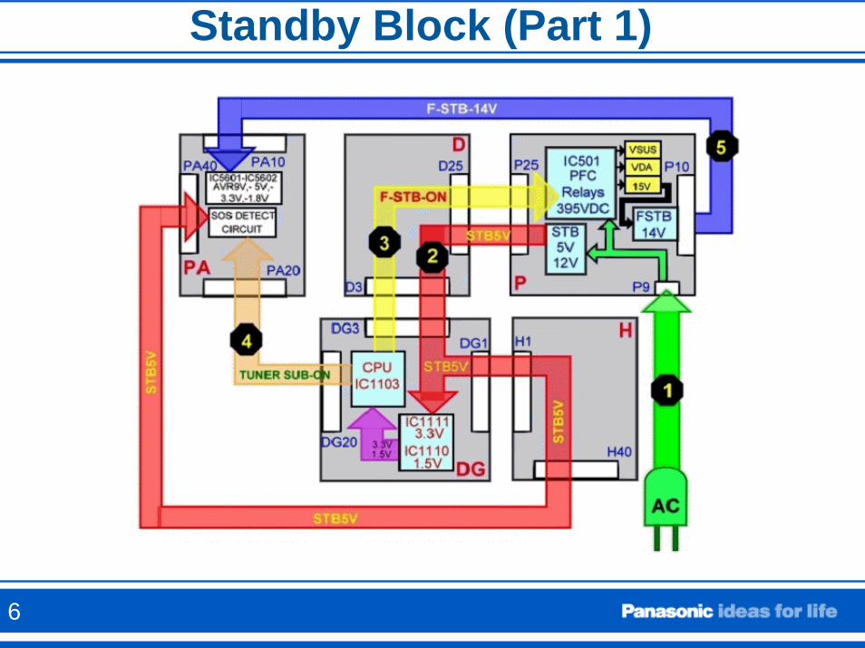
Standby Block (Part 1)
6
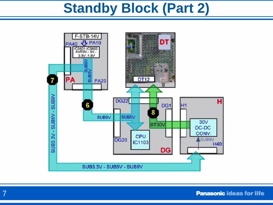
Standby Block (Part 2)
7
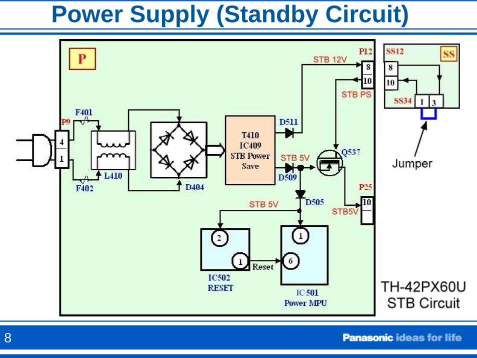
Power Supply (Standby Circuit)
8
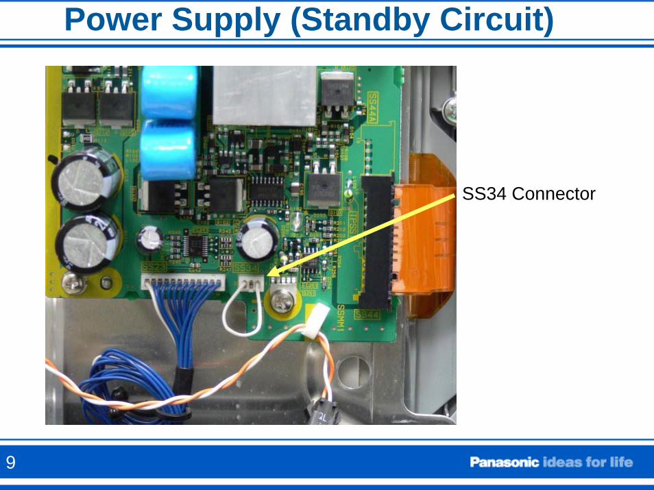
Power Supply (Standby Circuit)
SS34 Connector
9
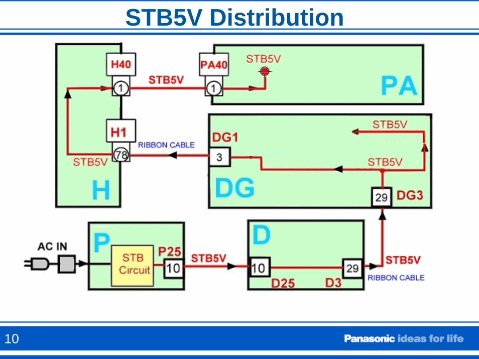
STB5V Distribution
10
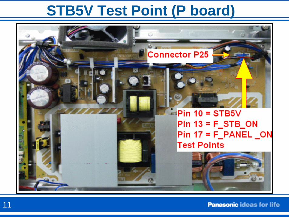
STB5V Test Point (P board)
11
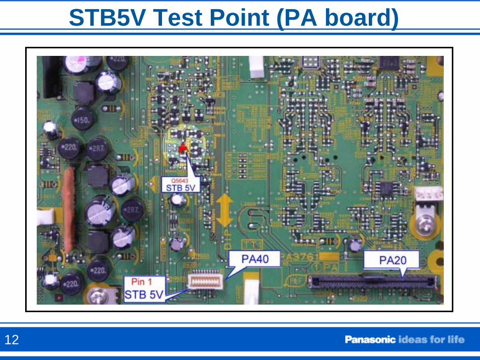
STB5V Test Point (PA board)
12
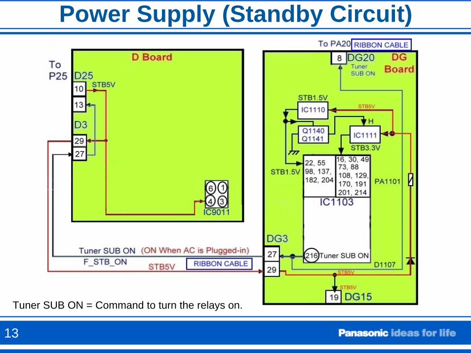
Power Supply (Standby Circuit)
Tuner SUB ON = Command to turn the relays on.
13
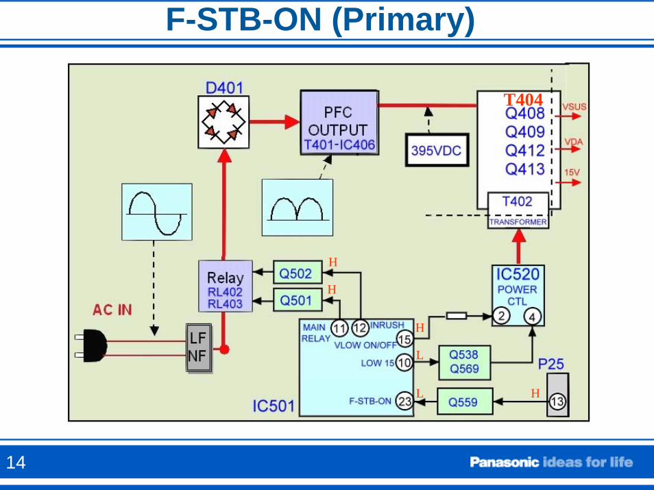
F-STB-ON (Primary)
H
H
H
L
T404
L H
14
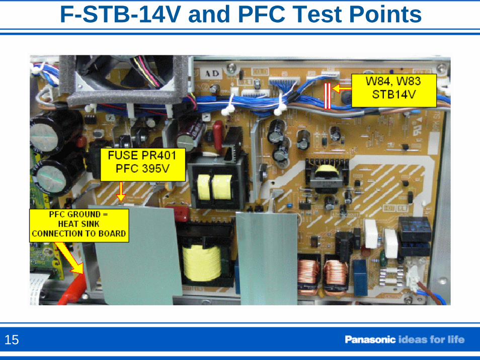
F-STB-14V and PFC Test Points
15
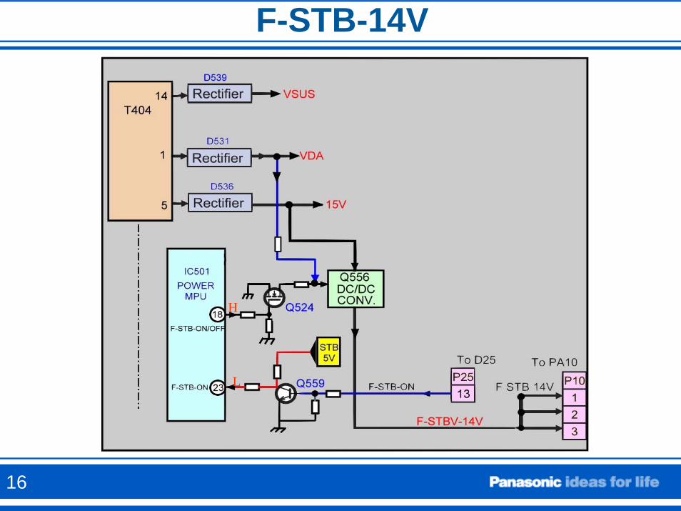
F-STB-14V
L
H
16
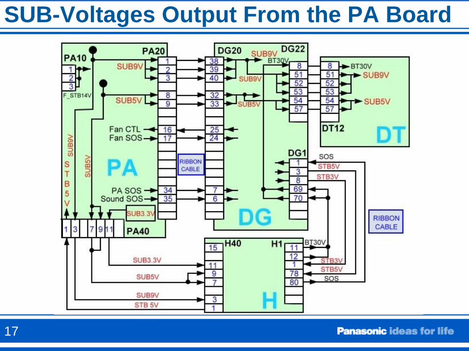
SUB-Voltages Output From the PA Board
17
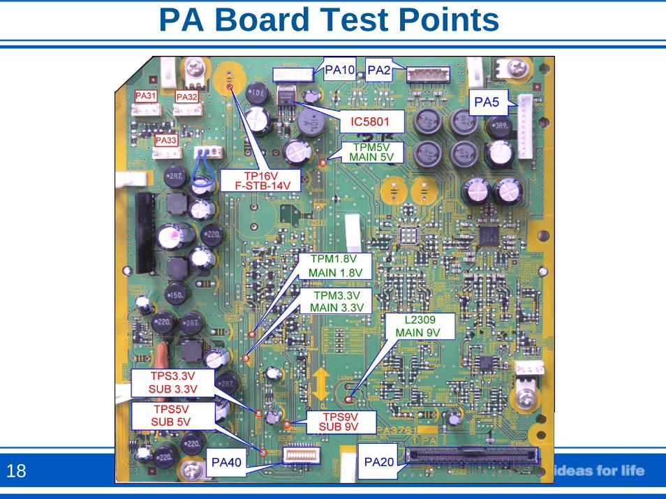
PA Board Test Points
18
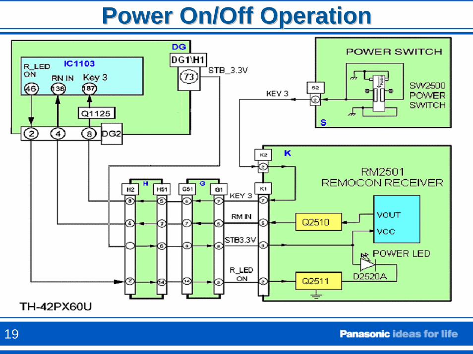
Power On/Off OperationPower On/Off Operation
19
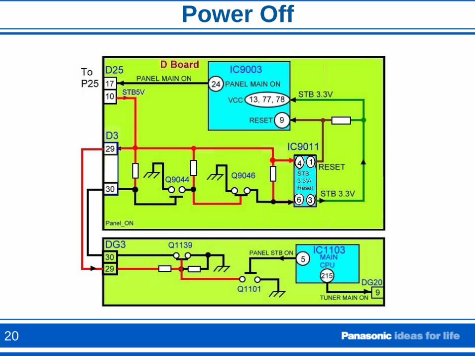
Power Off
20
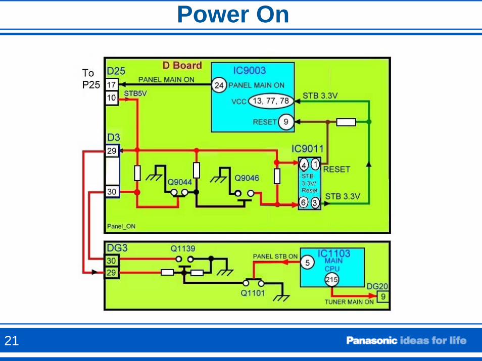
Power On
21
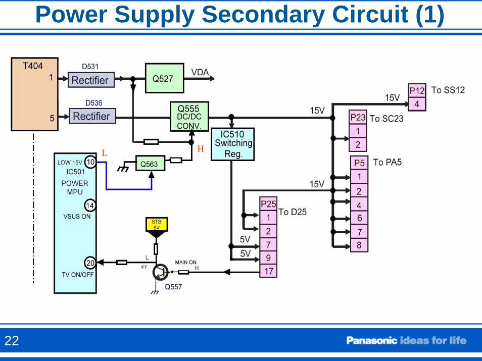
Power Supply Secondary Circuit (1)
L H
22
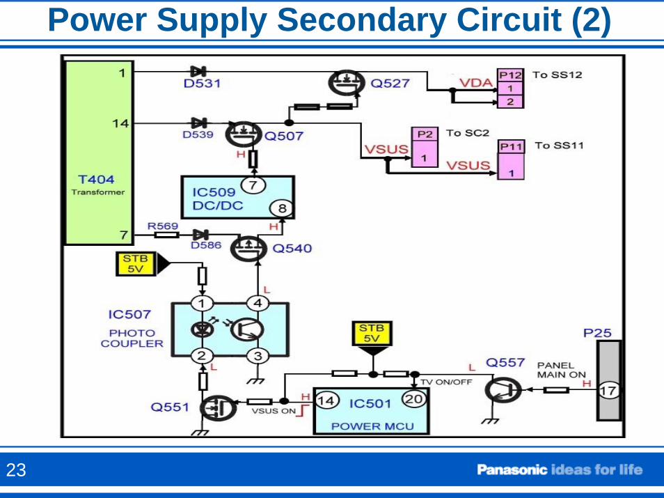
Power Supply Secondary Circuit (2)
23
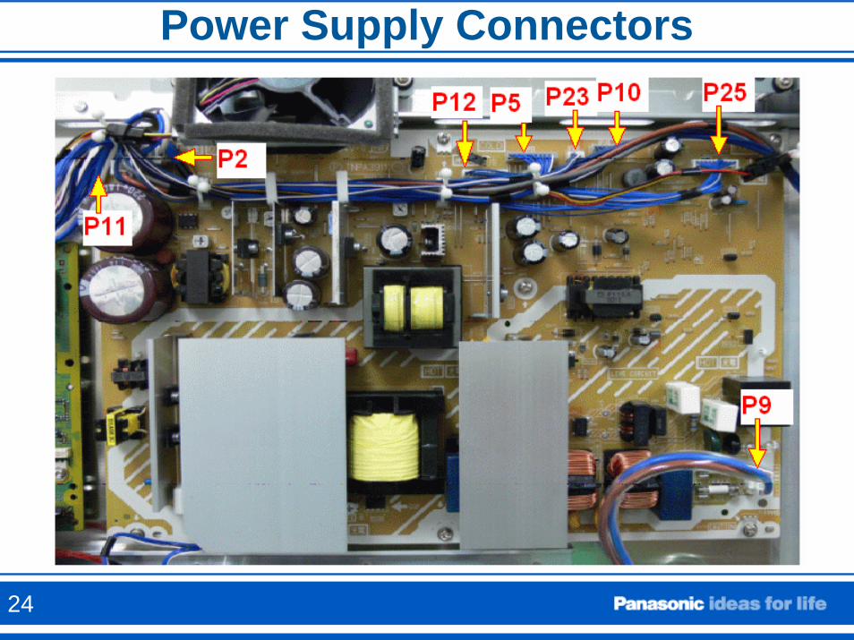
Power Supply Connectors
24
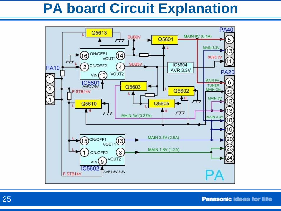
PA board Circuit Explanation
25
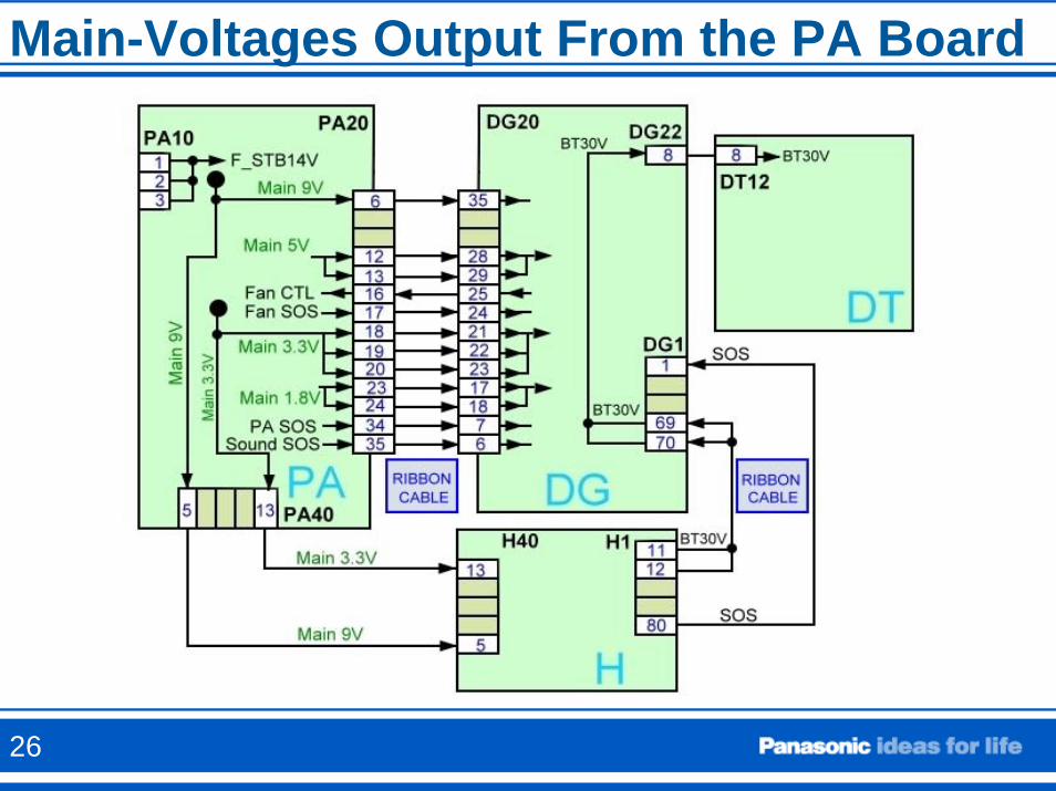
Main-Voltages Output From the PA Board
26
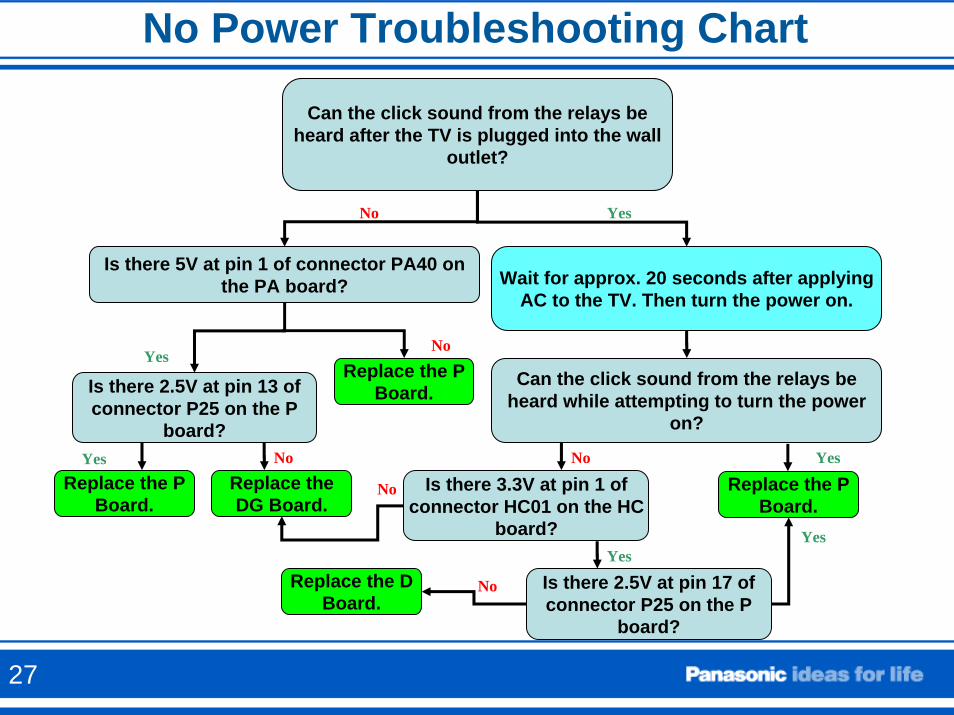
No Power Troubleshooting Chart
Can the click sound from the relays be heard after the TV is plugged into the wall
outlet?
Is there 5V at pin 1 of connector PA40 on the PA board? Wait for approx. 20 seconds after applying
AC to the TV. Then turn the power on.
Is there 2.5V at pin 13 of connector P25 on the P
board?
Can the click sound from the relays be heard while attempting to turn the power
on?
Replace the P Board.
NoYes
Replace the DG Board.
Replace the P Board.
NoYes
YesNo
Is there 3.3V at pin 1 of connector HC01 on the HC
board?
Replace the P Board.
YesNo
No
Is there 2.5V at pin 17 of connector P25 on the P
board?
Yes
NoReplace the D Board.
Yes
27
Shutdown Detect Circuits
Understanding how the SHUTDOWN circuit works
SOS28
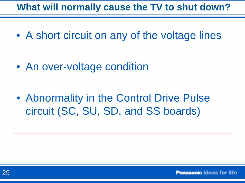
What will normally cause the TV to shut down?
• A short circuit on any of the voltage lines
• An over-voltage condition
• Abnormality in the Control Drive Pulse circuit (SC, SU, SD, and SS boards)
29
Cases When Missing Voltages Can Cause the TV to Shut Down
• Missing the source voltage to the PA board (STB14V) from the P board
• Missing output voltage from the PA board to the DG board.
• Missing 15V or VSUS on either the SS or SC boards while the control drive pulses from the D board are being provided
30
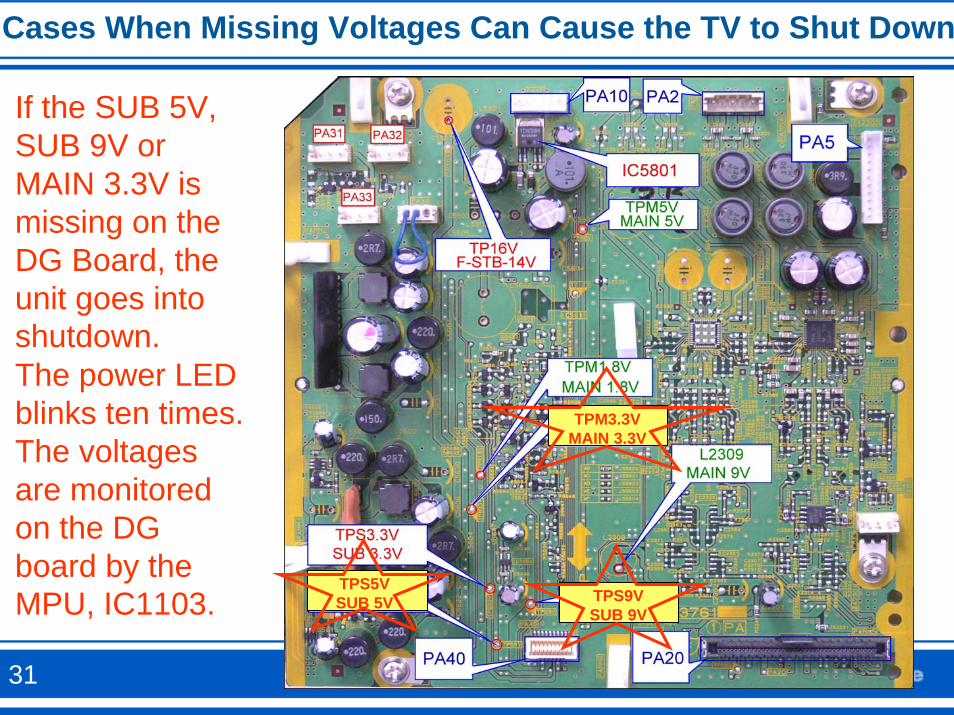
Cases When Missing Voltages Can Cause the TV to Shut Down
TPS5VSUB 5V TPS9V
SUB 9V
TPM3.3VMAIN 3.3V
If the SUB 5V, SUB 9V or MAIN 3.3V is missing on the DG Board, the unit goes into shutdown.The power LED blinks ten times. The voltages are monitored on the DG board by the MPU, IC1103.
31
TV Shutdown due to Over-voltage or Short Circuit
This could happen if there’s a short circuit in one of the B+ lines from the PA board, an over-voltage condition, or missing STB 14V from the P board.
32
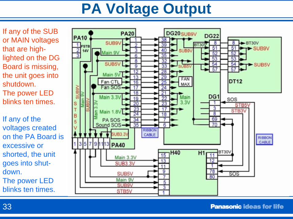
PA Voltage OutputIf any of the SUB or MAIN voltagesthat are high-lighted on the DG Board is missing, the unit goes into shutdown.The power LED blinks ten times.
If any of the voltages created on the PA Board is excessive or shorted, the unit goes into shut-down.The power LED blinks ten times.
33
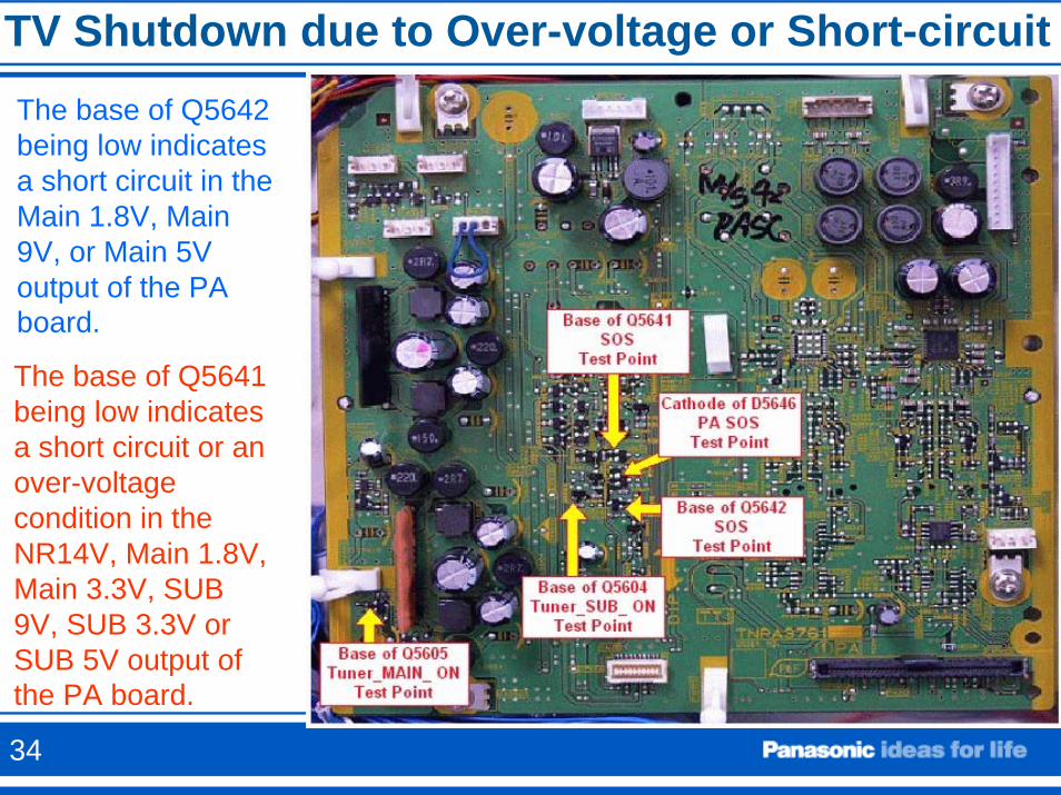
TV Shutdown due to Over-voltage or Short-circuitThe base of Q5642 being low indicates a short circuit in the Main 1.8V, Main 9V, or Main 5V output of the PA board.
The base of Q5641 being low indicates a short circuit or an over-voltage condition in the NR14V, Main 1.8V, Main 3.3V, SUB 9V, SUB 3.3V or SUB 5V output of the PA board.
34
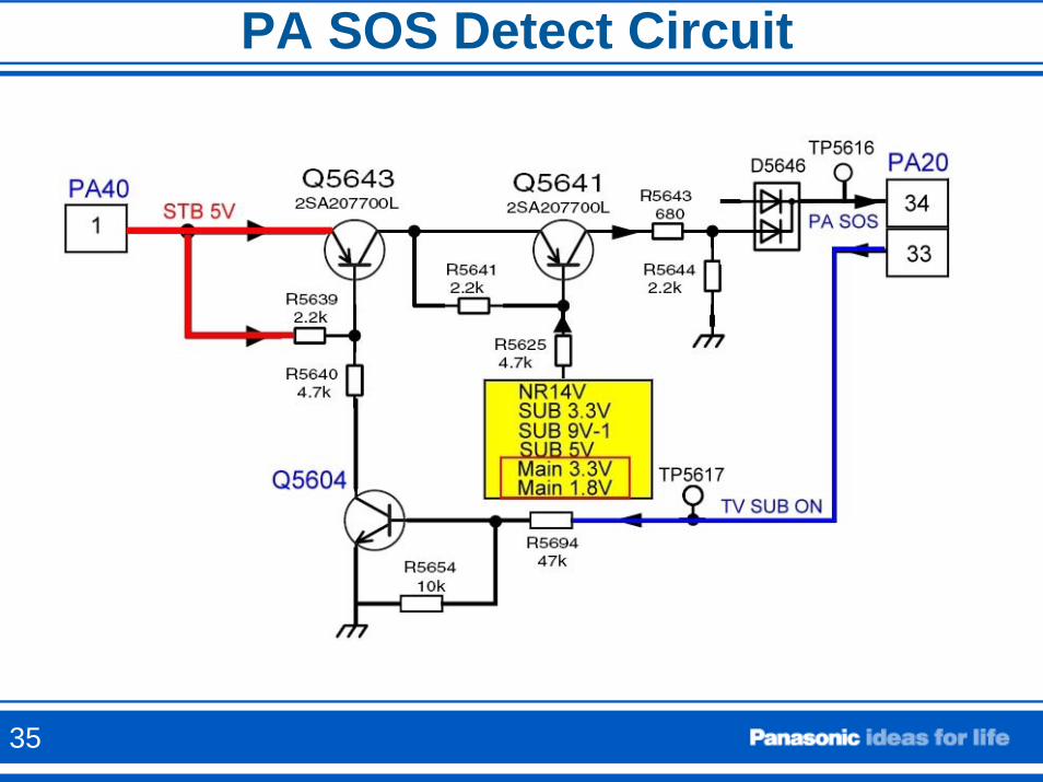
PA SOS Detect Circuit
35
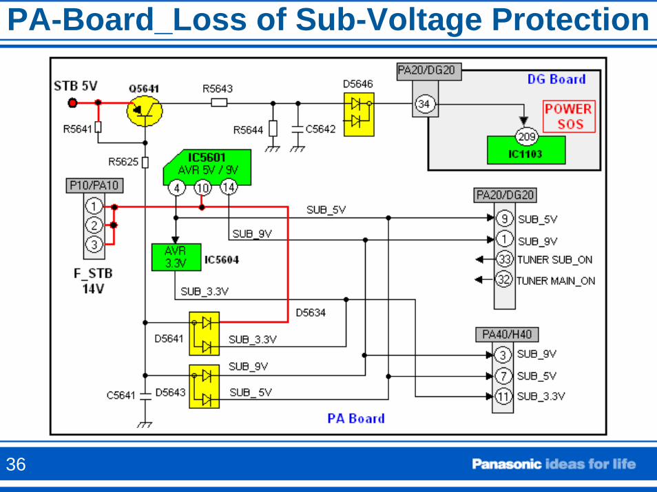
PA-Board_Loss of Sub-Voltage Protection
36
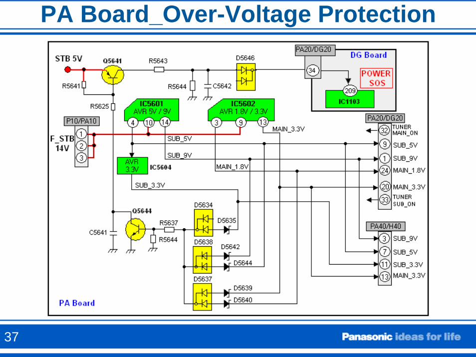
PA Board_Over-Voltage Protection
37
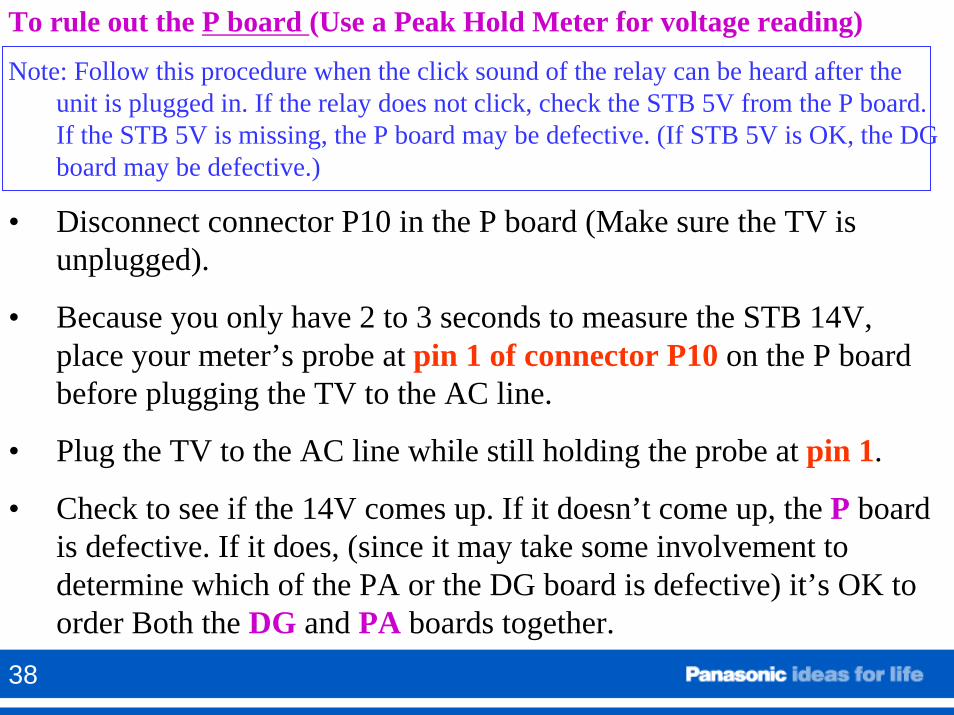
To rule out the P board (Use a Peak Hold Meter for voltage reading)
Note: Follow this procedure when the click sound of the relay can be heard after the unit is plugged in. If the relay does not click, check the STB 5V from the P board. If the STB 5V is missing, the P board may be defective. (If STB 5V is OK, the DG board may be defective.)
• Disconnect connector P10 in the P board (Make sure the TV is unplugged).
• Because you only have 2 to 3 seconds to measure the STB 14V, place your meter’s probe at pin 1 of connector P10 on the P board before plugging the TV to the AC line.
• Plug the TV to the AC line while still holding the probe at pin 1.
• Check to see if the 14V comes up. If it doesn’t come up, the P board is defective. If it does, (since it may take some involvement todetermine which of the PA or the DG board is defective) it’s OK to order Both the DG and PA boards together.
38
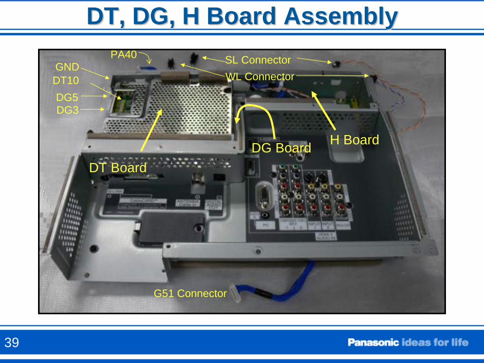
DT, DG, H Board AssemblyDT, DG, H Board Assembly
G51 Connector
SL ConnectorWL ConnectorDT10
DG5DG3
GNDPA40
DT Board
H BoardDG Board
39
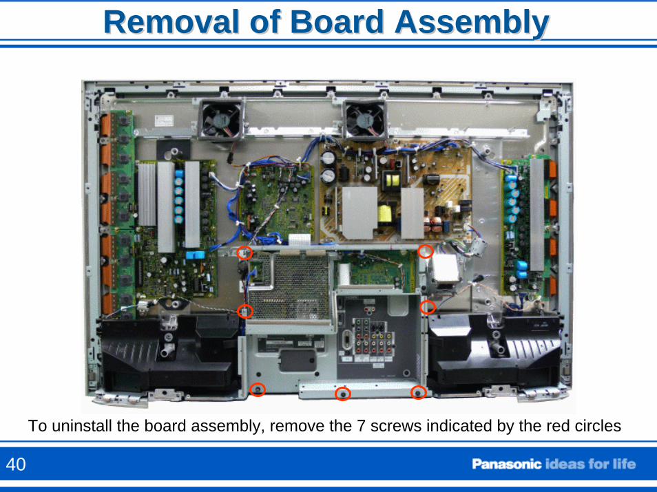
Removal of Board AssemblyRemoval of Board Assembly
To uninstall the board assembly, remove the 7 screws indicated by the red circles
40
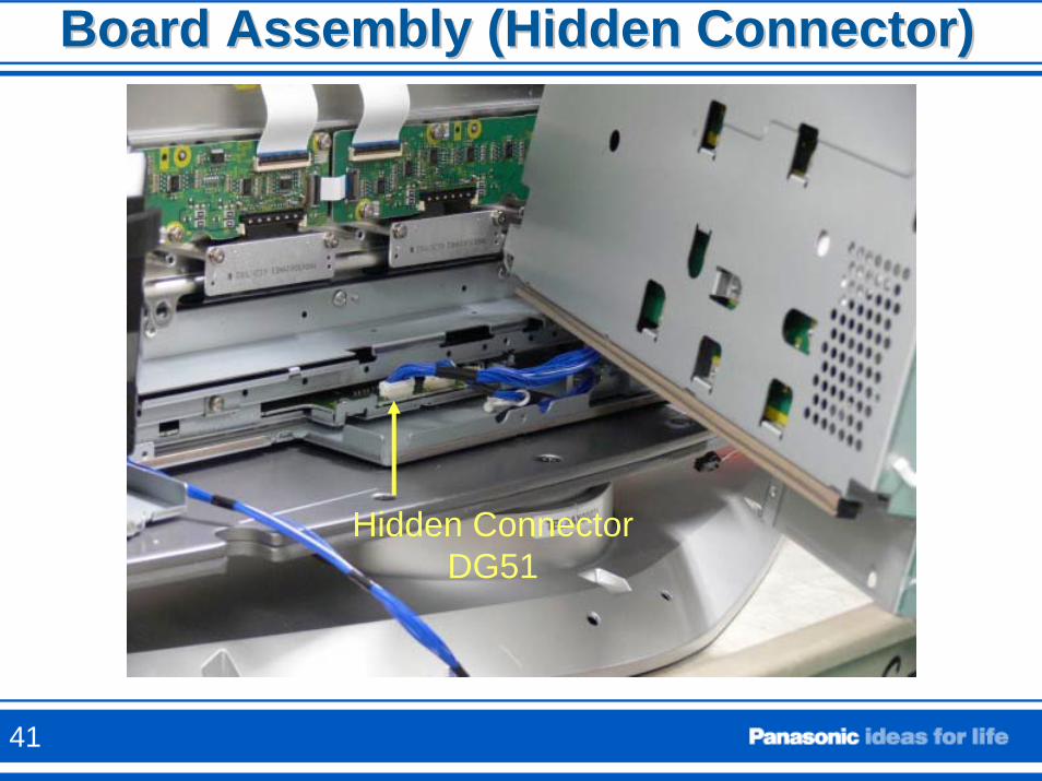
Board Assembly (Hidden Connector)Board Assembly (Hidden Connector)
Hidden ConnectorDG51
41
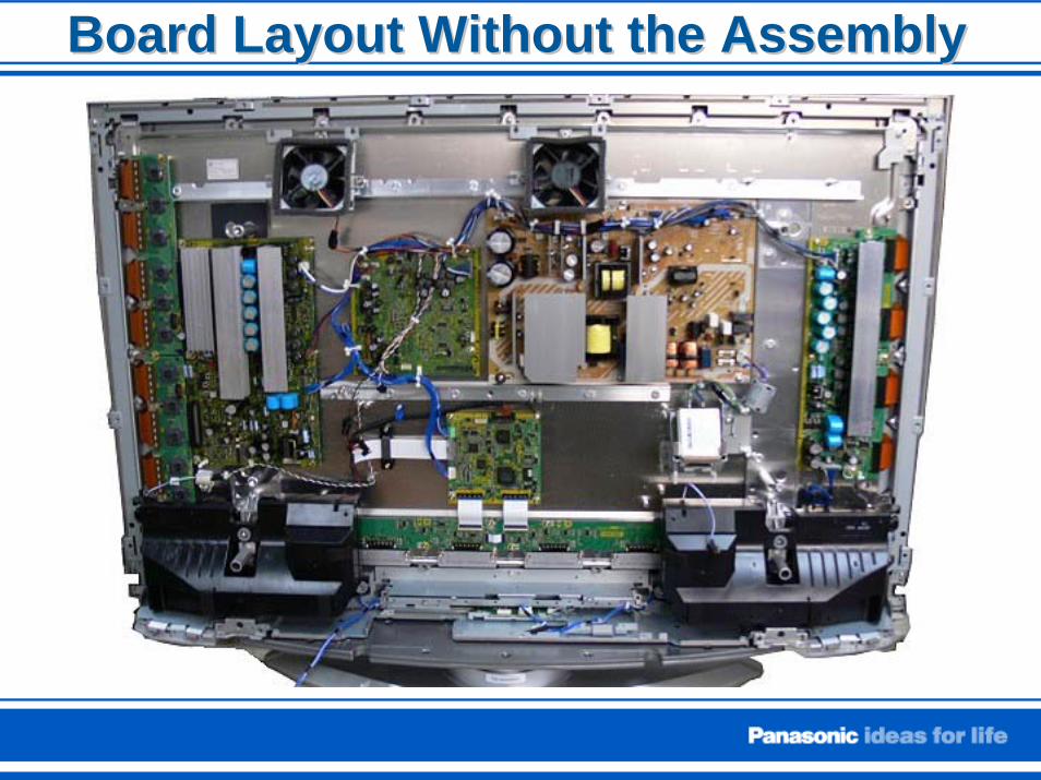
Board Layout Without the AssemblyBoard Layout Without the Assembly
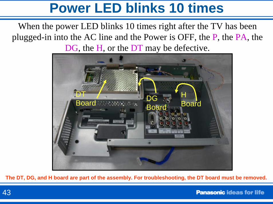
Power LED blinks 10 timesWhen the power LED blinks 10 times right after the TV has been
plugged-in into the AC line and the Power is OFF, the P, the PA, the DG, the H, or the DT may be defective.
DT Board
H Board
DG Board
The DT, DG, and H board are part of the assembly. For troubleshooting, the DT board must be removed.
43
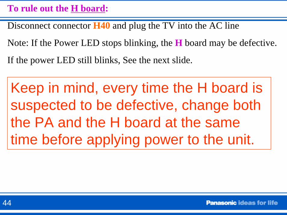
To rule out the H board:
Disconnect connector H40 and plug the TV into the AC line
Note: If the Power LED stops blinking, the H board may be defective.
If the power LED still blinks, See the next slide.
Keep in mind, every time the H board is suspected to be defective, change both the PA and the H board at the same time before applying power to the unit.
44
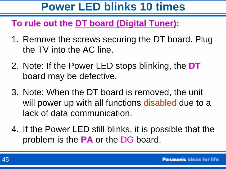
Power LED blinks 10 timesTo rule out the DT board (Digital Tuner):
1. Remove the screws securing the DT board. Plug the TV into the AC line.
2. Note: If the Power LED stops blinking, the DTboard may be defective.
3. Note: When the DT board is removed, the unit will power up with all functions disabled due to a lack of data communication.
4. If the Power LED still blinks, it is possible that the problem is the PA or the DG board.
45
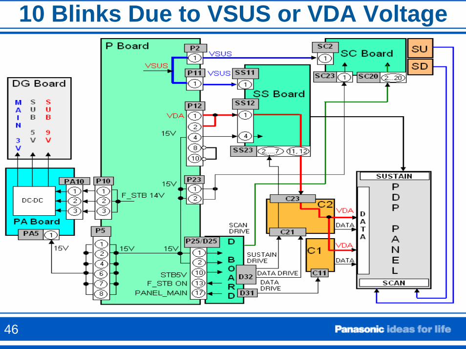
10 Blinks Due to VSUS or VDA Voltage
46
Power LED blinks 5 times
This is caused by abnormalities on the 5V line.
This could also happen if the VDA voltage is shorted.
SOS47
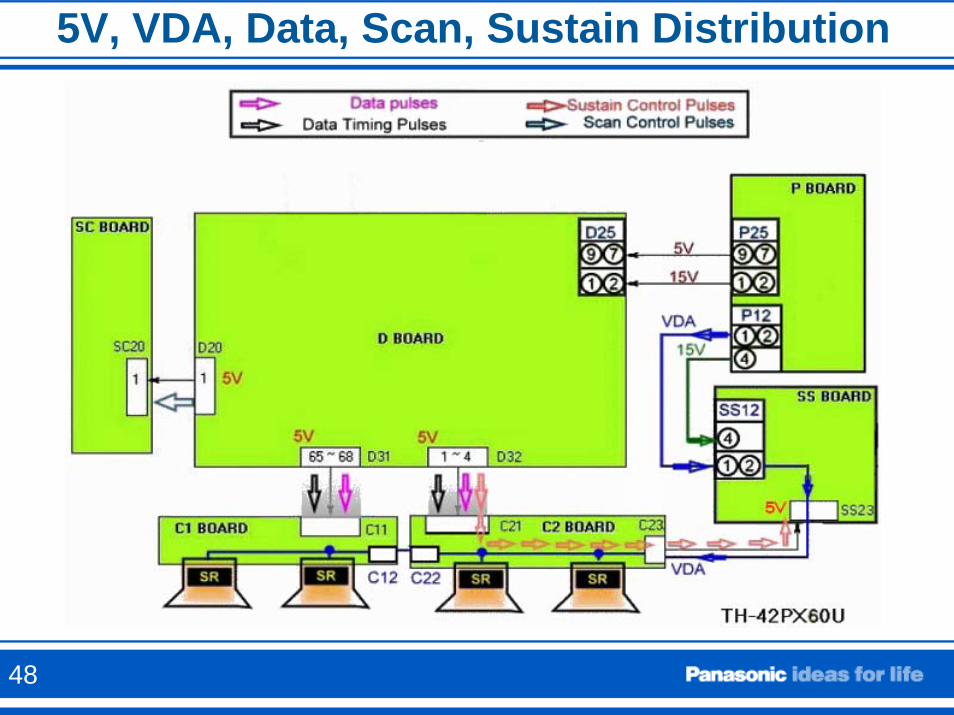
5V, VDA, Data, Scan, Sustain Distribution
48
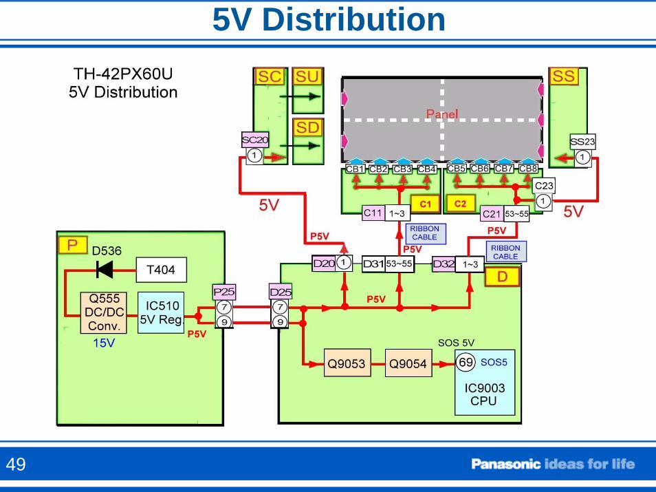
5V Distribution
49
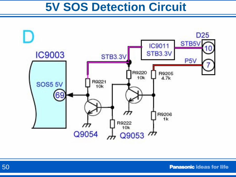
5V SOS Detection Circuit
50
Other Causes of 5V SOS
• The Power LED could also blink 5 times if the VDA voltage is shorted [Normally by the Panel (de-multiplexer ICs)].
• To understand the reason, see the next slide
51
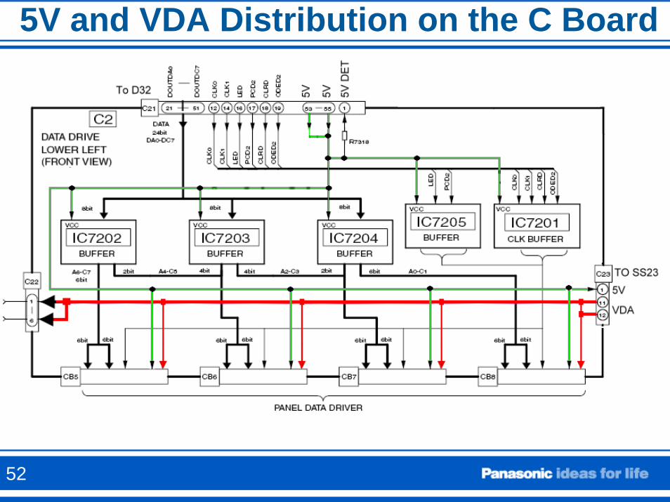
5V and VDA Distribution on the C Board
52
How to properly isolate the C boards
• When the ribbon cables from the D board to the C boards are disconnected in order to isolate the C boards, the Power LED will blink 6 times.
• The following circuit explains the reason why.• To properly isolate the C boards without having
the Power LED blink, the test point TP9387 (Labeled TP9387 on the D board) should be grounded through a 1K resistor.
• The VDA connector should be also disconnected.
53
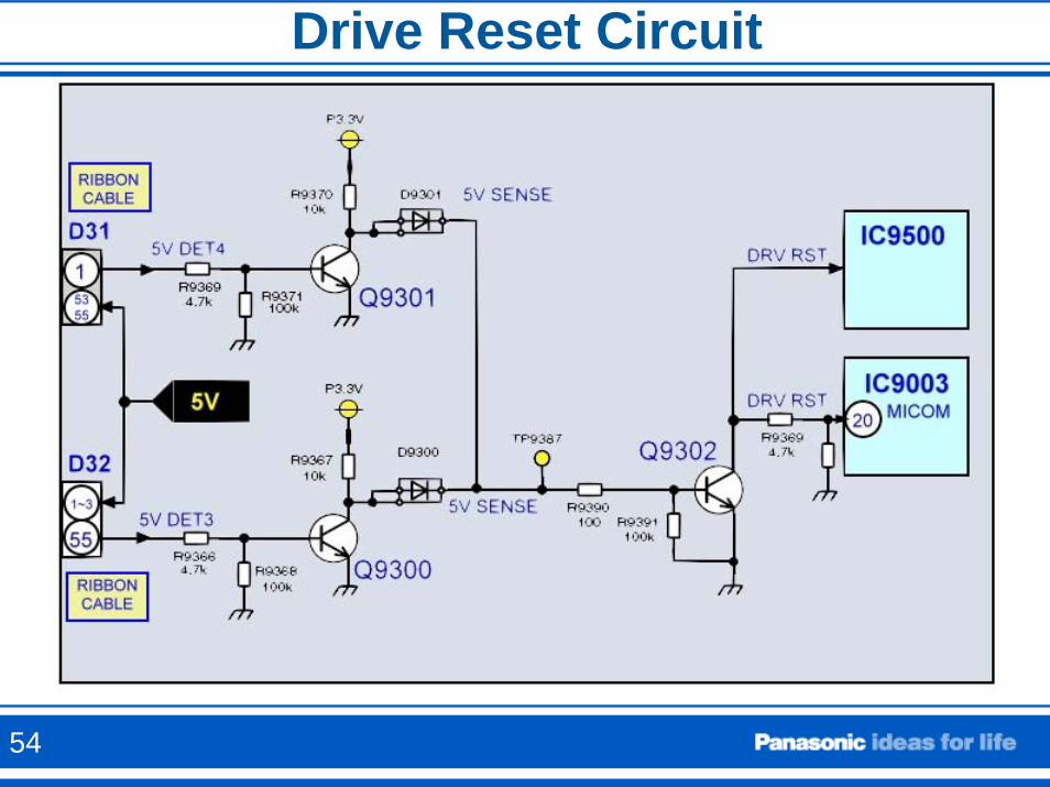
Drive Reset Circuit
54
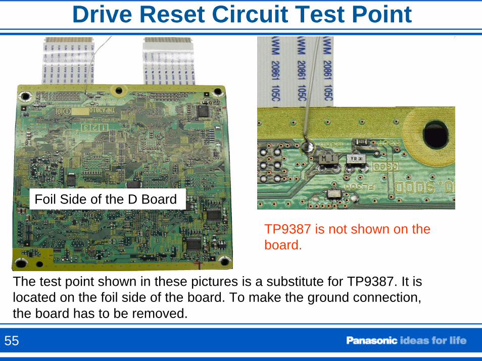
Drive Reset Circuit Test Point
The test point shown in these pictures is a substitute for TP9387. It is located on the foil side of the board. To make the ground connection,the board has to be removed.
TP9387 is not shown on the board.
Foil Side of the D Board
55
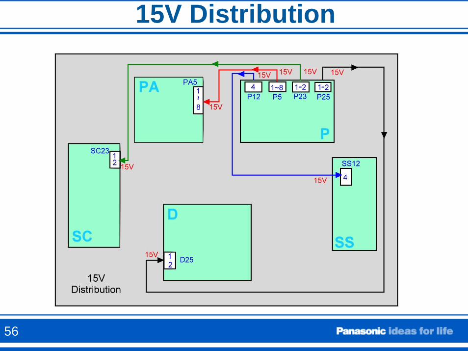
15V Distribution
56
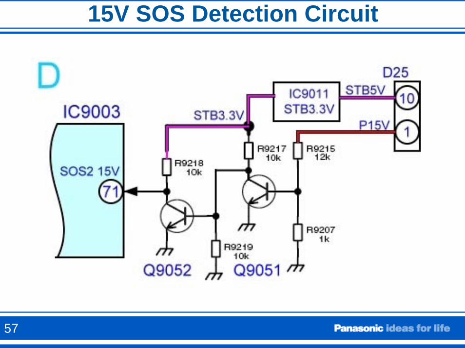
15V SOS Detection Circuit
57
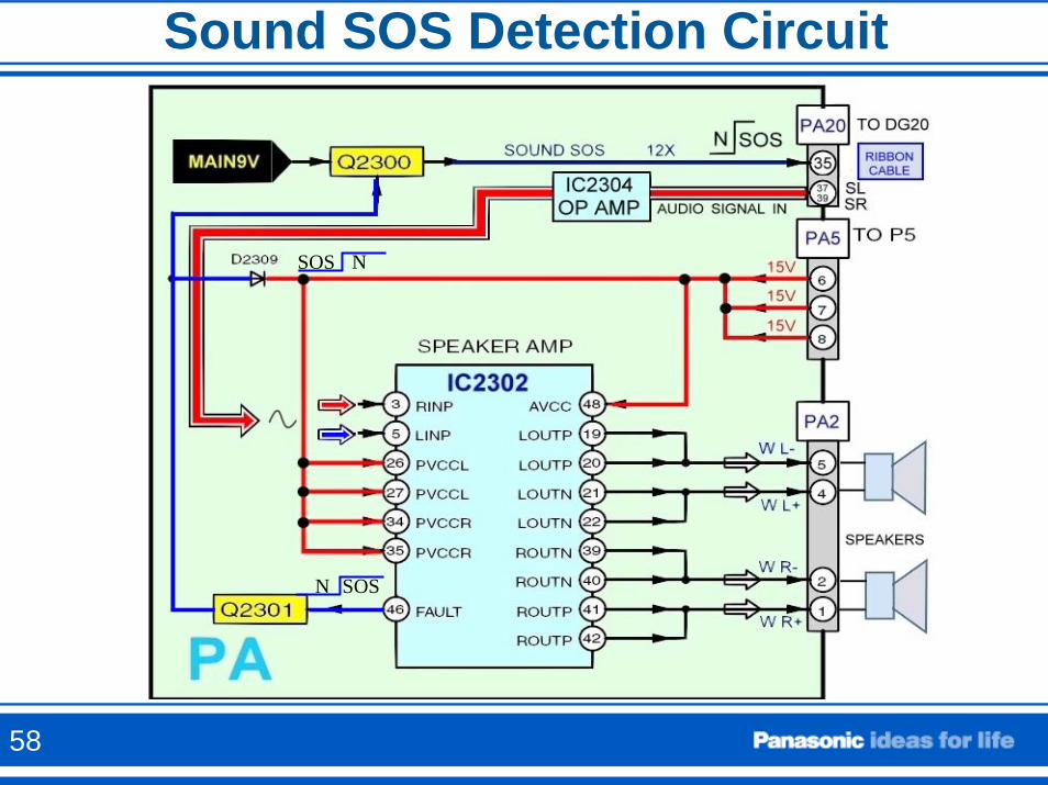
Sound SOS Detection Circuit
N SOS
SOS N
58
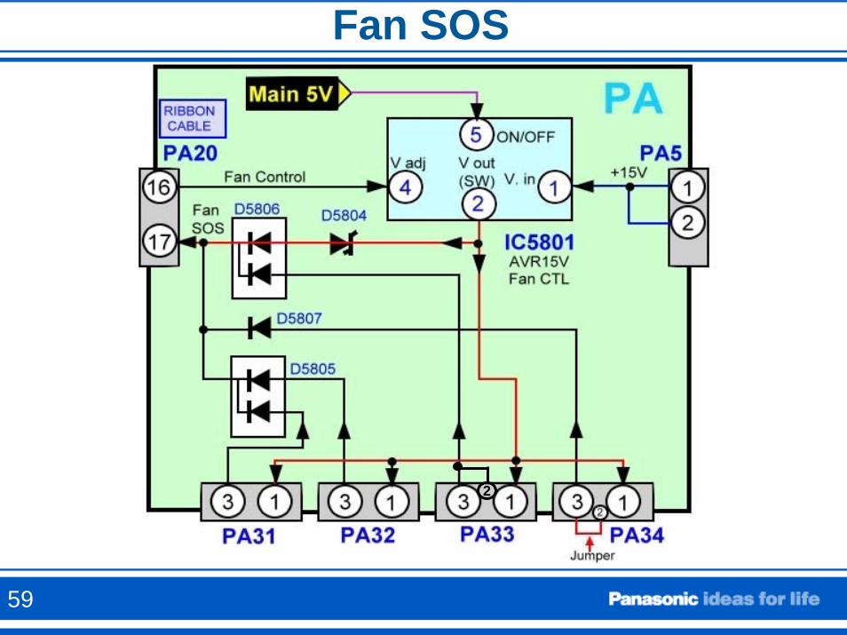
Fan SOS
2
59
Fan SOS
To determine if a fan is the cause of the 11 blinks of the power LED, simply use a peak-hold voltmeter to determine if pin 3 of the fan connector goes High before shutdown. If it does, the fan is defective. If it does not, check the other fans and the fan drive drive circuit.
60
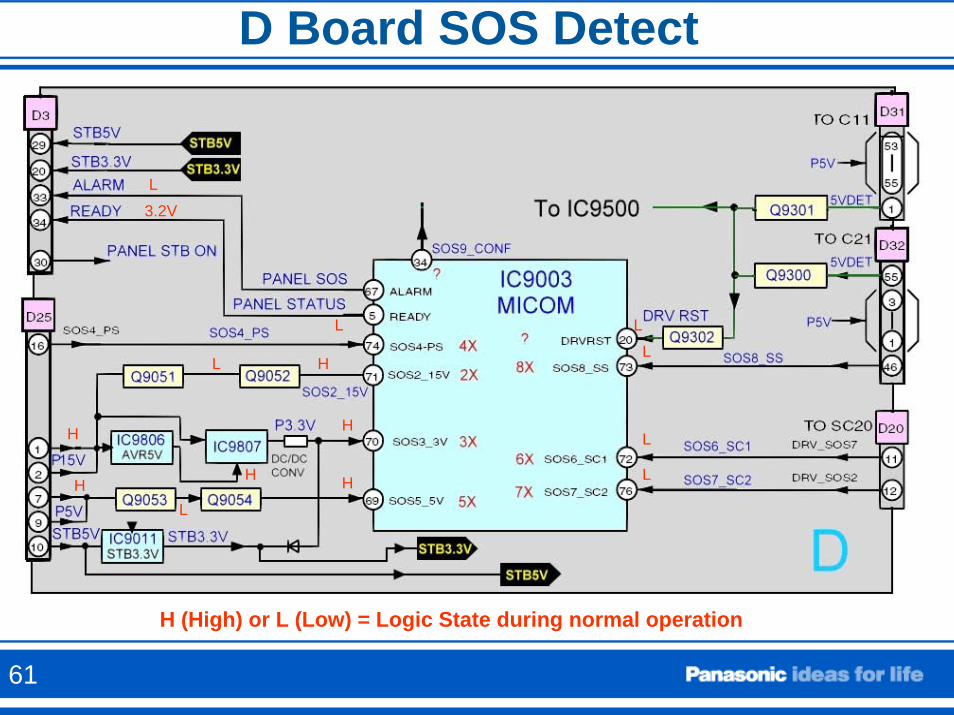
D Board SOS Detect
HL
H
H
L H
H
3.2VL
LL
L
L
L
H
H (High) or L (Low) = Logic State during normal operation
61
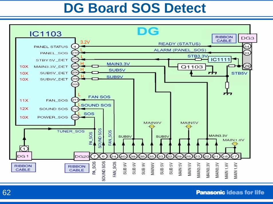
DG Board SOS Detect
L
L
L
3.2V
LLHHH
62
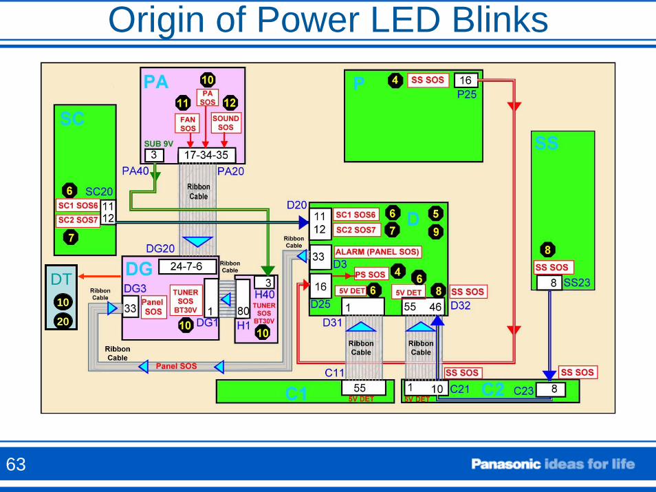
Origin of Power LED Blinks
DT10
20
63
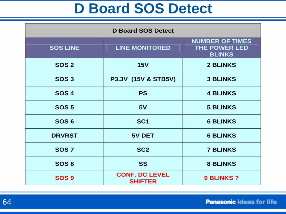
D Board SOS DetectD Board SOS Detect
SOS LINE LINE MONITORED NUMBER OF TIMES THE POWER LED
BLINKS
SOS 2 15V 2 BLINKS
SOS 3 P3.3V (15V & STB5V) 3 BLINKS
SOS 4 PS 4 BLINKS
SOS 5 5V 5 BLINKS
SOS 6 SC1 6 BLINKS
DRVRST 5V DET 6 BLINKS
SOS 7 SC2 7 BLINKS
SOS 8 SS 8 BLINKS
SOS 9 CONF. DC LEVEL SHIFTER 9 BLINKS ?
64
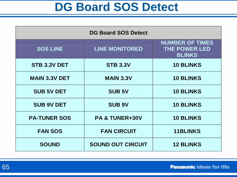
DG Board SOS Detect
DG Board SOS Detect
SOS LINE LINE MONITORED NUMBER OF TIMES THE POWER LED
BLINKS
STB 3.3V DET STB 3.3V 10 BLINKS
MAIN 3.3V DET MAIN 3.3V 10 BLINKS
SUB 5V DET SUB 5V 10 BLINKS
SUB 9V DET SUB 9V 10 BLINKS
PA-TUNER SOS PA & TUNER+30V 10 BLINKS
FAN SOS FAN CIRCUIT 11BLINKS
SOUND SOUND OUT CIRCUIT 12 BLINKS
65
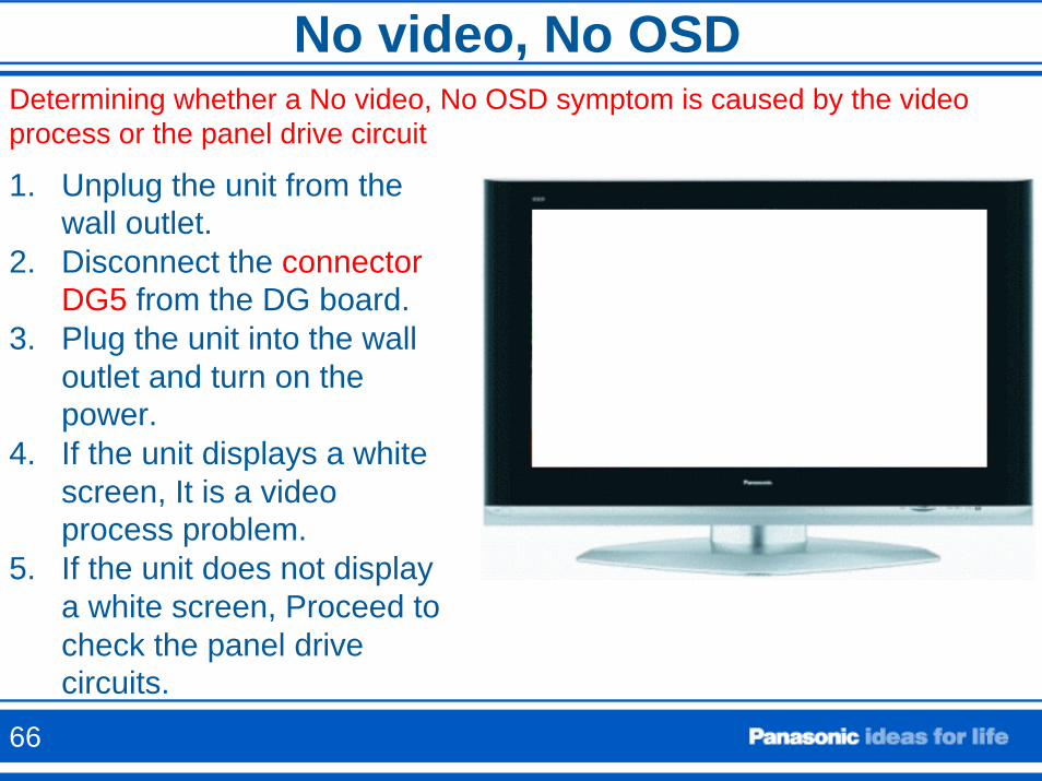
No video, No OSDDetermining whether a No video, No OSD symptom is caused by the video process or the panel drive circuit
1. Unplug the unit from the wall outlet.
2. Disconnect the connector DG5 from the DG board.
3. Plug the unit into the wall outlet and turn on the power.
4. If the unit displays a white screen, It is a video process problem.
5. If the unit does not display a white screen, Proceed to check the panel drive circuits.
66
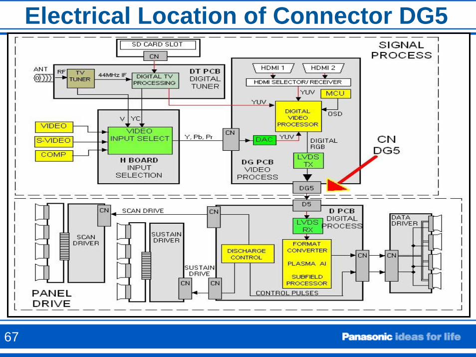
Electrical Location of Connector DG5
67
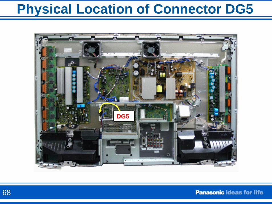
Physical Location of Connector DG5
DG5
68
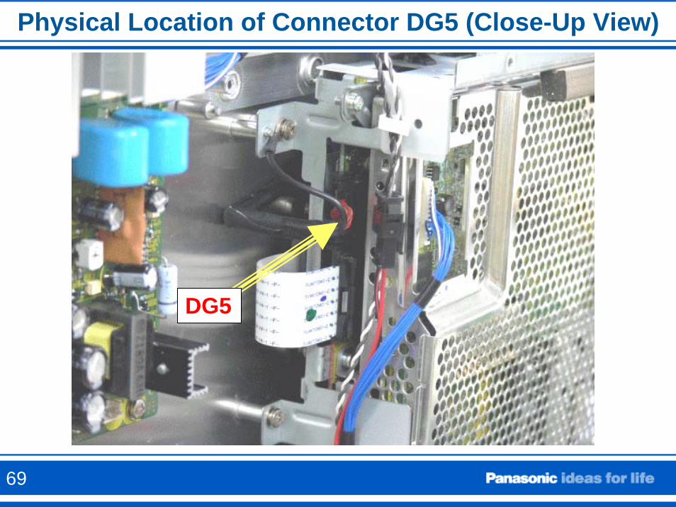
Physical Location of Connector DG5 (Close-Up View)
DG5
69
Isolation of the SC and SS Boards
If any of the connectors providing the 15V or VSUS voltage to the SC or SS board is disconnected while the connectors that provide the Scan and Sustain Drive pulses from the D board are still connected, the TV will shut down.
70
Isolation of the SC and SS Boards
Precaution: Do not let the TV run for more than 30 seconds while isolating any of the circuit boards.
The Scan Board (SC) and the Sustain (SS) board could be easily isolated.
This can be useful to diagnose: 1. Shutdown Problems2. Video Problems.
71
Isolation of the SC Board
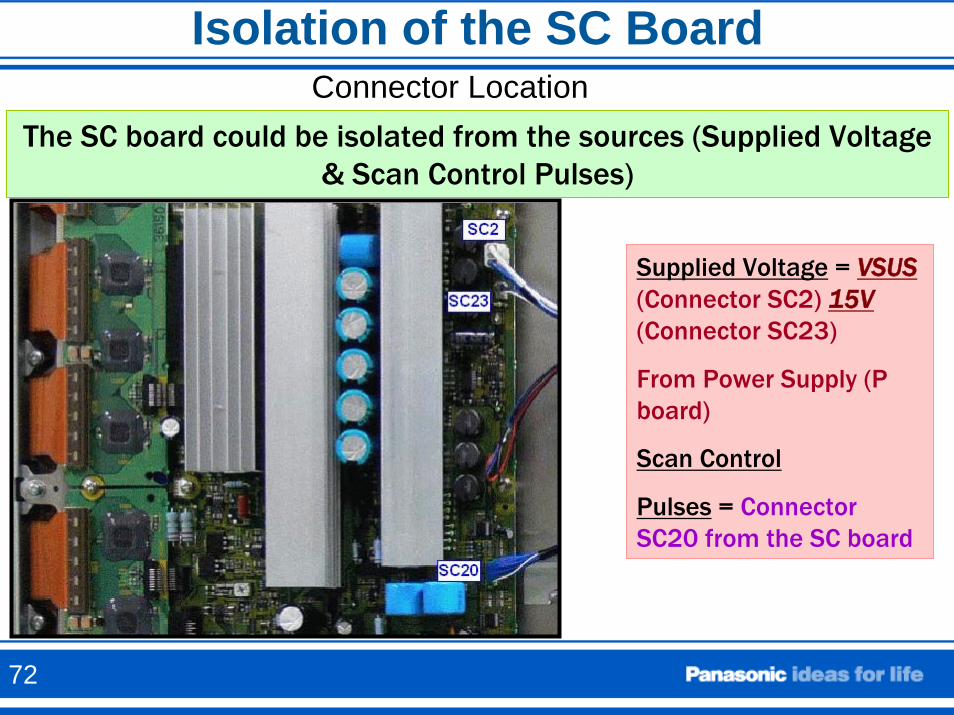
The SC board could be isolated from the sources (Supplied Voltage & Scan Control Pulses)
Supplied Voltage = VSUS(Connector SC2) 15V(Connector SC23)
From Power Supply (P board)
Scan Control
Pulses = Connector SC20 from the SC board
Connector Location
72
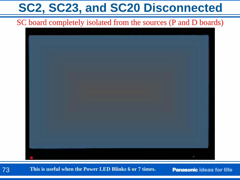
SC2, SC23, and SC20 DisconnectedSC board completely isolated from the sources (P and D boards)
This is useful when the Power LED Blinks 6 or 7 times.73
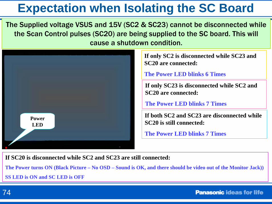
Expectation when Isolating the SC BoardThe Supplied voltage VSUS and 15V (SC2 & SC23) cannot be disconnected while
the Scan Control pulses (SC20) are being supplied to the SC board. This will cause a shutdown condition.
PowerLED
If only SC2 is disconnected while SC23 and SC20 are connected:
The Power LED blinks 6 Times
If only SC23 is disconnected while SC2 and SC20 are connected:
The Power LED blinks 7 Times
If both SC2 and SC23 are disconnected while SC20 is still connected:
The Power LED blinks 7 Times
If SC20 is disconnected while SC2 and SC23 are still connected:The Power turns ON (Black Picture – No OSD – Sound is OK, and there should be video out of the Monitor Jack))
SS LED is ON and SC LED is OFF
74
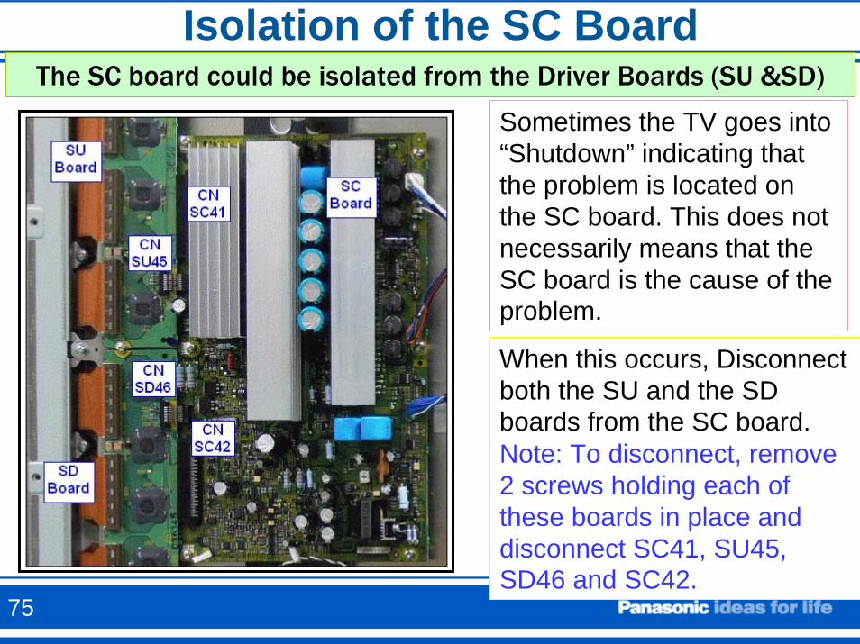
Isolation of the SC BoardThe SC board could be isolated from the Driver Boards (SU &SD)
Sometimes the TV goes into “Shutdown” indicating that the problem is located on the SC board. This does not necessarily means that the SC board is the cause of the problem.
When this occurs, Disconnect both the SU and the SD boards from the SC board.Note: To disconnect, remove 2 screws holding each of these boards in place and disconnect SC41, SU45, SD46 and SC42.
75
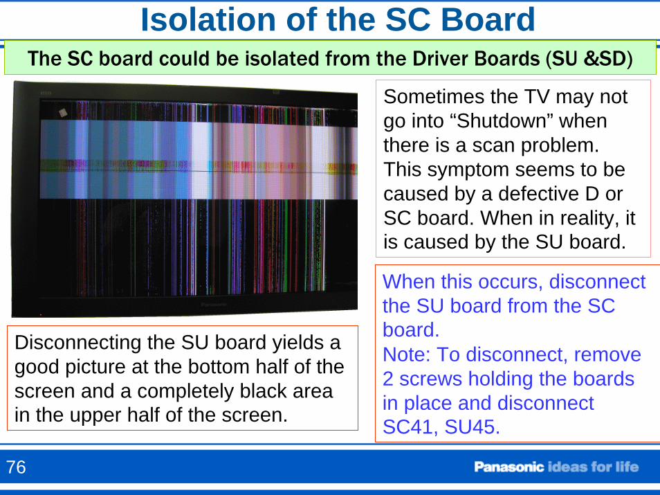
Isolation of the SC BoardThe SC board could be isolated from the Driver Boards (SU &SD)
Sometimes the TV may not go into “Shutdown” when there is a scan problem. This symptom seems to be caused by a defective D or SC board. When in reality, it is caused by the SU board.
When this occurs, disconnect the SU board from the SC board.Note: To disconnect, remove 2 screws holding the boards in place and disconnect SC41, SU45.
Disconnecting the SU board yields a good picture at the bottom half of the screen and a completely black area in the upper half of the screen.
76
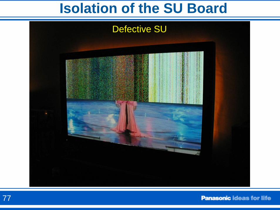
Isolation of the SU BoardDefective SU
77
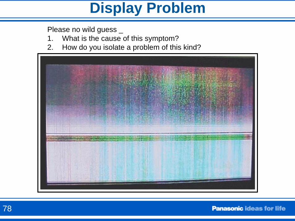
Display ProblemPlease no wild guess _ 1. What is the cause of this symptom?2. How do you isolate a problem of this kind?
78
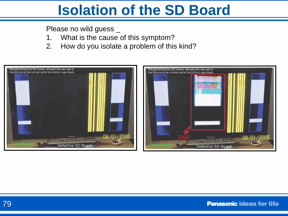
Isolation of the SD BoardPlease no wild guess _ 1. What is the cause of this symptom?2. How do you isolate a problem of this kind?
79
Supply Voltage from P to SS board
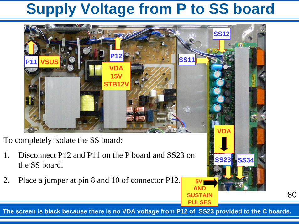
The screen is black because there is no VDA voltage from P12 of SS23 provided to the C boards.
To completely isolate the SS board:
1. Disconnect P12 and P11 on the P board and SS23 on the SS board.
2. Place a jumper at pin 8 and 10 of connector P12.
P11 VSUSP12
VDA15V
STB12V
SS11
SS12
SS23
VDA
SS34
5V AND
SUSTAINPULSES
80
Supply Voltage from P to SS board
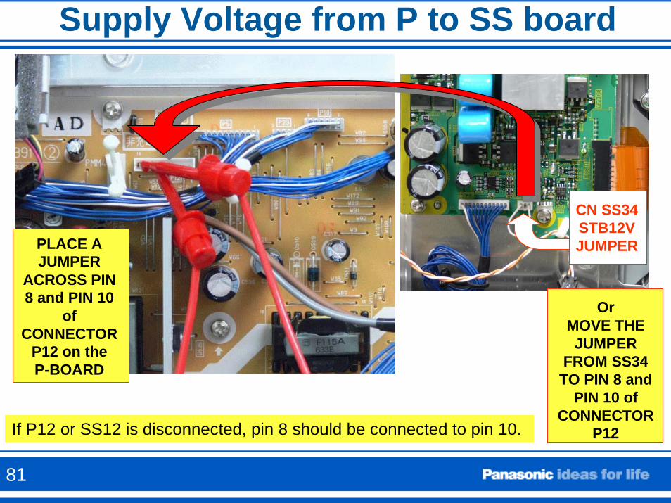
If P12 or SS12 is disconnected, pin 8 should be connected to pin 10.
OrMOVE THE JUMPER
FROM SS34 TO PIN 8 and
PIN 10 of CONNECTOR
P12
CN SS34STB12VJUMPERPLACE A
JUMPERACROSS PIN 8 and PIN 10
of CONNECTOR
P12 on theP-BOARD
81
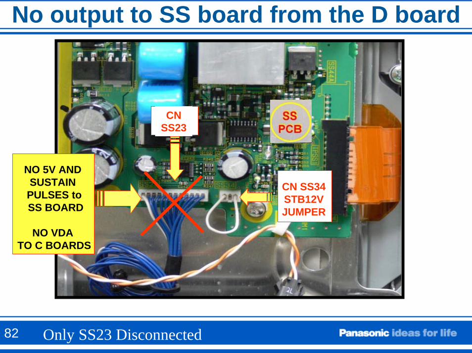
No output to SS board from the D board
NO 5V AND SUSTAIN PULSES toSS BOARD
NO VDA TO C BOARDS
CN SS23
CN SS34STB12VJUMPER
Only SS23 Disconnected82
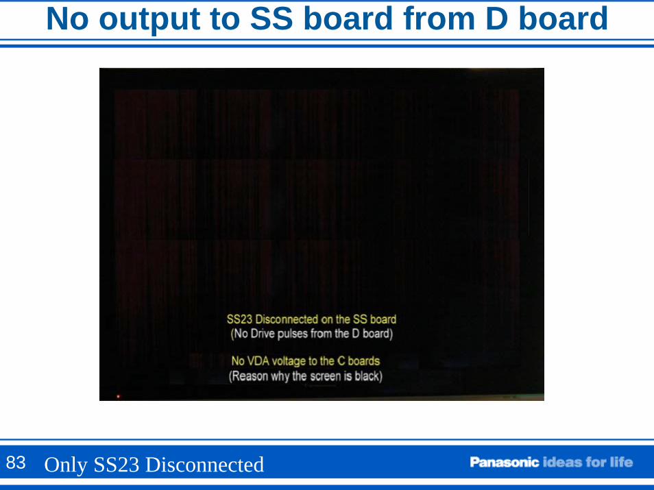
No output to SS board from D board
Only SS23 Disconnected83
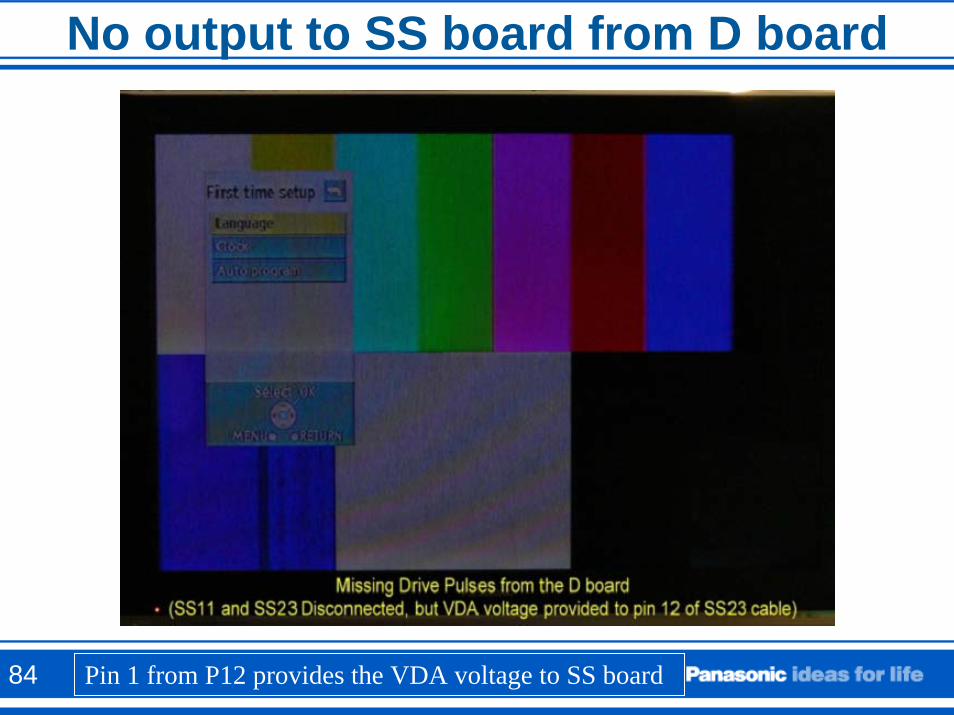
No output to SS board from D boardNo Sustain Control Pulses and No VSUS
84 Pin 1 from P12 provides the VDA voltage to SS board
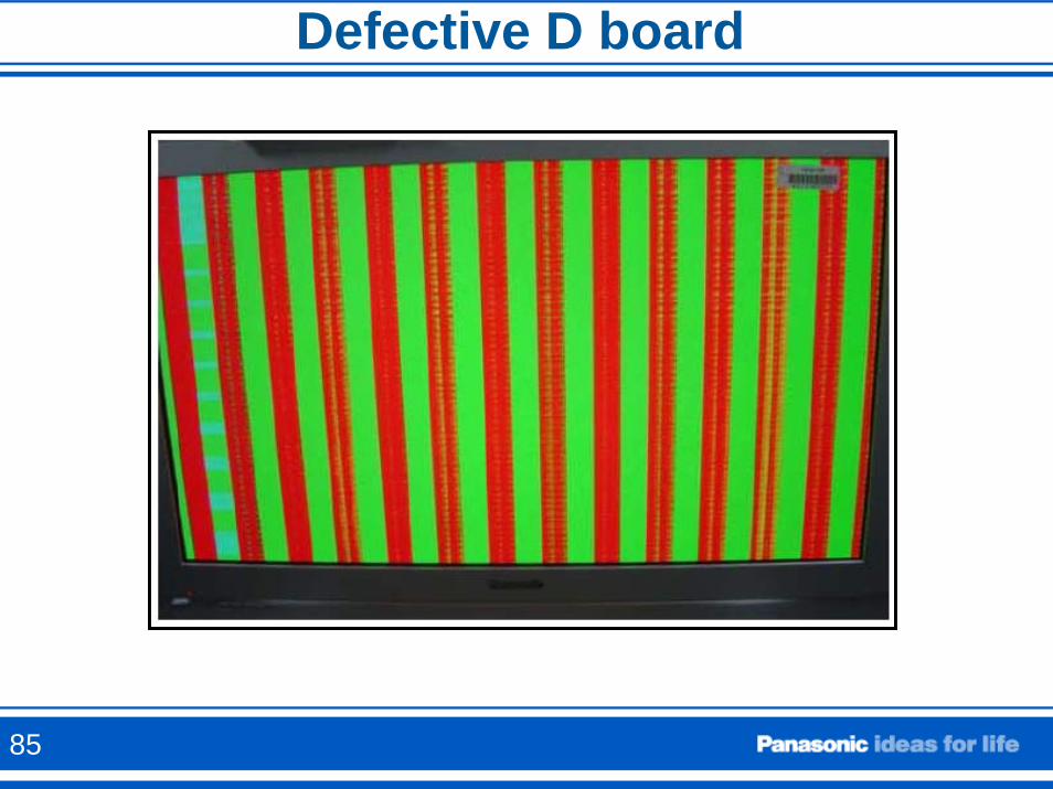
Defective D board
85
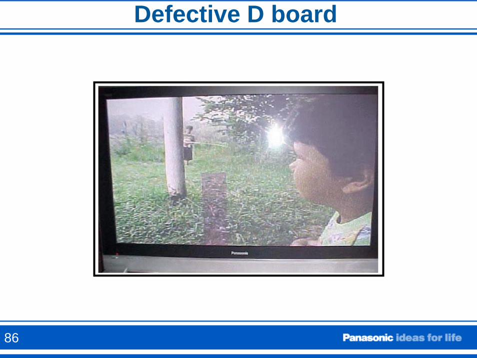
Defective D board
86
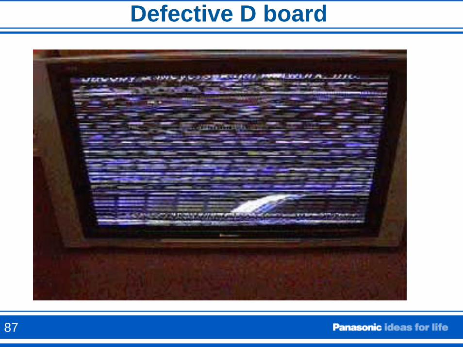
Defective D board
87
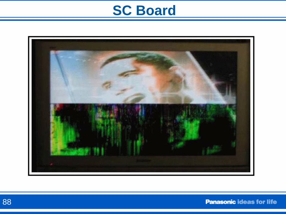
SC Board
88
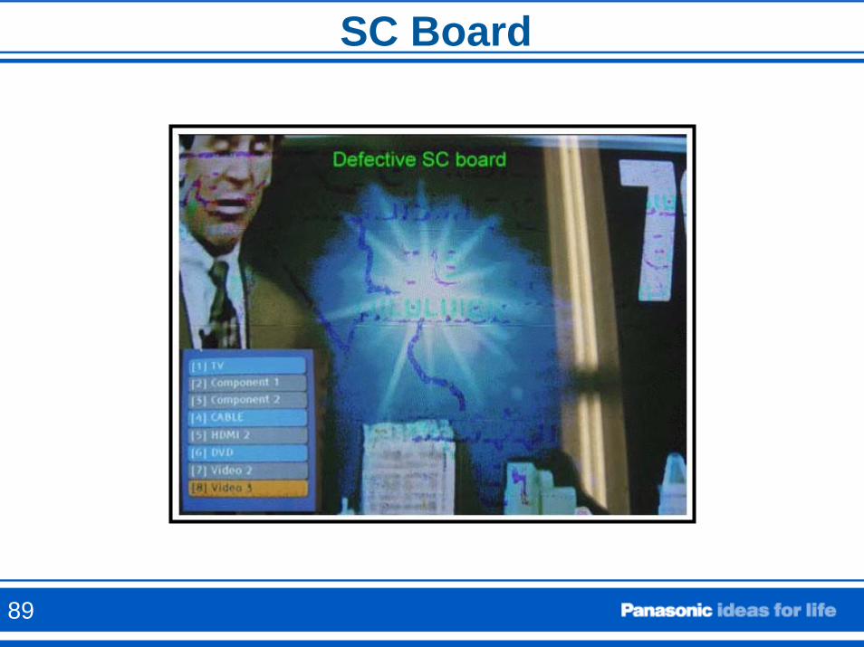
SC Board
89
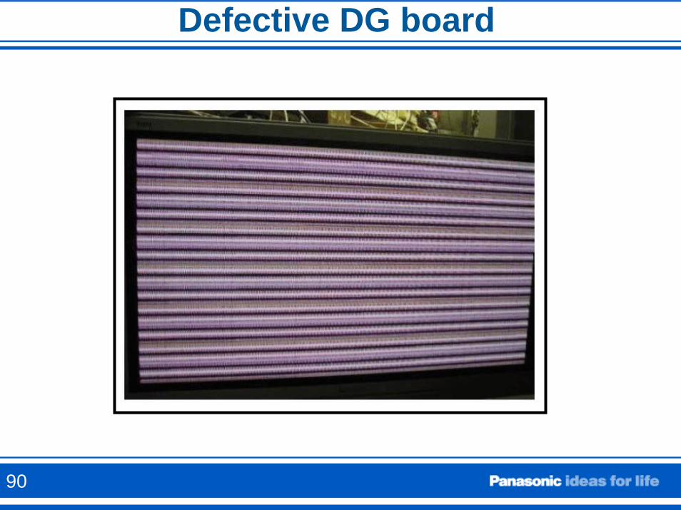
Defective DG board
90

ForumForumThank you for your participation
91