Embed Size (px)
Citation preview
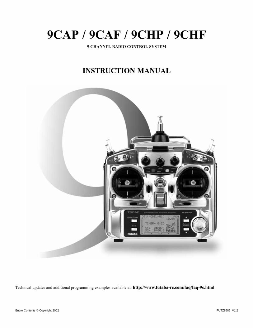
9CAP / 9CAF / 9CHP / 9CHF9 CHANNEL RADIO CONTROL SYSTEM
INSTRUCTION MANUAL
Technical updates and additional programming examples available at: http://www.futaba-rc.com/faq/faq-9c.html
FUTZ8585 V1.2Entire Contents © Copyright 2002
INTRODUCTION . . . . . . . . . . . . . . . . . . . . . . . . . . . . .3Additional Technical Help, Support and Service . . . . .3Application, Export and Modification . . . . . . . . . . . . .4Meaning of Special Markings . . . . . . . . . . . . . . . . . . .5Safety Precautions (do not operate without reading) . .5Introduction to the 9C . . . . . . . . . . . . . . . . . . . . . . . . .7Contents and Technical Specifications . . . . . . . . . . . .9Accessories . . . . . . . . . . . . . . . . . . . . . . . . . . . . . . .10Transmitter Controls & Switch Identification/Assignments . . . . . . . . . . . . . .11Charging the Ni-Cd Batteries . . . . . . . . . . . . . . . . . .14Stick Adjustments . . . . . . . . . . . . . . . . . . . . . . . . . . .15Adjusting display contrast . . . . . . . . . . . . . . . . . . . .15Changing mode . . . . . . . . . . . . . . . . . . . . . . . . . . . .15Radio Installation & Range Checking . . . . . . . . . . . .16Aircraft Frequencies . . . . . . . . . . . . . . . . . . . . . . . . .17Transmitter Displays and Buttons . . . . . . . . . . . . . . .18Warning and Error Displays . . . . . . . . . . . . . . . . . . .19
AIRPLANE (ACRO) FUNCTIONS . . . . . . . . . . . . . . . .20Map of Functions . . . . . . . . . . . . . . . . . . . . . . . . . . .21Quick Guide to Setting up a 4-channel Airplane . . . .22
ACRO BASIC MENU FUNCTIONS . . . . . . . . . . . . . . . .25MODEL Submenu: MODEL SELECT, COPY and NAME . .25PARAMETER Submenu: TYPE, MODUL, ATL, AIL2,& RESET . . . . . . . . . . . . . . . . . . . . . . . . . . . . . . . . . .28Servo REVERSE . . . . . . . . . . . . . . . . . . . . . . . . . . . . .31END POINT . . . . . . . . . . . . . . . . . . . . . . . . . . . . . . . .32Idle Management: IDLE DOWN and THR-CUT . . . . . . . .33Dual/Triple Rates and Exponential (D/R,EXP) . . . . . .35TIMER Submenu . . . . . . . . . . . . . . . . . . . . . . . . . . . .38Auxiliary Channel assignments and CH9 reverse (AUX-CH) . . . . . . . . . . . . . . . . . . . . . . . .39TRAINER . . . . . . . . . . . . . . . . . . . . . . . . . . . . . . . . . .40TRIM and SUB-TRIM . . . . . . . . . . . . . . . . . . . . . . . . . .41SERVO Display . . . . . . . . . . . . . . . . . . . . . . . . . . . . .42Fail Safe and Battery FailSafe (F/S) . . . . . . . . . . . . .43
ACRO ADVANCE MENU FUNCTIONS . . . . . . . . . . . . . .44Wing types . . . . . . . . . . . . . . . . . . . . . . . . . . . . . . . .44
FLAPERON . . . . . . . . . . . . . . . . . . . . . . . . . . . . . .45FLAP TRIM . . . . . . . . . . . . . . . . . . . . . . . . . . . . . .46Aileron Differential (AIL-DIFF) . . . . . . . . . . . . . . .47Using a 5-channel receiver: AIL-2 . . . . . . . . . . . . .47ELEVON (see tail types) . . . . . . . . . . . . . . . . . . . . .48
Tail types . . . . . . . . . . . . . . . . . . . . . . . . . . . . . . . . .48ELEVON . . . . . . . . . . . . . . . . . . . . . . . . . . . . . . . .48Twin Elevator Servos (AILEVATOR) . . . . . . . . . . . .49V-TAIL . . . . . . . . . . . . . . . . . . . . . . . . . . . . . . . . . .50
SNAP ROLL . . . . . . . . . . . . . . . . . . . . . . . . . . . . . . . .51Mixes: definitions and types . . . . . . . . . . . . . . . . . . .53
ELEV-FLAP . . . . . . . . . . . . . . . . . . . . . . . . . . . . . .54AIRBRAKE/BUTTERFLY (crow) . . . . . . . . . . . . . . . .55THROTTLE-NEEDLE . . . . . . . . . . . . . . . . . . . . . . . . .56THROTTLE DELAY . . . . . . . . . . . . . . . . . . . . . . . . . .57Linear, Prog. mixes 1-5 . . . . . . . . . . . . . . . . . . . . .59Curve, Prog. mixes 6-7 . . . . . . . . . . . . . . . . . . . . .62
Other Equipment . . . . . . . . . . . . . . . . . . . . . . . . . . . . .64GLIDER (GLID1FLP/2FLP) FUNCTIONS . . . . . . . . . . .65
Table of contents . . . . . . . . . . . . . . . . . . . . . . . . . . .65Getting Started with a Basic 4-CH Glider . . . . . . . . .66GLIDER-SPECIFIC BASIC MENU FUNCTIONS . .68
Model type (PARAMETERS submenu) . . . . . . . . . .68GLIDER-SPECIFIC ADVANCE MENU FUNCTIONS 69
BUTTERFLY . . . . . . . . . . . . . . . . . . . . . . . . . . . . . .69FLAP-AILE (GLID2FLP only) . . . . . . . . . . . . . . . . . .70AILE-FLAP (GLID2FLP only) . . . . . . . . . . . . . . . . . .70START OFS (Launch/Start Setup) . . . . . . . . . . . . . .71SPEED OFS (Minimum Drag Setup) . . . . . . . . . . .71
HELICOPTER (SW…) FUNCTIONS . . . . . . . . . . . . .73Table of contents and reference info for helicopters .73Getting Started with a Basic Helicopter . . . . . . . . . .74HELI-SPECIFIC BASIC MENU FUNCTIONS . . . . .77
MODEL TYPE (PARAMETERS submenu) . . . . . . . . . .77SWASH AFR (swashplate surface direction and travelcorrection) (not in SWH1) . . . . . . . . . . . . . . . . . .79Setting up the Normal Flight Condition . . . . . . .81THR-CUT (specialized settings for helicopter specificmodels) . . . . . . . . . . . . . . . . . . . . . . . . . . . . . . . .82
HELI-SPECIFIC ADVANCE MENU FUNCTIONS . . .83THROTTLE HOLD . . . . . . . . . . . . . . . . . . . . . . . . . .83THR-CURVE, PIT-CURVE and REVO. . . . . . . . . . . . . .84Idle-ups . . . . . . . . . . . . . . . . . . . . . . . . . . . . . . . .85Trims/offset . . . . . . . . . . . . . . . . . . . . . . . . . . . . .86Delay . . . . . . . . . . . . . . . . . . . . . . . . . . . . . . . . .87Hovering setups . . . . . . . . . . . . . . . . . . . . . . . . . .88Gyros and governors . . . . . . . . . . . . . . . . . . . . . .89
Glossary . . . . . . . . . . . . . . . . . . . . . . . . . . . . . . . . . . . .94
Note that in the text of this manual, beginning at this point,any time we are using a feature’s specialized name orabbreviation, as seen on the screen of the 9C, that name,feature, or abbreviation will be exactly as seen on the radio’sscreen, including capitalization and shown in a DIFFERENTTYPE STYLE for clarity. Any time we mention a specificcontrol on the radio itself, such as moving SWITCH A, KNOBVR(B), or the THROTTLE STICK, those words will bedisplayed as they are here.
2
TABLE OF CONTENTS

INTRODUCTION
Thank you for purchasing a Futaba® 9C series digital proportional R/C system. This system is extremely versatile and maybe used by beginners and pros alike. In order for you to make the best use of your system and to fly safely, please read thismanual carefully. If you have any difficulties while using your system, please consult the manual, our online FrequentlyAsked Questions (on the web pages referenced below), your hobby dealer, or the Futaba Service Center.
Owner’s Manual and Additional Technical HelpThis manual has been carefully written to be as helpful to you, the new owner, as possible. There are many pages of setupprocedures and examples. However, it need not be your sole resource of setup guidelines for your 9C. For example, pages22-24 include setup instructions for a basic 4-channel airplane. The Frequently Asked Questions web page referencedbelow includes this type of step-by-step setup instructions for a variety of other model types, including multi-engine,complex gear installation, 7-servo aerobatic models, 140 degree CCPM, etc.
Due to unforeseen changes in production procedures, the information contained in this manual is subject to change without notice.
Support and Service: It is recommended to have your Futaba equipment serviced annually during your hobby’s “offseason” to ensure safe operation.
IN NORTH AMERICA
Please feel free to contact the Futaba Service Center for assistance in operation, use and programming. Please be sure toregularly visit the 9C Frequently Asked Questions web site at www.futaba-rc.com\faq\faq-9c.html. This page includesextensive programming, use, set up and safety information on the 9C radio system and is updated regularly. Any technicalupdates and US manual corrections will be available on this web page. If you do not find the answers to your questions there,please see the end of our F.A.Q. area for information on contacting us via email for the most rapid and convenient response.
Don’t have Internet access? Internet access is available at no charge at most public libraries, schools, and other publicresources. We find internet support to be a fabulous reference for many modelers as items can be printed and saved for futurereference, and can be accessed at any hour of the day, night, weekend or holiday. If you do not wish to access the internet forinformation, however, don’t worry. Our support teams are available Monday through Friday 8-5 Central time to assist you.
FOR SERVICE ONLY: FOR SUPPORT :Futaba Service Center (PROGRAMMING AND USER QUESTIONS)1610 Interstate Drive Please start here for answers to most questions:Champaign IL 61822 www.futaba-rc.com\faq\faq-9c.html
www.hobbyservices.com FACSIMILE: 217-398-7721PHONE: 217-398-8970 option 4
OUTSIDE NORTH AMERICA
Please contact your Futaba importer in your region of the world to assist you with any questions, problems or service needs.
Please recognize that all information in this manual, and all support availability, is based upon the systems sold in NorthAmerica only. Products purchased elsewhere may vary. Always contact your region’s support center for assistance.
3
Application, Export, and Modification
1. This product may be used for model airplane or surface (boat, car, robot) use, if on the correct frequency. It is notintended for use in any application other than the control of models for hobby and recreational purposes. The product issubject to regulations of the Ministry of Radio/Telecommunications and is restricted under Japanese law to such purposes.
2. Exportation precautions:(a) When this product is exported from the country of manufacture, its use is to be approved by the laws governing thecountry of destination which govern devices that emit radio frequencies. If this product is then re-exported to othercountries, it may be subject to restrictions on such export. Prior approval of the appropriate government authorities maybe required. If you have purchased this product from an exporter outside your country, and not the authorized Futabadistributor in your country, please contact the seller immediately to determine if such export regulations have been met.
(b) Use of this product with other than models may be restricted by Export and Trade Control Regulations, and an applicationfor export approval must be submitted. In the US, use of 72MHz (aircraft only), 75MHz (ground models only) and 27MHz(both) frequency bands are strictly regulated by the FCC. This equipment must not be utilized to operate equipment other thanradio controlled models. Similarly, other frequencies (except 50MHz, for HAM operators) must not be used to operate models.
3. Modification, adjustment, and replacement of parts: Futaba is not responsible for unauthorized modification, adjustment, andreplacement of parts on this product. Any such changes may void the warranty.
The Following Statement Applies to the Receiver (for U.S.A.)
This device complies with part 15 of the FCC rules. Operation is subject to the following two conditions:
(1) This device may not cause harmful interference, and
(2) This device must accept any interference received, including interference that may cause undesirable operation.
The RBRC™ SEAL on the nickel-cadmium battery contained in Futaba products indicates that FutabaCorporation of America is voluntarily participating in an industry-wide program to collect and recycle thesebatteries at the end of their useful lives, when taken out of service within the United States. The RBRC™
program provides a convenient alternative to placing used nickel-cadmium batteries into the trash or municipalwaste system, which is illegal in some areas.
(for USA)
You may contact your local recycling center for information on where to return the spent battery. Please call 1-800-8-BATTERY for information on Ni-Cd battery recycling in your area. Futaba Corporation of America’s involvementin this program is part of its commitment to protecting our environment and conserving natural resources.
NOTE: Our instruction manuals encourage our customers to return spent batteries to a local recycling center in order tokeep a healthy environment.RBRC is a trademark of the Rechargeable Battery Recycling Corporation.
4
Meaning of Special MarkingsPay special attention to safety where indicated by the following marks:
DANGER - Procedures which may lead to dangerous conditions and cause death/serious injury if not carried out properly.
WARNING - Procedures which may lead to a dangerous condition or cause death or serious injury to the user if notcarried out properly, or procedures where the probability of superficial injury or physical damage is high.
CAUTION - Procedures where the possibility of serious injury to the user is small, but there is a danger of injury, orphysical damage, if not carried out properly.
= Prohibited = Mandatory
Warning: Always keep electrical components away from small children.
FLYING SAFETY
To ensure the safety of yourself and others, please observe the following precautions:
Have regular maintenance performed. Although your 9C protects the model memories with non-volatile EEPROMmemory (which does not require periodic replacement) and not a battery, it still should have regular checkups for wearand tear. We recommend sending your system to the Futaba Service Center annually during your non-flying-seasonfor a complete checkup and service.
Ni-Cd BatteryCharge the batteries! (See Charging the Ni-Cd batteries, p. 14, for details.) Always recharge the transmitter andreceiver batteries for at least 8 hours before each flying session. A low battery will soon die, causing loss of controland a crash. When you begin your flying session, reset your 9C’s built-in timer, and during the session pay attentionto the duration of usage.
Stop flying long before your batteries become low on charge. Do not rely on your radio’s low battery warningsystems, intended only as a precaution, to tell you when to recharge. Always check your transmitter andreceiver batteries prior to each flight.
Where to Fly
We recommend that you fly at a recognized model airplane flying field. You can find model clubs and fields by askingyour nearest hobby dealer, or in the US by contacting the Academy of Model Aeronautics.
You can also contact the national Academy of Model Aeronautics (AMA), which has more than 2,500 chartered clubs across thecountry. Through any one of them, instructor training programs and insured newcomer training are available. Contact the AMAat the address or toll-free phone number below.
Academy of Model Aeronautics5151 East Memorial DriveMuncie, IN 47302-9252
Tele. (800) 435-9262Fax (765) 741-0057
or via the Internet at http:\\www.modelaircraft.org
5
Always pay particular attention to the flying field’s rules, as well as the presence and location of spectators, thewind direction, and any obstacles on the field. Be very careful flying in areas near power lines, tall buildings, orcommunication facilities as there may be radio interference in their vicinity.
If you must fly away from a club field, be sure there are no other modelers flying within a three-to-five-mile range, or you maylose control of your aircraft or cause someone else to lose control.
At the flying field
Before flying, be sure that the frequency you intend to fly with is not in use, and secure any frequency controldevice (pin, tag, etc.) for that frequency before turning on your transmitter. It is never possible to fly two or moremodels on the same frequency at the same time. Even though there are different types of modulation (AM, FM,PCM), only one model may be flown on a single frequency at any one time.
To prevent possible damage to your radio gear, turn the power switches on and off in the proper sequence:
1. Pull throttle stick to idle position, or otherwise disarm your motor/engine.2. Turn on the transmitter power and allow your transmitter to reach its home screen.3. Confirm the proper model memory has been selected.4. Fully extend the transmitter antenna.5. Turn on your receiver power.6. Test all controls. If a servo operates abnormally, don’t attempt to fly until you determine the cause of the problem.
(For PCM systems only: Test to ensure that the FailSafe settings are correct by waiting at least 2 minutes afteradjusting then, turning the transmitter off and confirming the proper surface/throttle movements. Turn the transmitterback on.)
7. Start your engine.8. Complete a full range check (see p. 17).9. After flying, bring your throttle stick to idle position, engage any kill switches or otherwise disarm your motor/engine.
10. Turn off receiver power.11. Turn off transmitter power.
If you do not turn on your system in this order, you may damage your servos or control surfaces, flood your engine, or in thecase of electric-powered or gasoline-powered models, the engine may unexpectedly turn on and cause a severe injury.
While you are getting ready to fly, if you place your transmitter on the ground, be sure that the wind won’t tipit over. If it is knocked over, the throttle stick may be accidentally moved, causing the engine to speed up. Also,damage to your transmitter may occur.
Before taxiing, be sure to extend the transmitter antenna to its full length.
A collapsed antenna will reduce your flying range and cause a loss of control. It is a good idea to avoid pointing the transmitterantenna directly at the model, since the signal is weakest in that direction.
Don’t fly in the rain! Water or moisture may enter the transmitter through the antenna or stick openings and cause erraticoperation or loss of control. If you must fly in wet weather during a contest, be sure to cover your transmitter with a plasticbag or waterproof barrier. Never fly if lightning is expected.
6
A QUICK INTRODUCTION TO THE 9C SYSTEM
TRANSMITTER:
• Large graphic liquid-crystal display panel with 4 buttons and an easy set up turn-and-press Dial for quick, easy setup.
•All transmitters include all 3 aircraft types with specialized programming for each, including:• Airplane (ACRO)
• V-tail • Twin Aileron Servos (FLAPERON and AIL-DIFF)• ELEVON • Twin Elevator Servos (AILEVATOR)• AIRBRAKE • Snap Roll (4 separate directions available)
• Helicopter (5 swashplate types, including CCPM, see page 77)(HELI)• 3 Idle Ups • Throttle and Pitch Curves per Condition• Revo. Mixing • Gyro Mixing including Separate Settings per Condition• Delay • Governor Mixing
• Sailplane/Glider (2 wing types)(GLID)• V-tail • Twin Ailerons (FLAPERON and AIL-DIFF)• ELEVON • Crow (BUTTERFLY)• START OFFSET • SPEED OFFSET
• BASIC menu for quick, easy set up of less complex models.
• ADVANCE menu for more complex, unique setups.
• Four electronic TRIM LEVERS for rapid yet precise trim adjustment - no remembering to “store trims” between modelsand no more “bumped trims” during transport.
• IDLE- DOWN (ACRO) and THR-CUT (ACRO/HELI) (engine shut off) setups to allow precise engine control for taxi and landings.
• 8 complete model memories with 6 more per optional CAMPac.
• New stick design with improved feel, adjustable length and tension.
• Triple rates available by setting dual rates to 3-position switches.
• Eight SWITCHES, 3 DIALS and 2 SLIDERS; completely assignable in most applications.
• Trainer system includes the “functional” (FUNC) setting, which allows the student to use the 9C’s mixing, helicopter, andother programming functions even with a 4-channel buddy box. (Optional trainer cord required.)
• Transmits in both FM (PPM) and PCM by selecting modulation/cycling transmitter. Requires receiver of proper modulation.
• Permanent memory storage via EEPROM with no backup battery to service or have fail.
• 9CA transmitter features airplane friendly switch layout, with the trainer switch at the left hand, and a notched throttleto minimize throttle changes with rudder input. Defaults to ACRO MODEL TYPE.
• 9CH transmitter features helicopter-friendly switch layout, with idle-up and throttle hold switches at the left hand, anda smooth, ratchet-less (unsprung) throttle for perfect hovering. Defaults to HELI(SW1) MODEL TYPE.
• Change transmitter mode from mode 2 to modes 1, 3, or 4. (See P. 15)
Note that in the text of this manual, beginning at this point, any time we are using a feature’s specialized name or abbreviationas seen on the screen of the 9C, that name, feature, or abbreviation will be exactly as seen on the radio’s screen, includingcapitalization and shown in a DIFFERENT TYPE STYLE for clarity. Any time we mention a specific control on the radio itself,such as moving SWITCH A, KNOB VR(B), or the THROTTLE STICK, those words will be displayed as they are here.
7
MODULE: 72TP-FM
• Module may be easily removed and a module on a different channel (or even band) reinserted to change the frequencyon which the 9C transmits.
• Module transmits both FM (PPM) and PCM. No need for a second module.
• All transmission circuitry is included in the module, so no retuning is needed when changing channels or even bands.
• Frequency band is changed by inserting a module on the proper band, including for international or ground model use.
• In North America it is against FCC regulation to change the crystal within the transmitter module to a differentchannel. All such transmitter crystal changes must be performed by a certified radio technician. Failure to properly tunea system to its new channel may result in decreased range and may also result in interference to other types of frequencyusers on adjoining channels. Doing so also voids your AMA insurance.
• The FSS synthesized module for the 9Z family of radios is NOT compatible with the 9C.
• Radio system beeps and RF LIGHT goes out to indicate module is not installed and radio is not transmitting.
• Non-Futaba brand modules are not FCC certified for use with this radio and therefore are against FCC regulation to use.Doing so also voids your AMA insurance.
• TJ75FM modules may also be used with the 9C for ground use models such as robotics, rocketry, trains, cars, and boats.
RECEIVER: R138/R148/R149
• The R138 or R148 FM 8-channel or the R149 PCM 9-channel receiver included with your system is a high-sensitivitynarrow-band dual-conversion receiver.
• Note that your 9C transmitter is capable of transmission on both PPM (FM) and PCM with just a simple programmingchange and just turning the transmitter off and back on. (See p. 28.)
• Any Futaba narrow band FM receiver (all produced after 1991) on the correct frequency band and frequency may beused with the 9C.
• Any Futaba PCM 1024 receiver on the right frequency band and frequency may be used with the 9C (all 1024 receiverssay PCM1024; receivers which say PCM but not 1024 are 512 resolution and not compatible).
NEVER attempt to change a receiver’s band by simply changing crystal (IE removing a 72MHz crystal and insertinga 75MHz crystal). A receiver that has a crystal installed from a different frequency band without retuning will notreceive properly and will have dramatically decreased range.
• In North America the receiver included with this system may have its frequency changed by simply changing the crystalas long as it remains in the same half the band. A low band receiver between channels 11 and 35 may be changed toany other channel between 11 and 35 without requiring any tuning. A high band receiver between channels 36 and 60may similarly be changed. Receivers being changed from a high band channel to a low band or vice versa require propertuning and service by the Futaba Service Center.
SERVOS
• Please see technical specifications page for specifics on the servos included with your system.
• The included receiver is compatible with all J-plug Futaba servos, including retract, winch, and digital servos.
8
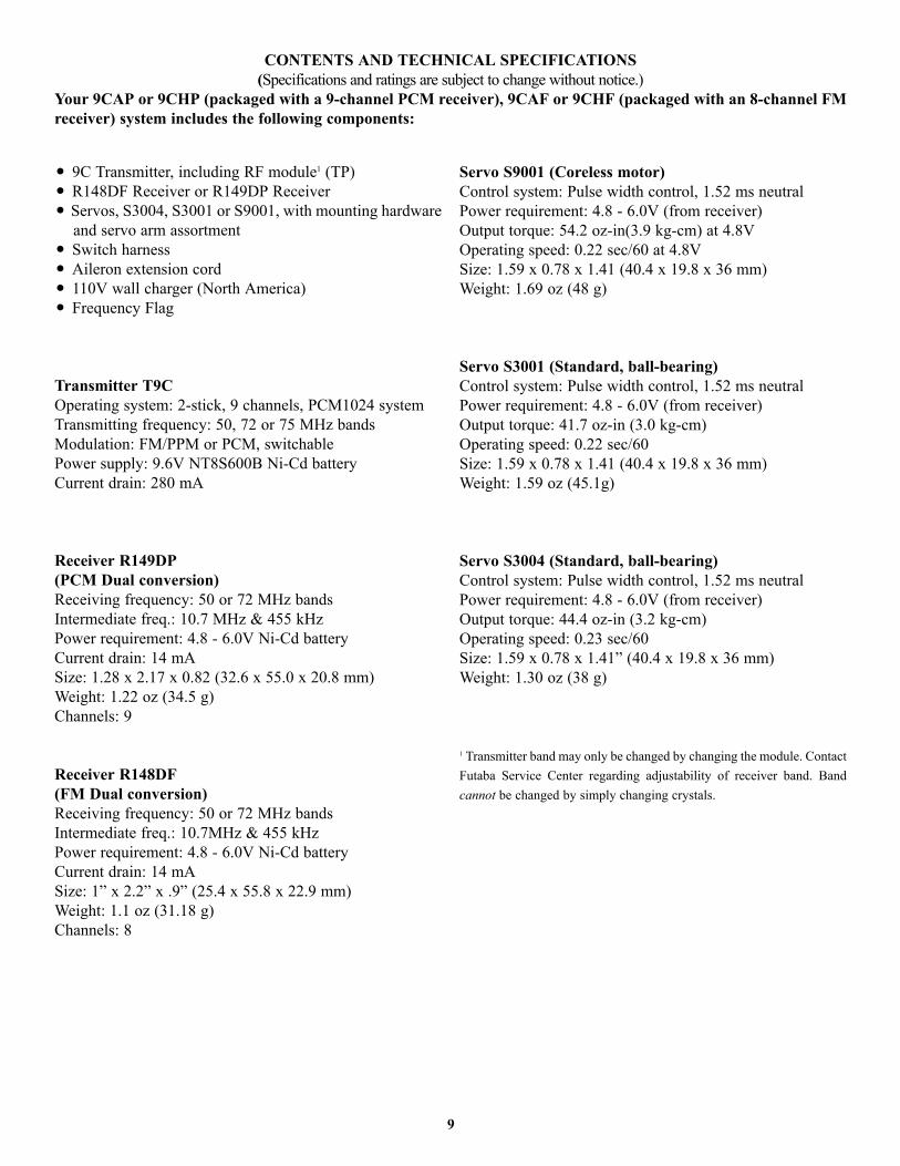
• 9C Transmitter, including RF module1 (TP)• R148DF Receiver or R149DP Receiver • Servos, S3004, S3001 or S9001, with mounting hardware
and servo arm assortment• Switch harness• Aileron extension cord• 110V wall charger (North America)• Frequency Flag
Transmitter T9C Operating system: 2-stick, 9 channels, PCM1024 systemTransmitting frequency: 50, 72 or 75 MHz bandsModulation: FM/PPM or PCM, switchablePower supply: 9.6V NT8S600B Ni-Cd batteryCurrent drain: 280 mA
Receiver R149DP (PCM Dual conversion)Receiving frequency: 50 or 72 MHz bandsIntermediate freq.: 10.7 MHz & 455 kHzPower requirement: 4.8 - 6.0V Ni-Cd batteryCurrent drain: 14 mASize: 1.28 x 2.17 x 0.82 (32.6 x 55.0 x 20.8 mm)Weight: 1.22 oz (34.5 g)Channels: 9
Receiver R148DF (FM Dual conversion)Receiving frequency: 50 or 72 MHz bandsIntermediate freq.: 10.7MHz & 455 kHzPower requirement: 4.8 - 6.0V Ni-Cd batteryCurrent drain: 14 mASize: 1” x 2.2” x .9” (25.4 x 55.8 x 22.9 mm)Weight: 1.1 oz (31.18 g)Channels: 8
Servo S9001 (Coreless motor)Control system: Pulse width control, 1.52 ms neutralPower requirement: 4.8 - 6.0V (from receiver)Output torque: 54.2 oz-in(3.9 kg-cm) at 4.8VOperating speed: 0.22 sec/60 at 4.8VSize: 1.59 x 0.78 x 1.41 (40.4 x 19.8 x 36 mm)Weight: 1.69 oz (48 g)
Servo S3001 (Standard, ball-bearing)Control system: Pulse width control, 1.52 ms neutralPower requirement: 4.8 - 6.0V (from receiver)Output torque: 41.7 oz-in (3.0 kg-cm)Operating speed: 0.22 sec/60Size: 1.59 x 0.78 x 1.41 (40.4 x 19.8 x 36 mm)Weight: 1.59 oz (45.1g)
Servo S3004 (Standard, ball-bearing)Control system: Pulse width control, 1.52 ms neutralPower requirement: 4.8 - 6.0V (from receiver)Output torque: 44.4 oz-in (3.2 kg-cm)Operating speed: 0.23 sec/60Size: 1.59 x 0.78 x 1.41” (40.4 x 19.8 x 36 mm)Weight: 1.30 oz (38 g)
1 Transmitter band may only be changed by changing the module. ContactFutaba Service Center regarding adjustability of receiver band. Bandcannot be changed by simply changing crystals.
9
CONTENTS AND TECHNICAL SPECIFICATIONS(Specifications and ratings are subject to change without notice.)
Your 9CAP or 9CHP (packaged with a 9-channel PCM receiver), 9CAF or 9CHF (packaged with an 8-channel FMreceiver) system includes the following components:
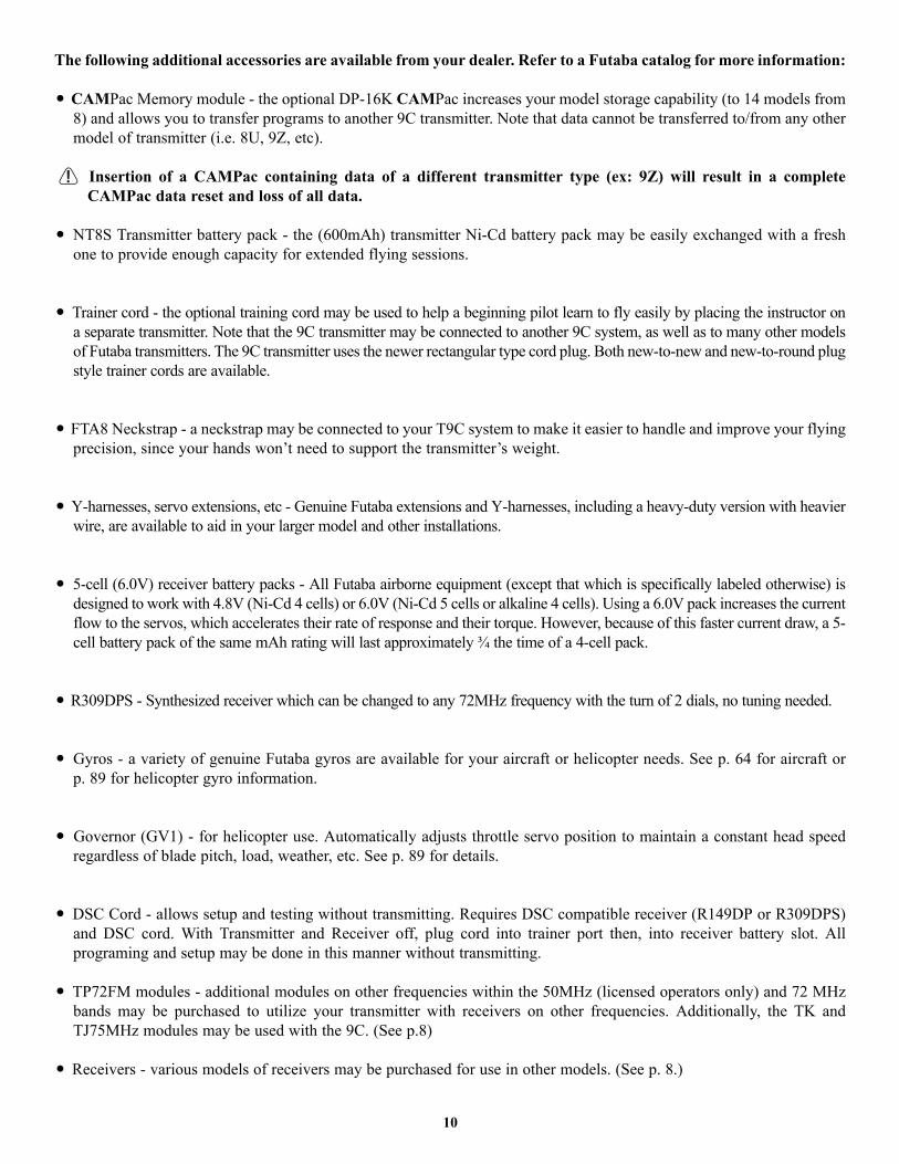
The following additional accessories are available from your dealer. Refer to a Futaba catalog for more information:
• CAMPac Memory module - the optional DP-16K CAMPac increases your model storage capability (to 14 models from8) and allows you to transfer programs to another 9C transmitter. Note that data cannot be transferred to/from any othermodel of transmitter (i.e. 8U, 9Z, etc).
Insertion of a CAMPac containing data of a different transmitter type (ex: 9Z) will result in a completeCAMPac data reset and loss of all data.
• NT8S Transmitter battery pack - the (600mAh) transmitter Ni-Cd battery pack may be easily exchanged with a freshone to provide enough capacity for extended flying sessions.
• Trainer cord - the optional training cord may be used to help a beginning pilot learn to fly easily by placing the instructor ona separate transmitter. Note that the 9C transmitter may be connected to another 9C system, as well as to many other modelsof Futaba transmitters. The 9C transmitter uses the newer rectangular type cord plug. Both new-to-new and new-to-round plugstyle trainer cords are available.
• FTA8 Neckstrap - a neckstrap may be connected to your T9C system to make it easier to handle and improve your flyingprecision, since your hands won’t need to support the transmitter’s weight.
• Y-harnesses, servo extensions, etc - Genuine Futaba extensions and Y-harnesses, including a heavy-duty version with heavierwire, are available to aid in your larger model and other installations.
• 5-cell (6.0V) receiver battery packs - All Futaba airborne equipment (except that which is specifically labeled otherwise) isdesigned to work with 4.8V (Ni-Cd 4 cells) or 6.0V (Ni-Cd 5 cells or alkaline 4 cells). Using a 6.0V pack increases the currentflow to the servos, which accelerates their rate of response and their torque. However, because of this faster current draw, a 5-cell battery pack of the same mAh rating will last approximately ¾ the time of a 4-cell pack.
• R309DPS - Synthesized receiver which can be changed to any 72MHz frequency with the turn of 2 dials, no tuning needed.
• Gyros - a variety of genuine Futaba gyros are available for your aircraft or helicopter needs. See p. 64 for aircraft or p. 89 for helicopter gyro information.
• Governor (GV1) - for helicopter use. Automatically adjusts throttle servo position to maintain a constant head speedregardless of blade pitch, load, weather, etc. See p. 89 for details.
• DSC Cord - allows setup and testing without transmitting. Requires DSC compatible receiver (R149DP or R309DPS)and DSC cord. With Transmitter and Receiver off, plug cord into trainer port then, into receiver battery slot. Allprograming and setup may be done in this manner without transmitting.
• TP72FM modules - additional modules on other frequencies within the 50MHz (licensed operators only) and 72 MHzbands may be purchased to utilize your transmitter with receivers on other frequencies. Additionally, the TK andTJ75MHz modules may be used with the 9C. (See p.8)
• Receivers - various models of receivers may be purchased for use in other models. (See p. 8.)
10

TRANSMITTER CONTROLS – AIRPLANE
SW(B)
VR(A)VR(B)
SW(A)
SW(F)
SW(E)
VR(D) VR(E)
VR(C)
SW(G)SW(H)
SW(D)
SW(C)
Dust Cap(optional CAMPac module plugs in here)
CH8 Knob
This controls CH6, and if flaperon mixing is activated controls the flap.
Flap Trim Control
Rudder Dual Rate Switch
Elevator Dual RateSwitch
Snap Roll or Trainer Switch
Landing GearSwitch/CH5
Rudder/Throttle
Stick
PowerLED*
ThrottleTrim Lever
RudderTrim Lever
LCD Panel
Power Switch(Up position: ON)
Hook(for optional neckstrap)
Edit Keys Edit keys
Aileron Trim Lever
Dial
Elevator Trim Lever
Elevator/Aileron
Stick
Aileron Dual Rate Switch
Elevator - Flap Mixing or Airbrake Mixing Switch
Spoiler/CH7 ControlThis knob is disabled if aileron differential is activated.
Carrying Handle
Antenna
Antenna must be fully extended when flying.
Be careful not to bend your antenna when you collapse or extend it.
LED**RF
11
This figure shows the default switch assignments for a Mode 2 system as supplied by the factory.You can change many of the switch positions or functions by selecting a new position within
the setting menu for the function you wish to move. (Example: move aileron dual rates to switch Cto create triple rates. See p. 35 for details.)
* Power LED blinks to indicate if any mix switches are activated.** RF LED is green when the transmission link is solid and the radio is transmitting properly.
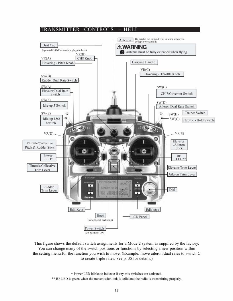
TRANSMITTER CONTROLS – HELI
SW(B)
VR(A)VR(B)
SW(A)
SW(F)
SW(E)
VR(D) VR(E)
VR(C)
SW(G)SW(H)
SW(D)
SW(C)
Dust Cap(optional CAMPac module plugs in here)
CH8 KnobHovering - Pitch Knob
Rudder Dual Rate Switch
Elevator Dual RateSwitch
Idle-up 3 Switch
Idle-up 1&2Switch
Throttle/CollectivePitch & Rudder Stick
Throttle/CollectiveTrim Lever
PowerLED*
RudderTrim Lever
LCD Panel
Power Switch(Up position: ON)
Hook(for optional neckstrap)
Edit Keys Edit keys
Aileron Trim Lever
Dial
Elevator Trim Lever
Elevator/Aileron
Stick
Aileron Dual Rate Switch
Throttle - Hold Switch
Trainer Switch
CH 7/Governor Switch
Hovering - Throttle Knob
Carrying Handle
Antenna
Antenna must be fully extended when flying.
Be careful not to bend your antenna when you collapse or extend it.
LED**RF
12
This figure shows the default switch assignments for a Mode 2 system as supplied by the factory.You can change many of the switch positions or functions by selecting a new position within
the setting menu for the function you wish to move. (Example: move aileron dual rates to switch Cto create triple rates. See p. 35 for details.)
* Power LED blinks to indicate if any mix switches are activated.** RF LED is green when the transmission link is solid and the radio is transmitting properly.

13
PUSH
Ni-Cd battery pack
Charging jack
Battery cover
Battery connector location
Trainer function/DSC function connector
RF module
To remove, press the tabs together and gently pull rearwards.To install, line up the connector pins withthe socket in the rear of the module andgently snap into position.
Switch/Knob Airplane (ACRO) Sailplane/Glider (GLID) Helicopter (HELI)A or H Tx.SWITCH A elevator dual rate elevator dual rate elevator dual rate
down = butterfly onSwitch B rudder dual rate rudder dual rate rudder dual rateSwitch C up = ELE-FLP on up = ELE-FLP on governor/ch 7
center/down = IDLE-DOWN center/down = IDLE-DOWNdown = AIRBRAKE on
SWITCH D aileron dual rate aileron dual rate aileron dual rate Switch E OR G* landing gear/ch 5 GLID1FLP = gear throttle hold Switch F OF H* snap roll/trainer trainer trainer/THR-CUTSWITCH G OR E* none back = SPEED OFFSET idle-up 1 and 2
fwd = START OFFSETSWITCH H OR F* none none idle-up3/ch 5/gyroKNOB A flap/ch 6 GLID1FLP: flap HOVERING PITCH
(flap trim if FLAPERON on) (flap trim if FLAPERON on)GLID2FLP: camber(flap trim if FL-AIL off)
KNOB B ch 8 ch 8 ch 8KNOB C spoiler/ch 7 spoiler/ch 7 HOVERING THROTTLE
(disabled if AIL-DIFF on) (disabled if AIL-DIF on)SLIDER D none GLID1FLP: ch 5 noneSLIDER E none none none
*On the 9CH transmitters, the TOP LEFT SWITCHES are spring-loaded and 3-position; on the 9CA, those switches are on the right side. For consistency,the switch position’s designation remains the same (upper left is F, etc), but the functions are moved to match the switch type.
NOTE: If you need to remove or replace the transmitter battery, do not pull on its wires to remove it. Instead,gently pull on the connector's plastic housing where it plugs into the transmitter.
SWITCH ASSIGNMENT TABLE
• The factory default functions activated by the switches and knobs for a Mode 2 transmitter are shown below. • Most 9C functions may be reassigned to non-default positions quickly and easily.• Basic control assignments of channels 5-9 are quickly adjustable in AUX-CH (see pp. 39). For example, the channel 5
servo, which defaults to SWITCH E for retract use, can easily be unassigned (NULL) to allow for easy use as a secondrudder servo in a mix, or to a slider or dial for bomb door or other control.
• Note that most functions need to be activated in the programming to operate.• Mode 1 transmitter functions are similar but reverse certain switch commands. Always check that you have the desired
switch assignment for each function during set up.
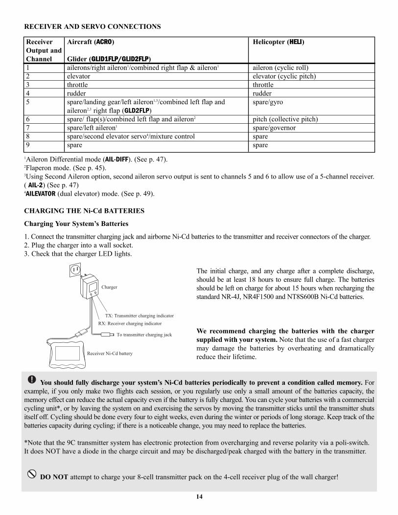
Receiver Aircraft (AACCRROO) Helicopter (HHEELLII)Output andChannel Glider (GGLLIIDD11FFLLPP//GGLLIIDD22FFLLPP)1 ailerons/right aileron1/combined right flap & aileron1 aileron (cyclic roll)2 elevator elevator (cyclic pitch)3 throttle throttle4 rudder rudder5 spare/landing gear/left aileron1,3/combined left flap and spare/gyro
aileron2,3 right flap (GLD2FLP)6 spare/ flap(s)/combined left flap and aileron2 pitch (collective pitch)7 spare/left aileron1 spare/governor8 spare/second elevator servo4/mixture control spare9 spare spare
14
1Aileron Differential mode (AIL-DIFF). (See p. 47).2Flaperon mode. (See p. 45).3Using Second Aileron option, second aileron servo output is sent to channels 5 and 6 to allow use of a 5-channel receiver.( AIL-2) (See p. 47)4AILEVATOR (dual elevator) mode. (See p. 49).
CHARGING THE Ni-Cd BATTERIES
Charging Your System’s Batteries
1. Connect the transmitter charging jack and airborne Ni-Cd batteries to the transmitter and receiver connectors of the charger.2. Plug the charger into a wall socket.3. Check that the charger LED lights.
The initial charge, and any charge after a complete discharge,should be at least 18 hours to ensure full charge. The batteriesshould be left on charge for about 15 hours when recharging thestandard NR-4J, NR4F1500 and NT8S600B Ni-Cd batteries.
We recommend charging the batteries with the chargersupplied with your system. Note that the use of a fast chargermay damage the batteries by overheating and dramaticallyreduce their lifetime.
You should fully discharge your system’s Ni-Cd batteries periodically to prevent a condition called memory. Forexample, if you only make two flights each session, or you regularly use only a small amount of the batteries capacity, thememory effect can reduce the actual capacity even if the battery is fully charged. You can cycle your batteries with a commercialcycling unit*, or by leaving the system on and exercising the servos by moving the transmitter sticks until the transmitter shutsitself off. Cycling should be done every four to eight weeks, even during the winter or periods of long storage. Keep track of thebatteries capacity during cycling; if there is a noticeable change, you may need to replace the batteries.
*Note that the 9C transmitter system has electronic protection from overcharging and reverse polarity via a poli-switch.It does NOT have a diode in the charge circuit and may be discharged/peak charged with the battery in the transmitter.
DO NOT attempt to charge your 8-cell transmitter pack on the 4-cell receiver plug of the wall charger!
Charger
TX: Transmitter charging indicatorRX: Receiver charging indicator
To transmitter charging jack
Receiver Ni-Cd battery
RECEIVER AND SERVO CONNECTIONS
15
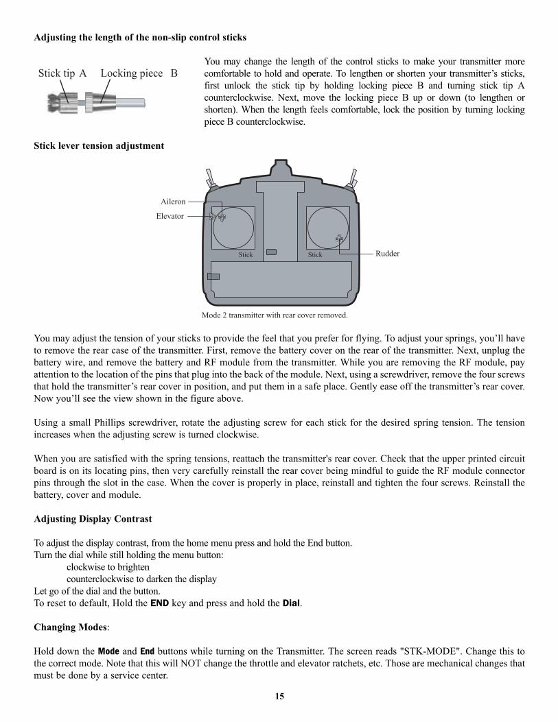
Adjusting the length of the non-slip control sticks
You may change the length of the control sticks to make your transmitter morecomfortable to hold and operate. To lengthen or shorten your transmitter’s sticks,first unlock the stick tip by holding locking piece B and turning stick tip Acounterclockwise. Next, move the locking piece B up or down (to lengthen orshorten). When the length feels comfortable, lock the position by turning lockingpiece B counterclockwise.
Stick lever tension adjustment
You may adjust the tension of your sticks to provide the feel that you prefer for flying. To adjust your springs, you’ll haveto remove the rear case of the transmitter. First, remove the battery cover on the rear of the transmitter. Next, unplug thebattery wire, and remove the battery and RF module from the transmitter. While you are removing the RF module, payattention to the location of the pins that plug into the back of the module. Next, using a screwdriver, remove the four screwsthat hold the transmitter’s rear cover in position, and put them in a safe place. Gently ease off the transmitter’s rear cover.Now you’ll see the view shown in the figure above.
Using a small Phillips screwdriver, rotate the adjusting screw for each stick for the desired spring tension. The tensionincreases when the adjusting screw is turned clockwise.
When you are satisfied with the spring tensions, reattach the transmitter's rear cover. Check that the upper printed circuitboard is on its locating pins, then very carefully reinstall the rear cover being mindful to guide the RF module connectorpins through the slot in the case. When the cover is properly in place, reinstall and tighten the four screws. Reinstall thebattery, cover and module.
Adjusting Display Contrast
To adjust the display contrast, from the home menu press and hold the End button. Turn the dial while still holding the menu button:
clockwise to brighten counterclockwise to darken the display
Let go of the dial and the button.To reset to default, Hold the END key and press and hold the Dial.
Changing Modes:
Hold down the Mode and End buttons while turning on the Transmitter. The screen reads "STK-MODE". Change this tothe correct mode. Note that this will NOT change the throttle and elevator ratchets, etc. Those are mechanical changes thatmust be done by a service center.
Aileron
Elevator
RudderStick Stick
Mode 2 transmitter with rear cover removed.
Stick tip A Locking piece B

RADIO INSTALLATION
While you are installing the battery, receiver, switch harness and servos into your model’s fuselage, please pay attention tothe following guidelines:
Use the supplied rubber grommets when you mount each servo. Be sure not toover-tighten the screws. If any portion of the servo case directly contacts the fuselage orthe servo rails, the rubber grommets will not dampen the vibration, which can causemechanical wear and servo failure.
Servo Throw
Once you have installed the servos, operate each one over its full travel and check that the pushrod and outputarms do not bind or collide with each other, even at extreme trim settings. Check to see that each control linkage doesnot require undue force to move (if you hear a servo buzzing when there is no transmitter control motion, most likely thereis too much friction in the control or pushrod). Even though the servo will tolerate loads, any unnecessary load applied tothe servo arm will drain the battery pack quickly.
Switch Harness Installation
When you are ready to install the switch harness, remove the switch cover and use it as a template to cut screw holesand a rectangular hole slightly larger than the full stroke of the switch. Choose a switch location on the opposite side ofthe fuselage from the engine exhaust pipe, and pick a location where it can’t be inadvertently turned on or off duringhandling or storage. Install the switch so it moves without restriction and snaps from ON to OFF and vice versa.
Receiver AntennaIt is normal for the receiver antenna to be longer than the fuselage.DO NOT cut or fold it back on itself — cutting or folding changes the electrical length of the antenna and may
reduce range. Secure the antenna to the top of the vertical fin, and let the excess wire length trail behind. You may run theantenna inside of a non-metallic housing within the fuselage, but range may suffer if the antenna is located near metal orcarbon fiber pushrods or cables. Be sure to perform a range check before flying.
Receiver Notes
When you insert servo, switch or battery connectors into the receiver, note that each plastic housing has analignment tab. Be sure the alignment tab is oriented properly before inserting the connector. To remove a connectorfrom the receiver, pull on the connector housing rather than the wires.
If your aileron servo (or others) are too far away to plug into the receiver, use an aileron extension cord to extend the lengthof the servo lead. Additional Futaba extension cords of varying lengths are available from your hobby dealer. Always use anextension of the proper length. Avoid plugging multiple extensions together to attain your desired length. If distance is greater than18” or multiple or high current draw servos are being used, use Futaba Heavy-Duty servo extensions.
Receiver Vibration and WaterproofingThe receiver contains precision electronic parts. Be sure to avoid vibration, shock, and temperature extremes.For protection, wrap the receiver in foam rubber or other vibration-absorbing materials. It is also a good idea
to waterproof the receiver by placing it in a plastic bag and securing the open end of the bag with a rubber band beforewrapping it with foam rubber. If you accidentally get moisture or fuel inside the receiver, you may experience intermittentoperation or a crash. If in doubt, send the receiver for service.
Wood screw
Rubber grommet
Brass eyelet
Servo mountor rail
16
Range Testing Your R/C System
Please note that different systems demonstrate different range checks and the same system will range check differently in differentconditions. Also, the receiver antenna's installation affects the range test -- exiting the top of the model is ideal.
This is a brief explanation of range test. For more in-depth specifics on receiver antenna mounting, additional checks ifunsatisfactory rage is demonstrated, range checking with gasoline powered engines, etc, please see our F.A.Q. page atwww.futaba-rc.com.
• Leave the transmitter's antenna retracted and be sure both batteries are fully charged.• Position the aircraft away from wires, other transmitters, etc.
Test one - engine/motor off, minimum of 100 ft. range• Have a friend view the model but not hold it, engine off. (People conduct signals, too!)• Walk away from the model, working all controls constantly. Stop when the servos jitter significantly (a jitter here and
there is normal), control movement stops (PCM), or you lose control altogether.• Measure the distance. If greater than 100 feet, great! Proceed to Test 2. Less than 100 feet of range check means you
need more information to determine if your system is safe to fly. Please see our web site or call support for additionaltests to perform before flying your system.
• Repeat with friend holding the model. Note any differences.Test two - engine/motor on
• Repeat the test with the model's engine running and with someone holding the model. If a decrease of more than 10%is noted, research and resolve the cause of interference prior to flying your model.
What your fully operational system demonstrates is the normal range for your system in those conditions. Before every flyingsession, it is critical that you perform a range check. It is also required by the AMA Safety Code. If you notice a significantdecrease in range with fully charged batteries, do not attempt to fly.
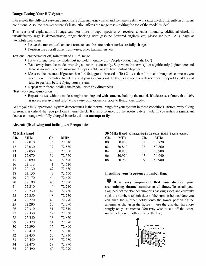
Aircraft (fixed wing and helicopter) Frequencies
17
72 MHz bandCh. MHz Ch. MHz11 72.010 36 72.51012 72.030 37 72.53013 72.050 38 72.55014 72.070 39 72.57015 72.090 40 72.59016 72.110 41 72.61017 72.130 42 72.63018 72.150 43 72.65019 72.170 44 72.67020 72.190 45 72.69021 72.210 46 72.71022 72.230 47 72.73023 72.250 48 72.75024 72.270 49 72.77025 72.290 50 72.79026 72.310 51 72.81027 72.330 52 72.83028 72.350 53 72.85029 72.370 54 72.87030 72.390 55 72.89031 72.410 56 72.91032 72.430 57 72.93033 72.450 58 72.95034 72.470 59 72.97035 72.490 60 72.990
50 MHz Band (Amateur Radio Operator “HAM” license required)Ch. MHz Ch. MHz00 50.800 01 50.82002 50.840 03 50.86004 50.880 05 50.90006 50.920 07 50.94008 50.960 09 50.980
Installing your frequency number flag:
It is very important that you display yourtransmitting channel number at all times. To install yourflag, peel off the channel number’s backing sheet, and carefullystick the numbers to both sides of the number holder. Now youcan snap the number holder onto the lower portion of theantenna as shown in the figure — use the clip that fits moresnugly on your antenna. You may wish to cut off the other,unused clip on the other side of the flag.
The following frequencies and channel numbers may be used for flying aircraft in the United States:TRANSMITTER DISPLAYS & BUTTONS
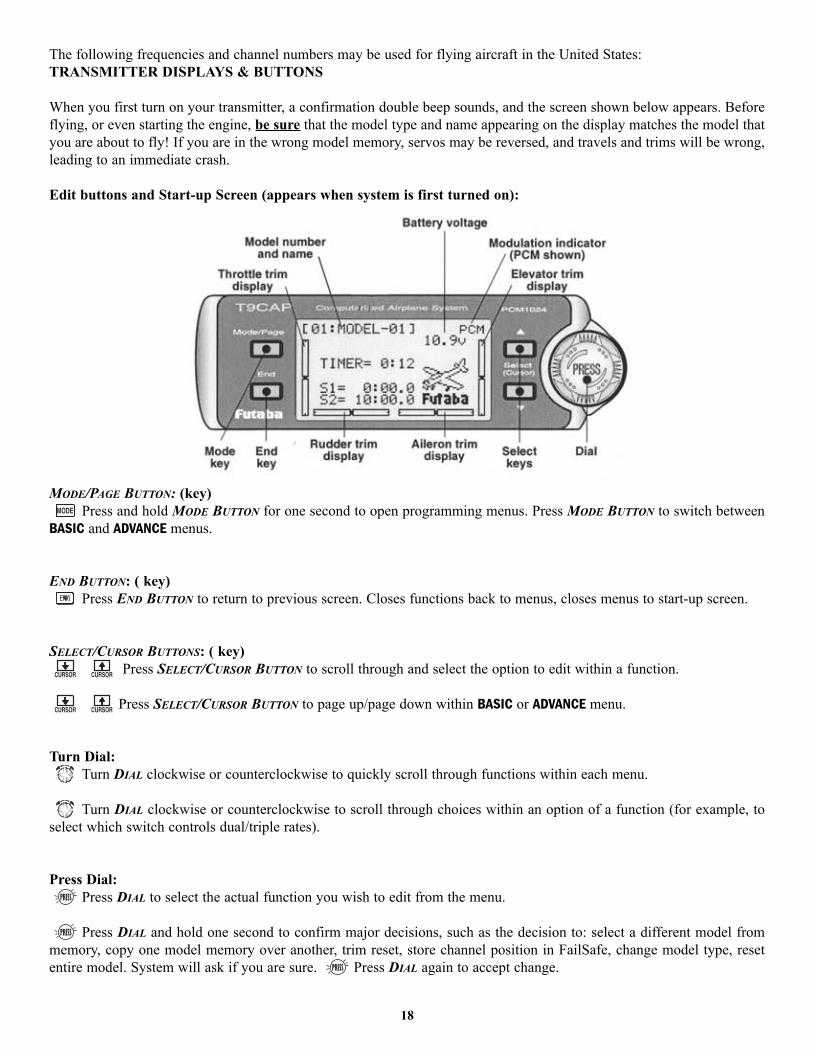
When you first turn on your transmitter, a confirmation double beep sounds, and the screen shown below appears. Beforeflying, or even starting the engine, be sure that the model type and name appearing on the display matches the model thatyou are about to fly! If you are in the wrong model memory, servos may be reversed, and travels and trims will be wrong,leading to an immediate crash.
Edit buttons and Start-up Screen (appears when system is first turned on):
MODE/PAGE BUTTON: (key)Press and hold MODE BUTTON for one second to open programming menus. Press MODE BUTTON to switch between
BASIC and ADVANCE menus.
END BUTTON: ( key)Press END BUTTON to return to previous screen. Closes functions back to menus, closes menus to start-up screen.
SELECT/CURSOR BUTTONS: ( key)Press SELECT/CURSOR BUTTON to scroll through and select the option to edit within a function.
Press SELECT/CURSOR BUTTON to page up/page down within BASIC or ADVANCE menu.
Turn Dial:Turn DIAL clockwise or counterclockwise to quickly scroll through functions within each menu.
Turn DIAL clockwise or counterclockwise to scroll through choices within an option of a function (for example, toselect which switch controls dual/triple rates).
Press Dial:Press DIAL to select the actual function you wish to edit from the menu.
Press DIAL and hold one second to confirm major decisions, such as the decision to: select a different model frommemory, copy one model memory over another, trim reset, store channel position in FailSafe, change model type, resetentire model. System will ask if you are sure. Press DIAL again to accept change.
18

WARNING & ERROR DISPLAYSAn alarm or error indication may appear on the display of your transmitter for several reasons, including when thetransmitter power switch is turned on, when the battery voltage is low, and several others. Each display has a unique soundassociated with it, as described below.
MODEL SELECTION ERROR: Warning sound: 5 beeps (repeated 3 times)The MODEL SELECTION warning is displayed when the transmitter attempts to load a model memory from a memory module(optional CAMPac) that is not currently plugged into the transmitter. When this occurs, model No. 01 is automatically loaded.
Do not fly until the proper model is loaded into memory! Reinsert the memory module, andrecall the desired setup using the model select function.
LOW BATTERY ERROR: Warning sound: Continuous beep until transmitter is powered off.The LOW BATTERY warning is displayed when the transmitter battery voltage drops below 8.5V.THIS IS NOT AN “OK TO FLY” to this level! This is a warning that the radio is about to shut off.
Land your model as soon as possible before loss of control due to a dead battery.
MIXER ALERT WARNING: Warning sound: 5 Beeps (repeated until problem resolved or overridden)
The MIXER ALERT warning is displayed to alert you whenever you turn on the transmitter with any of themixing switches active. This warning will disappear when the offending switch or control is deactivated.Switches for which warnings will be issued at power-up are listed below:
ACRO:Throttle cut, idle-down, snap roll, airbrake GLID:Butterfly, Start and Speed mixing HELI:Throttle cut, throttle hold, idle-up
If turning a switch OFF does not stop the mixing warning: When the warning does not stop even when the mixing switchindicated by the warning display on the screen is turned off, the functions described previously probably use the sameswitch and the OFF direction setting is reversed. In short, one of the mixings described above is not in the OFF state. Inthis case, reset the warning display by pressing both SELECT BUTTONS simultaneously. Then change one of the switchsettings of the mixings duplicated at one switch.
BACKUP ERROR: Warning sound: 4 beeps (repeated continuously)The BACKUP ERROR warning occurs when the transmitter memory is lost for any reason. If this occurs, all of the data willbe reset when the power is turned on again.
Do not fly when this message is displayed — all programming has been erased and is notavailable. Return your transmitter to Futaba for service.
MEMORY MODULE INITIALIZE DISPLAYThis warning appears when an (optional) CAMPac memory module is used in the transmitter for the first time. When theMODE BUTTON is pressed, initialization of the module begins, after which the memory module can be used. Once themodule is initialized, the display will not appear again.
The 9C CANNOT convert data from other radio types (ie. 8U, 9Z). Installation of a CAMPac with data fromanother radio type will result in reinitialization of the CAMPac and loss of all data.
RF MODULE WARNING: Warning sound: A single long beep. The single beep lets you know that the RF module has beenremoved from the transmitter, or is not being read properly. The green RF light also goes out.
19
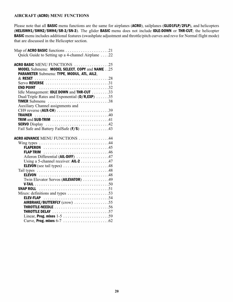
AIRCRAFT (ACRO) MENU FUNCTIONS
Please note that all BASIC menu functions are the same for airplanes (ACRO), sailplanes (GLID1FLP/2FLP), and helicopters(HELISWH1/SWH2/SWH4/SR-3/SN-3). The glider BASIC menu does not include IDLE-DOWN or THR-CUT; the helicopterBASIC menu includes additional features (swashplate adjustment and throttle/pitch curves and revo for Normal flight mode)that are discussed in the Helicopter section.
Map of ACRO BASIC functions . . . . . . . . . . . . . . . . . . . .21Quick Guide to Setting up a 4-channel Airplane . . . .22
ACRO BASIC MENU FUNCTIONS . . . . . . . . . . . . . . . .25MODEL Submenu: MODEL SELECT, COPY and NAME . .25PARAMETER Submenu: TYPE, MODUL, ATL, AIL2,& RESET . . . . . . . . . . . . . . . . . . . . . . . . . . . . . . . . . .28Servo REVERSE . . . . . . . . . . . . . . . . . . . . . . . . . . . . .31END POINT . . . . . . . . . . . . . . . . . . . . . . . . . . . . . . . .32Idle Management: IDLE DOWN and THR-CUT . . . . . . . .33Dual/Triple Rates and Exponential (D/R,EXP) . . . . . .35TIMER Submenu . . . . . . . . . . . . . . . . . . . . . . . . . . . .38Auxiliary Channel assignments and CH9 reverse (AUX-CH) . . . . . . . . . . . . . . . . . . . . . . . .39TRAINER . . . . . . . . . . . . . . . . . . . . . . . . . . . . . . . . . .40TRIM and SUB-TRIM . . . . . . . . . . . . . . . . . . . . . . . . . .41SERVO Display . . . . . . . . . . . . . . . . . . . . . . . . . . . . .42Fail Safe and Battery FailSafe (F/S) . . . . . . . . . . . . .43
ACRO ADVANCE MENU FUNCTIONS . . . . . . . . . . . . . .44Wing types . . . . . . . . . . . . . . . . . . . . . . . . . . . . . . . .44
FLAPERON . . . . . . . . . . . . . . . . . . . . . . . . . . . . . .45FLAP TRIM . . . . . . . . . . . . . . . . . . . . . . . . . . . . . .46Aileron Differential (AIL-DIFF) . . . . . . . . . . . . . . .47Using a 5-channel receiver: AIL-2 . . . . . . . . . . . . .47ELEVON (see tail types) . . . . . . . . . . . . . . . . . . . . .48
Tail types . . . . . . . . . . . . . . . . . . . . . . . . . . . . . . . . .48ELEVON . . . . . . . . . . . . . . . . . . . . . . . . . . . . . . . .48Twin Elevator Servos (AILEVATOR) . . . . . . . . . . . .49V-TAIL . . . . . . . . . . . . . . . . . . . . . . . . . . . . . . . . . .50
SNAP ROLL . . . . . . . . . . . . . . . . . . . . . . . . . . . . . . . .51Mixes: definitions and types . . . . . . . . . . . . . . . . . . .53
ELEV-FLAP . . . . . . . . . . . . . . . . . . . . . . . . . . . . . .54AIRBRAKE/BUTTERFLY (crow) . . . . . . . . . . . . . . . .55THROTTLE-NEEDLE . . . . . . . . . . . . . . . . . . . . . . . . .56THROTTLE DELAY . . . . . . . . . . . . . . . . . . . . . . . . . .57Linear, Prog. mixes 1-5 . . . . . . . . . . . . . . . . . . . . .59Curve, Prog. mixes 6-7 . . . . . . . . . . . . . . . . . . . . .62
20
21
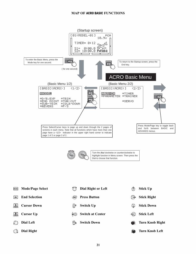
MAP OF ACRO BASIC FUNCTIONS
ACRO Basic Menu
End
Mode/PageTo enter the Basic Menu, press theMode key for one second.
( for one second)
(Startup screen)
(Basic Menu 1/2)
Select(Cursor)
To return to the Startup screen, press theEnd key.
(Basic Menu 2/2)
Turn the Dial clockwise or counterclockwise tohighlight function in Menu screen. Then press the Dial to choose that function.
Press Select/Cursor keys to page up and down through the 2 pages of screens in each menu. Note that all functions which have more than one page have a <1/2> indicator in the upper right hand corner to indicate page 1 of 2 or page 2 of 2.
Press Mode/Page key to toggle back and forth between BASIC and ADVANCE menus.
Mode/Page
Mode/Page Select
End Selection
Cursor Down
Cursor Up
Dial Left
Dial Right
Dial Right or Left
Press Button
Switch Up
Switch at Center
Switch Down
Stick Up
Stick Right
Stick Down
Stick Left
Turn Knob Right
Turn Knob Left
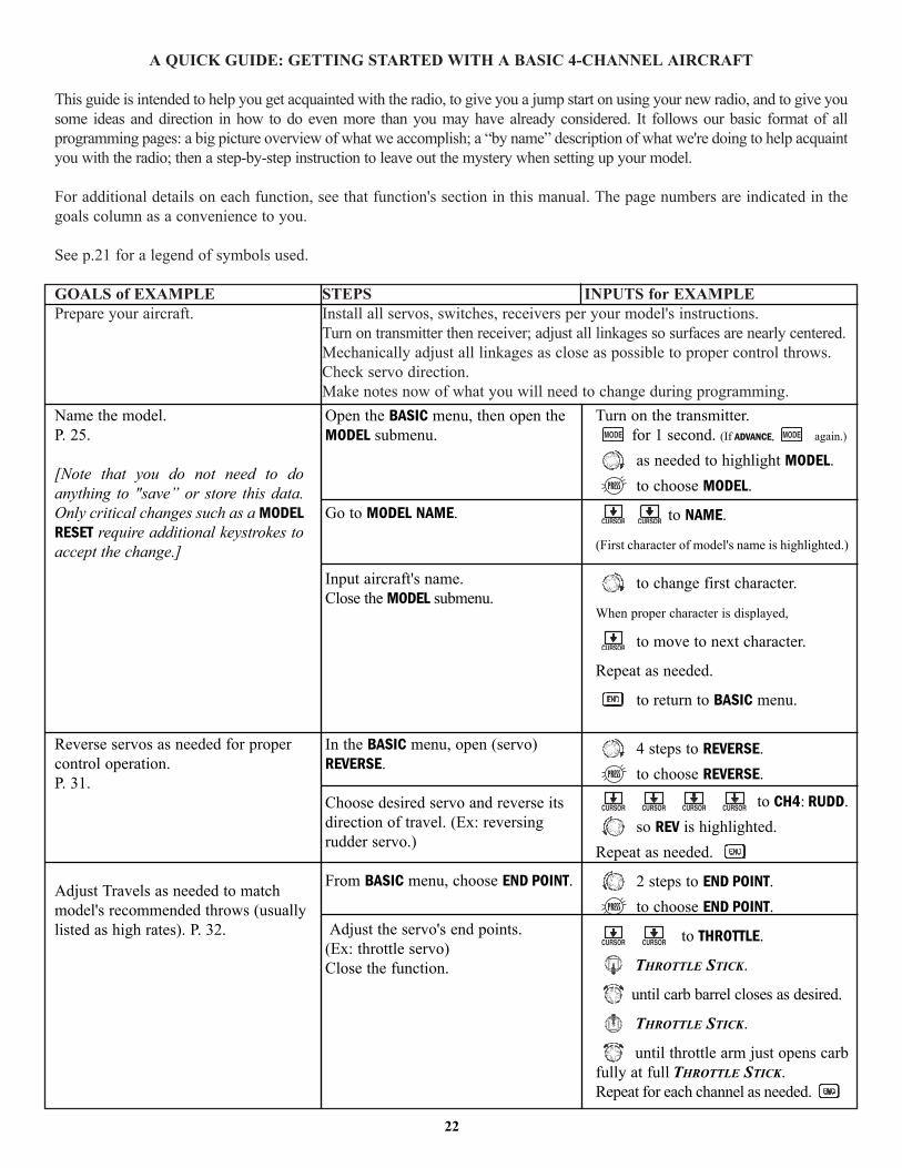
A QUICK GUIDE: GETTING STARTED WITH A BASIC 4-CHANNEL AIRCRAFT
This guide is intended to help you get acquainted with the radio, to give you a jump start on using your new radio, and to give yousome ideas and direction in how to do even more than you may have already considered. It follows our basic format of allprogramming pages: a big picture overview of what we accomplish; a “by name” description of what we're doing to help acquaintyou with the radio; then a step-by-step instruction to leave out the mystery when setting up your model.
For additional details on each function, see that function's section in this manual. The page numbers are indicated in thegoals column as a convenience to you.
See p.21 for a legend of symbols used.
GOALS of EXAMPLE STEPS INPUTS for EXAMPLEPrepare your aircraft. Install all servos, switches, receivers per your model's instructions.
Turn on transmitter then receiver; adjust all linkages so surfaces are nearly centered.Mechanically adjust all linkages as close as possible to proper control throws.Check servo direction.Make notes now of what you will need to change during programming.
22
Name the model.P. 25.
[Note that you do not need to doanything to "save” or store this data.Only critical changes such as a MODELRESET require additional keystrokes toaccept the change.]
Reverse servos as needed for propercontrol operation.P. 31.
Adjust Travels as needed to matchmodel's recommended throws (usuallylisted as high rates). P. 32.
Open the BASIC menu, then open theMODEL submenu.
Go to MODEL NAME.
Input aircraft's name.Close the MODEL submenu.
In the BASIC menu, open (servo)REVERSE.
Choose desired servo and reverse itsdirection of travel. (Ex: reversingrudder servo.)
From BASIC menu, choose END POINT.
Adjust the servo's end points.(Ex: throttle servo)Close the function.
Turn on the transmitter.for 1 second. (If ADVANCE, again.)
as needed to highlight MODEL.to choose MODEL.
to NAME.
(First character of model's name is highlighted.)
to change first character.
When proper character is displayed,
to move to next character.
Repeat as needed.
to return to BASIC menu.
4 steps to REVERSE.to choose REVERSE.
to CH4: RUDD.so REV is highlighted.
Repeat as needed.
2 steps to END POINT.to choose END POINT.
to THROTTLE.
THROTTLE STICK.
until carb barrel closes as desired.
THROTTLE STICK.
until throttle arm just opens carbfully at full THROTTLE STICK.Repeat for each channel as needed.
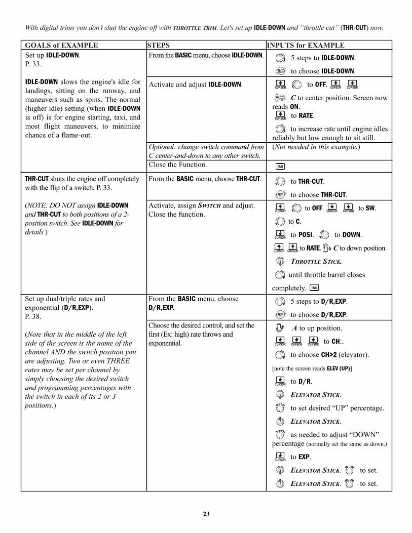
With digital trims you don’t shut the engine off with THROTTLE TRIM. Let's set up IDLE-DOWN and “throttle cut” (THR-CUT) now.
GOALS of EXAMPLE STEPS INPUTS for EXAMPLE
23
Set up IDLE-DOWN.P. 33.
IDLE-DOWN slows the engine's idle forlandings, sitting on the runway, andmaneuvers such as spins. The normal(higher idle) setting (when IDLE-DOWNis off) is for engine starting, taxi, andmost flight maneuvers, to minimizechance of a flame-out.
From the BASIC menu, choose IDLE-DOWN.
Activate and adjust IDLE-DOWN.
Optional: change switch command fromC center-and-down to any other switch.Close the Function.
5 steps to IDLE-DOWN.
to choose IDLE-DOWN.
to OFF.
C to center position. Screen nowreads ON.
to RATE.
to increase rate until engine idlesreliably but low enough to sit still.(Not needed in this example.)
THR-CUT shuts the engine off completelywith the flip of a switch. P. 33.
(NOTE: DO NOT assign IDLE-DOWNand THR-CUT to both positions of a 2-position switch. See IDLE-DOWN fordetails.)
Set up dual/triple rates andexponential (D/R,EXP).P. 38.
(Note that in the middle of the leftside of the screen is the name of thechannel AND the switch position youare adjusting. Two or even THREErates may be set per channel bysimply choosing the desired switchand programming percentages withthe switch in each of its 2 or 3positions.)
From the BASIC menu, choose THR-CUT.
Activate, assign SWITCH and adjust.Close the function.
From the BASIC menu, chooseD/R,EXP.
Choose the desired control, and set thefirst (Ex: high) rate throws andexponential.
to THR-CUT.
to choose THR-CUT.
to OFF. to SW.
to C.
to POSI. to DOWN.
to RATE. C to down position.
THROTTLE STICK.
until throttle barrel closes
completely.
5 steps to D/R,EXP.
to choose D/R,EXP.
A to up position.
to CH:.
to choose CH>2 (elevator).
[note the screen reads ELEV (UP)]
to D/R.
ELEVATOR STICK.
to set desired “UP” percentage.
ELEVATOR STICK.
as needed to adjust “DOWN”percentage (normally set the same as down.)
to EXP.
ELEVATOR STICK. to set.
ELEVATOR STICK. to set.
GOALS of EXAMPLE STEPS INPUTS for EXAMPLE
24
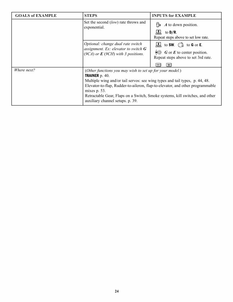
Where next?
Set the second (low) rate throws andexponential.
Optional: change dual rate switchassignment. Ex: elevator to switch G(9CA) or E (9CH) with 3 positions.
A to down position.
to D/R. Repeat steps above to set low rate.
to SW. to G or E.
G or E to center position.Repeat steps above to set 3rd rate.
(Other functions you may wish to set up for your model.)TRAINER p. 40.Multiple wing and/or tail servos: see wing types and tail types, p. 44, 48.Elevator-to-flap, Rudder-to-aileron, flap-to-elevator, and other programmablemixes p. 53.Retractable Gear, Flaps on a Switch, Smoke systems, kill switches, and otherauxiliary channel setups. p. 39.

A LOOK AT THE RADIO'S FUNCTIONS STEP BY STEP
MODEL submenu: includes three functions that manage model memory: MODEL SELECT, MODEL COPY and MODEL NAME.Since these functions are all related, and are all basic features used with most models, they are together in the MODELsubmenu of the BASIC menu.
MODEL SELECT: This function selects which of the 8 model memories in the transmitter(or 6 in the optional CAMPac) to set up or fly. For clarity the model's name and an imageof its type are indicated after its number. (Each model memory may be of a differentmodel type from the other memories.)
Note: If you are using the optional CAMPac, your choices in MODEL SELECT and MODELCOPY will include 9-14, which are the model memories in the CAMPac. You do not have toCOPY from the CAMPac to the transmitter prior to working with that model memory.
GOAL: STEPS: INPUTS:
NOTE: When you choose a new model in theMODEL SELECT function, if the new model is set tothe other modulation, you must cycle the transmitterpower to change modulations. If you do not cyclethe power, the modulation type will flash on thehome screen to remind you. You are stilltransmitting on the other modulation until you affectthis change.
Model type¥ACRO (aircraft)¥GLID (glider)¥HELI (helicopter)
25
Select Model #3.
NOTE: This is one of several functionsfor which the radio requiresconfirmation to make a change.
Open BASIC menu, then open MODELsubmenu.
Choose Model #3.
Confirm your change.
Close.
for 1 second. (If ADVANCE, again.)
if required to MODEL.
to 3.
for 1 second.
sure? displays.
Confirm proper modulation of newmodel memory.Where next?
If PPM or PCM are flashing in the upper right hand corner, then the new model is setfor the other receiver type. Turn the transmitter off/on to change the modulation.NAME the model: see p. 25.Change MODEL TYPE (aircraft, heli, glider): see p. 28.Change modulation [FM (PPM) or PCM]: see p. 28.Utilize servo REVERSE: see p. 31.Adjust END POINTs: see p. 32.Set up IDLE-DOWN and THR-CUT for throttle management: see p. 33.
FLASHING
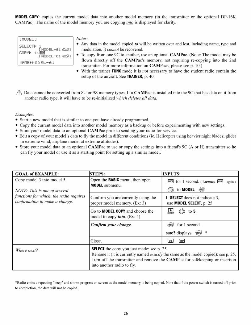
MODEL COPY: copies the current model data into another model memory (in the transmitter or the optional DP-16KCAMPac). The name of the model memory you are copying into is displayed for clarity.
Notes: • Any data in the model copied to will be written over and lost, including name, type and
modulation. It cannot be recovered. • To copy from one 9C to another, use an optional CAMPac. (Note: The model may be
flown directly off the CAMPac's memory, not requiring re-copying into the 2ndtransmitter. For more information on CAMPacs, please see p. 10.)
• With the trainer FUNC mode it is not necessary to have the student radio contain thesetup of the aircraft. See TRAINER, p. 40.
Data cannot be converted from 8U or 9Z memory types. If a CAMPac is installed into the 9C that has data on it fromanother radio type, it will have to be re-initialized which deletes all data.
Examples:• Start a new model that is similar to one you have already programmed.• Copy the current model data into another model memory as a backup or before experimenting with new settings.• Store your model data to an optional CAMPac prior to sending your radio for service.• Edit a copy of your model’s data to fly the model in different conditions (ie. Helicopter using heavier night blades; glider
in extreme wind; airplane model at extreme altitudes).• Store your model data to an optional CAMPac to use or copy the settings into a friend's 9C (A or H) transmitter so he
can fly your model or use it as a starting point for setting up a similar model.
GOAL of EXAMPLE: STEPS: INPUTS:
*Radio emits a repeating "beep" and shows progress on screen as the model memory is being copied. Note that if the power switch is turned off priorto completion, the data will not be copied.
26
Copy model 3 into model 5.
NOTE: This is one of severalfunctions for which the radio requiresconfirmation to make a change.
Where next?
Open the BASIC menu, then openMODEL submenu.
Confirm you are currently using theproper model memory. (Ex: 3)
Go to MODEL COPY and choose themodel to copy into. (Ex: 5)
Confirm your change.
Close.
for 1 second. (If ADVANCE, again.)
to MODEL.
If SELECT does not indicate 3,use MODEL SELECT, p. 25.
to 5.
for 1 second.
sure? displays. *
SELECT the copy you just made: see p. 25.Rename it (it is currently named exactly the same as the model copied): see p. 25.Turn off the transmitter and remove the CAMPac for safekeeping or insertioninto another radio to fly.
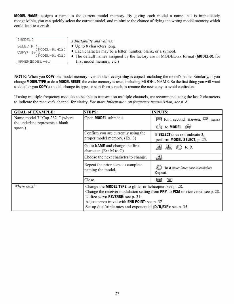
MODEL NAME: assigns a name to the current model memory. By giving each model a name that is immediatelyrecognizable, you can quickly select the correct model, and minimize the chance of flying the wrong model memory whichcould lead to a crash.
Adjustability and values:• Up to 8 characters long.• Each character may be a letter, number, blank, or a symbol.• The default names assigned by the factory are in MODEL-xx format (MODEL-01 for
first model memory, etc.)
NOTE: When you COPY one model memory over another, everything is copied, including the model's name. Similarly, if youchange MODEL TYPE or do a MODEL RESET, the entire memory is reset, including MODEL NAME. So the first thing you will wantto do after you COPY a model, change its type, or start from scratch, is rename the new copy to avoid confusion.
If using multiple frequency modules to be able to transmit on multiple channels, we recommend using the last 2 charactersto indicate the receiver's channel for clarity. For more information on frequency transmission, see p. 8.
GOAL of EXAMPLE: STEPS: INPUTS:
27
Name model 3 “Cap-232_” (wherethe underline represents a blankspace.)
Where next?
Open MODEL submenu.
Confirm you are currently using theproper model memory. (Ex: 3)
Go to NAME and change the firstcharacter. (Ex: M to C)Choose the next character to change.
Repeat the prior steps to completenaming the model.
Close.
for 1 second. (If ADVANCE, again.)
to MODEL.
If SELECT does not indicate 3,perform MODEL SELECT, p. 25.
to C.
to a (note: lower case is available)Repeat.
Change the MODEL TYPE to glider or helicopter: see p. 28.Change the receiver modulation setting from PPM to PCM or vice versa: see p. 28.Utilize servo REVERSE: see p. 31.Adjust servo travel with END POINT: see p. 32.Set up dual/triple rates and exponential (D/R,EXP): see p. 35.
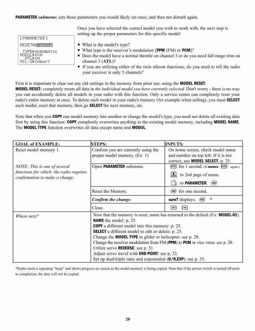
PARAMETER submenu: sets those parameters you would likely set once, and then not disturb again.
Once you have selected the correct model you wish to work with, the next step issetting up the proper parameters for this specific model:
• What is the model's type?• What type is the receiver’s modulation [PPM (FM) or PCM]?• Does the model have a normal throttle on channel 3 or do you need full range trim on
channel 3 (ATL)?• If you are utilizing either of the twin aileron functions, do you need to tell the radio
your receiver is only 5 channels?
First it is important to clear out any old settings in the memory from prior use, using the MODEL RESET.MODEL RESET: completely resets all data in the individual model you have currently selected. Don't worry - there is no wayyou can accidentally delete all models in your radio with this function. Only a service center can completely reset yourradio's entire memory at once. To delete each model in your radio's memory (for example when selling), you must SELECTeach model, reset that memory, then go SELECT the next memory, etc.
Note that when you COPY one model memory into another or change the model's type, you need not delete all existing datafirst by using this function. COPY completely overwrites anything in the existing model memory, including MODEL NAME.The MODEL TYPE function overwrites all data except name and MODUL.
GOAL of EXAMPLE: STEPS: INPUTS:
*Radio emits a repeating “beep” and shows progress on screen as the model memory is being copied. Note that if the power switch is turned off priorto completion, the data will not be copied.
28
Reset model memory 1.
NOTE: This is one of severalfunctions for which the radio requiresconfirmation to make a change.
Where next?
Confirm you are currently using theproper model memory. (Ex: 1)
Open PARAMETER submenu.
Reset the Memory.
Confirm the change.
Close.
On home screen, check model nameand number on top left. If it is notcorrect, use MODEL SELECT, p. 25.
for 1 second. (If ADVANCE, again.)
to 2nd page of menu.
to PARAMETER.
for one second.
sure? displays. *
Now that the memory is reset, name has returned to the default (Ex: MODEL-01).NAME the model: p. 25.COPY a different model into this memory: p. 25.SELECT a different model to edit or delete: p. 25.Change the MODEL TYPE to glider or helicopter: see p. 28.Change the receiver modulation from FM (PPM) to PCM or vice versa: see p. 28.Utilize servo REVERSE: see p. 31.Adjust servo travel with END POINT: see p. 32.Set up dual/triple rates and exponential (D/R,EXP): see p. 35.
MODEL TYPE: sets the type of programming used for this model.The 9C has 8 model memories, which can each support:• one powered aircraft (ACRO) memory type (with multiple wing and tail configurations. See twin aileron servos, twin
elevator servos, ELEVON, and V-TAIL for further information.);• two glider wing types (again with multiple tail configurations). See Glider MODEL TYPE for details, p. 68;• five helicopter swashplate types, including CCPM. See Helicopter MODEL TYPE for details, p. 77.
Before doing anything else to set up your aircraft, first you must decide which MODEL TYPE best fits this particular aircraft.(Each model memory may be set to a different model type.) If your transmitter is a 9CA, the default is ACRO. If it is a 9CH,the default is HELI(SW1).
ACRO is the best choice for most powered airplanes, but in some circumstances, GLID2FLP may be a better choice. ACROis usually a better choice because of functions it offers that the GLID types do not:
• ACRO adds:• SNAP-ROLL• AILEVATOR (twin elevator servo support)• AIRBRAKE (a more assignable version of BUTTERFLY)• For fuel-powered airplanes: IDLE-DOWN, THR-CUT, THROTTLE-NEEDLE mixing and THROTTLE DELAY programming.
• But ACRO lacks:• START and SPEED OFFSETS• Built-in programming which defaults outboard ailerons as flaperons and sets up two flap servos to
also operate as flaperons for a 4-trailing-edge-surface wing.
If you are using a glider or heli MODEL TYPE, please go to that chapter now to select the proper model type and supportyour model setup. Note that changing MODEL TYPE resets all data for the model memory, including its name.
GOAL of EXAMPLE: STEPS: INPUTS:
29
Select the proper MODEL TYPE for yourmodel. Ex: ACRO.
[NOTE: This is one of several functionsthat requires confirmation to make achange. Only critical changes (see p xxxxfor listing) require additional keystrokesto accept the change.]
Open the BASIC menu, then open thePARAMETER submenu.
Go to MODEL TYPE.
Select proper MODEL TYPE.Ex: ACRO.
Confirm the change. Close PARAMETER.
Turn on the transmitter.for 1 second. (If ADVANCE, again.)
then to highlight PARAMETER.to choose PARAMETER.
to TYPE.
to ACROBATIC. for 1 second.
sure? displays. to confirm.
to return to BASIC menu.

Modulation select (MODUL): sets the type of modulation transmitted.The modulation of your receiver will determine whether you utilize PPM or PCM setting in MODUL during transmission.Note that you have to turn your transmitter off and back on before a modulation change becomes effective. If you choosePCM, be sure you understand and set the FailSafe (F/S) settings as you intended (see p. 43). Both modulations transmit onFM waves, use the FM trainer cord, and the FM module.
PCM = Pulse Code Modulation PPM = Pulse Position Modulation (also called FM).
Adjustability:• PCM setting for all Futaba PCM1024 receivers, regardless of number of channels (ie.
R138DP/148DP/149DP, R309DPS);• PPM setting for all Futaba compatible (negative shift) FM receivers, regardless of
number of channels (ie. R127DF, R123F, R148DF).• Not compatible with PCM512 receivers such as the R128DP and R105iP.• Not compatible with other brands of PCM receiver, or positive shift FM receivers
(ie. JR, Airtronics).• You do not need a different module in the radio to transmit in PCM. For more
information on PCM, please see our website.
GOAL of EXAMPLE: STEPS: INPUTS:
Second aileron (AIL-2) (ACRO/ GLID1FLP only): changes the default choice for dual aileron servos from channels 6(FLAPERON) or 7 (AIL-DIF) to channels 5 and 6. This allows you to utilize these 2 great functions while utilizing a 5-channelreceiver. NOTE: Changing AIL-2 only tells the system which servos to utilize if FLAPERON or AIL-DIF is activated. You stillmust activate that function and complete its setup. For details on twin aileron servos, including using AIL-2, see p. 47.
NOTE: When you change models in MODEL SELECT, if thenew model is set to the other modulation type, you mustcycle the transmitter power to change modulations. Themodulation will flash on the home screen to remind youuntil you do so. See p. 25, MODEL SELECT, for details.
30
Change model 1 from FM (PPM) toPCM.
Where next?
Confirm you are currently using theproper model memory (Ex: 1)
Open BASIC menu, then openPARAMETER submenu.
Go to MODUL and change setting.
Close menu and cycle power.
On home screen, check model name andnumber on top left and the modulationon top right. If it is not the correctmodel, use MODEL SELECT, p. 25.
for 1 second. (If ADVANCE, again.)
to 2nd page of menu.
to PARAMETER.
to MODUL. to PCM.cycle power flashes on screen
POWER OFF. POWER ON.Now that the model is in the proper modulation, the 9C should communicatewith the receiver. If it does not, confirm the modulation/frequency of thereceiver. [Futaba receivers ending in F use PPM (ex: R127DF), ending in P usePCM (ex: R149DP)].Change MODEL TYPE to glider/helicopter: see p. 28.Set F/S settings for when PCM receiver sees interference: see p. 43.Utilize servo REVERSE: see p. 31.Adjust servo travel with END POINT: see p. 32.Set up dual/triple rates and exponential (D/R,EXP): see p. 35.

Adjustable travel limit (ATL): makes the channel 3 TRIM LEVER (THROTTLE TRIM) effective only at low throttle, disabling the trimat high throttle. This prevents pushrod jamming due to idling trim changes. This function defaults to ON. If you are not usingchannel 3 for throttle, you may want trim operation the same as on all other channels. To do so, set ATL to OFF.
If you need the ATL to be effective at the top of the stick instead of the bottom, reverse the THR-REV setting. Note that thisaffects all models in the radio, not just the model you are currently editing. See servo REVERSE, p. 31.
GOAL of EXAMPLE: STEPS: INPUTS:
Servo reversing (REVERSE): changes the direction an individual servo responds to a CONTROL STICK motion. [Since channel 9 isswitch only (and only available with a PCM receiver), its servo REVERSE is in the AUX-CH control screen with its switch assignment.See p. 39.] For CCPM helicopters, be sure to read the section on SWASH AFR (p. 79) before reversing any servos.
Except with CCPM helicopters, always complete your servo reversing prior to anyother programming. If you use pre-built ACRO/GLID functions that control multipleservos, such as FLAPERON or V-TAIL, it may be confusing to tell whether the servo needsto be reversed or a setting in the function needs to be reversed. See the instructions foreach specialized function for further details.
Always check servo direction prior to every flight as an additional precaution to confirm proper model memory,hook ups, and radio function.
NOTE: THR-REV is a special function that reverses the entire throttle control, including moving the trim functionality to theStick’s upper half. To use THR-REV, turn off the transmitter, hold down the MODE and END keys, turn on. CURSOR DOWN toTHR-REV and turn the DIAL to REV. Turn the transmitter off and back on. This change affects all models in the radio.
GOAL of EXAMPLE: STEPS: INPUTS:
31
Change ATL from ON to OFF forbattling robot, tank, airbrake andother channel 3 uses.
Where next?
Open BASIC menu, then openPARAMETER submenu.
Go to ATL and Change. (Ex: to OFF)
Close.
for 1 second. (If ADVANCE, again.)
to 2nd page of menu.
to PARAMETER.
to OFF.
Set up ELEVON for tank-style control, throttle/steering on one STICK: see p. 48.Set up IDLE-DOWN and THR-CUT to adjust channel 3 servo at low-stick: see p. 33.Reassign auxiliary channels 5-9 (ex: from dial to switch/slider): see p. 39.Utilize servo REVERSE: see p. 31.Adjust servo travel with END POINT: see p. 32.Set up dual/triple rates and exponential (D/R,EXP): see p. 35.
Reverse the direction of the elevatorservo.
Where next?
Open REVERSE function.
Choose proper channel and setdirection. (Ex: ELE REV)
Close.
for 1 second. (If ADVANCE, again.)
to REVERSE.
to ELE.
to REV.
Adjust servo travel with END POINT: see p. 32.Set up dual/triple rates and exponential (D/R,EXP): see p. 35.Set up flight timers: see p. 38.Set up trainer functions: see p. 40.

End Point of servo travel adjustment (END POINT, also called EPA): the most flexible version of travel adjustmentavailable. It independently adjusts each end of each individual servo’s travel, rather than one setting for the servo thataffects both directions. Again, for CCPM helicopters, be sure to see SWASH AFR (see p. 79) prior to adjusting end points.
Adjustability:
• Can set each direction independently.• Ranges from 0% (no servo movement at all) to 140%. At a 100% setting, the throw of
the servo is approximately 40° for channels 1-4 and approximately 55° for channels 5-8. • Reducing the percentage settings reduces the total servo throw in that direction.
Examples:• Adjust the throttle high end to avoid binding at the carburetor, and low end to allow for proper carburetor closure. • Adjust flap so up travel is only sufficient for straight and level flight trimming, with full down travel.• END POINT may be adjusted to 0 to keep a servo from moving one direction, such as flaps not intended to also operate
as spoilers.• Retract servos are not proportional. Changing END POINT will not adjust the servo.
END POINT adjusts only the individual servo. It will have no effect on any other servo that is operated in conjunction withthis servo via mix or preset programming such as FLAPERON, AILEVATOR, etc. This is so that each individual servo can becarefully fine-tuned to avoid binding and other conflicts. To adjust the total travel of a function such as FLAPERON, makethe adjustments in that function's controls. For CCPM helicopters, adjust the total travel of the function, such as collectivepitch, in SWASH AFR.
Adjust the linkage or the END POINT? It is nearly always best to adjust your linkages to get as close as possible prior toutilizing END POINT. The higher the END POINT setting, the better position accuracy and the more servo power available atnearly any position (except if using digital servos). Higher END POINT values also mean longer travel time to reach thedesired position, as you are utilizing more of the servo's total travel. (For example, using 50% END POINT would give youonly half the steps of servo travel, meaning every click of trim has twice the effect and the servo gets there in half the time).• end point (and moving the linkage) = torque, accuracy, but transit time to get there. • end point (instead of adjusting linkages) = travel time, but torque, accuracy.
GOAL of EXAMPLE: STEPS: INPUTS:
*You can reset to the initial values by pressing the DIAL for one second.
32
Decrease the flap servo throw in theupward direction to 5% to allowtrimming of level flight only and downtravel to 85% to prevent binding.
Where next?
Open END POINT function.
Choose proper channel and setdirection. (Ex: flap up 5%)
Close.
for 1 second. (If ADVANCE, again.)
to END POINT.
to flap.
flap control [default is VR(A)].
to 5%.*
VR(A). to 85%.
Go to SERVO display to confirm desired end result: see p. 42.Move auxiliary channels 5-9 to different dial(s)/switch(es)/slider(s): see p. 39.Set up IDLE-DOWN and THR-CUT to slow/cut the engine: see p. 33.Set up dual/triple rates and exponential (D/R,EXP): see p. 35.Set up flight timers: see p. 38.Set up trainer functions: see p. 40.Set up twin aileron servos: see p. 44.Set up twin elevator servos: see p. 49.

Engine idle management: IDLE-DOWN and THR-CUT: functions which work with the digital THROTTLE TRIM to provide asimple, consistent means of engine operation. No more fussing with getting trim in just the right spot for landings or takeoffs! For additional engine adjustments, see THROTTLE-NEEDLE (p. 56) and THROTTLE DELAY (p. 57).
If your throttle cut and idle down are working at the wrong end of your travel — full throttle not idle — then yourTHR REV feature has been reversed. Please see page 31 for instructions.
IDLE-DOWN (ACRO only): lowers the engine idle for: sitting on the runway prior to take off, stalls and spins, and landings.The normal idle setting is a little higher for easier starts and safe flights with less risk of dead sticks.
Important note: The IDLE-DOWN function is not normally used when starting theengine, and its accidental operation may keep your engine from starting. The 9Cwarns that IDLE-DOWN is on when the transmitter is turned on. Be sure to turn off thefunction, or override the warning by pressing both 2 SELECT/CURSOR keys in unisonand holding for 1 second if you intended the function to be on.
This may be assigned to any switch/position. Some modelers accidentally assign IDLE-DOWN to one side of a switchand THR-CUT to the other. There is no “normal” setting to start the engine. By default IDLE-DOWN is set to SWITCHC center and down. This works well with THR-CUT also on SWITCH C down. The SWITCH up is normal flight/starting,center for slower maneuvers/landing, and down to cut the engine. If you assign IDLE-DOWN or THR-CUT to the spring-loaded TRAINER SWITCH F (9CA) or H (9CH), then use the trainer function, you may risk loss of throttle control ordeadstick for your student.
GOAL of EXAMPLE: STEPS: INPUTS:
*Normally a value of 10- 20%. Secure the fuselage, engine running. Set the THROTTLE STICK to idle. Adjust the IDLE-DOWN rate while flipping theswitch ON and OFF until the desired idle is achieved. Be sure to throttle up periodically to allow the engine to “clean out” and idle reliably.
33
Decrease the throttle setting at idlewith the flip of a switch for spins andlandings.
Where next?
Open BASIC menu, then open IDLE-DOWN function.
Activate the function.With THROTTLE STICK at idle, adjustthe rate until engine idles as desired.*
Optional: change switch assignment.Choose desired switch and position.
Close.
for 1 second. (If ADVANCE, again.)
to IDLE-DOWN.
THROTTLE STICK.
until engine idles as desired.
to SW. to desired SWITCH.
to POSI. to desired position.
THR-CUT: see p. 34.
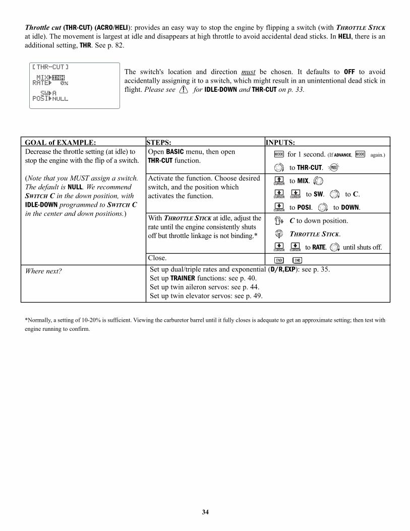
Throttle cut (THR-CUT) (ACRO/HELI): provides an easy way to stop the engine by flipping a switch (with THROTTLE STICKat idle). The movement is largest at idle and disappears at high throttle to avoid accidental dead sticks. In HELI, there is anadditional setting, THR. See p. 82.
The switch's location and direction must be chosen. It defaults to OFF to avoidaccidentally assigning it to a switch, which might result in an unintentional dead stick inflight. Please see for IDLE-DOWN and THR-CUT on p. 33.
GOAL of EXAMPLE: STEPS: INPUTS:
*Normally, a setting of 10-20% is sufficient. Viewing the carburetor barrel until it fully closes is adequate to get an approximate setting; then test withengine running to confirm.
34
Decrease the throttle setting (at idle) tostop the engine with the flip of a switch.
(Note that you MUST assign a switch.The default is NULL. We recommendSWITCH C in the down position, withIDLE-DOWN programmed to SWITCH Cin the center and down positions.)
Where next?
Open BASIC menu, then open THR-CUT function.
Activate the function. Choose desiredswitch, and the position whichactivates the function.
With THROTTLE STICK at idle, adjust therate until the engine consistently shutsoff but throttle linkage is not binding.*
Close.
for 1 second. (If ADVANCE, again.)
to THR-CUT.
to MIX.
to SW. to C.
to POSI. to DOWN.
C to down position.
THROTTLE STICK.
to RATE. until shuts off.
Set up dual/triple rates and exponential (D/R,EXP): see p. 35.Set up TRAINER functions: see p. 40.Set up twin aileron servos: see p. 44.Set up twin elevator servos: see p. 49.

Dual/triple rates and exponential (D/R,EXP): assigns adjusted rates and exponential.
Dual/Triple Rates: reduce/increase the servo travel by flipping a switch, or(ACRO/GLIDER) they can be engaged by any stick position. Dual rates affect the controllisted, such as aileron, not just a single (ex: channel 1) servo. For example, adjustingaileron dual rate will affect both aileron servos when using FLAPERON or AIL-DIF, and bothaileron and elevator servos’ travel when using AILEVATOR or ELEVON or a CCPM helicopter.
Activation:
• Any SWITCH, A-H. If you choose a 3-position switch, then that dual rate instantly becomes a triple rate (see example).
• Stick position (ACRO/GLIDER). (Ex: On rudder you normally use only the center 3/4 of the stick movement exceptfor extreme maneuvers such as snaps/spins/stalls. As long as your RUDDER STICK does not exceed 90% of maximumthrow, the rudder responds at your lower rate, allowing small, gentle corrections. When the stick passes 90% (ie. stallturn), the rudder goes to high rate’s 90%, which is a MUCH higher amount of travel than your low rate at 89%.)
Ex: EPA = 1” Low Rate = 50% High Rate = 100%At 89% Low Rate = .45”At 90% High Rate = .9”
Adjustability:
• Range: 0 - 140% (0 setting would deactivate the control completely.)Initial value=100%
• Adjustable for each direction(ACRO/GLIDER). (ie. Up/down,left/right) (Ex: Most models fly upright without any elevator trim,but require some down elevator when inverted just to maintainlevel flight. By increasing the down travel by the amount requiredto hold the model inverted, the model now has equal travelavailable from level upright or level inverted.)
Exponential: changes the response curve of the servos relative to the stick position to make flying more pleasant. You can make the servo movement less or more sensitive around neutral for rudder, aileron, elevator, and throttle (except HELItype - use THROTTLE CURVE instead).
Why use expo? Many models require a large amount of travel to perform their best tricks. However, without exponential,they are “touchy” around neutral, making them unpleasant to fly and making small corrections very difficult. Additionally,by setting different exponentials for each rate, you can make the effectiveness of small corrections similar in each rate, asin our example below.
The best way to understand exponential is to try it: • Having made no changes yet in the D/R,EXP screen, move SWITCH D to “down” (toward the AILERON STICK). • Cursor down to EXP and dial to 100%. • Move SWITCH D up. Hold the AILERON STICK at ¼ stick and move SWITCH D down. • Notice how much less travel there is.• Go to 3/4 stick and repeat. Notice how the travel is much closer, if not identical.
High Rate
High Rate
High RateLow Rate
Low Rate
100% 100%
100%30%0%
90% 90%0%
35

Adjustability:
• More sensitive around neutral. (positive exponential, see example)• Less sensitive around neutral. (negative exponential, see example)• Adjustable for each direction. (ACRO/GLIDER)
For throttle, exponential is applied at the low end to help nitro and gasoline engines have a linear throttle response, so thateach 1/4 stick increases engine RPM 25% of the available range. (In most engines this ranges from 5-60%.)
Special note for helicopters: Helicopter model types have just a single rate for each switch position rather than a rate foreach side of the servo’s travel per switch position. Additionally, setting the D/R,EXP for each switch position requirescursoring back to the No. setting and changing the switch position here. Just flipping the switch does not affect the screensetting, allowing dual rates to be assigned with idle-up and other features on certain switches, and does not require puttingthe model in that condition to make modifications.
GOAL of EXAMPLE: STEPS: INPUTS:
36
Set up dual rates and exponential in aHELI model.
Open D/R,EXP.
Choose channel.
Choose first switch position.
Set rate and exponential (Ex: high rate= 95%, 0% exponential.)
Go to 2nd switch position and set rateand exponential.
Optional: if using a 3 position switch,set 3rd rate.
Optional: assign dual rates to haveone for each condition.
for 1 second. (If ADVANCE, again.)
to D/R,EXP.
to desired channel.
to UUPP.
to 95%.
Confirm 0% EXP.
to DN. Repeat above.
to CT. Repeat above.
to COND.Repeat steps above to adjust for eachcondition.
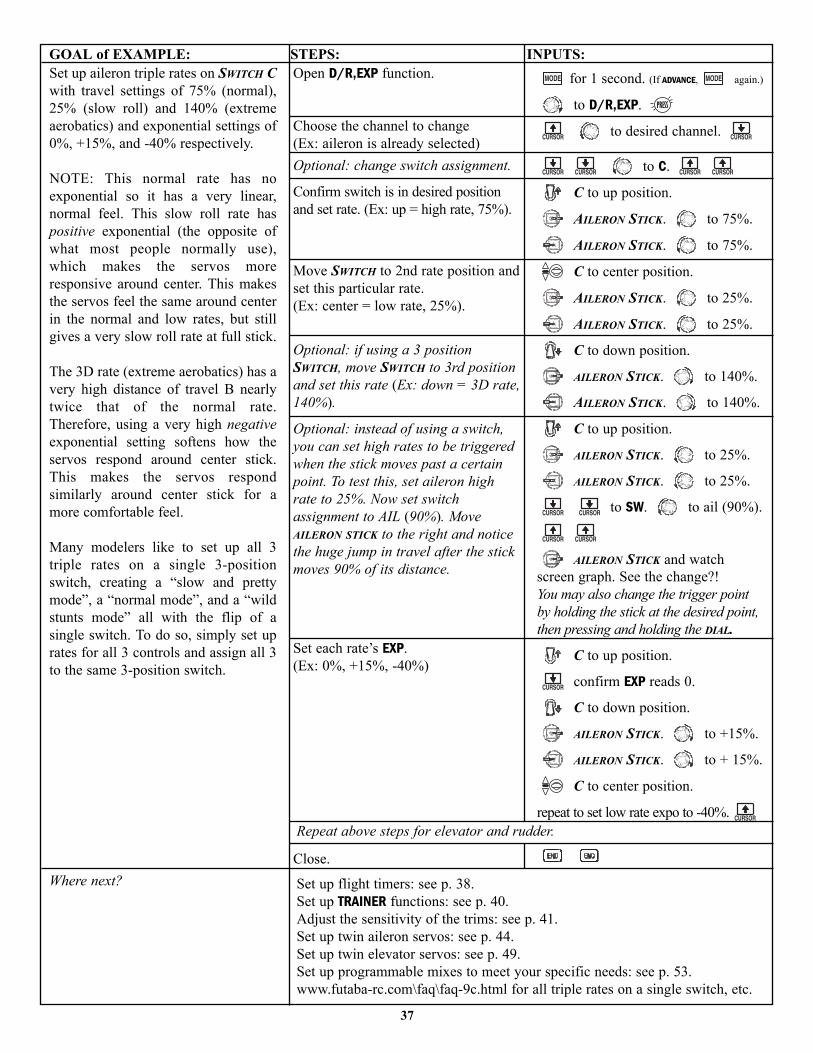
GOAL of EXAMPLE: STEPS: INPUTS:
37
Set up aileron triple rates on SWITCH Cwith travel settings of 75% (normal),25% (slow roll) and 140% (extremeaerobatics) and exponential settings of0%, +15%, and -40% respectively.
NOTE: This normal rate has noexponential so it has a very linear,normal feel. This slow roll rate haspositive exponential (the opposite ofwhat most people normally use),which makes the servos moreresponsive around center. This makesthe servos feel the same around centerin the normal and low rates, but stillgives a very slow roll rate at full stick.
The 3D rate (extreme aerobatics) has avery high distance of travel B nearlytwice that of the normal rate.Therefore, using a very high negativeexponential setting softens how theservos respond around center stick.This makes the servos respondsimilarly around center stick for amore comfortable feel.
Many modelers like to set up all 3triple rates on a single 3-positionswitch, creating a “slow and prettymode”, a “normal mode”, and a “wildstunts mode” all with the flip of asingle switch. To do so, simply set uprates for all 3 controls and assign all 3to the same 3-position switch.
Where next?
Open D/R,EXP function.
Choose the channel to change (Ex: aileron is already selected)Optional: change switch assignment.
Confirm switch is in desired positionand set rate. (Ex: up = high rate, 75%).
Move SWITCH to 2nd rate position andset this particular rate. (Ex: center = low rate, 25%).
Optional: if using a 3 positionSWITCH, move SWITCH to 3rd positionand set this rate (Ex: down = 3D rate,140%).
Optional: instead of using a switch,you can set high rates to be triggeredwhen the stick moves past a certainpoint. To test this, set aileron highrate to 25%. Now set switchassignment to AIL (90%). MoveAILERON STICK to the right and noticethe huge jump in travel after the stickmoves 90% of its distance.
Set each rate’s EXP.(Ex: 0%, +15%, -40%)
Close.
for 1 second. (If ADVANCE, again.)
to D/R,EXP.
to desired channel.
to C.
C to up position.
AILERON STICK. to 75%.
AILERON STICK. to 75%.
C to center position.
AILERON STICK. to 25%.
AILERON STICK. to 25%.
C to down position.
AILERON STICK. to 140%.
AILERON STICK. to 140%.
C to up position.
AILERON STICK. to 25%.
AILERON STICK. to 25%.
to SW. to ail (90%).
AILERON STICK and watchscreen graph. See the change?!You may also change the trigger pointby holding the stick at the desired point,then pressing and holding the DIAL.
C to up position.
confirm EXP reads 0.
C to down position.
AILERON STICK. to +15%.
AILERON STICK. to + 15%.
C to center position.
repeat to set low rate expo to -40%.
Set up flight timers: see p. 38.Set up TRAINER functions: see p. 40.Adjust the sensitivity of the trims: see p. 41.Set up twin aileron servos: see p. 44.Set up twin elevator servos: see p. 49.Set up programmable mixes to meet your specific needs: see p. 53.www.futaba-rc.com\faq\faq-9c.html for all triple rates on a single switch, etc.
Repeat above steps for elevator and rudder.

TIMER submenu (stopwatch functions): controls two electronic clocks used to keep track of time remaining in a competition timeallowed, flying time on a tank of fuel, amount of time on a battery, etc.
Adjustability:• Count down timer: starts from the chosen time, displays time remaining. If the time is exceeded, it continues to count
below 0.• Count up timer: starts at 0 and displays the elapsed time up to 99 minutes 59 seconds.• Independent to each model, and automatically updates with model change.• In either TIMER mode, the timer beeps once each minute. During the last twenty seconds, there's a beep each two seconds.
During the last ten seconds, there's a beep each second. A long tone is emitted when the time selected is reached.• To Reset, choose the desired timer with the SELECT key (while at the startup screen), then press and hold DIAL for 1 second.• Activation by either direction of SWITCH A-H, by THROTTLE STICK (STK-THR) (Using the THROTTLE STICK is convenient if you
are keeping track of fuel remaining, or for an electric, how much battery is left); or by the power SWITCH (PWRSW).
GOAL of EXAMPLE: STEPS: INPUTS:
38
Set timer 2 to count down 4-1/2minutes, being controlled byTHROTTLE STICK position. This isutilized to keep track of actualThrottle on time to better correlatewith fuel/battery usage.
Where next?
Open BASIC menu, then open TIMER function.
Go to TIMER<2>.
Adjust time to 4 min. 30 sec., count down.
Assign to THROTTLE STICK and settrigger point (if timer is to triggerBELOW this throttle point, soarrow points down).
Close.
for 1 second. (If ADVANCE, again.)
to page 2.
to TIMER.
to 4. to 30.
to SW. 2 steps to STK THR.
to POSI.
THROTTLE STICK to desiredposition (Ex: 1/4 stick).
for 1 second to set.
Adjust END POINTs after first flight test: see p. 32.Adjust auxiliary channel assignments (ex: move flaps to a switch): see p. 39.Set up TRAINER functions: see p. 40.
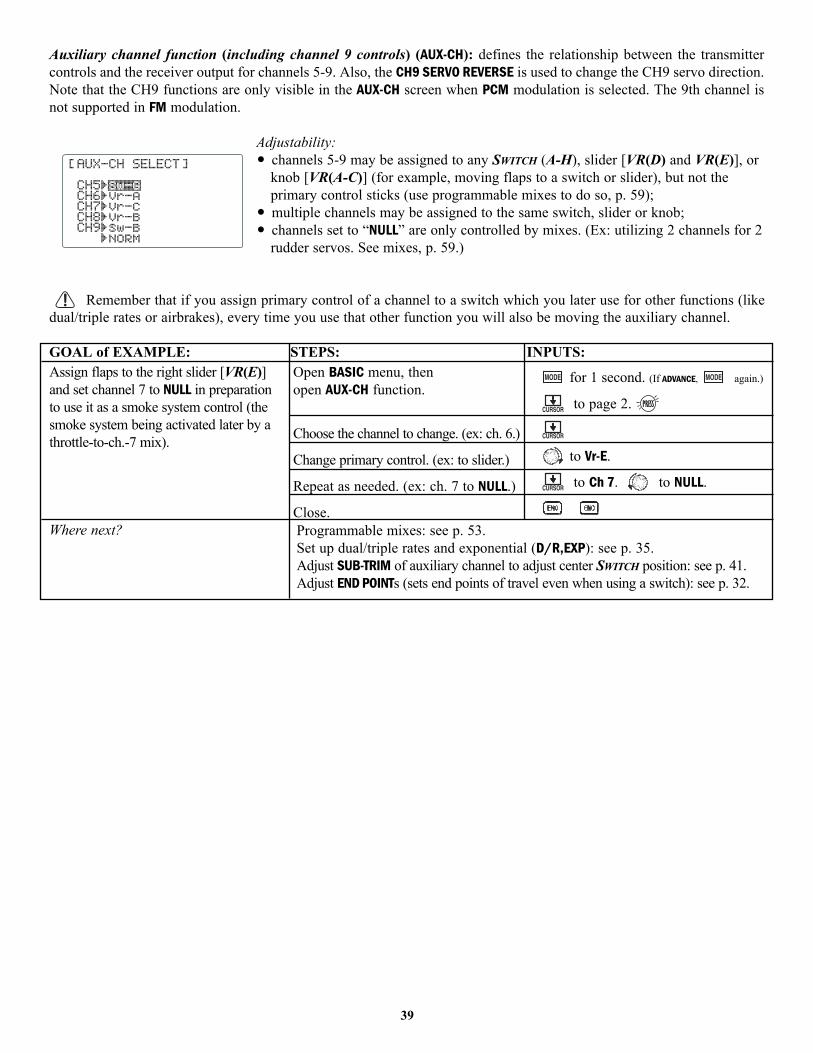
Auxiliary channel function (including channel 9 controls) (AUX-CH): defines the relationship between the transmittercontrols and the receiver output for channels 5-9. Also, the CH9 SERVO REVERSE is used to change the CH9 servo direction.Note that the CH9 functions are only visible in the AUX-CH screen when PCM modulation is selected. The 9th channel isnot supported in FM modulation.
Adjustability:• channels 5-9 may be assigned to any SWITCH (A-H), slider [VR(D) and VR(E)], or
knob [VR(A-C)] (for example, moving flaps to a switch or slider), but not theprimary control sticks (use programmable mixes to do so, p. 59);
• multiple channels may be assigned to the same switch, slider or knob;• channels set to “NULL” are only controlled by mixes. (Ex: utilizing 2 channels for 2
rudder servos. See mixes, p. 59.)
Remember that if you assign primary control of a channel to a switch which you later use for other functions (likedual/triple rates or airbrakes), every time you use that other function you will also be moving the auxiliary channel.
GOAL of EXAMPLE: STEPS: INPUTS:
39
Assign flaps to the right slider [VR(E)]and set channel 7 to NULL in preparationto use it as a smoke system control (thesmoke system being activated later by athrottle-to-ch.-7 mix).
Where next?
Open BASIC menu, then open AUX-CH function.
Choose the channel to change. (ex: ch. 6.)
Change primary control. (ex: to slider.)
Repeat as needed. (ex: ch. 7 to NULL.)
Close.
for 1 second. (If ADVANCE, again.)
to page 2.
to Vr-E.
to Ch 7. to NULL.
Programmable mixes: see p. 53.Set up dual/triple rates and exponential (D/R,EXP): see p. 35.Adjust SUB-TRIM of auxiliary channel to adjust center SWITCH position: see p. 41.Adjust END POINTs (sets end points of travel even when using a switch): see p. 32.
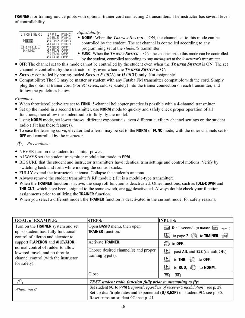
TRAINER: for training novice pilots with optional trainer cord connecting 2 transmitters. The instructor has several levelsof controllability.
Adjustability:• NORM: When the TRAINER SWITCH is ON, the channel set to this mode can be
controlled by the student. The set channel is controlled according to anyprogramming set at the student's transmitter.
• FUNC: When the TRAINER SWITCH is ON, the channel set to this mode can be controlledby the student, controlled according to any mixing set at the instructor's transmitter.
• OFF: The channel set to this mode cannot be controlled by the student even when the TRAINER SWITCH is ON. The setchannel is controlled by the instructor only, even when the TRAINER SWITCH is ON.
• SWITCH: controlled by spring-loaded SWITCH F (9CA) or H (9CH) only. Not assignable.• Compatibility: The 9C may be master or student with any Futaba FM transmitter compatible with the cord. Simply
plug the optional trainer cord (For 9C series, sold separately) into the trainer connection on each transmitter, andfollow the guidelines below.
Examples:• When throttle/collective are set to FUNC, 5-channel helicopter practice is possible with a 4-channel transmitter.• Set up the model in a second transmitter, use NORM mode to quickly and safely check proper operation of all
functions, then allow the student radio to fully fly the model.• Using NORM mode, set lower throws, different exponentials, even different auxiliary channel settings on the student
radio (if it has these features).• To ease the learning curve, elevator and aileron may be set to the NORM or FUNC mode, with the other channels set to
OFF and controlled by the instructor.
Precautions:
• NEVER turn on the student transmitter power.• ALWAYS set the student transmitter modulation mode to PPM.• BE SURE that the student and instructor transmitters have identical trim settings and control motions. Verify by
switching back and forth while moving the control sticks.• FULLY extend the instructor's antenna. Collapse the student's antenna.• Always remove the student transmitter's RF module (if it is a module-type transmitter).• When the TRAINER function is active, the snap roll function is deactivated. Other functions, such as IDLE-DOWN and
THR-CUT, which have been assigned to the same switch, are not deactivated. Always double check your functionassignments prior to utilizing the TRAINER function.
• When you select a different model, the TRAINER function is deactivated in the current model for safety reasons.
GOAL of EXAMPLE: STEPS: INPUTS:
40
Turn on the TRAINER system and setup so student has: fully functionalcontrol of aileron and elevator tosupport FLAPERON and AILEVATOR;normal control of rudder to allowlowered travel; and no throttlechannel control (with the instructorfor safety).
Where next?
Open BASIC menu, then open TRAINER function.
Activate TRAINER.
Choose desired channel(s) and propertraining type(s).
Close.
for 1 second. (If ADVANCE, again.)
to page 2. to TRAINER.
to OFF.
past AIL and ELE (default OK).
to THR, to OFF.
to RUD, to NORM.
TEST student radio function fully prior to attempting to fly!Set student 9C to PPM (required regardless of receiver’s modulation): see p. 28.Set up dual/triple rates and exponential (D/R,EXP) on student 9C: see p. 35.Reset trims on student 9C: see p. 41.
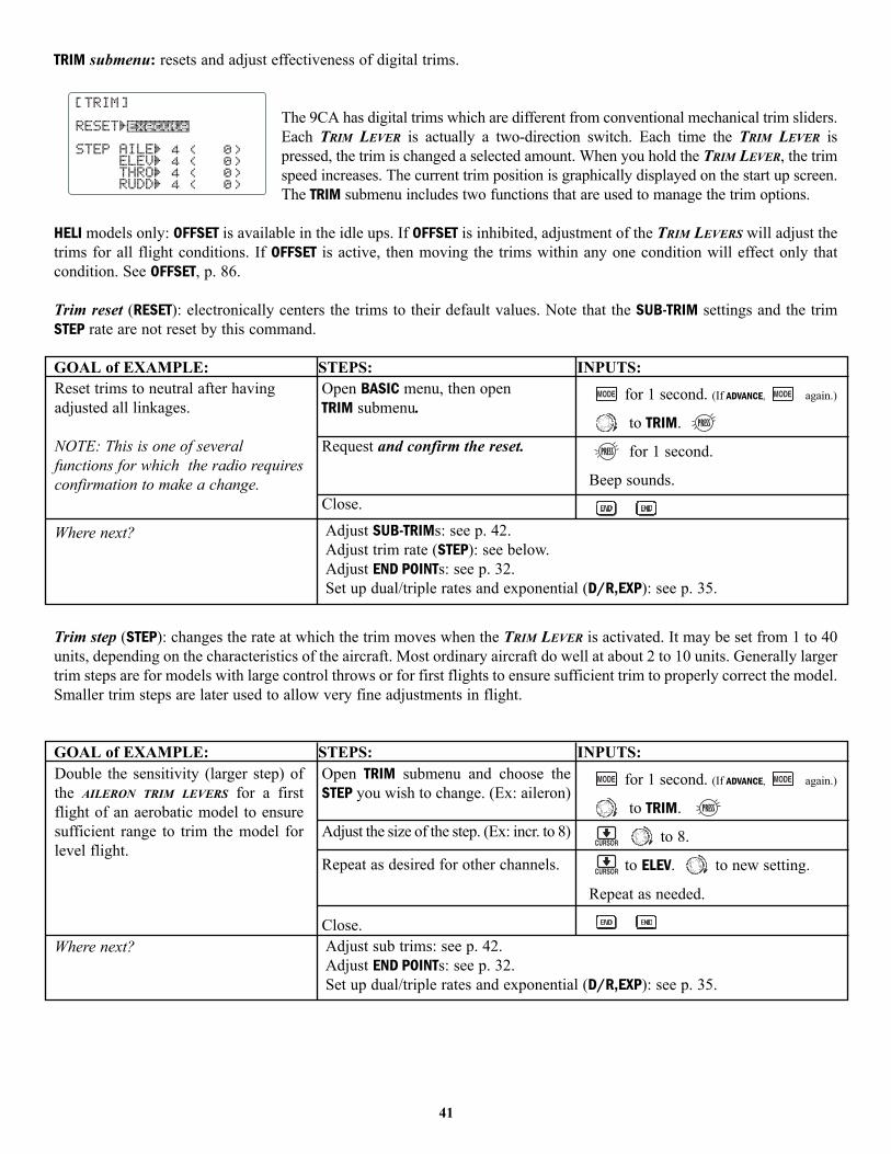
TRIM submenu: resets and adjust effectiveness of digital trims.
The 9CA has digital trims which are different from conventional mechanical trim sliders.Each TRIM LEVER is actually a two-direction switch. Each time the TRIM LEVER ispressed, the trim is changed a selected amount. When you hold the TRIM LEVER, the trimspeed increases. The current trim position is graphically displayed on the start up screen.The TRIM submenu includes two functions that are used to manage the trim options.
HELI models only: OFFSET is available in the idle ups. If OFFSET is inhibited, adjustment of the TRIM LEVERS will adjust thetrims for all flight conditions. If OFFSET is active, then moving the trims within any one condition will effect only thatcondition. See OFFSET, p. 86.
Trim reset (RESET): electronically centers the trims to their default values. Note that the SUB-TRIM settings and the trimSTEP rate are not reset by this command.
GOAL of EXAMPLE: STEPS: INPUTS:
Trim step (STEP): changes the rate at which the trim moves when the TRIM LEVER is activated. It may be set from 1 to 40units, depending on the characteristics of the aircraft. Most ordinary aircraft do well at about 2 to 10 units. Generally largertrim steps are for models with large control throws or for first flights to ensure sufficient trim to properly correct the model.Smaller trim steps are later used to allow very fine adjustments in flight.
GOAL of EXAMPLE: STEPS: INPUTS:
41
Reset trims to neutral after havingadjusted all linkages.
NOTE: This is one of severalfunctions for which the radio requiresconfirmation to make a change.
Where next?
Open BASIC menu, then open TRIM submenu.
Request and confirm the reset.
Close.
for 1 second. (If ADVANCE, again.)
to TRIM.
for 1 second.
Beep sounds.
Adjust SUB-TRIMs: see p. 42.Adjust trim rate (STEP): see below.Adjust END POINTs: see p. 32.Set up dual/triple rates and exponential (D/R,EXP): see p. 35.
Double the sensitivity (larger step) ofthe AILERON TRIM LEVERS for a firstflight of an aerobatic model to ensuresufficient range to trim the model forlevel flight.
Where next?
Open TRIM submenu and choose theSTEP you wish to change. (Ex: aileron)
Adjust the size of the step. (Ex: incr. to 8)
Repeat as desired for other channels.
Close.
for 1 second. (If ADVANCE, again.)
to TRIM.
to 8.
to ELEV. to new setting.
Repeat as needed.
Adjust sub trims: see p. 42.Adjust END POINTs: see p. 32.Set up dual/triple rates and exponential (D/R,EXP): see p. 35.
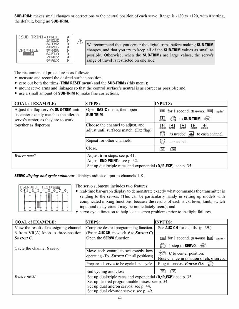
SUB-TRIM: makes small changes or corrections to the neutral position of each servo. Range is -120 to +120, with 0 setting,the default, being no SUB-TRIM.
The recommended procedure is as follows:• measure and record the desired surface position;• zero out both the trims (TRIM RESET menu) and the SUB-TRIMs (this menu);• mount servo arms and linkages so that the control surface’s neutral is as correct as possible; and• use a small amount of SUB-TRIM to make fine corrections.
GOAL of EXAMPLE: STEPS: INPUTS:
SERVO display and cycle submenu: displays radio's output to channels 1-8.
The servo submenu includes two features:• real-time bar-graph display to demonstrate exactly what commands the transmitter is
sending to the servos. (This can be particularly handy in setting up models withcomplicated mixing functions, because the results of each stick, lever, knob, switchinput and delay circuit may be immediately seen.); and
• servo cycle function to help locate servo problems prior to in-flight failures.
GOAL of EXAMPLE: STEPS: INPUTS:
We recommend that you center the digital trims before making SUB-TRIMchanges, and that you try to keep all of the SUB-TRIM values as small aspossible. Otherwise, when the SUB-TRIMs are large values, the servo'srange of travel is restricted on one side.
42
Adjust the flap servo’s SUB-TRIM untilits center exactly matches the aileronservo’s center, as they are to worktogether as flaperons.
Where next?
Open BASIC menu, then open SUB-TRIM.
Choose the channel to adjust, andadjust until surfaces match. (Ex: flap)
Repeat for other channels.
Close.
for 1 second. (If ADVANCE, again.)
to SUB-TRIM.
as needed. to each channel,
as needed.
Adjust trim steps: see p. 41.Adjust END POINTs: see p. 32.Set up dual/triple rates and exponential (D/R,EXP): see p. 35.
View the result of reassigning channel6 from VR(A) knob to three-positionSWITCH C.
Cycle the channel 6 servo.
Where next?
Complete desired programming function.(Ex: in AUX-CH, move ch. 6 to SWITCH C)Open the SERVO function.
Move each control to see exactly howoperating. (Ex: SWITCH C in all positions)
Prepare all servos to be cycled and cycle.
End cycling and close.
See AUX-CH for details. (p. 39.)
for 1 second. (If ADVANCE, again.)
1 step to SERVO.
C to center position.Note change in position of ch. 6 servo.Plug in servos. POWER ON.
Set up dual/triple rates and exponential (D/R,EXP): see p. 35.Set up desired programmable mixes: see p. 54.Set up dual aileron servos: see p. 44.Set up dual elevator servos: see p. 49.
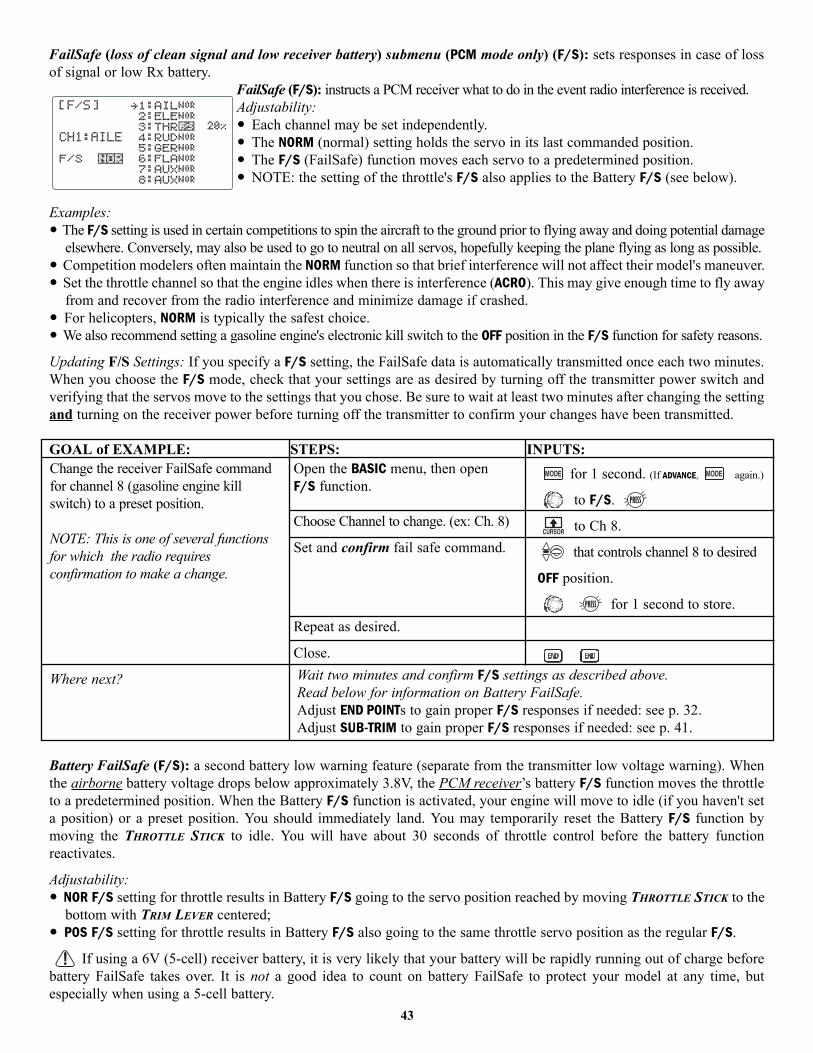
FailSafe (loss of clean signal and low receiver battery) submenu (PCM mode only) (F/S): sets responses in case of lossof signal or low Rx battery.
FailSafe (F/S): instructs a PCM receiver what to do in the event radio interference is received.Adjustability:• Each channel may be set independently.• The NORM (normal) setting holds the servo in its last commanded position.• The F/S (FailSafe) function moves each servo to a predetermined position.• NOTE: the setting of the throttle's F/S also applies to the Battery F/S (see below).
Examples:• The F/S setting is used in certain competitions to spin the aircraft to the ground prior to flying away and doing potential damage
elsewhere. Conversely, may also be used to go to neutral on all servos, hopefully keeping the plane flying as long as possible.• Competition modelers often maintain the NORM function so that brief interference will not affect their model's maneuver.• Set the throttle channel so that the engine idles when there is interference (ACRO). This may give enough time to fly away
from and recover from the radio interference and minimize damage if crashed.• For helicopters, NORM is typically the safest choice.• We also recommend setting a gasoline engine's electronic kill switch to the OFF position in the F/S function for safety reasons.
Updating F/S Settings: If you specify a F/S setting, the FailSafe data is automatically transmitted once each two minutes.When you choose the F/S mode, check that your settings are as desired by turning off the transmitter power switch andverifying that the servos move to the settings that you chose. Be sure to wait at least two minutes after changing the settingand turning on the receiver power before turning off the transmitter to confirm your changes have been transmitted.
GOAL of EXAMPLE: STEPS: INPUTS:
Battery FailSafe (F/S): a second battery low warning feature (separate from the transmitter low voltage warning). Whenthe airborne battery voltage drops below approximately 3.8V, the PCM receiver’s battery F/S function moves the throttleto a predetermined position. When the Battery F/S function is activated, your engine will move to idle (if you haven't seta position) or a preset position. You should immediately land. You may temporarily reset the Battery F/S function bymoving the THROTTLE STICK to idle. You will have about 30 seconds of throttle control before the battery functionreactivates.
Adjustability:• NOR F/S setting for throttle results in Battery F/S going to the servo position reached by moving THROTTLE STICK to the
bottom with TRIM LEVER centered;• POS F/S setting for throttle results in Battery F/S also going to the same throttle servo position as the regular F/S.
If using a 6V (5-cell) receiver battery, it is very likely that your battery will be rapidly running out of charge beforebattery FailSafe takes over. It is not a good idea to count on battery FailSafe to protect your model at any time, butespecially when using a 5-cell battery.
43
Change the receiver FailSafe commandfor channel 8 (gasoline engine killswitch) to a preset position.
NOTE: This is one of several functionsfor which the radio requiresconfirmation to make a change.
Where next?
Open the BASIC menu, then open F/S function.
Choose Channel to change. (ex: Ch. 8)
Set and confirm fail safe command.
Repeat as desired.
Close.
for 1 second. (If ADVANCE, again.)
to F/S.
to Ch 8.
that controls channel 8 to desired
OFF position.
for 1 second to store.
Wait two minutes and confirm F/S settings as described above.Read below for information on Battery FailSafe.Adjust END POINTs to gain proper F/S responses if needed: see p. 32.Adjust SUB-TRIM to gain proper F/S responses if needed: see p. 41.
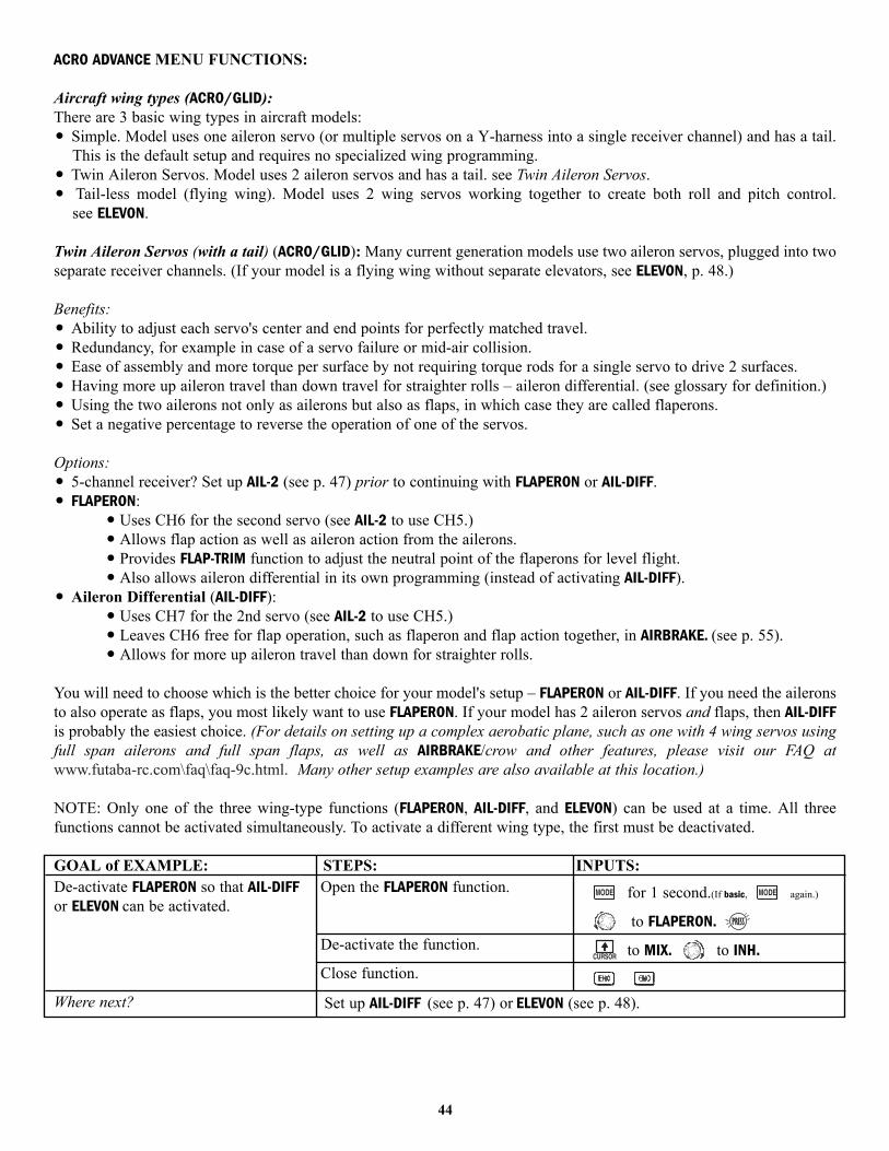
ACRO ADVANCE MENU FUNCTIONS:
Aircraft wing types (ACRO/GLID):There are 3 basic wing types in aircraft models:• Simple. Model uses one aileron servo (or multiple servos on a Y-harness into a single receiver channel) and has a tail.
This is the default setup and requires no specialized wing programming.• Twin Aileron Servos. Model uses 2 aileron servos and has a tail. see Twin Aileron Servos.• Tail-less model (flying wing). Model uses 2 wing servos working together to create both roll and pitch control.
see ELEVON.
Twin Aileron Servos (with a tail) (ACRO/GLID): Many current generation models use two aileron servos, plugged into twoseparate receiver channels. (If your model is a flying wing without separate elevators, see ELEVON, p. 48.)
Benefits:• Ability to adjust each servo's center and end points for perfectly matched travel.• Redundancy, for example in case of a servo failure or mid-air collision.• Ease of assembly and more torque per surface by not requiring torque rods for a single servo to drive 2 surfaces.• Having more up aileron travel than down travel for straighter rolls – aileron differential. (see glossary for definition.)• Using the two ailerons not only as ailerons but also as flaps, in which case they are called flaperons.• Set a negative percentage to reverse the operation of one of the servos.
Options:• 5-channel receiver? Set up AIL-2 (see p. 47) prior to continuing with FLAPERON or AIL-DIFF. • FLAPERON:
• Uses CH6 for the second servo (see AIL-2 to use CH5.)• Allows flap action as well as aileron action from the ailerons.• Provides FLAP-TRIM function to adjust the neutral point of the flaperons for level flight.• Also allows aileron differential in its own programming (instead of activating AIL-DIFF).
• Aileron Differential (AIL-DIFF): • Uses CH7 for the 2nd servo (see AIL-2 to use CH5.)• Leaves CH6 free for flap operation, such as flaperon and flap action together, in AIRBRAKE. (see p. 55).• Allows for more up aileron travel than down for straighter rolls.
You will need to choose which is the better choice for your model's setup – FLAPERON or AIL-DIFF. If you need the aileronsto also operate as flaps, you most likely want to use FLAPERON. If your model has 2 aileron servos and flaps, then AIL-DIFFis probably the easiest choice. (For details on setting up a complex aerobatic plane, such as one with 4 wing servos usingfull span ailerons and full span flaps, as well as AIRBRAKE/crow and other features, please visit our FAQ at www.futaba-rc.com\faq\faq-9c.html. Many other setup examples are also available at this location.)
NOTE: Only one of the three wing-type functions (FLAPERON, AIL-DIFF, and ELEVON) can be used at a time. All threefunctions cannot be activated simultaneously. To activate a different wing type, the first must be deactivated.
GOAL of EXAMPLE: STEPS: INPUTS:
44
De-activate FLAPERON so that AIL-DIFFor ELEVON can be activated.
Where next?
Open the FLAPERON function.
De-activate the function.
Close function.
for 1 second.(If basic, again.)
to FLAPERON.
to MIX. to INH.
Set up AIL-DIFF (see p. 47) or ELEVON (see p. 48).
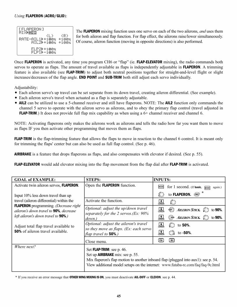
Using FLAPERON (ACRO/GLID):
The FLAPERON mixing function uses one servo on each of the two ailerons, and uses themfor both aileron and flap function. For flap effect, the ailerons raise/lower simultaneously.Of course, aileron function (moving in opposite directions) is also performed.
Once FLAPERON is activated, any time you program CH6 or “flap” (ie. FLAP-ELEVATOR mixing), the radio commands bothservos to operate as flaps. The amount of travel available as flaps is independently adjustable in FLAPERON. A trimmingfeature is also available (see FLAP-TRIM) to adjust both neutral positions together for straight-and-level flight or slightincreases/decreases of the flap angle. END POINT and SUB-TRIM both still adjust each servo individually.
Adjustability:• Each aileron servo's up travel can be set separate from its down travel, creating aileron differential. (See example).• Each aileron servo's travel when actuated as a flap is separately adjustable.• AIL2 can be utilized to use a 5-channel receiver and still have flaperons. NOTE: The AIL2 function only commands the
channel 5 servo to operate with the aileron servo as ailerons, and to obey the primary flap control (travel adjusted inFLAP-TRIM.) It does not provide full flap mix capability as when using a 6+ channel receiver and channel 6.
NOTE: Activating flaperons only makes the ailerons work as ailerons and tells the radio how far you want them to moveas flaps IF you then activate other programming that moves them as flaps.
FLAP-TRIM is the flap-trimming feature that allows the flaps to move in reaction to the channel 6 control. It is meant onlyfor trimming the flaps' center but can also be used as full flap control. (See p. 46).
AIRBRAKE is a feature that drops flaperons as flaps, and also compensates with elevator if desired. (See p. 55).
FLAP-ELEVATOR would add elevator mixing into the flap movement from the flap dial after FLAP-TRIM is activated.
GOAL of EXAMPLE: STEPS: INPUTS:
* If you receive an error message that OTHER WING MIXING IS ON, you must deactivate AIL-DIFF or ELEVON. see p. 44.
45
Activate twin aileron servos, FLAPERON.
Input 10% less down travel than uptravel (aileron differential) within theFLAPERON programming. (Decrease rightaileron’s down travel to 90%, decreaseleft aileron's down travel to 90%.)
Adjust total flap travel available to50% of aileron travel available.
Where next?
Open the FLAPERON function.
Activate the function.
Optional: adjust the up/down travelseparately for the 2 servos.(Ex: 90%down.)Optional: adjust the aileron's travelso they move as flaps. (Ex: each servoflap travel to 50%.)
Close menu.
for 1 second. (If basic, again.)
to FLAPERON. *
AILERON STICK. to 90%.
AILERON STICK. to 90%.
to 50%.
to -50%.
Set FLAP-TRIM: see p. 46.Set up AIRBRAKE mix: see p. 55.Mix flaperon's flap motion to another inboard flap (plugged into aux1): see p. 54.View additional model setups on the internet: www.futaba-rc.com/faq/faq-9c.html

Using FLAP-TRIM (camber) to adjust flaperons: (ACRO/GLID)FLAP-TRIM assigns the primary flaperon control [defaults to VR(A)] to allow trimming inflight of the flap action of flaperons. (Note: even if FLAP-TRIM is made active with AIL-DIFF,it will not have any effect. The ONLY function that allows control of the ailerons as flapsin the AIL-DIFF configuration is AIRBRAKE.) Most modelers use AIRBRAKE, or programmablemixes, to move the flaps to a specified position via movement of a switch.
FLAP-TRIM may also be used as the primary flap control in flight. By doing so, you canassign CH6 to a 3-position switch, with a "spoileron", neutral, and "flaperon" position, and even adjust the percentage traveledas flaperon/spoileron by changing the Flap Trim travel. (Note that there is only one setting, not independent settings for up anddown travel.)
46
Add FLAP-TRIM to allow the model'sailerons to be trimmed together asflaps at any time during the flight,with a maximum travel of 5% of thetotal flap travel set in FLAPERON.
Where next?
Open the FLAP-TRIM function.
Adjust the travel available to theflaperons when turning the CH6 DIAL.(Ex: 5%).Optional: Use as total flap control.Reassign CH6’s primary control inAUX-CH to your desired flap control.(Ex: right slider)
Close menu.
for 1 second.(If basic, again.)
to FLAP-TRIM.
to 5%.
to 50%.
to AUX-CH.
to CH6. to Vr-E.
Adjust individual servo's SUB-TRIMs: see p. 41 and END POINTs: see p. 32.Set up AIRBRAKE mix: see p. 55 and ELEV-FLAP mix: see p. 54.Mix flaperon's flap movement to an additional inboard flap (plugged into aux1): see p. 54.View additional model setups on the internet: www.futaba-rc.com\faq\faq-9c.html.
The function is automatically activated with FLAPERON; however, the default travel is 0.
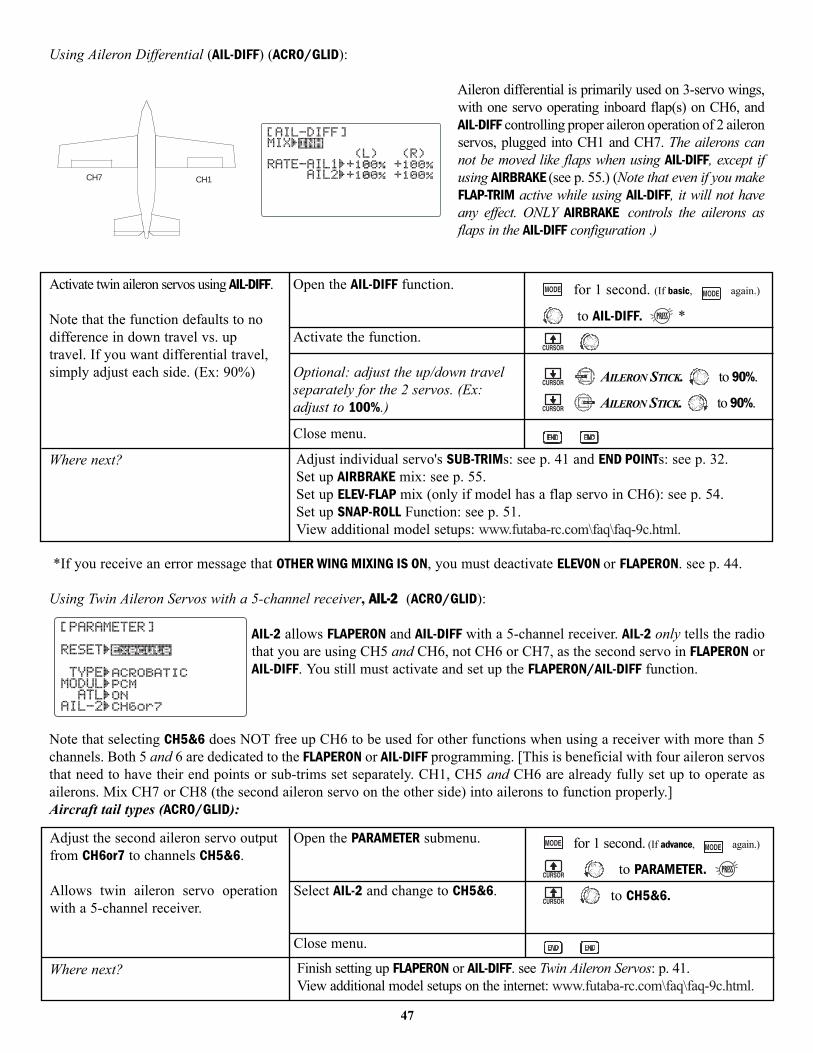
Using Aileron Differential (AIL-DIFF) (ACRO/GLID):
Aileron differential is primarily used on 3-servo wings,with one servo operating inboard flap(s) on CH6, andAIL-DIFF controlling proper aileron operation of 2 aileronservos, plugged into CH1 and CH7. The ailerons cannot be moved like flaps when using AIL-DIFF, except ifusing AIRBRAKE (see p. 55.) (Note that even if you makeFLAP-TRIM active while using AIL-DIFF, it will not haveany effect. ONLY AIRBRAKE controls the ailerons asflaps in the AIL-DIFF configuration .)
*If you receive an error message that OTHER WING MIXING IS ON, you must deactivate ELEVON or FLAPERON. see p. 44.
Using Twin Aileron Servos with a 5-channel receiver, AAIILL--22 (ACRO/GLID):
AIL-2 allows FLAPERON and AIL-DIFF with a 5-channel receiver. AIL-2 only tells the radiothat you are using CH5 and CH6, not CH6 or CH7, as the second servo in FLAPERON orAIL-DIFF. You still must activate and set up the FLAPERON/AIL-DIFF function.
Note that selecting CH5&6 does NOT free up CH6 to be used for other functions when using a receiver with more than 5channels. Both 5 and 6 are dedicated to the FLAPERON or AIL-DIFF programming. [This is beneficial with four aileron servosthat need to have their end points or sub-trims set separately. CH1, CH5 and CH6 are already fully set up to operate asailerons. Mix CH7 or CH8 (the second aileron servo on the other side) into ailerons to function properly.]Aircraft tail types (ACRO/GLID):
CH7 CH1
47
Activate twin aileron servos using AIL-DIFF.
Note that the function defaults to nodifference in down travel vs. uptravel. If you want differential travel,simply adjust each side. (Ex: 90%)
Where next?
Open the AIL-DIFF function.
Activate the function.
Optional: adjust the up/down travelseparately for the 2 servos. (Ex:adjust to 100%.)
Close menu.
for 1 second. (If basic, again.)
to AIL-DIFF. *
AILERON STICK. to 90%.
AILERON STICK. to 90%.
Adjust individual servo's SUB-TRIMs: see p. 41 and END POINTs: see p. 32.Set up AIRBRAKE mix: see p. 55.Set up ELEV-FLAP mix (only if model has a flap servo in CH6): see p. 54.Set up SNAP-ROLL Function: see p. 51.View additional model setups: www.futaba-rc.com\faq\faq-9c.html.
Adjust the second aileron servo outputfrom CH6or7 to channels CH5&6.
Allows twin aileron servo operationwith a 5-channel receiver.
Where next?
Open the PARAMETER submenu.
Select AIL-2 and change to CH5&6.
Close menu.
for 1 second. (If advance, again.)
to PARAMETER.
to CH5&6.
Finish setting up FLAPERON or AIL-DIFF. see Twin Aileron Servos: p. 41.View additional model setups on the internet: www.futaba-rc.com\faq\faq-9c.html.
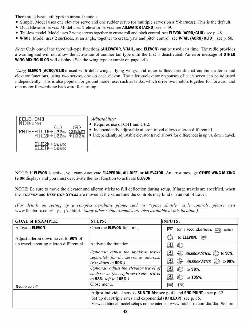
There are 4 basic tail types in aircraft models:• Simple. Model uses one elevator servo and one rudder servo (or multiple servos on a Y-harness). This is the default.• Dual Elevator servos. Model uses 2 elevator servos. see AILEVATOR (ACRO) see p. 49.• Tail-less model. Model uses 2 wing servos together to create roll and pitch control. see ELEVON (ACRO/GLID). see p. 48.• V-TAIL. Model uses 2 surfaces, at an angle, together to create yaw and pitch control. see V-TAIL (ACRO/GLID). see p. 50.
Note: Only one of the three tail-type functions (AILEVATOR, V-TAIL, and ELEVON) can be used at a time. The radio providesa warning and will not allow the activation of another tail type until the first is deactivated. An error message of OTHERWING MIXING IS ON will display. (See the wing type example on page 44.)
Using ELEVON (ACRO/GLID): used with delta wings, flying wings, and other tailless aircraft that combine aileron andelevator functions, using two servos, one on each elevon. The aileron/elevator responses of each servo can be adjustedindependently. This is also popular for ground model use, such as tanks, which drive two motors together for forward, andone motor forward/one backward for turning.
Adjustability:• Requires use of CH1 and CH2.• Independently adjustable aileron travel allows aileron differential.• Independently adjustable elevator travel allows for differences in up vs. down travel.
NOTE: If ELEVON is active, you cannot activate FLAPERON, AIL-DIFF, or AILEVATOR. An error message OTHER WING MIXINGIS ON displays and you must deactivate the last function to activate ELEVON.
NOTE: Be sure to move the elevator and aileron sticks to full deflection during setup. If large travels are specified, whenthe AILERON and ELEVATOR STICKS are moved at the same time the controls may bind or run out of travel.
(For details on setting up a complex aerobatic plane, such as “space shuttle” style controls, please visit www.futaba-rc.com\faq\faq-9c.html. Many other setup examples are also available at this location.)
GOAL of EXAMPLE: STEPS: INPUTS:
48
Activate ELEVON.
Adjust aileron down travel to 90% ofup travel, creating aileron differential.
Where next?
Open the ELEVON function.
Activate the function.
Optional: adjust the up/down travelseparately for the servos as ailerons.(Ex: down to 90%.)Optional: adjust the elevator travel ofeach servo. (Ex: right servo elev. travelto 98%, left to 105%.)Close menu.
for 1 second.(If basic, again.)
to ELEVON.
AILERON STICK. to 90%.
AILERON STICK to 90%.
to 98%.
to 105%.
Adjust individual servo's SUB-TRIMs: see p. 41 and END POINTs: see p. 32.Set up dual/triple rates and exponential (D/R,EXP): see p. 35.View additional model setups on the internet: www.futaba-rc.com\faq\faq-9c.html
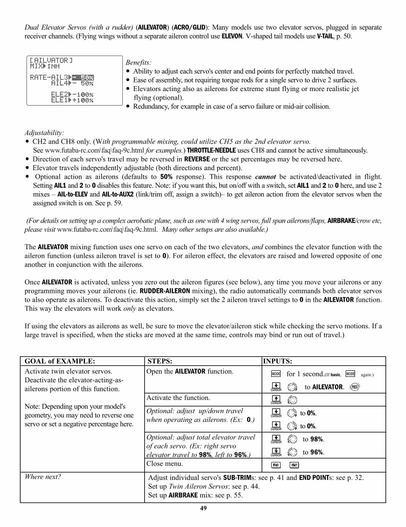
Dual Elevator Servos (with a rudder) (AILEVATOR) (ACRO/GLID): Many models use two elevator servos, plugged in separatereceiver channels. (Flying wings without a separate aileron control use ELEVON. V-shaped tail models use V-TAIL, p. 50.
Benefits:• Ability to adjust each servo's center and end points for perfectly matched travel.• Ease of assembly, not requiring torque rods for a single servo to drive 2 surfaces.• Elevators acting also as ailerons for extreme stunt flying or more realistic jet
flying (optional).• Redundancy, for example in case of a servo failure or mid-air collision.
Adjustability:• CH2 and CH8 only. (With programmable mixing, could utilize CH5 as the 2nd elevator servo.
See www.futaba-rc.com\faq\faq-9c.html for examples.) THROTTLE-NEEDLE uses CH8 and cannot be active simultaneously.• Direction of each servo's travel may be reversed in REVERSE or the set percentages may be reversed here.• Elevator travels independently adjustable (both directions and percent).• Optional action as ailerons (defaults to 50% response). This response cannot be activated/deactivated in flight.
Setting AIL1 and 2 to 0 disables this feature. Note: if you want this, but on/off with a switch, set AIL1 and 2 to 0 here, and use 2mixes – AIL-to-ELEV and AIL-to-AUX2 (link/trim off, assign a switch)– to get aileron action from the elevator servos when theassigned switch is on. See p. 59.
(For details on setting up a complex aerobatic plane, such as one with 4 wing servos, full span ailerons/flaps, AIRBRAKE/crow etc,please visit www.futaba-rc.com\faq\faq-9c.html. Many other setups are also available.)
The AILEVATOR mixing function uses one servo on each of the two elevators, and combines the elevator function with theaileron function (unless aileron travel is set to 0). For aileron effect, the elevators are raised and lowered opposite of oneanother in conjunction with the ailerons.
Once AILEVATOR is activated, unless you zero out the aileron figures (see below), any time you move your ailerons or anyprogramming moves your ailerons (ie. RUDDER-AILERON mixing), the radio automatically commands both elevator servosto also operate as ailerons. To deactivate this action, simply set the 2 aileron travel settings to 0 in the AILEVATOR function.This way the elevators will work only as elevators.
If using the elevators as ailerons as well, be sure to move the elevator/aileron stick while checking the servo motions. If alarge travel is specified, when the sticks are moved at the same time, controls may bind or run out of travel.)
GOAL of EXAMPLE: STEPS: INPUTS:
49
Activate twin elevator servos.Deactivate the elevator-acting-as-ailerons portion of this function.
Note: Depending upon your model'sgeometry, you may need to reverse oneservo or set a negative percentage here.
Where next?
Open the AILEVATOR function.
Activate the function.
Optional: adjust up/down travelwhen operating as ailerons. (Ex: 0.)
Optional: adjust total elevator travelof each servo. (Ex: right servoelevator travel to 98%, left to 96%.)Close menu.
for 1 second.(If basic, again.)
to AILEVATOR.
to 0%.
to 0%.
to 98%.
to 96%.
Adjust individual servo's SUB-TRIMs: see p. 41 and END POINTs: see p. 32.Set up Twin Aileron Servos: see p. 44.Set up AIRBRAKE mix: see p. 55.
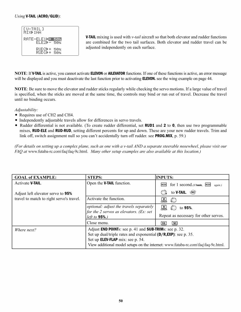
Using V-TAIL (ACRO/GLID):
V-TAIL mixing is used with v-tail aircraft so that both elevator and rudder functionsare combined for the two tail surfaces. Both elevator and rudder travel can beadjusted independently on each surface.
NOTE: If V-TAIL is active, you cannot activate ELEVON or AILEVATOR functions. If one of these functions is active, an error messagewill be displayed and you must deactivate the last function prior to activating ELEVON. see the wing example on page 44.
NOTE: Be sure to move the elevator and rudder sticks regularly while checking the servo motions. If a large value of travelis specified, when the sticks are moved at the same time, the controls may bind or run out of travel. Decrease the traveluntil no binding occurs.
Adjustability:• Requires use of CH2 and CH4.• Independently adjustable travels allow for differences in servo travels.• Rudder differential is not available. (To create rudder differential, set RUD1 and 2 to 0, then use two programmable
mixes, RUD-ELE and RUD-RUD, setting different percents for up and down. These are your new rudder travels. Trim andlink off, switch assignment null so you can’t accidentally turn off rudder. see PROG.MIX, p. 59.)
(For details on setting up a complex plane, such as one with a v-tail AND a separate steerable nosewheel, please visit ourFAQ at www.futaba-rc.com\faq\faq-9c.html. Many other setup examples are also available at this location.)
GOAL of EXAMPLE: STEPS: INPUTS:
50
Activate V-TAIL.
Adjust left elevator servo to 95%travel to match to right servo's travel.
Where next?
Open the V-TAIL function.
Activate the function.
optional: adjust the travels separatelyfor the 2 servos as elevators. (Ex: setleft to 95%.)Close menu.
for 1 second.(If basic, again.)
to V-TAIL.
to 95%.
Repeat as necessary for other servos.
Adjust END POINTs: see p. 41 and SUB-TRIMs: see p. 32.Set up dual/triple rates and exponential (D/R,EXP): see p. 35.Set up ELEV-FLAP mix: see p. 54.View additional model setups on the internet: www.futaba-rc.com\faq\faq-9c.html.
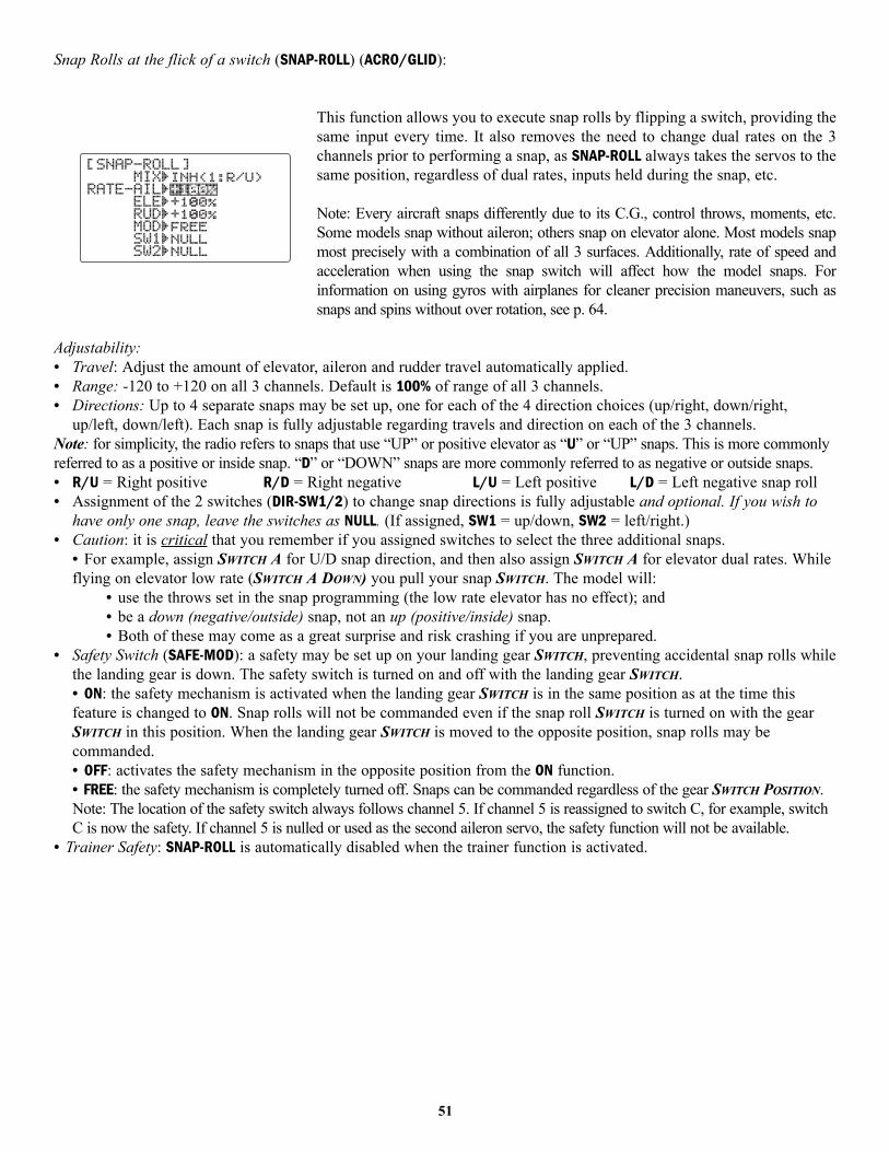
Snap Rolls at the flick of a switch (SNAP-ROLL) (ACRO/GLID):
This function allows you to execute snap rolls by flipping a switch, providing thesame input every time. It also removes the need to change dual rates on the 3channels prior to performing a snap, as SNAP-ROLL always takes the servos to thesame position, regardless of dual rates, inputs held during the snap, etc.
Note: Every aircraft snaps differently due to its C.G., control throws, moments, etc.Some models snap without aileron; others snap on elevator alone. Most models snapmost precisely with a combination of all 3 surfaces. Additionally, rate of speed andacceleration when using the snap switch will affect how the model snaps. Forinformation on using gyros with airplanes for cleaner precision maneuvers, such assnaps and spins without over rotation, see p. 64.
Adjustability:• Travel: Adjust the amount of elevator, aileron and rudder travel automatically applied. • Range: -120 to +120 on all 3 channels. Default is 100% of range of all 3 channels.• Directions: Up to 4 separate snaps may be set up, one for each of the 4 direction choices (up/right, down/right,
up/left, down/left). Each snap is fully adjustable regarding travels and direction on each of the 3 channels. Note: for simplicity, the radio refers to snaps that use “UP” or positive elevator as “U” or “UP” snaps. This is more commonlyreferred to as a positive or inside snap. “D” or “DOWN” snaps are more commonly referred to as negative or outside snaps.• R/U = Right positive R/D = Right negative L/U = Left positive L/D = Left negative snap roll• Assignment of the 2 switches (DIR-SW1/2) to change snap directions is fully adjustable and optional. If you wish to
have only one snap, leave the switches as NULL. (If assigned, SW1 = up/down, SW2 = left/right.) • Caution: it is critical that you remember if you assigned switches to select the three additional snaps.
• For example, assign SWITCH A for U/D snap direction, and then also assign SWITCH A for elevator dual rates. Whileflying on elevator low rate (SWITCH A DOWN) you pull your snap SWITCH. The model will:
• use the throws set in the snap programming (the low rate elevator has no effect); and • be a down (negative/outside) snap, not an up (positive/inside) snap.• Both of these may come as a great surprise and risk crashing if you are unprepared.
• Safety Switch (SAFE-MOD): a safety may be set up on your landing gear SWITCH, preventing accidental snap rolls whilethe landing gear is down. The safety switch is turned on and off with the landing gear SWITCH. • ON: the safety mechanism is activated when the landing gear SWITCH is in the same position as at the time thisfeature is changed to ON. Snap rolls will not be commanded even if the snap roll SWITCH is turned on with the gearSWITCH in this position. When the landing gear SWITCH is moved to the opposite position, snap rolls may becommanded. • OFF: activates the safety mechanism in the opposite position from the ON function. • FREE: the safety mechanism is completely turned off. Snaps can be commanded regardless of the gear SWITCH POSITION.Note: The location of the safety switch always follows channel 5. If channel 5 is reassigned to switch C, for example, switchC is now the safety. If channel 5 is nulled or used as the second aileron servo, the safety function will not be available.
• Trainer Safety: SNAP-ROLL is automatically disabled when the trainer function is activated.
51
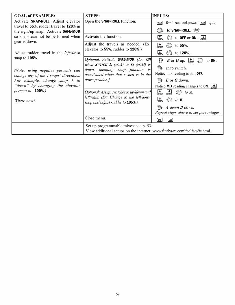
GOAL of EXAMPLE: STEPS: INPUTS:
52
Activate SNAP-ROLL. Adjust elevatortravel to 55%, rudder travel to 120% inthe right/up snap. Activate SAFE-MODso snaps can not be performed whengear is down.
Adjust rudder travel in the left/downsnap to 105%.
(Note: using negative percents canchange any of the 4 snaps’ directions.For example, change snap 1 to“down” by changing the elevatorpercent to –100%.)
Where next?
Open the SNAP-ROLL function.
Activate the function.
Adjust the travels as needed. (Ex:elevator to 55%, rudder to 120%.)
Optional: Activate SAFE-MOD. [Ex: ONwhen SWITCH E (9CA) or G (9CH) isdown, meaning snap function isdeactivated when that switch is in thedown position.]
Optional: Assign switches to up/down andleft/right. (Ex: Change to the left/downsnap and adjust rudder to 105%.)
Close menu.
for 1 second.(If basic, again.)
to SNAP-ROLL.
to OFF or ON.
to 55%.
to 120%.
E or G up. to ON.
snap switch. Notice mix reading is still OFF.
E or G down.Notice MIX reading changes to ON.
to A.
to B.
A down B down.Repeat steps above to set percentages.
Set up programmable mixes: see p. 53.View additional setups on the internet: www.futaba-rc.com\faq\faq-9c.html.
MIXES: the backbone of nearly every functionMixes are special programs within the radio that command one or more channels to act together with input from only onesource, such as a stick, slider or knob.
There are a variety of types of mixes.Types:• Linear: Most mixes are linear. A 100% linear mix tells the slave servo to do exactly what the master servo is doing,
using 100% of the slave channel’s range to do so. An example is FLAPERON – when aileron stick is moved, the flap servois told to move exactly the same amount. A 50% linear mix would tell the slave servo, for example, to move to 50% ofits range when the master’s control is moved 100%. (see p. 54.)
• Offset: An OFFSET mix is a special type of linear mix. When the mix is turned on (usually a flip of a switch), the slaveservo is moved a set percent of its range. An example of this is AIRBRAKE – moving flaps, flaperons, and elevator all toa set position at the flip of a switch. (see p. 55.)
• Curve: Curve mixes are mostly used in helicopters, but may also be used in airplanes and gliders. An example is THROTTLE-NEEDLE mixing, where the in-flight needle’s servo is moved, changing the mixture, as the throttle servo is moved. (see p. 56.)
• Delay: Delay mixes are part of a few very special functions that make the servo move to its desired range more slowly.THROTTLE DELAY (simulates turbine engines, p. 57) and the elevator delay in AIRBRAKE are two examples of this (see p. 55). DELAY in HELI (see p. 87) is another example that slows the servo movement to the trim settings for the otherconditions. The 9C does not offer fully programmable delay mixes.
Essentially every feature in the radio’s programming is really a mix, with all assignments/programming set up and readyto use. Additionally, the 9C ACRO and GLID programs both provide 5 linear and 2 curve fully-programmable mixes (HELIprovides two linear and one curve) that allow you to set up special mixes to resolve flight difficulties, activate additionalfunctions, etc.
Let’s look quickly at a few examples that are features we’ve already covered. This may help to clarify the mix types andthe importance of mixes.
Additional examples:• Exponential is a preprogrammed curve mix that makes the servos’ response more (+) or less (-) sensitive around center
stick (works in conjunction with dual rate, a linear mix that adjusts the total range). see D/R,EXP, p. 35.• IDLE-DOWN and THR-CUT are two OFFSET pre-programmed mixes. These tell the throttle servo, when below a certain point, to
move toward idle an additional set percentage to help close the carburetor. see p. 33.• ELEV-TO-FLAP mixing is a pre-programmed linear mix to move the flaps proportionally to elevator control, helping the model
loop even tighter than it can on elevator alone. (see p. 54.)• THROTTLE-NEEDLE mixing is a curve mix (like PROG.MIX 6 and 7) for proper in-flight needle setup. (see p. 56.)• THROTTLE DELAY mixing is a pre-programmed delay mix that slows down the response of the CH3 servo. (see p. 57.)
Next, we'll get an in-depth look at some pre-programmed mixes (mixes whose channels are predefined by Futaba forsimplicity) we’ve not covered yet, and last, look at the fully-programmable mix types.
53
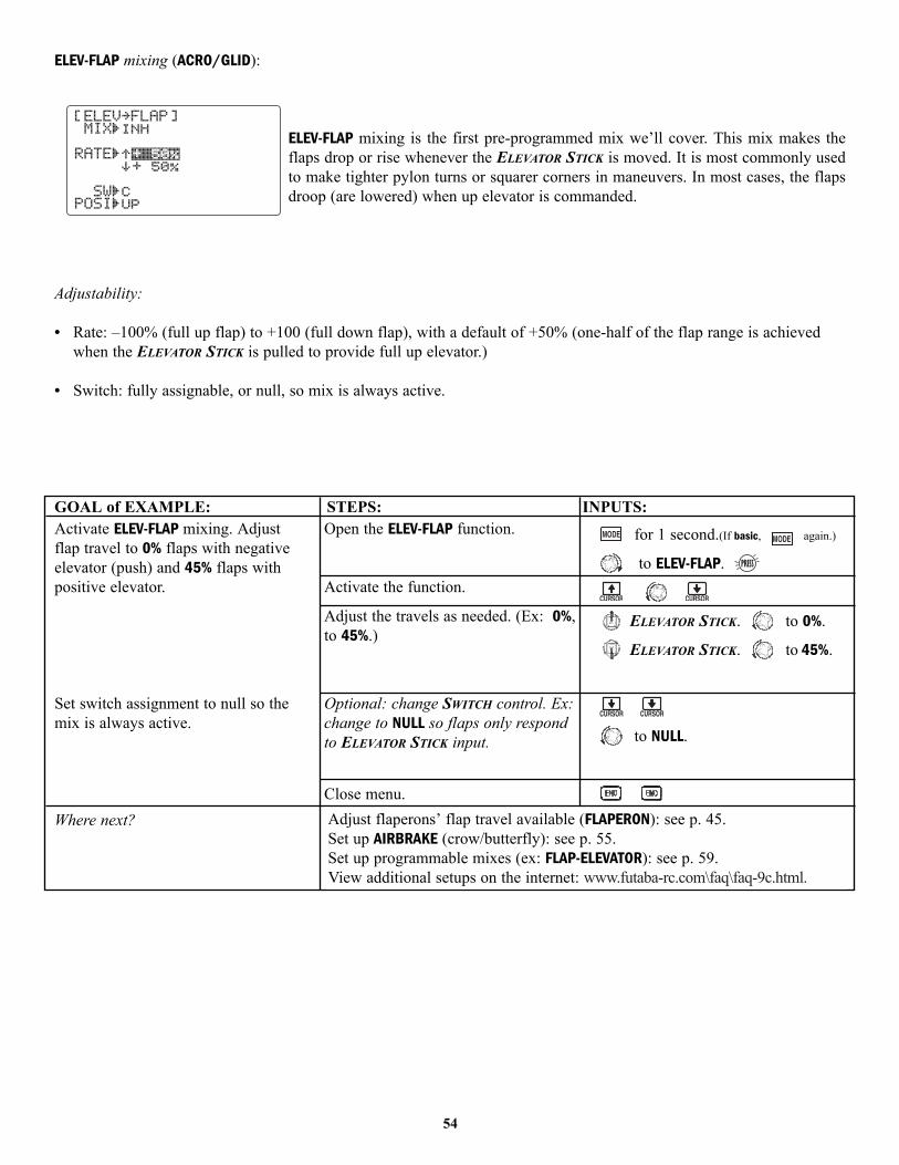
ELEV-FLAP mixing (ACRO/GLID):
ELEV-FLAP mixing is the first pre-programmed mix we’ll cover. This mix makes theflaps drop or rise whenever the ELEVATOR STICK is moved. It is most commonly usedto make tighter pylon turns or squarer corners in maneuvers. In most cases, the flapsdroop (are lowered) when up elevator is commanded.
Adjustability:
• Rate: –100% (full up flap) to +100 (full down flap), with a default of +50% (one-half of the flap range is achievedwhen the ELEVATOR STICK is pulled to provide full up elevator.)
• Switch: fully assignable, or null, so mix is always active.
GOAL of EXAMPLE: STEPS: INPUTS:
54
Activate ELEV-FLAP mixing. Adjustflap travel to 0% flaps with negativeelevator (push) and 45% flaps withpositive elevator.
Set switch assignment to null so themix is always active.
Where next?
Open the ELEV-FLAP function.
Activate the function.
Adjust the travels as needed. (Ex: 0%,to 45%.)
Optional: change SWITCH control. Ex:change to NULL so flaps only respondto ELEVATOR STICK input.
Close menu.
for 1 second.(If basic, again.)
to ELEV-FLAP.
ELEVATOR STICK. to 0%.
ELEVATOR STICK. to 45%.
to NULL.
Adjust flaperons’ flap travel available (FLAPERON): see p. 45.Set up AIRBRAKE (crow/butterfly): see p. 55.Set up programmable mixes (ex: FLAP-ELEVATOR): see p. 59.View additional setups on the internet: www.futaba-rc.com\faq\faq-9c.html.
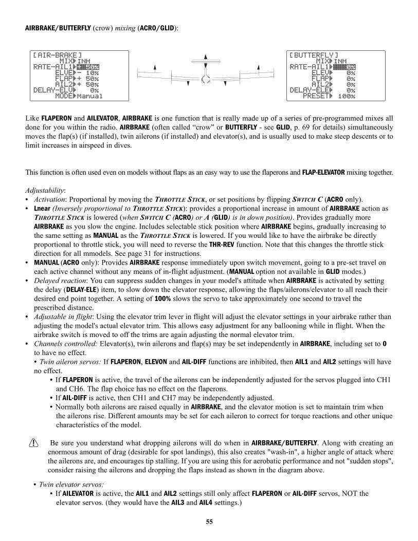
AIRBRAKE/BUTTERFLY (crow) mixing (ACRO/GLID):
Like FLAPERON and AILEVATOR, AIRBRAKE is one function that is really made up of a series of pre-programmed mixes alldone for you within the radio. AIRBRAKE (often called “crow” or BUTTERFLY - see GLID, p. 69 for details) simultaneouslymoves the flap(s) (if installed), twin ailerons (if installed) and elevator(s), and is usually used to make steep descents or tolimit increases in airspeed in dives.
This function is often used even on models without flaps as an easy way to use the flaperons and FLAP-ELEVATOR mixing together.
Adjustability:• Activation: Proportional by moving the THROTTLE STICK, or set positions by flipping SWITCH C (ACRO only). • Lnear (Inversely proportional to THROTTLE STICK): provides a proportional increase in amount of AIRBRAKE action as
THROTTLE STICK is lowered (when SWITCH C (ACRO) or A (GLID) is in down position). Provides gradually moreAIRBRAKE as you slow the engine. Includes selectable stick position where AIRBRAKE begins, gradually increasing tothe same setting as MANUAL as the THROTTLE STICK is lowered. If you would like to have the airbrake be directlyproportional to throttle stick, you will need to reverse the THR-REV function. Note that this changes the throttle stickdirection for all mmodels. See page 31 for instructions.
• MANUAL (ACRO only): Provides AIRBRAKE response immediately upon switch movement, going to a pre-set travel oneach active channel without any means of in-flight adjustment. (MANUAL option not available in GLID modes.)
• Delayed reaction: You can suppress sudden changes in your model's attitude when AIRBRAKE is activated by settingthe delay (DELAY-ELE) item, to slow down the elevator response, allowing the flaps/ailerons/elevator to all reach theirdesired end point together. A setting of 100% slows the servo to take approximately one second to travel theprescribed distance.
• Adjustable in flight: Using the elevator trim lever in flight will adjust the elevator settings in your airbrake rather thanadjusting the model's actual elevator trim. This allows easy adjustment for any ballooning while in flight. When theairbrake switch is moved to off the trims are again adjusting the normal elevator trim.
• Channels controlled: Elevator(s), twin ailerons and flap(s) may be set independently in AIRBRAKE, including set to 0to have no effect. • Twin aileron servos: If FLAPERON, ELEVON and AIL-DIFF functions are inhibited, then AIL1 and AIL2 settings will haveno effect.
• If FLAPERON is active, the travel of the ailerons can be independently adjusted for the servos plugged into CH1and CH6. The flap choice has no effect on the flaperons.
• If AIL-DIFF is active, then CH1 and CH7 may be independently adjusted. • Normally both ailerons are raised equally in AIRBRAKE, and the elevator motion is set to maintain trim when
the ailerons rise. Different amounts may be set for each aileron to correct for torque reactions and other uniquecharacteristics of the model.
Be sure you understand what dropping ailerons will do when in AIRBRAKE/BUTTERFLY. Along with creating anenormous amount of drag (desirable for spot landings), this also creates "wash-in", a higher angle of attack wherethe ailerons are, and encourages tip stalling. If you are using this for aerobatic performance and not "sudden stops",consider raising the ailerons and dropping the flaps instead as shown in the diagram above.
• Twin elevator servos: • If AILEVATOR is active, the AIL1 and AIL2 settings still only affect FLAPERON or AIL-DIFF servos, NOT the
elevator servos. (they would have the AIL3 and AIL4 settings.)
55
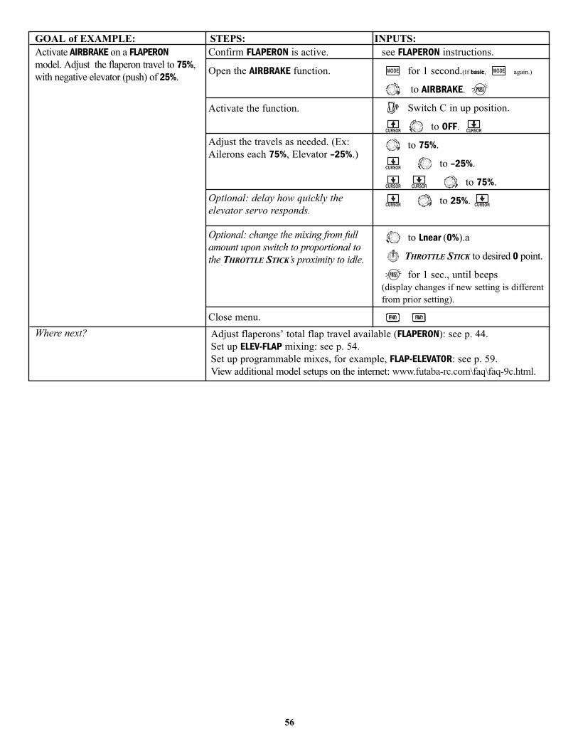
GOAL of EXAMPLE: STEPS: INPUTS:
56
Activate AIRBRAKE on a FLAPERONmodel. Adjust the flaperon travel to 75%,with negative elevator (push) of 25%.
Where next?
Confirm FLAPERON is active.
Open the AIRBRAKE function.
Activate the function.
Adjust the travels as needed. (Ex:Ailerons each 75%, Elevator –25%.)
Optional: delay how quickly theelevator servo responds.
Optional: change the mixing from fullamount upon switch to proportional tothe THROTTLE STICK’s proximity to idle.
Close menu.
see FLAPERON instructions.
for 1 second.(If basic, again.)
to AIRBRAKE.
Switch C in up position.
to OFF.
to 75%.
to –25%.
to 75%.
to 25%.
to Lnear (0%).a
THROTTLE STICK to desired 0 point.
for 1 sec., until beeps (display changes if new setting is differentfrom prior setting).
Adjust flaperons’ total flap travel available (FLAPERON): see p. 44.Set up ELEV-FLAP mixing: see p. 54.Set up programmable mixes, for example, FLAP-ELEVATOR: see p. 59.View additional model setups on the internet: www.futaba-rc.com\faq\faq-9c.html.
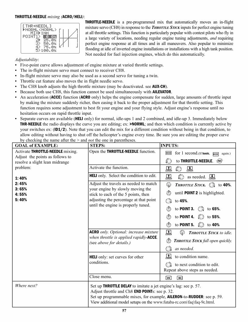
THROTTLE-NEEDLE mixing (ACRO/HELI):THROTTLE-NEEDLE is a pre-programmed mix that automatically moves an in-flightmixture servo (CH8) in response to the THROTTLE STICK inputs for perfect engine tuningat all throttle settings. This function is particularly popular with contest pilots who fly ina large variety of locations, needing regular engine tuning adjustments, and requiringperfect engine response at all times and in all maneuvers. Also popular to minimizeflooding at idle of inverted engine installations or installations with a high tank position.Not needed for fuel injection engines, which do this automatically.
Adjustability:• Five-point curve allows adjustment of engine mixture at varied throttle settings.• The in-flight mixture servo must connect to receiver CH8.• In-flight mixture servo may also be used as a second servo for tuning a twin.• Throttle cut feature also moves the in flight needle servo.• The CH8 knob adjusts the high throttle mixture (may be deactivated. see AUX-CH). • Because both use CH8, this function cannot be used simultaneously with AILEVATOR.• An acceleration (ACCE) function (ACRO only) helps the engine compensate for sudden, large amounts of throttle input
by making the mixture suddenly richer, then easing it back to the proper adjustment for that throttle setting. Thisfunction requires some adjustment to best fit your engine and your flying style. Adjust engine’s response until nohesitation occurs on rapid throttle input.
• Separate curves are available (HELI only) for normal, idle-ups 1 and 2 combined, and idle-up 3. Immediately belowTHR-NEEDLE the radio displays the curve you are editing; ex: >NORML; and then which condition is currently active byyour switches ex: (ID1/2). Note that you can edit the mix for a different condition without being in that condition, toallow editing without having to shut off the helicopter’s engine every time. Be sure you are editing the proper curveby checking the name after the > and not the one in parentheses.
GOAL of EXAMPLE: STEPS: INPUTS:
57
Activate THROTTLE-NEEDLE mixing.Adjust the points as follows toresolve a slight lean midrangeproblem:
1: 40%2: 45%3: 65%4: 55%5: 40%
Where next?
Open the THROTTLE-NEEDLE function.
Activate the function.
HELI only. Select the condition to edit.
Adjust the travels as needed to matchyour engine by slowly moving thestick to each of the 5 points, thenadjusting the percentage at that pointuntil the engine is properly tuned.
ACRO only. Optional: increase mixturewhen throttle is applied rapidly-ACCE.(see above for details.)
HELI only: set curves for otherconditions.
Close menu.
for 1 second.(If basic, again.)
to THROTTLE-NEEDLE.
as needed.
THROTTLE STICK. to 40%.
until POINT 2 is highlighted.
to 45%.
to POINT 3. to 65%.
to POINT 4. to 55%.
to POINT 5. to 40%
THROTTLE STICK to idle.
THROTTLE STICK full open quickly.
as needed.
to condition name.
to next condition to edit.Repeat above steps as needed.
Set up THROTTLE DELAY to imitate a jet engine’s lag: see p. 57.Adjust throttle and Ch8 END POINTs: see p. 32.Set up programmable mixes, for example, AILERON-to-RUDDER: see p. 59.View additional model setups on the www.futaba-rc.com\faq\faq-9c.html.
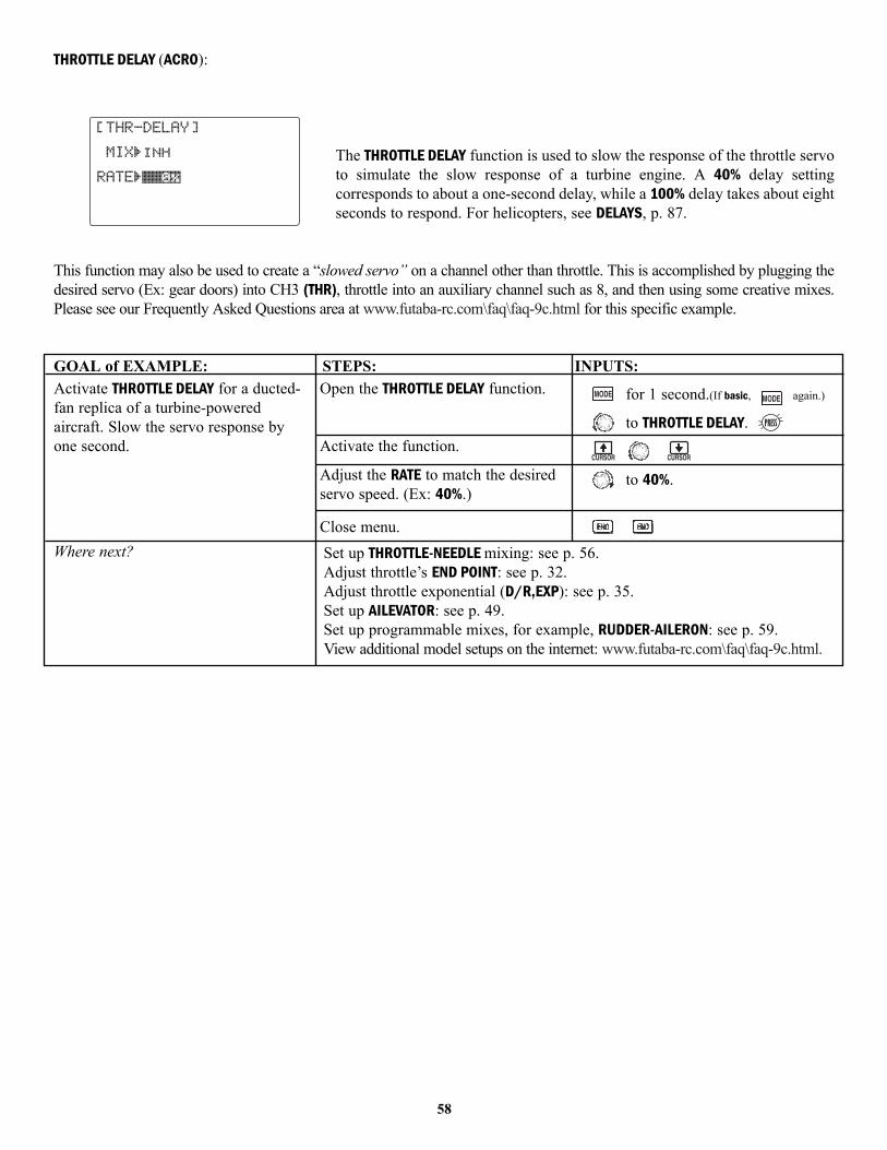
THROTTLE DELAY (ACRO):
The THROTTLE DELAY function is used to slow the response of the throttle servoto simulate the slow response of a turbine engine. A 40% delay settingcorresponds to about a one-second delay, while a 100% delay takes about eightseconds to respond. For helicopters, see DELAYS, p. 87.
This function may also be used to create a “slowed servo” on a channel other than throttle. This is accomplished by plugging thedesired servo (Ex: gear doors) into CH3 (THR), throttle into an auxiliary channel such as 8, and then using some creative mixes.Please see our Frequently Asked Questions area at www.futaba-rc.com\faq\faq-9c.html for this specific example.
GOAL of EXAMPLE: STEPS: INPUTS:
58
Activate THROTTLE DELAY for a ducted-fan replica of a turbine-poweredaircraft. Slow the servo response byone second.
Where next?
Open the THROTTLE DELAY function.
Activate the function.
Adjust the RATE to match the desiredservo speed. (Ex: 40%.)
Close menu.
for 1 second.(If basic, again.)
to THROTTLE DELAY.
to 40%.
Set up THROTTLE-NEEDLE mixing: see p. 56.Adjust throttle’s END POINT: see p. 32.Adjust throttle exponential (D/R,EXP): see p. 35.Set up AILEVATOR: see p. 49.Set up programmable mixes, for example, RUDDER-AILERON: see p. 59.View additional model setups on the internet: www.futaba-rc.com\faq\faq-9c.html.

LINEAR PROGRAMMABLE MIXES (PROG.MIX1-5):
Your 9C contains five separate linear programmable mixes (ACRO and GLID. HELI has 2). (Note that mixer #6-7’s mixingRATEs are set with a 5-point curve. see CURVE MIXES, p. 62.)
There are a variety of reasons you might want to use these mixes. A few are listed here. All of the adjustable parametersare listed below, but don’t let them scare you. For your first few times experimenting with mixes, just turn on the defaultmixes, adjust them how you think they need to be, then use the servo screen to check and see if you were correct. As withall functions, a sample setup follows, step by step, to assist you.
Sample reasons to use linear programmable mixes:• To correct bad tendencies of the aircraft (such as rolling in response to rudder input).• To operate 2 or more servos for a single axis (such as two rudder servos).• To automatically correct for a particular action (such as lowering elevator when flaps are lowered).• To operate a second channel in response to movement in a first channel (such as increasing the amount of smoke oil
in response to more throttle application, but only when the smoke switch is active).• To turn off response of a primary control in certain circumstances (such as simulating one engine flaming-out on a
twin, or throttle-assisted rudder turns, also with a twin).
Adjustability:• ACRO/GLID Defaults: The 5 programmable mixes default to the most frequently used mixes for simplicity. If you want
to use one of these mixes, simply select that mix number so that the master and slave servos are already selected foryou. (HELI mixes default to ail-to-rudd and elev-to-pitch.)
• PROG.MIX1 aileron-to-rudder for coordinated turns• PROG.MIX2 elevator-to-flap for tighter loops• PROG.MIX3 flap-to-elevator to compensate pitching with flaps• PROG.MIX4 throttle-to-rudder ground handling compensation• PROG.MIX5 rudder-to-aileron roll coupling compensation
• Channels available to mix: All five mixes may use any combination of CH1-8. (CH9 is not proportional and cannot bemixed.) Offset and dials may also be set to the master channels. (see below.)
• Master: the controlling channel. The channel whose movement is followed by the slave channel.• Another channel: Most mixes follow a control channel. (Ex: rudder-to-ailerons, 25%, no switch, corrects roll coupling.)
MASTER SLAVE LINK TRIM SWITCH POSITION RATE OFFSETRUDD AILE ON OFF ANY NULL 25% 0
• Offset as master: To create an OFFSET mix, set the master as OFST. (Ex: move flaperons as flaps 20% of their totalthrow when SWITCH C is in down position.)
MASTER SLAVE LINK TRIM SWITCH POSITION RATE OFFSETOFST FLAP ON N/A C DOWN 20% 0
59

• Dial as master: To directly effect one servo’s position by moving a dial, set the master as the desired dial. (Ex: create a second throttle trim on left slider.)
MASTER SLAVE LINK TRIM SWITCH POSITION RATE OFFSETVR(D) THRO OFF N/A ANY NULL 5% 0
• Slave: the controlled channel. The channel that is moved automatically in response to the movement of the masterchannel. The second channel in a mix’s name (ie aileron-to-rudder).
• Link: link this programmable mix with other mixes. Ex: PMIX FLAP-ELEVATOR mixing to correct for ballooning when flaps are lowered, but model has a V-tail. WithoutLINK, this mix only moves CH2 elevator when flap is commanded, resulting in a dangerous combination of yaw androll. With LINK ON, mixing is applied to both CH2 and CH4.
MASTER SLAVE LINK TRIM SWITCH POSITION RATE OFFSETFLAP ELEV ON OFF ANY NULL 5% 0
• Trim: master’s trim affects slave. Not displayed if master is not CH 1-4, because 5-9 have no trim. Ex: two rudderservos. With TRIM OFF, rudder trim would bind the two servos. TRIM ON resolves this.
• On/off choices: • SWITCH: Any of the positions of any of the 8 switches may be used to activate a mix. Up&Cntr, Cntr&Dn optionsallow the mix to be ON in 2 of the 3 positions of a 3-position SWITCH.• NULL: No SWITCH can turn this mix OFF. This mix is active at all times. • STk-THR: Turned on/off by THROTTLE STICK movement. Trigger point/direction are selectable. Ex: OFST-to-(geardoors) mix to open gear doors at idle, which is only active if throttle is below half.
MASTER SLAVE LINK TRIM SWITCH POSITION RATE OFFSETOFST AUX2 OFF NO STk-THR Stick at ½, 100% 0
for 1 sec.
• Rate: the percentage of the slave’s range it will move upon maximum input from the master channel. Ex: RUDDER-AILERON mix, 50%. Ail range=1”. When rudder is moved full right, ailerons move ½”.
MASTER SLAVE LINK TRIM SWITCH POSITION RATE OFFSETRUDD AILE OFF OFF ANY NULL 50% 0
• Offset: Offsets the slave’s center relative to the master. Ex: Smoke valve opens wider per throttle servo position whensmoke SWITCH is ON. Smoke servo’s neutral is moved down from THROTTLE STICK center to the bottom.
MASTER SLAVE LINK TRIM SWITCH POSITION RATE OFFSETTHRO AUX2 OFF OFF E DOWN 100% 100%
60
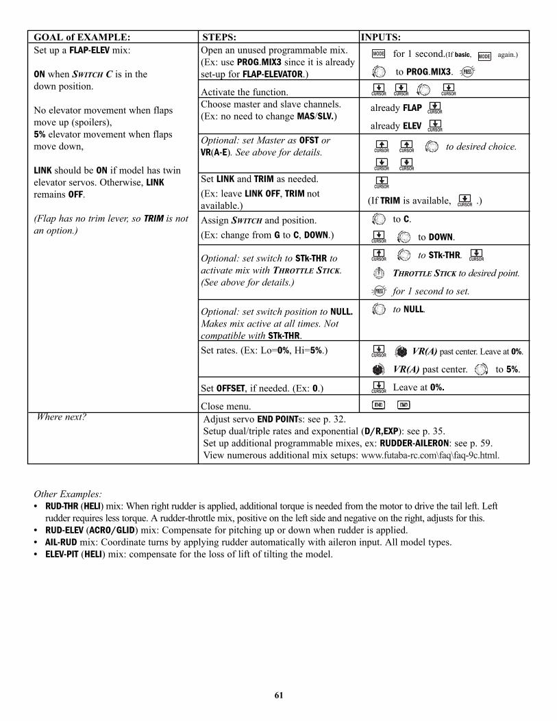
GOAL of EXAMPLE: STEPS: INPUTS:
Other Examples:• RUD-THR (HELI) mix: When right rudder is applied, additional torque is needed from the motor to drive the tail left. Left
rudder requires less torque. A rudder-throttle mix, positive on the left side and negative on the right, adjusts for this.• RUD-ELEV (ACRO/GLID) mix: Compensate for pitching up or down when rudder is applied.• AIL-RUD mix: Coordinate turns by applying rudder automatically with aileron input. All model types.• ELEV-PIT (HELI) mix: compensate for the loss of lift of tilting the model.
61
Set up a FLAP-ELEV mix:
ON when SWITCH C is in thedown position.
No elevator movement when flapsmove up (spoilers), 5% elevator movement when flapsmove down,
LINK should be ON if model has twinelevator servos. Otherwise, LINKremains OFF.
(Flap has no trim lever, so TRIM is notan option.)
Where next?
Open an unused programmable mix.(Ex: use PROG.MIX3 since it is alreadyset-up for FLAP-ELEVATOR.)
Activate the function.Choose master and slave channels.(Ex: no need to change MAS/SLV.)
Optional: set Master as OFST or VR(A-E). See above for details.
Set LINK and TRIM as needed.(Ex: leave LINK OFF, TRIM notavailable.)Assign SWITCH and position.(Ex: change from G to C, DOWN.)
Optional: set switch to STk-THR toactivate mix with THROTTLE STICK.(See above for details.)
Optional: set switch position to NULL.Makes mix active at all times. Notcompatible with STk-THR.Set rates. (Ex: Lo=0%, Hi=5%.)
Set OFFSET, if needed. (Ex: 0.)
Close menu.
for 1 second.(If basic, again.)
to PROG.MIX3.
already FLAP
already ELEV
to desired choice.
(If TRIM is available, .)
to C.
to DOWN.
to STk-THR.
THROTTLE STICK to desired point.
for 1 second to set.
to NULL.
VR(A) past center. Leave at 0%.
VR(A) past center. to 5%.
Leave at 0%.
Adjust servo END POINTs: see p. 32.Setup dual/triple rates and exponential (D/R,EXP): see p. 35.Set up additional programmable mixes, ex: RUDDER-AILERON: see p. 59.View numerous additional mix setups: www.futaba-rc.com\faq\faq-9c.html.
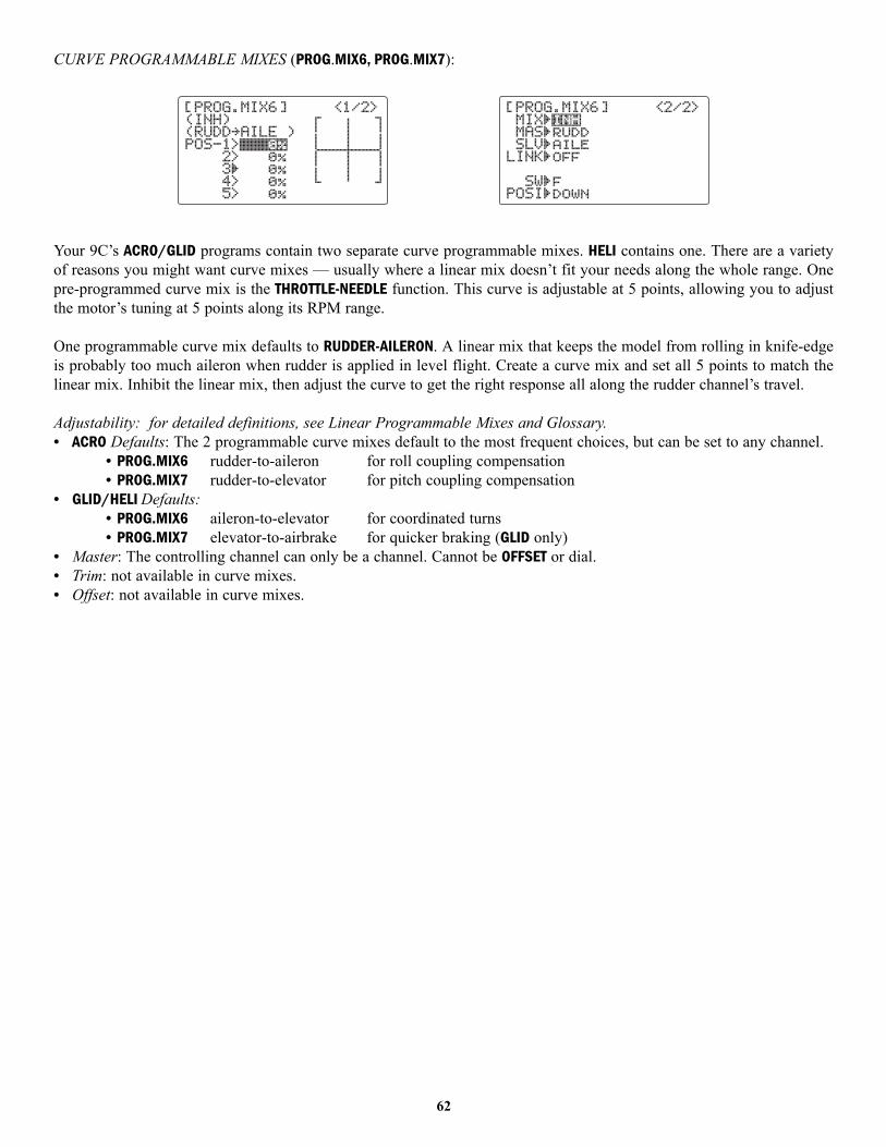
CURVE PROGRAMMABLE MIXES (PROG.MIX6, PROG.MIX7):
Your 9C’s ACRO/GLID programs contain two separate curve programmable mixes. HELI contains one. There are a varietyof reasons you might want curve mixes — usually where a linear mix doesn’t fit your needs along the whole range. Onepre-programmed curve mix is the THROTTLE-NEEDLE function. This curve is adjustable at 5 points, allowing you to adjustthe motor’s tuning at 5 points along its RPM range.
One programmable curve mix defaults to RUDDER-AILERON. A linear mix that keeps the model from rolling in knife-edgeis probably too much aileron when rudder is applied in level flight. Create a curve mix and set all 5 points to match thelinear mix. Inhibit the linear mix, then adjust the curve to get the right response all along the rudder channel’s travel.
Adjustability: for detailed definitions, see Linear Programmable Mixes and Glossary.• ACRO Defaults: The 2 programmable curve mixes default to the most frequent choices, but can be set to any channel.
• PROG.MIX6 rudder-to-aileron for roll coupling compensation• PROG.MIX7 rudder-to-elevator for pitch coupling compensation
• GLID/HELI Defaults: • PROG.MIX6 aileron-to-elevator for coordinated turns• PROG.MIX7 elevator-to-airbrake for quicker braking (GLID only)
• Master: The controlling channel can only be a channel. Cannot be OFFSET or dial.• Trim: not available in curve mixes.• Offset: not available in curve mixes.
62
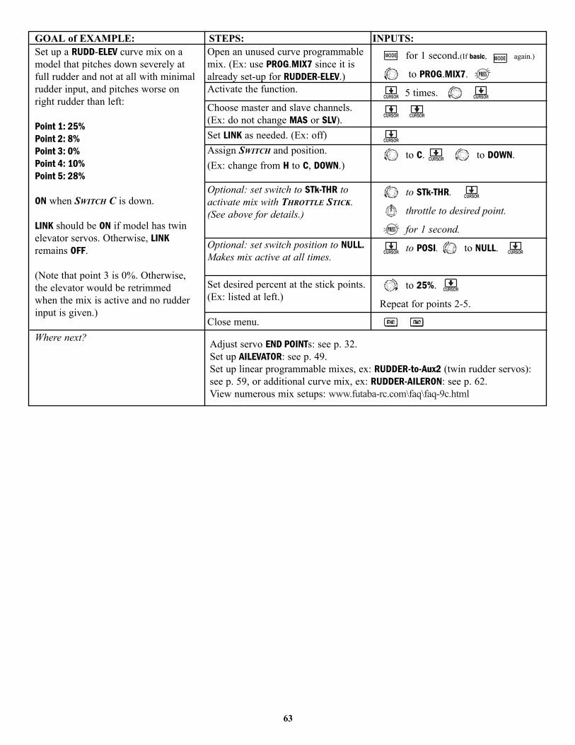
GOAL of EXAMPLE: STEPS: INPUTS:
63
Set up a RUDD-ELEV curve mix on amodel that pitches down severely atfull rudder and not at all with minimalrudder input, and pitches worse onright rudder than left:
Point 1: 25%Point 2: 8%Point 3: 0%Point 4: 10%Point 5: 28%
ON when SWITCH C is down.
LINK should be ON if model has twinelevator servos. Otherwise, LINKremains OFF.
(Note that point 3 is 0%. Otherwise,the elevator would be retrimmedwhen the mix is active and no rudderinput is given.)
Where next?
Open an unused curve programmablemix. (Ex: use PROG.MIX7 since it isalready set-up for RUDDER-ELEV.)Activate the function.
Choose master and slave channels.(Ex: do not change MAS or SLV).Set LINK as needed. (Ex: off)Assign SWITCH and position.(Ex: change from H to C, DOWN.)
Optional: set switch to STk-THR toactivate mix with THROTTLE STICK.(See above for details.)
Optional: set switch position to NULL.Makes mix active at all times.
Set desired percent at the stick points.(Ex: listed at left.)
Close menu.
for 1 second.(If basic, again.)
to PROG.MIX7.
5 times.
to C. to DOWN.
to STk-THR.
throttle to desired point.
for 1 second.
to POSI. to NULL.
to 25%.
Repeat for points 2-5.
Adjust servo END POINTs: see p. 32.Set up AILEVATOR: see p. 49.Set up linear programmable mixes, ex: RUDDER-to-Aux2 (twin rudder servos):see p. 59, or additional curve mix, ex: RUDDER-AILERON: see p. 62.View numerous mix setups: www.futaba-rc.com\faq\faq-9c.html
Special Additions, Functions, And Added Equipment Commonly Used On Powered Aircraft
Gyros: Just as torque rotates an aircraft on the runway during take-off, helicopters struggle with torque twisting the modelevery time throttle is applied. For many years gyroscopes have been used on model helicopters to control this. Incompetition aerobatics and scale aircraft competition alike, the usefulness of gyros has recently come to light. For in-depthinformation on gyro types, please see p. 89.
For aerobatics, gyros on rudder and elevator fix over-rotation of snaps and spins as well as tail wagging in stall turns. (Futabaoffers a twin-axis gyro, GYA-352, that controls two axes with a single gyro.) For 3D aerobatics (below stall speed, such as torquerolls), heading-hold/AVCS gyros on rudder and elevator dramatically simplify these maneuvers. For scale models, gyros arefrequently used to simplify take-offs and landings by keeping the model straight during throttle application.
Always be careful if using a heading-hold/AVCS gyro, as it will correct any change in yaw that is not caused bymovement of the rudder (like making a turn with just aileron and elevator). Typically, modelers use heading-hold/AVCS settings only for specific maneuvers, such as take-offs and torque rolls, then switch to normal mode orOFF for the remainder of the flight to avoid this risk.
While the 9C’s ACRO/GLID programming does not offer gyro-specific programming, simply adjusting the END POINTs ofthe channel that is used to control the gyro’s gain will adjust the gyro’s performance in flight. For details on gain and othergyro functions, please see the HELI GYRO programming, p. 89.
Retracts: Retractable landing gear is often used on scale models for increased realism and on high performance models todecrease drag. The gear servo is typically plugged into CH5, which defaults to a 2-position switch for simplicity.
Mechanical retracts require the use of a specialized non-proportional retract servo. Retract servos go from fulltravel one direction to full travel the other direction, then mechanically hold the gear into the locked position. Aregular servo used for mechanical retracts will continue to draw full power the entire time, prematurely drainingthe battery and risking crash of your model. End point will not adjust a retract servo.
Pneumatic (air driven) retracts use a standard servo to control an air valve which directs air into or out of the retract units,moving the gear up or down. Pneumatics are easier to install but require added maintenance of the air system.
Gear Doors: Some scale models with retracts also have separate gear doors to cover the scale gear. For one example ofhow to operate the gear doors separately from the retracts, please visit our website: www.futaba-rc.com\faq\faq-9c.html.
Smoke Systems: Many scale and aerobatic models use smoke systems to provide increased realism or a more impressivedemonstration. There are many smoke systems available, with varying types of control. Most use a servo to increase/decrease theflow of smoke fluid into the specialized smoke muffler. The oil is heated in the muffler, creating smoke.
It is a good practice to set up a “safety” that shuts off the smoke oil if the throttle is lowered below half-stick. For a detailedexample of a smoke system setup, please visit our website: www.futaba-rc.com\faq\faq-9c.html.
Kill Switches: For safety reasons, it is strongly recommended that an electronic kill switch be installed in all gasoline-powered aircraft. In case of any type of in-flight problem (such as prop failure, exhaust vibrating off, throttle servo failure,radio interference), the modeler can shut the engine off quickly and safely in flight. Additionally, FailSafe (F/S) settingsare recommended to shut the engine off in case of sufficient interference to trigger the PCM FailSafe settings.
Lastly, an electronic kill switch set to “off” prior to the aircraft’s power being shut off adds an additional safety shouldsomeone accidentally turn on the mechanical kill switch on the exterior of the model.
Bomb Drops, Paratroopers, and other Released Items: Many sport and scale models include one or more of these funadd-ons. Typically, all are controlled by a simple micro-switch plugged into CH9. The switch is assigned in AUX-CH.
64
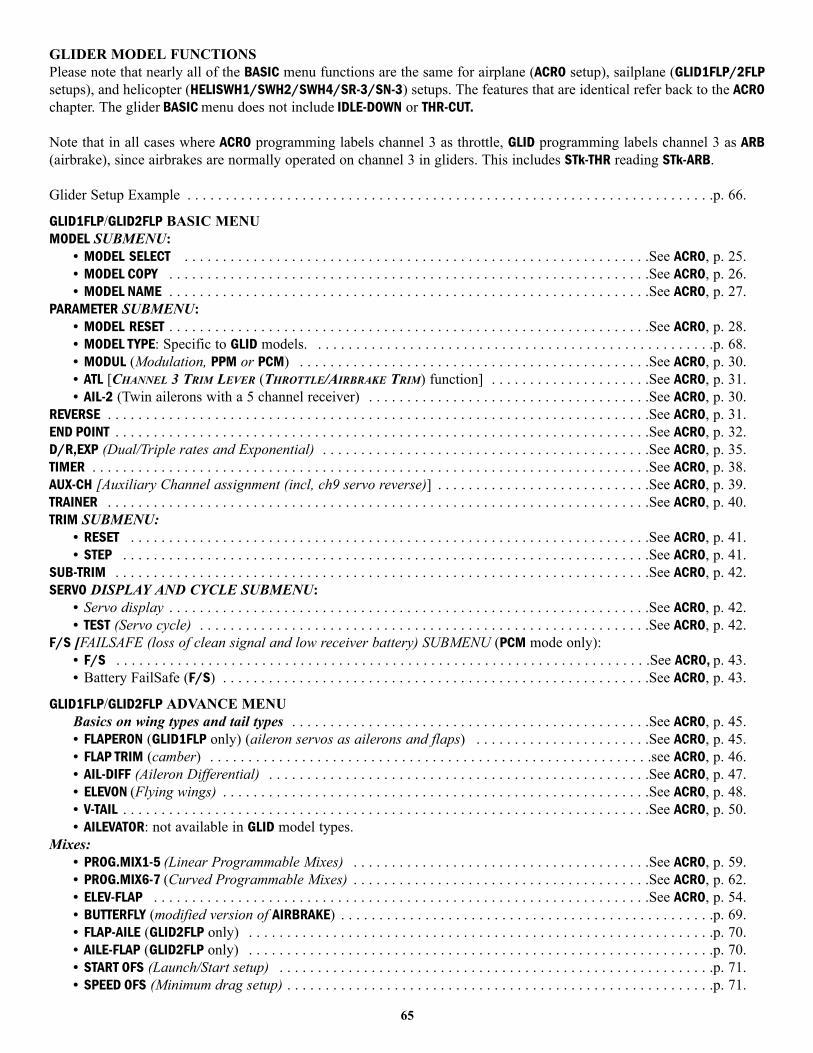
GLIDER MODEL FUNCTIONS Please note that nearly all of the BASIC menu functions are the same for airplane (ACRO setup), sailplane (GLID1FLP/2FLPsetups), and helicopter (HELISWH1/SWH2/SWH4/SR-3/SN-3) setups. The features that are identical refer back to the ACROchapter. The glider BASIC menu does not include IDLE-DOWN or THR-CUT.
Note that in all cases where ACRO programming labels channel 3 as throttle, GLID programming labels channel 3 as ARB(airbrake), since airbrakes are normally operated on channel 3 in gliders. This includes STk-THR reading STk-ARB.
Glider Setup Example . . . . . . . . . . . . . . . . . . . . . . . . . . . . . . . . . . . . . . . . . . . . . . . . . . . . . . . . . . . . . . . . . . . . .p. 66.
GLID1FLP/GLID2FLP BASIC MENUMODEL SUBMENU:
• MODEL SELECT . . . . . . . . . . . . . . . . . . . . . . . . . . . . . . . . . . . . . . . . . . . . . . . . . . . . . . . . . . . . .See ACRO, p. 25.• MODEL COPY . . . . . . . . . . . . . . . . . . . . . . . . . . . . . . . . . . . . . . . . . . . . . . . . . . . . . . . . . . . . . . .See ACRO, p. 26.• MODEL NAME . . . . . . . . . . . . . . . . . . . . . . . . . . . . . . . . . . . . . . . . . . . . . . . . . . . . . . . . . . . . . . .See ACRO, p. 27.
PARAMETER SUBMENU:• MODEL RESET . . . . . . . . . . . . . . . . . . . . . . . . . . . . . . . . . . . . . . . . . . . . . . . . . . . . . . . . . . . . . . .See ACRO, p. 28.• MODEL TYPE: Specific to GLID models. . . . . . . . . . . . . . . . . . . . . . . . . . . . . . . . . . . . . . . . . . . . . . . . . . . . .p. 68.• MODUL (Modulation, PPM or PCM) . . . . . . . . . . . . . . . . . . . . . . . . . . . . . . . . . . . . . . . . . . . . . .See ACRO, p. 30.• ATL [CHANNEL 3 TRIM LEVER (THROTTLE/AIRBRAKE TRIM) function] . . . . . . . . . . . . . . . . . . . . .See ACRO, p. 31.• AIL-2 (Twin ailerons with a 5 channel receiver) . . . . . . . . . . . . . . . . . . . . . . . . . . . . . . . . . . . . .See ACRO, p. 30.
REVERSE . . . . . . . . . . . . . . . . . . . . . . . . . . . . . . . . . . . . . . . . . . . . . . . . . . . . . . . . . . . . . . . . . . . . . . .See ACRO, p. 31.END POINT . . . . . . . . . . . . . . . . . . . . . . . . . . . . . . . . . . . . . . . . . . . . . . . . . . . . . . . . . . . . . . . . . . . . . .See ACRO, p. 32.D/R,EXP (Dual/Triple rates and Exponential) . . . . . . . . . . . . . . . . . . . . . . . . . . . . . . . . . . . . . . . . . . .See ACRO, p. 35.TIMER . . . . . . . . . . . . . . . . . . . . . . . . . . . . . . . . . . . . . . . . . . . . . . . . . . . . . . . . . . . . . . . . . . . . . . . . .See ACRO, p. 38.AUX-CH [Auxiliary Channel assignment (incl, ch9 servo reverse)] . . . . . . . . . . . . . . . . . . . . . . . . . . . .See ACRO, p. 39.TRAINER . . . . . . . . . . . . . . . . . . . . . . . . . . . . . . . . . . . . . . . . . . . . . . . . . . . . . . . . . . . . . . . . . . . . . . .See ACRO, p. 40.TRIM SUBMENU:
• RESET . . . . . . . . . . . . . . . . . . . . . . . . . . . . . . . . . . . . . . . . . . . . . . . . . . . . . . . . . . . . . . . . . . . .See ACRO, p. 41.• STEP . . . . . . . . . . . . . . . . . . . . . . . . . . . . . . . . . . . . . . . . . . . . . . . . . . . . . . . . . . . . . . . . . . . . .See ACRO, p. 41.
SUB-TRIM . . . . . . . . . . . . . . . . . . . . . . . . . . . . . . . . . . . . . . . . . . . . . . . . . . . . . . . . . . . . . . . . . . . . . .See ACRO, p. 42.SERVO DISPLAY AND CYCLE SUBMENU:
• Servo display . . . . . . . . . . . . . . . . . . . . . . . . . . . . . . . . . . . . . . . . . . . . . . . . . . . . . . . . . . . . . . .See ACRO, p. 42.• TEST (Servo cycle) . . . . . . . . . . . . . . . . . . . . . . . . . . . . . . . . . . . . . . . . . . . . . . . . . . . . . . . . . . .See ACRO, p. 42.
F/S [FAILSAFE (loss of clean signal and low receiver battery) SUBMENU (PCM mode only):• F/S . . . . . . . . . . . . . . . . . . . . . . . . . . . . . . . . . . . . . . . . . . . . . . . . . . . . . . . . . . . . . . . . . . . . . .See ACRO, p. 43.• Battery FailSafe (F/S) . . . . . . . . . . . . . . . . . . . . . . . . . . . . . . . . . . . . . . . . . . . . . . . . . . . . . . . .See ACRO, p. 43.
GLID1FLP/GLID2FLP ADVANCE MENUBasics on wing types and tail types . . . . . . . . . . . . . . . . . . . . . . . . . . . . . . . . . . . . . . . . . . . . . . .See ACRO, p. 45.• FLAPERON (GLID1FLP only) (aileron servos as ailerons and flaps) . . . . . . . . . . . . . . . . . . . . . . .See ACRO, p. 45.• FLAP TRIM (camber) . . . . . . . . . . . . . . . . . . . . . . . . . . . . . . . . . . . . . . . . . . . . . . . . . . . . . . . . . .see ACRO, p. 46.• AIL-DIFF (Aileron Differential) . . . . . . . . . . . . . . . . . . . . . . . . . . . . . . . . . . . . . . . . . . . . . . . . . .See ACRO, p. 47.• ELEVON (Flying wings) . . . . . . . . . . . . . . . . . . . . . . . . . . . . . . . . . . . . . . . . . . . . . . . . . . . . . . . .See ACRO, p. 48.• V-TAIL . . . . . . . . . . . . . . . . . . . . . . . . . . . . . . . . . . . . . . . . . . . . . . . . . . . . . . . . . . . . . . . . . . . . .See ACRO, p. 50.• AILEVATOR: not available in GLID model types.
Mixes:• PROG.MIX1-5 (Linear Programmable Mixes) . . . . . . . . . . . . . . . . . . . . . . . . . . . . . . . . . . . . . . .See ACRO, p. 59.• PROG.MIX6-7 (Curved Programmable Mixes) . . . . . . . . . . . . . . . . . . . . . . . . . . . . . . . . . . . . . . .See ACRO, p. 62.• ELEV-FLAP . . . . . . . . . . . . . . . . . . . . . . . . . . . . . . . . . . . . . . . . . . . . . . . . . . . . . . . . . . . . . . . . .See ACRO, p. 54.• BUTTERFLY (modified version of AIRBRAKE) . . . . . . . . . . . . . . . . . . . . . . . . . . . . . . . . . . . . . . . . . . . . . . . . .p. 69.• FLAP-AILE (GLID2FLP only) . . . . . . . . . . . . . . . . . . . . . . . . . . . . . . . . . . . . . . . . . . . . . . . . . . . . . . . . . . . . .p. 70.• AILE-FLAP (GLID2FLP only) . . . . . . . . . . . . . . . . . . . . . . . . . . . . . . . . . . . . . . . . . . . . . . . . . . . . . . . . . . . . .p. 70.• START OFS (Launch/Start setup) . . . . . . . . . . . . . . . . . . . . . . . . . . . . . . . . . . . . . . . . . . . . . . . . . . . . . . . . .p. 71.• SPEED OFS (Minimum drag setup) . . . . . . . . . . . . . . . . . . . . . . . . . . . . . . . . . . . . . . . . . . . . . . . . . . . . . . . .p. 71.
65

GETTING STARTED WITH A BASIC 4-CHANNEL (Aileron/Flap/Rudder/Elevator) GLIDERThis guideline is intended to help you get acquainted with the radio, to give you a jump start on using your new radio, andto give you some ideas and direction in how to do even more with this powerful system than you may have alreadyconsidered. It follows our basic format of all programming pages: a big picture overview of what we’re trying toaccomplish; a “by name” description of the steps to help acquaint you with the radio; and a step-by-step instruction to leaveout the mystery and challenge of setting up your model.
For additional details on utilizing each function, see that function’s section in this manual – the page numbers are indicatedin the first column as a convenience to you.
GOAL of EXAMPLE: STEPS: INPUTS:
66
Prepare your aircraft. Install all servos, switches, receiver per your model’s instructions.Turn on transmitter then receiver; adjust all linkages so surfaces are nearly centered.Mechanically adjust all linkages to get as close as possible to proper controlthrows and minimize binding prior to radio set up.Check servo direction and throws.Make notes now of what you will need to change during programming.
Select the proper MODEL TYPE for yourmodel. (Ex: GLID1FLP.) See p. 68.
[NOTE: This is one of several functionsthat requires confirmation to make achange. Only critical changes such as aMODEL RESET require additionalkeystrokes to accept the change.]
NAME the model.P. 25.
(Note that you do not need to doanything to “save” or store this data.)
REVERSE servos as needed for propercontrol operation.P. 31.
In the BASIC menu, open thePARAMETER submenu.
Go to MODEL TYPE.Select proper MODEL TYPE. Ex:GLID1FLP. Confirm the change.
Close the PARAMETER submenu.
In the BASIC menu, open the MODELsubmenu.
Go to MODEL NAME.
Input aircraft’s name.
Close the MODEL submenu when done.In the BASIC menu, open (servo)REVERSE.
Choose desired servo and reverse its direction of travel. (Ex: reverserudder servo.)
Turn on the transmitter.for 1 second.(If ADVANCE, again.)
then to highlight PARAMETER.
to choose PARAMETER.
to MODEL TYPE.
to GLID(1FLP).
for 1 second.
Sure? Displays. to confirm.
to return to BASIC menu.
as needed to highlight MODEL.
to choose MODEL.
(1st character of model’s name ishighlighted.)
to change first character.
When proper character is displayed,
to move to next character and repeat.
to return to BASIC menu.
4 steps to REVERSE.
to choose REVERSE.
to CH4: RUDD.
so REV is highlighted.
Repeat as needed.
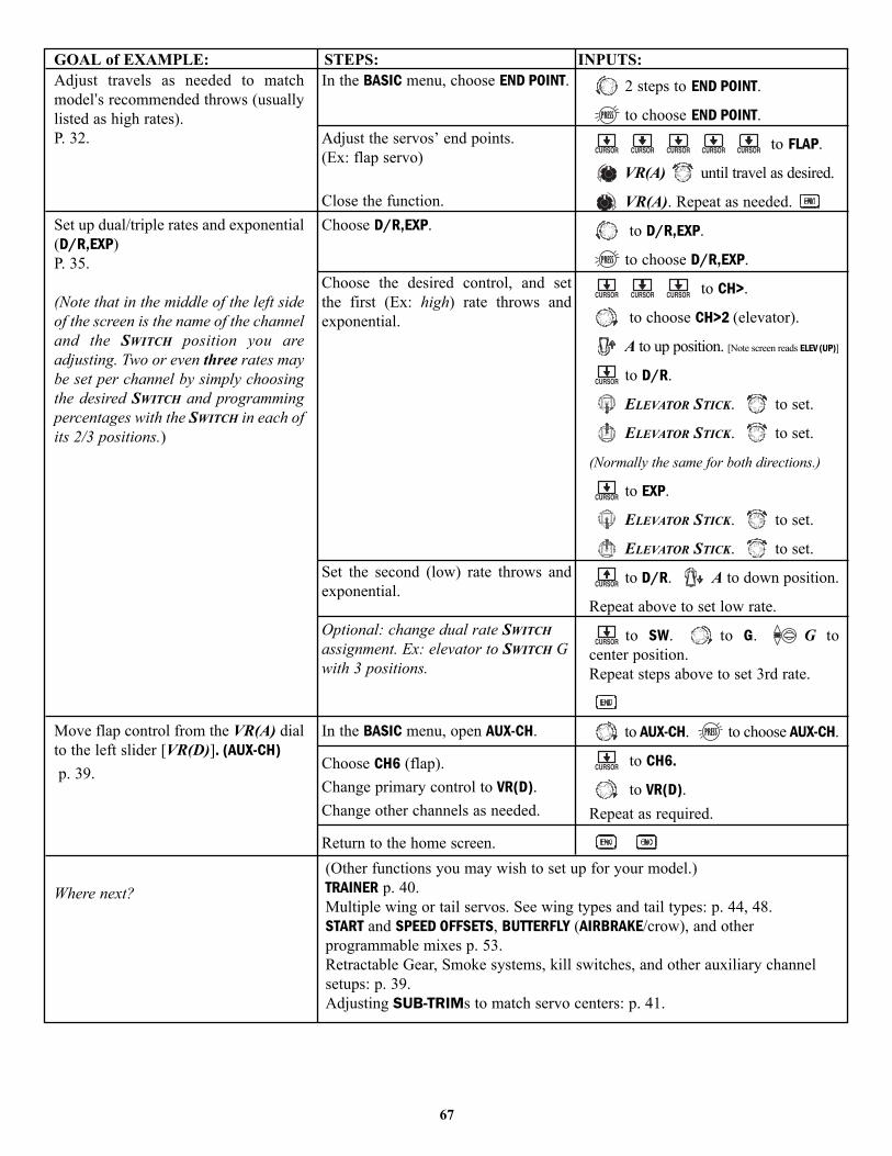
GOAL of EXAMPLE: STEPS: INPUTS:
67
Adjust travels as needed to matchmodel’s recommended throws (usuallylisted as high rates).P. 32.
Set up dual/triple rates and exponential(D/R,EXP)P. 35.
(Note that in the middle of the left sideof the screen is the name of the channeland the SWITCH position you areadjusting. Two or even three rates maybe set per channel by simply choosingthe desired SWITCH and programmingpercentages with the SWITCH in each ofits 2/3 positions.)
Move flap control from the VR(A) dialto the left slider [VR(D)]. (AUX-CH)p. 39.
Where next?
In the BASIC menu, choose END POINT.
Adjust the servos’ end points.(Ex: flap servo)
Close the function.Choose D/R,EXP.
Choose the desired control, and set the first (Ex: high) rate throws andexponential.
Set the second (low) rate throws andexponential.
Optional: change dual rate SWITCHassignment. Ex: elevator to SWITCH Gwith 3 positions.
In the BASIC menu, open AUX-CH.
Choose CH6 (flap).Change primary control to VR(D).Change other channels as needed.
Return to the home screen.
2 steps to END POINT.
to choose END POINT.
to FLAP.
VR(A) until travel as desired.
VR(A). Repeat as needed.
to D/R,EXP.
to choose D/R,EXP.
to CH>.
to choose CH>2 (elevator).
A to up position. [Note screen reads ELEV (UP)]
to D/R.
ELEVATOR STICK. to set.
ELEVATOR STICK. to set.
(Normally the same for both directions.)
to EXP.
ELEVATOR STICK. to set.
ELEVATOR STICK. to set.
to D/R. A to down position.
Repeat above to set low rate.
to SW. to G. G tocenter position.Repeat steps above to set 3rd rate.
to AUX-CH. to choose AUX-CH.
to CH6.
to VR(D).Repeat as required.
(Other functions you may wish to set up for your model.)TRAINER p. 40.Multiple wing or tail servos. See wing types and tail types: p. 44, 48.START and SPEED OFFSETS, BUTTERFLY (AIRBRAKE/crow), and otherprogrammable mixes p. 53.Retractable Gear, Smoke systems, kill switches, and other auxiliary channelsetups: p. 39.Adjusting SUB-TRIMs to match servo centers: p. 41.
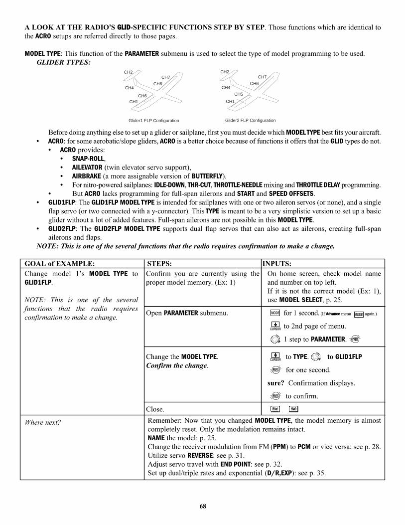
A LOOK AT THE RADIO’S GGLLIIDD-SPECIFIC FUNCTIONS STEP BY STEP. Those functions which are identical tothe ACRO setups are referred directly to those pages.
MODEL TYPE: This function of the PARAMETER submenu is used to select the type of model programming to be used.GLIDER TYPES:
Before doing anything else to set up a glider or sailplane, first you must decide which MODEL TYPE best fits your aircraft.• ACRO: for some aerobatic/slope gliders, ACRO is a better choice because of functions it offers that the GLID types do not.
• ACRO provides:• SNAP-ROLL,• AILEVATOR (twin elevator servo support),• AIRBRAKE (a more assignable version of BUTTERFLY). • For nitro-powered sailplanes: IDLE-DOWN, THR-CUT, THROTTLE-NEEDLE mixing and THROTTLE DELAY programming.
• But ACRO lacks programming for full-span ailerons and START and SPEED OFFSETS.• GLID1FLP: The GLID1FLP MODEL TYPE is intended for sailplanes with one or two aileron servos (or none), and a single
flap servo (or two connected with a y-connector). This TYPE is meant to be a very simplistic version to set up a basicglider without a lot of added features. Full-span ailerons are not possible in this MODEL TYPE.
• GLID2FLP: The GLID2FLP MODEL TYPE supports dual flap servos that can also act as ailerons, creating full-spanailerons and flaps.
NOTE: This is one of the several functions that the radio requires confirmation to make a change.
GOAL of EXAMPLE: STEPS: INPUTS:
CH1
CH2
CH4
CH5
CH6
CH7
Glider2 FLP Configuration
CH1
CH2
CH4
CH6
CH6
CH7
Glider1 FLP Configuration
68
Change model 1’s MODEL TYPE toGLID1FLP.
NOTE: This is one of the severalfunctions that the radio requiresconfirmation to make a change.
Where next?
Confirm you are currently using theproper model memory. (Ex: 1)
Open PARAMETER submenu.
Change the MODEL TYPE.Confirm the change.
Close.
On home screen, check model nameand number on top left.If it is not the correct model (Ex: 1),use MODEL SELECT, p. 25.
for 1 second. (If Advance menu again.)
to 2nd page of menu.
1 step to PARAMETER.
to TYPE. to GLID1FLP
for one second.
sure? Confirmation displays.
to confirm.
Remember: Now that you changed MODEL TYPE, the model memory is almostcompletely reset. Only the modulation remains intact.NAME the model: p. 25.Change the receiver modulation from FM (PPM) to PCM or vice versa: see p. 28.Utilize servo REVERSE: see p. 31.Adjust servo travel with END POINT: see p. 32.Set up dual/triple rates and exponential (D/R,EXP): see p. 35.
GLIDER ADVANCE MENU
Varied wing types and tail types (twin aileron servos, twin elevator servos, elevon, v-tail, etc). See p. 44-50 for basic information.• FLAPERON (GLID1FLP only): 2 aileron servos operate in opposite directions as ailerons and same direction as flaps. See p. 45.• FLAP TRIM: provides camber movement or trimming of flaperons as flaps. See p. 46.
• For sailplanes, this function is also used as wing camber. The amount depends on the model, but usually asmall amount (less than 10%) is preferred, since too much camber produces excess drag. Don’t use more thanabout 1/16” travel up or down for glider camber. Some airfoils, such as the RG-15, should be flown with NOreflex/camber. Be sure to consult your model’s manual for guidelines.
• Note that even though you may make FLAP-TRIM active while using AIL-DIFF, it will not have any effect. TheONLY function that allows control of the ailerons as flaps in the AIL-DIFF configuration is airbrake.)
• Aileron Differential (AIL-DIFF): allows twin aileron servos to provide differential down travel from up travel. See p. 47.• Using a 5-channel receiver with FLAPERON and AIL-DIFF. See AIL-2, p. 47.• ELEVON: for flying wings. See p. 48.• V-TAIL: for models with 2 servos operating together to create roll and pitch control. See p. 50.• AILEVATOR: not available in GLID model types.
Mixes:• Linear Programmable mixes (PROG.MIX1-5): fully assignable programmable mixes with a linear response. see p. 59.• Curved Programmable mixes (PROG.MIX6-7): fully assignable programmable mixes with a curved response. See p. 62.• ELEV-FLAP: pre-programmed mix creates elevator movement from the inboard flaps as well as elevators. See p. 54.• BUTTERFLY: Often called crow, BUTTERFLY is the glider version of AIRBRAKE. (BUTTERFLY does not have the option
to activate it solely from a switch, and its activation switch is not assignable. BUTTERFLY may only be turned on/offby SWITCH A, and always provides progressively more BUTTERFLY as the CHANNEL 3 (THROTTLE) STICK is lowered,or raised if used THR-REV, p. 31.) See AIRBRAKE, p. 55.
Full Span Mixing: Flap-to-Aileron and Aileron-to-Flap
• FLAP-AILE (GLID2FLP only): This pre-programmed mix is used to create full span flap action on a glider with 4 wing servos.This changes the camber over the entire wing, which produces less drag than just dropping the flaps by themselves. SinceFLAP-AILE and AILE-FLAP are generally utilized together, one example is shown below setting up both. NOTE: When youhave ELEV-FLAP mixing also, the trailing edge droops with the elevators, increasing pitch response.
Adjustability:• RATE range of -100 to +100. Negative setting would result in up flaperon with down flap and vice versa.• OFFSET range of –30 to +30. Setting offset position sets the flap position at which the flaperons are neutral. Intended
for models that do not have the flaps positioned neutral at the flap servo’s center. (ie. down travel only)• SWITCH A-H fully assignable.• POSITION fully assignable, including NULL (mix always on) and Up&Cntr and Cntr&Dn to activate the mix in 2
separate positions of the same SWITCH. (This allows easy setup of one SWITCH position which is no FLAP-AILEor AILE-FLAP mixing, one with both FLAP-AILE and AILE-FLAP mixing, and one with just FLAP-AILE mixing.)
69

• AILE-FLAP (GLID2FLP only): This pre-programmed mix is used to create full span aileron action on a glider with 4wing servos. This increases the roll rate and decreases induced drag. For normal flying, a value of about 50% isoften used. For slope racing or F3B models in speed runs, you may wish to use a larger value approaching 100%.
Adjustability:• RATE range of -100 to +100. Negative setting would result in opposite aileron action from flaps. • SWITCH A-H fully assignable.• POSITION fully assignable, including NULL (mix always on) and Up&Cntr and Cntr&Dn to activate the mix in 2
separate positions of the same SWITCH. (This allows easy setup of one SWITCH position which is no FLAP-AILEor AILE-FLAP mixing, one with both FLAP-AILE and AILE-FLAP mixing, and one with just FLAP-AILE mixing.)
GOAL of EXAMPLE: STEPS: INPUTS:
REAR VIEW OF MODEL WITH LEFT AILERON COMMANDREAR VIEW OF MODEL WITH LEFT AILERON COMMAND
70
Turn on FLAP-AILE mixing. Set RATE to48%, which is the portion of the totalaileron travel that matches the maximumflap travel.
Ex: Set up SWITCH C as follows:UP = no full span mixing.CTR = flap-ail and ail-flapDWN = flap-ail mixing only.
Assign to SWITCH C center and down.
Turn on AILE-FLAP mixing. Set rate to100% for maximum possible flaptravel with ailerons.
Assign to SWITCH C center.
Where next?
Open FLAP-AILE mixing function.
Activate the function.
Set the rate. (Ex: 48%)
Optional: adjust the flap position atwhich the flaperons are zeroed.
Assign the SWITCH and position.(Ex: C Cntr&Dn)
Close the function.
Open AILE-FLAP submenu.
Activate the function.
Set the rate. (Ex: 100% each way)
Assign the SWITCH and position.
Close.
for 1 second. (If BASIC menu , again.)
to 2nd page of menu.
to FLAP-AILE.
to ON.
to +48%.
or VR(A) as needed.
for 1 second to set.
to SW. to C.
to Cntr&Dn.
to AILE-FLAP.
to ON.
AILERON STICK. to +100%.
AILERON STICK. to +100%.
to SW. to C.
to CENTER.
ELEV-FLAP mixing. See p. 54.BUTTERFLY. See p. 55.Use a mix to OFFSET the flaps a set distance on a specified switch: see p. 59.View additional model setups on the internet: www.futaba-rc.com\faq\faq-9c.html

• Launch (Start) Offset (START OFS): The Start function is used to offset the aileron, elevator, and flap servos to theposition that provides maximum lift during launch. Normally the ailerons and flaps are drooped about 20-30, withthe flaps drooped slightly more to prevent tip-stalling on tow. The elevator can also be offset in order to trim outany pitch changes caused by the flap and aileron presets.
Adjustability:• This function is only activated by flipping SWITCH G to the back position. If you wish to have this three-
position switch above the left-hand stick (position E), you should purchase a 9CH transmitter.• Separate adjustments for each aileron and flap servo (two flap settings for GLID2FLP) and for elevator.• RANGE for each adjustment is –100 to +100.• Optional assignable dial (VR) to adjust all 4 wing servos in unison, 1% at a time, across all 4 servos in flight.
GOAL of EXAMPLE: STEPS: INPUTS:
71
Set up a START OFS to gain maximumpossible lift on launch.Each Aileron: 50%.Each Flap: 100%.Elevator: -5% to compensate.
Note: switch is not assignable. Must beSWITCH (9CA=G, 9CH=E.)
Where next?
Open START OFS function.
Activate the function.
Set the rates. (Ex: AIL1 and 2, 50%,FLAP1 and 2, 100%, ELEV –5%.)
Optional: set a knob to adjust travelof all 4 wing servos in flight.Close the function.
for 1 second. (If BASIC menu , again.)
to 2nd page. to START OFS.
Flip switch G toward you.
to OFF. to AIL1..to +50%. to AIL2.
to +50%. to ELEV.
Repeat for ELEV, FLP1 and 2, AIL2.
to desired knob.
SPEED OFS mixing. See p. 72.BUTTERFLY. See p. 55.Create a programmable mix to meet your model’s setups: see p. 59.View additional model setups on the internet: www.futaba-rc.com\faq\faq-9c.html.
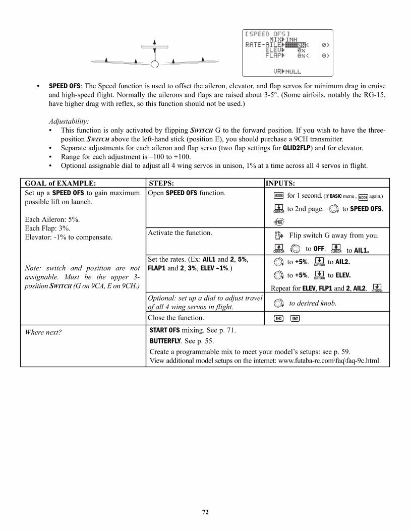
• SPEED OFS: The Speed function is used to offset the aileron, elevator, and flap servos for minimum drag in cruiseand high-speed flight. Normally the ailerons and flaps are raised about 3-5°. (Some airfoils, notably the RG-15,have higher drag with reflex, so this function should not be used.)
Adjustability:• This function is only activated by flipping SWITCH G to the forward position. If you wish to have the three-
position SWITCH above the left-hand stick (position E), you should purchase a 9CH transmitter.• Separate adjustments for each aileron and flap servo (two flap settings for GLID2FLP) and for elevator.• Range for each adjustment is –100 to +100.• Optional assignable dial to adjust all 4 wing servos in unison, 1% at a time across all 4 servos in flight.
GOAL of EXAMPLE: STEPS: INPUTS:
72
Set up a SPEED OFS to gain maximumpossible lift on launch.
Each Aileron: 5%.Each Flap: 3%.Elevator: -1% to compensate.
Note: switch and position are notassignable. Must be the upper 3-position SWITCH (G on 9CA, E on 9CH.)
Where next?
Open SPEED OFS function.
Activate the function.
Set the rates. (Ex: AIL1 and 2, 5%,FLAP1 and 2, 3%, ELEV –1%.)
Optional: set up a dial to adjust travelof all 4 wing servos in flight.Close the function.
for 1 second. (If BASIC menu , again.)
to 2nd page. to SPEED OFS.
Flip switch G away from you.
to OFF. to AIL1..to +5%. to AIL2.
to +5%. to ELEV.
Repeat for ELEV, FLP1 and 2, AIL2.
to desired knob.
START OFS mixing. See p. 71.BUTTERFLY. See p. 55.Create a programmable mix to meet your model’s setups: see p. 59.View additional model setups on the internet: www.futaba-rc.com\faq\faq-9c.html.

HELICOPTER MODEL FUNCTIONS
Please note that nearly all of the BASIC menu functions are the same for airplane (ACRO setup), sailplane (GLID1FLP/2FLPsetups), and helicopter (HELISWH1/SWH2/SWH4/SR-3/SN-3) setups. The features that are identical refer back to the ACROchapter. The Helicopter BASIC menu includes the normal condition’s throttle and collective pitch curves and revo. mixing.(idle-ups and throttle hold are advanced features and are in the ADVANCE menu).
Helicopter Setup Example . . . . . . . . . . . . . . . . . . . . . . . . . . . . . . . . . . . . . . . . . . . . . . . . . . . . . . . . . . . . . . . . .p. 74.HELI (SWH1/2/4, SN-3, SR-3) BASIC MENUMODEL SUBMENU:
• MODEL SELECT . . . . . . . . . . . . . . . . . . . . . . . . . . . . . . . . . . . . . . . . . . . . . . . . . . . . . . . . . . . .See ACRO, p. 25.• MODEL COPY . . . . . . . . . . . . . . . . . . . . . . . . . . . . . . . . . . . . . . . . . . . . . . . . . . . . . . . . . . . . . . .See ACRO, p. 26.• MODEL NAME . . . . . . . . . . . . . . . . . . . . . . . . . . . . . . . . . . . . . . . . . . . . . . . . . . . . . . . . . . . . . .See ACRO, p. 27.
PARAMETER SUBMENU:• MODEL RESET . . . . . . . . . . . . . . . . . . . . . . . . . . . . . . . . . . . . . . . . . . . . . . . . . . . . . . . . . . . . . .See ACRO, p. 28.• MODEL TYPE: Information specific to HELI models, including CCPM. . . . . . . . . . . . . . . . . . . . . . . . . . . . .p. 77.• MODUL (Modulation, PPM or PCM) . . . . . . . . . . . . . . . . . . . . . . . . . . . . . . . . . . . . . . . . . . . . . .See ACRO, p. 30.• ATL [CHANNEL 3 TRIM LEVER (THROTTLE/AIRBRAKE TRIM) Function] . . . . . . . . . . . . . . . . . . . .See ACRO, p. 31.
REVERSE . . . . . . . . . . . . . . . . . . . . . . . . . . . . . . . . . . . . . . . . . . . . . . . . . . . . . . . . . . . . . . . . . . . . . .See ACRO, p. 31.SWASH AFR (swashplate control direction and travel correction) (not in SWH1) . . . . . . . . . . . . . . . . . . . . . . . . .p. 79.END POINT . . . . . . . . . . . . . . . . . . . . . . . . . . . . . . . . . . . . . . . . . . . . . . . . . . . . . . . . . . . . . . . . . . . . .See ACRO, p. 32.Setting Up the NORMAL Condition: (TH-CV/NOR, PI-CV/NOR, REVO./NOR) . . . . . . . . . . . . . . . . . . . . . . . . . . . . . .p. 81.THR-CUT (specialized settings for helicopter specific models) . . . . . . . . . . . . . . . . . . . . . . . . . . . . . . . . . . . . . . .p. 82.D/R,EXP (Specialized settings for helicopter specific models) . . . . . . . . . . . . . . . . . . . . . . . . . . . . . . .See ACRO, p. 35.TIMER . . . . . . . . . . . . . . . . . . . . . . . . . . . . . . . . . . . . . . . . . . . . . . . . . . . . . . . . . . . . . . . . . . . . . . . .See ACRO, p. 38.AUX-CH [Auxiliary Channel assignment (including ch9 servo reverse)] . . . . . . . . . . . . . . . . . . . . . . .See ACRO, p. 39.TRAINER . . . . . . . . . . . . . . . . . . . . . . . . . . . . . . . . . . . . . . . . . . . . . . . . . . . . . . . . . . . . . . . . . . . . . . .See ACRO, p. 40.TRIM SUBMENU:
• RESET . . . . . . . . . . . . . . . . . . . . . . . . . . . . . . . . . . . . . . . . . . . . . . . . . . . . . . . . . . . . . . . . . . . .See ACRO, p. 41.• STEP . . . . . . . . . . . . . . . . . . . . . . . . . . . . . . . . . . . . . . . . . . . . . . . . . . . . . . . . . . . . . . . . . . . . .See ACRO, p. 41.
SUB-TRIM . . . . . . . . . . . . . . . . . . . . . . . . . . . . . . . . . . . . . . . . . . . . . . . . . . . . . . . . . . . . . . . . . . . . . .See ACRO, p. 42.SERVO DISPLAY AND CYCLE SUBMENU:
• Servo display . . . . . . . . . . . . . . . . . . . . . . . . . . . . . . . . . . . . . . . . . . . . . . . . . . . . . . . . . . . . . .See ACRO, P. 42.• TEST (Servo cycle) . . . . . . . . . . . . . . . . . . . . . . . . . . . . . . . . . . . . . . . . . . . . . . . . . . . . . . . . . .See ACRO, p. 42.
F/S [FAILSAFE (loss of clean signal and low receiver battery) SUBMENU (PCM mode only):• F/S . . . . . . . . . . . . . . . . . . . . . . . . . . . . . . . . . . . . . . . . . . . . . . . . . . . . . . . . . . . . . . . . . . . . . .See ACRO, p. 43.• Battery FailSafe (F/S) . . . . . . . . . . . . . . . . . . . . . . . . . . . . . . . . . . . . . . . . . . . . . . . . . . . . . . .See ACRO, p. 43.
HELI (SWH1/2/4, SN-3, SR-3) ADVANCE MENUTHROTTLE HOLD . . . . . . . . . . . . . . . . . . . . . . . . . . . . . . . . . . . . . . . . . . . . . . . . . . . . . . . . . . . . . . . . . . . . .p. 83.THR-CURVE, PIT-CURVE, and REVO. MIX . . . . . . . . . . . . . . . . . . . . . . . . . . . . . . . . . . . . . . . . . . . . . . . . . . . . . . . .p. 84.IDLE-UPS . . . . . . . . . . . . . . . . . . . . . . . . . . . . . . . . . . . . . . . . . . . . . . . . . . . . . . . . . . . . . . . . . . . . . . . . . . . . .p. 85.TRIMS/OFFSET . . . . . . . . . . . . . . . . . . . . . . . . . . . . . . . . . . . . . . . . . . . . . . . . . . . . . . . . . . . . . . . . . . . . . . . .p. 86.DELAY . . . . . . . . . . . . . . . . . . . . . . . . . . . . . . . . . . . . . . . . . . . . . . . . . . . . . . . . . . . . . . . . . . . . . . . . . . . . . . .p. 87.HOVERING SETUPS . . . . . . . . . . . . . . . . . . . . . . . . . . . . . . . . . . . . . . . . . . . . . . . . . . . . . . . . . . . . . . . . . . . .p. 88.GYROS and GOVERNORS . . . . . . . . . . . . . . . . . . . . . . . . . . . . . . . . . . . . . . . . . . . . . . . . . . . . . . . . . . . . . . . .p. 89.Mixes . . . . . . . . . . . . . . . . . . . . . . . . . . . . . . . . . . . . . . . . . . . . . . . . . . . . . . . . . . . . . . . . . . . . . . . .See ACRO, p. 53.
• PROG.MIX1-2 (Linear Programmable mixes, default to AIL-RUD, ELEV-PIT) . . . . . . . . . . . . . . . . .See ACRO, p. 59.• PROG.MIX6 (Curved Programmable mix, default AIL-ELEV) . . . . . . . . . . . . . . . . . . . . . . . . . . . .See ACRO, p. 60.• THROTTLE-NEEDLE . . . . . . . . . . . . . . . . . . . . . . . . . . . . . . . . . . . . . . . . . . . . . . . . . . . . . . . . . . .See ACRO, p. 56.
73

GETTING STARTED WITH A BASIC HELICOPTERThis guideline is intended to help you set up a basic (SWH1) heli, to get acquainted with the radio, to give you a jump starton using your new radio, and to give you some ideas and direction on how to do even more with this powerful system thanyou may have already considered. It follows our basic format of all programming pages – a big picture overview of whatwe're trying to accomplish; a “by name” description of the steps to help acquaint you with the radio; and then a step-by-step instruction to leave out the mystery and challenge of setting up your model.
Briefly, the typical helicopter’s controls are as follows:• Aileron: changes cyclic lateral (roll) . Rolls the helicopter. Tilts the swashplate to the left or right. CH1.• Elevator: changes cyclic pitch. Changes the helicopter’s angle of attack (nose up or nose down). Tilts the entire
swashplate fore and aft. CH2.• Rudder: changes the angle of the tail rotor. Yaws the helicopter left or right. CH4.• Collective Pitch: adjusts main rotor collective [angle of the paddles], changing the main blades’ pitch. Increased collective
pitch (with throttle) causes the helicopter to rise. Moves in conjunction with throttle on the THROTTLE STICK. CH6.• Throttle: opens/closes carburetor. Moves in conjunction with collective pitch on the THROTTLE STICK. CH3.• REVO: mix that adds rudder in conjunction with pitch. This helps compensate for rotation of the helicopter caused by
the increased engine torque. (Never use revo. mixing with a heading-hold/AVCS gyro; the gyro already does this.)
For additional details, see that function's section in this manual — the page numbers are indicated in the first column for you..
GOAL of EXAMPLE: STEPS: INPUTS:
74
Prepare your helicopter.
Select the proper MODEL TYPE for yourmodel. Ex: HELI (SWH1). See p. 77.[NOTE: This is one of severalfunctions for which the radio requiresconfirmation to make a change. Onlycritical changes require additionalkeystrokes to accept the change.]
(If the correct model type was alreadydisplayed, be sure to do a model resetto discard any unwanted settings.)
Then, NAME the model. P. 25.
(You do not need to do anything to“save” or store this data.)
In the BASIC menu, open thePARAMETER submenu.
Go to MODEL TYPE.Select proper MODEL TYPE. Ex: HELI(SWH1).Confirm the change. Close PARAMETER.
In the BASIC menu, open the MODELsubmenu.
Go to MODEL NAME.
Input aircraft's name.
Close the MODEL submenu when done.
Turn on the transmitter.
for 1 second.(If ADVANCE, again.)
then to highlight PARAMETER.
to choose PARAMETER.
to TYPE.
to HELI(SWH1). for 1 second.
sure? displays. to confirm.
to return to BASIC menu.
as needed to highlight MODEL.
to choose MODEL.
(First character of model'sname is highlighted.)
to change first character.
When proper character is displayed,
to move to next character. Repeat.
to return to BASIC menu.
Install all servos, switches, receiver per your model's instructions. Set all trims,dials and sliders to neutral.Confirm all control linkages are 90 degrees (or per instructions) from the servohorn to the ball link for proper geometry and that no slop is present.Mechanically adjust all linkages to get as close as possible to proper controlthrows and minimize binding prior to radio set up.
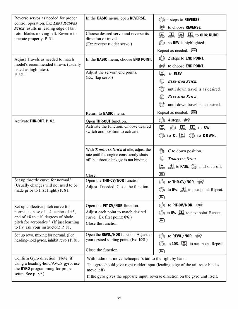
75
Reverse servos as needed for propercontrol operation. Ex: LEFT RUDDERSTICK results in leading edge of tailrotor blades moving left. Reverse tooperate properly. P. 31.
Adjust Travels as needed to matchmodel's recommended throws (usuallylisted as high rates).P. 32.
Activate THR-CUT. P. 82.
Set up throttle curve for normal.2
(Usually changes will not need to bemade prior to first flight.) P. 81.
Set up collective pitch curve fornormal as base of –4, center of +5,end of +8 to +10 degrees of bladepitch for aerobatics.2 (If just learningto fly, ask your instructor.) P. 81.
Set up revo. mixing for normal. (Forheading-hold gyros, inhibit revo.) P. 81.
Confirm Gyro direction. (Note: ifusing a heading-hold/AVCS gyro, usethe GYRO programming for propersetup. See p. 89.)
In the BASIC menu, open REVERSE.
Choose desired servo and reverse itsdirection of travel. (Ex: reverse rudder servo.)
In the BASIC menu, choose END POINT.
Adjust the servos’ end points.(Ex: flap servo)
Return to BASIC menu.
Open THR-CUT function.Activate the function. Choose desiredswitch and position to activate.
With THROTTLE STICK at idle, adjust therate until the engine consistently shutsoff, but throttle linkage is not binding.1
Close.Open the THR-CV/NOR function.Adjust if needed. Close the function.
Open the PIT-CV/NOR function. Adjust each point to match desiredcurve. (Ex first point: 8%.)Close the function.
Open the REVO./NOR function. Adjust toyour desired starting point. (Ex: 10%.)
Close the function.
4 steps to REVERSE.
to choose REVERSE.
to CH4: RUDD.
so REV is highlighted.
Repeat as needed.
2 steps to END POINT.
to choose END POINT.
to ELEV.
ELEVATOR STICK.
until down travel is as desired.
ELEVATOR STICK.
until down travel is as desired.
Repeat as needed.
4 steps.
to S W .
to C . to D O W N .
C to down position.
THROTTLE STICK.
to RATE. until shuts off.
to THR-CV/NOR.
to 5%. to next point. Repeat.
to PIT-CV/NOR.
to 8%. to next point. Repeat.
to REVO./NOR.
to 10%. to next point. Repeat.
With radio on, move helicopter’s tail to the right by hand. The gyro should give right rudder input (leading edge of the tail rotor bladesmove left).If the gyro gives the opposite input, reverse direction on the gyro unit itself.

1 Periodically move the throttle stick to full and back down to ensure proper servo settings.2 It is critical that dials A and C be centered when the pitch and throttle curves are setup.
76
Learn how to operate HOVERING PITCHand HOVERING THROTTLE. See p. 88.
Notice at half throttle, the VR(C) dialadjusts the throttle separately from thepitch. VR(A) adjusts the pitchseparately from the throttle.
for 1 second.(If ADVANCE, again.)
1 step to SERVO.
throttle to center
VR(C) VR(A) center dials.
Be sure to follow your model’s instructions for preflight checks, blade tracking, etc. Never assume a set of blades areproperly balanced and will track without checking.
Check receiver battery voltage! Always check voltage with a voltmeter prior to each and every engine start.(Never assume being plugged in all night means your radio gear is ready to fly). Insufficient charge, binding servo linkages,and other problems can result in a dangerous crash with the possibility of injury to yourself, others and property.
Confirm the swashplate is level at 0 travel. Adjust arms if needed.Apply full collective and check that the swashplate remained level and there is no binding. Repeat for full cyclic pitch androll. If not, adjust as needed to correct in END POINT: see p. 32.
Important note: prior to setting up throttle hold, idle-ups, offsets, etc, be sure to get your normal condition operating properly.
Where next?(Other functions you may wish to set up for your model.)THROTTLE HOLD: P. 83.SUB-TRIM p. 41 and separate trims for conditions (OFFSETS): p. 86.Governor setup: p. 89.IDLE-UP p. 85.DELAYS to ease servo response when switching idle-ups: p. 87.Rudder-to-throttle and other programmable mixes p. 59.
Checking setup prior to going airborne: Check voltage! Then, with the assistance of an instructor, and having completedall range checks, etc, gradually apply throttle until the helicopter becomes “light on the skids.” Adjust trims as needed tocorrect for any roll, pitch, or yaw tendencies. If the tail “wags,” the gyro gain is too high. Decrease gyro gain.

HELI-SPECIFIC BASIC MENU FUNCTIONS
MODEL TYPE: This function of the PARAMETER submenu is used to select the type of model programming to be used.Before doing anything else to set up your model, first you must decide which MODEL TYPE best fits your aircraft. Ifyour transmitter is a 9CA, the default is ACRO. If it is a 9CH, the default is HELI(SW1).
HELICOPTER SWASHPLATE TYPES:The 9C radios support 5 basic swashplate setups, including “single servo” (SW1 – most helicopters use this type) and 4types of CCPM (cyclic and collective pitch mixing). A “single servo” swashplate uses one servo for each axis: aileron,elevator (cyclic pitch), and collective pitch. CCPM helicopters utilize a combination of servos working together to achievethe 3 axes of motion. There are 4 basic CCPM types, displayed below. CCPM has several advantages, the most obviousof which is far less mechanical complexity to properly move the swashplate of the helicopter. Additionally, several servosworking in unison (ex: SR3, all 3 servos together create elevator movement) dramatically increases the torque available aswell as the precision and centering.
Please note that some helicopters are type SR-3 or SN-3, except off by 180 degrees. For example, the Kyosho® Caliber™ isSR-3 but with the 2 parallel servos to the rear of the helicopter, not front. If your model’s swashplate is off by 180 degrees,you will still use that swashplate type, but also use SWASH AFR (p.79) to adjust the functions as needed until it operatesproperly. Additionally, different angles of CCPM may also be created utilizing the fully assignable programmable mixes.(See our Frequently Asked Questions area at www.futaba-rc.com\faq\faq-9c.html for specific examples.)
Not operating quite like you expected? In many CCPM installations you need to either reverse the direction of a specificfunction (SWASH AFR) or reverse a single servo’s direction (REVERSE). See SWASH AFR for details.(p.79)
Swashplate Type Setting Procedure
HELISWH1 Type: Independent aileron, pitch and elevator servos linked to theswashplate. Most kits are HELISWH1 type.
HELI SWH2 Type: pushrods positioned as shown. Elevator operates with a mechanicallinkage. With Aileron inputs, the aileron and pitch servos tilt the swashplate left andright; with Pitch inputs, the aileron and pitch servos raise the swashplate up and down.
HELI SWH4 Type: pushrods positioned as shown. With Aileron inputs, the aileron andpitch servos tilt the swashplate left and right; with Elevator inputs, the servos tilt theswashplate fore and aft; with Pitch inputs, all four servos raise the swashplate up and down.
HELI SR-3 Type: pushrods positioned as shown. With Aileron inputs, the aileron andpitch servos tilt the swashplate left and right; with Elevator inputs, the three servos tiltthe swashplate fore and aft; with Pitch inputs, all three servos raise the swashplate upand down.
HELI SN-3 Type: pushrods positioned as shown. With Aileron inputs, the three servostilt the swashplate left and right; with Elevator inputs, the elevator and pitch servos tiltthe swashplate fore and aft; with Pitch inputs, all three servos raise the swashplate upand down.
Pitch Aileron
Front
Aileron Pitch
Front
(Pitch) (Aileron)
Elevator 1
Elevator 2(CH8)
Aileron(Pitch)
Pitch(Aileron)
Front
Elevator
120
120120
Aileron
Pitch
FrontElevator
120
120
120
77

GOAL of EXAMPLE: STEPS: INPUTS:
1Radio emits a repeating “beep” and shows progress on screen as the model memory is being copied. Note that if the power switch is turned off priorto completion, the data will not be copied.
78
Change the MODEL TYPE of model #3from aircraft to 120 degree CCPM with 2servos working in unison for collectivepitch and aileron [HELI(SR-3)].
Where next?
Confirm you are currently using theproper model memory. (example: 3)
Open PARAMETER submenu.
Change to the desired MODEL TYPE(example, SR3.)Confirm the change.
Close.
On home screen, check model nameand # on top left.If it is not the correct model (example:3), see MODEL SELECT, p. 25.
for 1 second.(If ADVANCE, again.)
to 2nd page of menu.
1 step to PARAMETER.
(example: 2 steps.)
for one second.
“sure?” displays. to confirm.1
If a single servo is not operating properly, REVERSE: see p. 31.If a control is operating backwards (i.e. Elevator), see SWASH AFR, p. 79.If unsure see SWASH AFR.

SWASH AFR [HELI(SWH2/4/SN-3, SR-3) only]:
Swashplate function rate settings (SWASH AFR) reduce/increase/reverse the rate (travel)of the aileron, elevator (except SWH2) and collective pitch functions, adjusting orreversing the motion of all servos involved in that function, only when using thatfunction. Since these types utilize multiple servos together to create the controls, simplyadjusting a servo’s REVERSE or END POINT would not properly correct the travel of anyone control. Since SW1 uses one servo for each function, there is no need for AFR in SW1.
This is fairly hard to explain but easy to see, so let’s set up Kyosho Caliber’s swashplate settings as an example. Witheverything installed per factory instructions, set the model to HELI(SR-3). Now let’s adjust the swashplate properly.
Since aileron always uses no more than 2 servos, check it first. Either both operate properly (no change needed), bothoperate backwards (reverse the whole function), or one servo operates backwards (reverse that servo alone).
Next check elevator. Remember, the aileron servo(s) operate correctly, so if elevator does not, we should only have 2choices left – the whole function needs to be reversed, or the servo(s) not shared with aileron need to be reversed.
Last is collective. If aileron and elevator are working properly, the only thing that could be wrong is the whole directioncollective operates (reverse the whole function). In our example, SR-3 is 180 degrees off from the swashplate of the Caliber.Therefore, it is very likely that several functions will not operate properly. The collective pitch operation is backwards; butreversing all three servos would also reverse the aileron and elevator operations. Changing the collective pitch rate,however, from +50% to –50%, will reverse the collective pitch without affecting the aileron action.
79

CHECKING FOR PROPER MOTION ON AN SR-3 SWASHPLATE
GOAL of EXAMPLE: STEPS: INPUTS:
80
Adjust the travel of the collective pitchfrom +50% to –23%, reversing thetravel of all 3 servos and decreasingtheir travel in collective pitch only, onan SR-3 MODEL TYPE.
Where next?
Open SWASH AFR function.
Adjust PIT travel to –23.
Close the menu.
for 1 second.(If ADVANCE, again.)
to SWASH AFR.
to –23%.
Confirm the swashplate is level at 0 travel. Adjust arms if needed.Apply full collective and check that the swashplate remained level. If not, adjustservo’s travels as needed to correct. END POINT: see p. 32.Set up the normal condition: (TH-CV/NOR, PI-CV/NOR, REVO./NOR): see p. 81.Set up D/R,EXP: see p. 35.
SR-3 Swash Type
AILERON STICK.
ELEVATOR STICK.
RUDDER STICK.
THROTTLE STICK.
PROPER MOTION
Swashplate tilts right.
Front of swash plate movesdown; back of swashplatemoves up.
The leading edges of tailblades rotate left.Entire Swashplate lifts.
WRONG MOTION
Swashplate tilts left.
Back of Swashplate moves up.
Back of Swashplate movesdown.Swashplate moves theopposite.Entire swashplate moves up.
Blades rotated right.
Swashplate lowers.
HOW TO FIX
Reverse AIL setting inSWASH to -50%.Ch6 servo movesincorrectly; REVERSE.Ch1 servo movesincorrectly; REVERSE.Reverse ELE setting in SWASH. (ex: +50 to –50)Ch2 servo movesincorrectly; REVERSE.REVERSE the rudder servo.
Reverse PIT setting in SWASH.
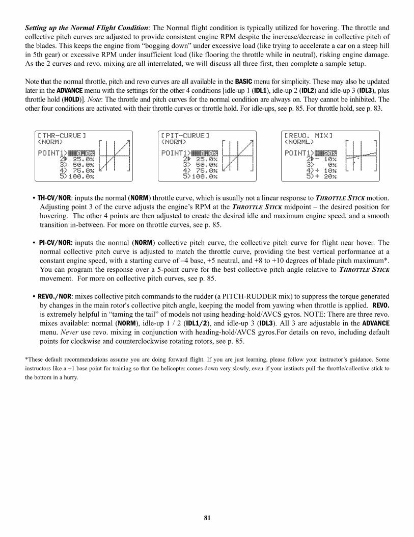
Setting up the Normal Flight Condition: The Normal flight condition is typically utilized for hovering. The throttle andcollective pitch curves are adjusted to provide consistent engine RPM despite the increase/decrease in collective pitch ofthe blades. This keeps the engine from “bogging down” under excessive load (like trying to accelerate a car on a steep hillin 5th gear) or excessive RPM under insufficient load (like flooring the throttle while in neutral), risking engine damage.As the 2 curves and revo. mixing are all interrelated, we will discuss all three first, then complete a sample setup.
Note that the normal throttle, pitch and revo curves are all available in the BASIC menu for simplicity. These may also be updatedlater in the ADVANCE menu with the settings for the other 4 conditions [idle-up 1 (IDL1), idle-up 2 (IDL2) and idle-up 3 (IDL3), plusthrottle hold (HOLD)]. Note: The throttle and pitch curves for the normal condition are always on. They cannot be inhibited. Theother four conditions are activated with their throttle curves or throttle hold. For idle-ups, see p. 85. For throttle hold, see p. 83.
• TH-CV/NOR: inputs the normal (NORM) throttle curve, which is usually not a linear response to THROTTLE STICK motion.Adjusting point 3 of the curve adjusts the engine’s RPM at the THROTTLE STICK midpoint – the desired position forhovering. The other 4 points are then adjusted to create the desired idle and maximum engine speed, and a smoothtransition in-between. For more on throttle curves, see p. 85.
• PI-CV/NOR: inputs the normal (NORM) collective pitch curve, the collective pitch curve for flight near hover. Thenormal collective pitch curve is adjusted to match the throttle curve, providing the best vertical performance at aconstant engine speed, with a starting curve of –4 base, +5 neutral, and +8 to +10 degrees of blade pitch maximum*.You can program the response over a 5-point curve for the best collective pitch angle relative to THROTTLE STICKmovement. For more on collective pitch curves, see p. 85.
• REVO./NOR: mixes collective pitch commands to the rudder (a PITCH-RUDDER mix) to suppress the torque generatedby changes in the main rotor's collective pitch angle, keeping the model from yawing when throttle is applied. REVO.is extremely helpful in “taming the tail” of models not using heading-hold/AVCS gyros. NOTE: There are three revo.mixes available: normal (NORM), idle-up 1 / 2 (IDL1/2), and idle-up 3 (IDL3). All 3 are adjustable in the ADVANCEmenu. Never use revo. mixing in conjunction with heading-hold/AVCS gyros.For details on revo, including defaultpoints for clockwise and counterclockwise rotating rotors, see p. 85.
*These default recommendations assume you are doing forward flight. If you are just learning, please follow your instructor’s guidance. Someinstructors like a +1 base point for training so that the helicopter comes down very slowly, even if your instincts pull the throttle/collective stick tothe bottom in a hurry.
81
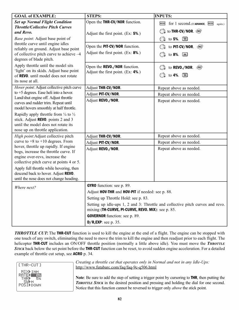
GOAL of EXAMPLE: STEPS: INPUTS:
THROTTLE CUT: The THR-CUT function is used to kill the engine at the end of a flight. The engine can be stopped withone touch of any switch, eliminating the need to move the trim to kill the engine and then readjust prior to each flight. Thehelicopter THR-CUT includes an ON/OFF throttle position (normally a little above idle). You must move the THROTTLESTICK back below the set point before the THR-CUT function can be reset, to avoid sudden engine acceleration. For a detailedexample of throttle cut setup, see ACRO p. 34.
Creating a throttle cut that operates only in Normal and not in any Idle-Ups:http://www.futabarc.com/faq/faq-9c-q506.html
Note: Be sure to add the step of setting a trigger point by cursoring to THR, then putting theTHROTTLE STICK in the desired position and pressing and holding the dial for one second.Notice that this function cannot be reversed to trigger only above the stick point.
82
Set up Normal Flight ConditionThrottle/Collective Pitch Curves and Revo.Base point: Adjust base point ofthrottle curve until engine idlesreliably on ground. Adjust base pointof collective pitch curve to achieve –4degrees of blade pitch.Apply throttle until the model sits‘light’ on its skids. Adjust base pointof REVO. until model does not rotateits nose at all.Hover point: Adjust collective pitch curveto +5 degrees. Ease heli into a hover.Land/shut engine off. Adjust throttlecurves and rudder trim. Repeat untilmodel hovers smoothly at half throttle.Rapidly apply throttle from ¼ to ½stick. Adjust REVO. points 2 and 3until the model does not rotate itsnose up on throttle application.High point:Adjust collective pitchcurve to +8 to +10 degrees. Fromhover, throttle up rapidly. If enginebogs, increase the throttle curve. Ifengine over-revs, increase thecollective pitch curve at points 4 or 5.Apply full throttle while hovering, thendescend back to hover. Adjust REVO.until the nose does not change heading.
Where next?
Open the THR-CV/NOR function.
Adjust the first point. (Ex: 5%.)
Open the PIT-CV/NOR function. Adjust the first point. (Ex: 8%.)
Open the REVO./NOR function.Adjust the first point. (Ex: 4%.)
Adjust THR-CV/NOR.Adjust PIT-CV/NOR.Adjust REVO./NOR.
Adjust THR-CV/NOR.Adjust PIT-CV/NOR.Adjust REVO./NOR.
for 1 second.(If ADVANCE, again.)
to THR-CV/NOR.
to 5%.
to PIT-CV/NOR.
to 8%.
to REVO./NOR.
to 4%.
Repeat above as needed.Repeat above as needed.Repeat above as needed.
Repeat above as needed.Repeat above as needed.Repeat above as needed.
GYRO function: see p. 89.Adjust HOV-THR and HOV-PIT if needed: see p. 88.Setting up Throttle Hold: see p. 83.Setting up idle-ups 1, 2 and 3: Throttle and collective pitch curves and revo.mixing (TH-CURVE, PI-CURVE, REVO. MIX): see p. 85.GOVERNOR function: see p. 89.D/R,EXP: see p. 35.

HELI-SPECIFIC ADVANCE MENU FUNCTIONS
THR-HOLD: This function holds the engine in the idling position and disengages it from the THROTTLE STICK when SWITCHE (9CH) or G (9CA) is moved. It is commonly used to practice auto-rotation.
Prior to setting up THR-HOLD, hook up the throttle linkage so that the carburetor isopened fully at high throttle, then use the digital trim to adjust the engine idleposition. To have THR- HOLD maintain idle, move the THROTTLE STICK to the idleposition, then move the hold SWITCH on and off and keep changing the offset valueuntil the servo does not move. To lower the engine idle speed, or if you want to shutoff, input a more negative number.
Adjustability:• Idling position: Range of –50% to +50% centered about the throttle idle position to get the desired engine RPM.• Rudder offset: Offsets the tail rotor pitch. Keeps the fuselage from rotating in throttle hold.• Time delay: A rudder offset time delay may be set up within the DELAY function (see p. 87) to ease in rudder and
prevent tail wag. • Switch assignment: Assigned to SWITCH G (9CA) or E (9CH) down. Not adjustable.• Throttle curve: Since the throttle is moved to a single preset position, no curve is available for THR-HOLD.• Collective pitch curve: Independent curve, typically adjusted to create a blade pitch range of -4° to +10° to +12°, is
automatically activated with THR-HOLD.• Revo. mix: Since revo. mix adjusts for torque from the engine, no revo. mix is available for THR-HOLD.• Priority: The throttle hold function has priority over idle-up. Be sure that the throttle hold and idle-up SWITCHES are in the
desired positions before trying to start the engine. (We recommend starting your engine in throttle hold for safety reasons.)• Gyro: Gyro programming includes an option to have a separate gyro setting for each condition, including THR-HOLD.
This avoids the potential problem of the user being in the wrong gyro setting when going to THR-HOLD, resulting in animproper rudder offset and the model pirouetting.
GOAL of EXAMPLE: STEPS: INPUTS:
83
Set up throttle hold.
Determine desired throttle position byidling engine, turn on THR-HOLD, andadjust percentage as required to reachthe desired running point.
Where next?
Open THR-HOLD function.
Activate the function.Set desired engine position.Optional: set up a rudder offset. (If aslowed reaction is desired, go to DELAY.)Close.
for 1 second.(If basic, again.)
to THR-HOLD.
to OFF.
to desired percent.
to OFF. to desired offset.
PIT-CURVE for THR-HOLD: see p. 85.DELAY for THR-HOLD (to ease collective pitch response): see p. 87.GYRO setup: see p. 89.Setting up the Idle-Ups: Throttle and Collective pitch Curves and Revo. Mixing(TH-CURVE, PIT-CURVE, REVO. MIXING) for idle-ups: see p. 85.D/R,EXP: see p. 35.
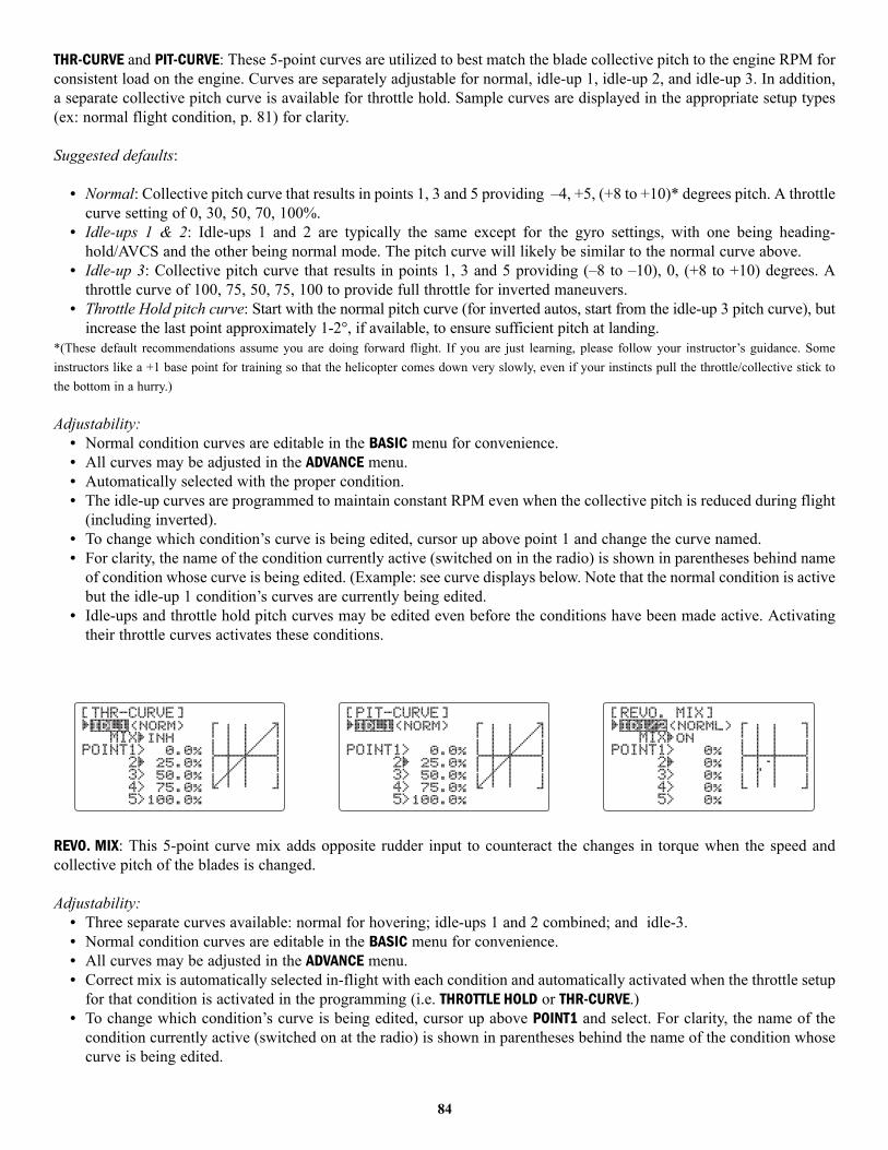
THR-CURVE and PIT-CURVE: These 5-point curves are utilized to best match the blade collective pitch to the engine RPM forconsistent load on the engine. Curves are separately adjustable for normal, idle-up 1, idle-up 2, and idle-up 3. In addition,a separate collective pitch curve is available for throttle hold. Sample curves are displayed in the appropriate setup types(ex: normal flight condition, p. 81) for clarity.
Suggested defaults:
• Normal: Collective pitch curve that results in points 1, 3 and 5 providing –4, +5, (+8 to +10)* degrees pitch. A throttlecurve setting of 0, 30, 50, 70, 100%.
• Idle-ups 1 & 2: Idle-ups 1 and 2 are typically the same except for the gyro settings, with one being heading-hold/AVCS and the other being normal mode. The pitch curve will likely be similar to the normal curve above.
• Idle-up 3: Collective pitch curve that results in points 1, 3 and 5 providing (–8 to –10), 0, (+8 to +10) degrees. Athrottle curve of 100, 75, 50, 75, 100 to provide full throttle for inverted maneuvers.
• Throttle Hold pitch curve: Start with the normal pitch curve (for inverted autos, start from the idle-up 3 pitch curve), butincrease the last point approximately 1-2°, if available, to ensure sufficient pitch at landing.
*(These default recommendations assume you are doing forward flight. If you are just learning, please follow your instructor’s guidance. Someinstructors like a +1 base point for training so that the helicopter comes down very slowly, even if your instincts pull the throttle/collective stick tothe bottom in a hurry.)
Adjustability:• Normal condition curves are editable in the BASIC menu for convenience.• All curves may be adjusted in the ADVANCE menu. • Automatically selected with the proper condition.• The idle-up curves are programmed to maintain constant RPM even when the collective pitch is reduced during flight
(including inverted). • To change which condition’s curve is being edited, cursor up above point 1 and change the curve named. • For clarity, the name of the condition currently active (switched on in the radio) is shown in parentheses behind name
of condition whose curve is being edited. (Example: see curve displays below. Note that the normal condition is activebut the idle-up 1 condition’s curves are currently being edited.
• Idle-ups and throttle hold pitch curves may be edited even before the conditions have been made active. Activatingtheir throttle curves activates these conditions.
REVO. MIX: This 5-point curve mix adds opposite rudder input to counteract the changes in torque when the speed andcollective pitch of the blades is changed.
Adjustability:• Three separate curves available: normal for hovering; idle-ups 1 and 2 combined; and idle-3.• Normal condition curves are editable in the BASIC menu for convenience.• All curves may be adjusted in the ADVANCE menu. • Correct mix is automatically selected in-flight with each condition and automatically activated when the throttle setup
for that condition is activated in the programming (i.e. THROTTLE HOLD or THR-CURVE.)• To change which condition’s curve is being edited, cursor up above POINT1 and select. For clarity, the name of the
condition currently active (switched on at the radio) is shown in parentheses behind the name of the condition whosecurve is being edited.
84
• Revo. mixing rates are 5-point curves. For a clockwise-turning rotor, the rudder is mixed in the clockwise directionwhen collective pitch is increased; for counterclockwise-turning, the opposite. Change the operating direction settingby changing the signs of the numbers in the curve from plus (+) to minus (–) and vice versa. Suggested defaults:
• Clockwise rotation: -20, -10, 0, +10, +20% from low throttle to high.• Counterclockwise rotation: +20, +10, 0, -10, -20% from low throttle to high.• Adjust to the actual values that work best for your model.
• Revo. curves for idle-ups are often v-shaped to provide proper rudder input with negative pitch and increased throttleduring inverted flight. (Rudder is needed to counter the reaction whenever there is increased torque. In inverted flight,throttle stick below half has increased throttle and negative pitch, therefore increasing torque and rotating thehelicopter unless the revo. mix is also increasing appropriately.)
IDLE-UPS: additional flight conditions available specifically for helicopters. These additional flight conditions containdifferent throttle curves, collective pitch curves, revo. mixing, and trims (except IDLE-3) to make the helicopter performcertain maneuvers more easily. Lastly, the gyro and dual rate functions may be set to provide separate rates per conditionselected, including one for each idle-up.
One of the most common flight conditions can easily flip from upright to inverted and back. To do so, the pitch curve isset to 0 pitch at half stick, positive pitch (climb upright) above half, and negative pitch (climb when inverted) below halfstick. The throttle curve is adjusted to allow the engine to run consistently throughout the changes in pitch.
Additional idle-ups may be used to maximize the helicopter’s flight characteristics in certain types of flight (i.e. fastforward motion, backward) or maneuvers (loops, rolls, stall turns), or even the same maneuver but changing from heading-hold/AVCS gyro mode to normal gyro mode. The 9C provides 3 idle-ups to allow the modeler 3 additional setups alongwith the normal flight condition. (Note that IDL3 does not include governor settings.)
Adjustability:• SWITCH G (9CA) or E (9CH) is programmed for normal (NORM), idle-up 1 (IDL1), and idle-up 2 (IDL2) curves. This
switch/position assignment is not adjustable.• Activated with the throttle curve for that condition in THR-CURVE.• Curves are adjusted to maintain constant RPM even when the collective pitch is negative (inverted). • Note that REVO. mixing has one curve for idle-ups 1 and 2 and a second curve just for idle-up3.• Gyro settings may be set separately for each idle-up. (See p. 89.)• Governor settings may be set up to follow Normal/Idle1/Idle2, but do not offer a setting to adjust for each of the 5
conditions like gyro. (See p. 89.)• Activating OFFSET makes the TRIM LEVERS adjust the trim separately in each of the idle-up conditions.
For an example of throttle and pitch curves and revo, please see Normal Flight Condition Setup, p. 81.
85
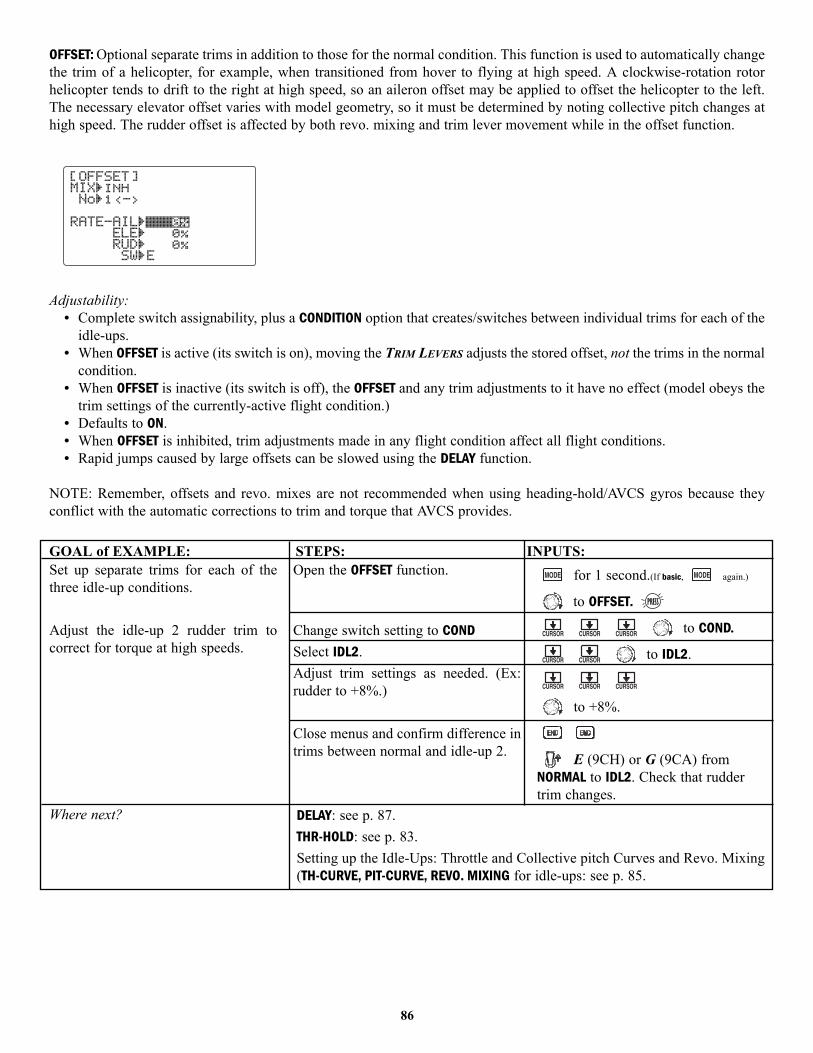
OFFSET: Optional separate trims in addition to those for the normal condition. This function is used to automatically changethe trim of a helicopter, for example, when transitioned from hover to flying at high speed. A clockwise-rotation rotorhelicopter tends to drift to the right at high speed, so an aileron offset may be applied to offset the helicopter to the left.The necessary elevator offset varies with model geometry, so it must be determined by noting collective pitch changes athigh speed. The rudder offset is affected by both revo. mixing and trim lever movement while in the offset function.
Adjustability:• Complete switch assignability, plus a CONDITION option that creates/switches between individual trims for each of the
idle-ups.• When OFFSET is active (its switch is on), moving the TRIM LEVERS adjusts the stored offset, not the trims in the normal
condition. • When OFFSET is inactive (its switch is off), the OFFSET and any trim adjustments to it have no effect (model obeys the
trim settings of the currently-active flight condition.)• Defaults to ON.• When OFFSET is inhibited, trim adjustments made in any flight condition affect all flight conditions.• Rapid jumps caused by large offsets can be slowed using the DELAY function.
NOTE: Remember, offsets and revo. mixes are not recommended when using heading-hold/AVCS gyros because theyconflict with the automatic corrections to trim and torque that AVCS provides.
GOAL of EXAMPLE: STEPS: INPUTS:
86
Set up separate trims for each of thethree idle-up conditions.
Adjust the idle-up 2 rudder trim tocorrect for torque at high speeds.
Where next?
Open the OFFSET function.
Change switch setting to CONDSelect IDL2.Adjust trim settings as needed. (Ex:rudder to +8%.)
Close menus and confirm difference intrims between normal and idle-up 2.
for 1 second.(If basic, again.)
to OFFSET.
to COND.
to IDL2.
to +8%.
E (9CH) or G (9CA) fromNORMAL to IDL2. Check that ruddertrim changes.
DELAY: see p. 87.THR-HOLD: see p. 83.Setting up the Idle-Ups: Throttle and Collective pitch Curves and Revo. Mixing(TH-CURVE, PIT-CURVE, REVO. MIXING for idle-ups: see p. 85.
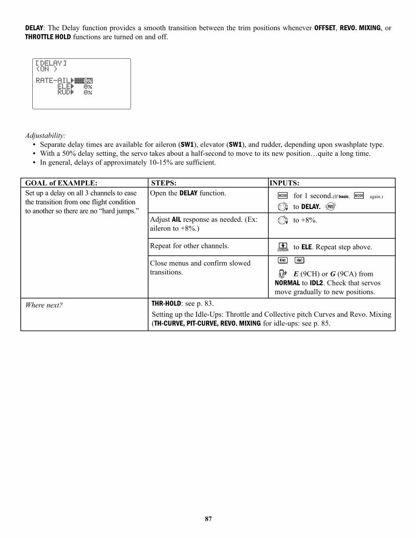
DELAY: The Delay function provides a smooth transition between the trim positions whenever OFFSET, REVO. MIXING, orTHROTTLE HOLD functions are turned on and off.
Adjustability:• Separate delay times are available for aileron (SW1), elevator (SW1), and rudder, depending upon swashplate type. • With a 50% delay setting, the servo takes about a half-second to move to its new position…quite a long time.• In general, delays of approximately 10-15% are sufficient.
GOAL of EXAMPLE: STEPS: INPUTS:
87
Set up a delay on all 3 channels to easethe transition from one flight conditionto another so there are no “hard jumps.”
Where next?
Open the DELAY function.
Adjust AIL response as needed. (Ex:aileron to +8%.)
Repeat for other channels.
Close menus and confirm slowedtransitions.
for 1 second.(If basic, again.)
to DELAY.
to +8%.
to ELE. Repeat step above.
E (9CH) or G (9CA) fromNORMAL to IDL2. Check that servosmove gradually to new positions.
THR-HOLD: see p. 83.Setting up the Idle-Ups: Throttle and Collective pitch Curves and Revo. Mixing(TH-CURVE, PIT-CURVE, REVO. MIXING for idle-ups: see p. 85.
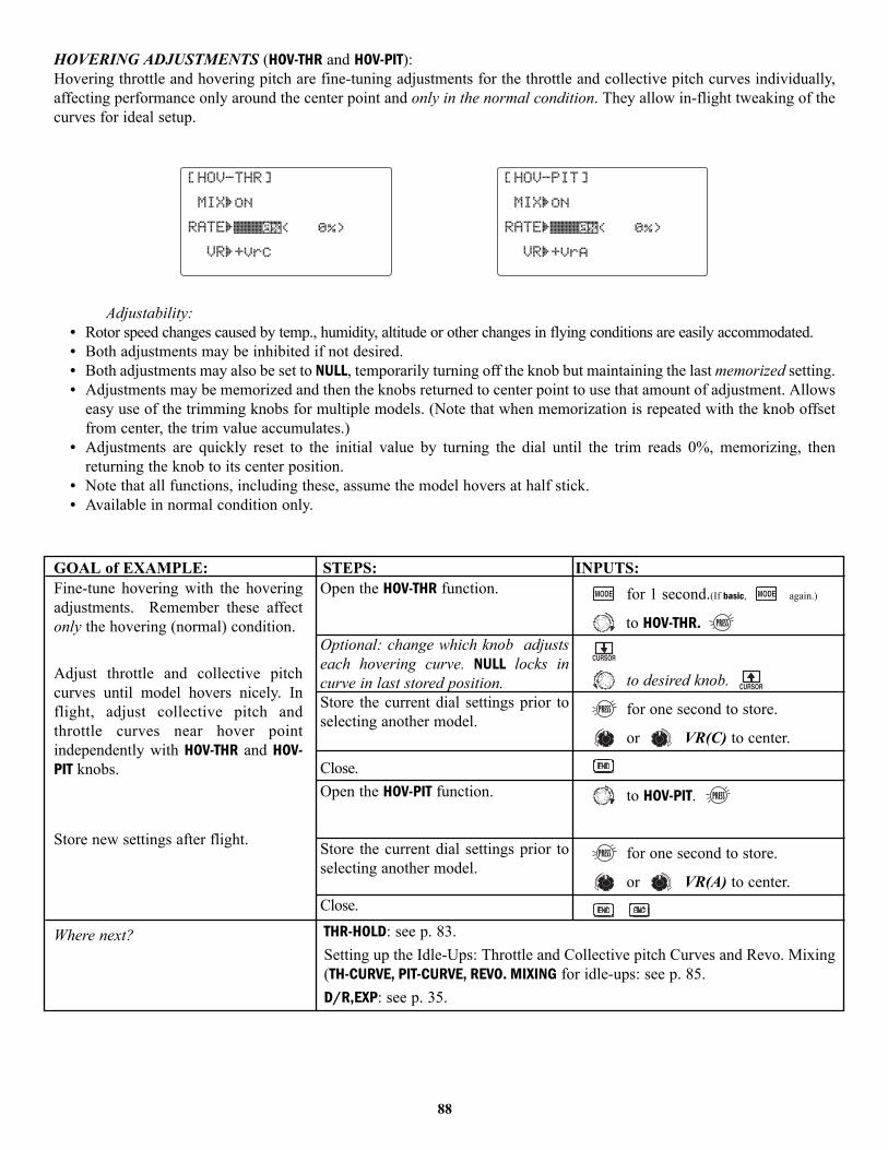
HOVERING ADJUSTMENTS (HOV-THR and HOV-PIT):Hovering throttle and hovering pitch are fine-tuning adjustments for the throttle and collective pitch curves individually,affecting performance only around the center point and only in the normal condition. They allow in-flight tweaking of thecurves for ideal setup.
Adjustability:• Rotor speed changes caused by temp., humidity, altitude or other changes in flying conditions are easily accommodated.• Both adjustments may be inhibited if not desired.• Both adjustments may also be set to NULL, temporarily turning off the knob but maintaining the last memorized setting.• Adjustments may be memorized and then the knobs returned to center point to use that amount of adjustment. Allows
easy use of the trimming knobs for multiple models. (Note that when memorization is repeated with the knob offsetfrom center, the trim value accumulates.)
• Adjustments are quickly reset to the initial value by turning the dial until the trim reads 0%, memorizing, thenreturning the knob to its center position.
• Note that all functions, including these, assume the model hovers at half stick. • Available in normal condition only.
GOAL of EXAMPLE: STEPS: INPUTS:
88
Fine-tune hovering with the hoveringadjustments. Remember these affectonly the hovering (normal) condition.
Adjust throttle and collective pitchcurves until model hovers nicely. Inflight, adjust collective pitch andthrottle curves near hover pointindependently with HOV-THR and HOV-PIT knobs.
Store new settings after flight.
Where next?
Open the HOV-THR function.
Optional: change which knob adjustseach hovering curve. NULL locks incurve in last stored position.Store the current dial settings prior toselecting another model.
Close.Open the HOV-PIT function.
Store the current dial settings prior toselecting another model.
Close.
for 1 second.(If basic, again.)
to HOV-THR.
to desired knob.
for one second to store.
or VR(C) to center.
to HOV-PIT.
for one second to store.
or VR(A) to center.
THR-HOLD: see p. 83.Setting up the Idle-Ups: Throttle and Collective pitch Curves and Revo. Mixing(TH-CURVE, PIT-CURVE, REVO. MIXING for idle-ups: see p. 85.D/R,EXP: see p. 35.

GYROS and GOVERNORS: Using electronics to take some of the complexity out of setups and flight.
What is a gyro? A gyroscope is an electronic unit that senses motion and corrects for it. For example, if the wind blowsyour helicopter’s tail to the left, a gyro will sense that motion (and confirm that no input was given) and will correct for it.
How does it help in helicopter setup? A good gyro will totally eliminate the need for revo. mixing. The gyro will senseand correct the unwanted motion for you, so you don’t have to spend time to get a complex curve operating properly.
Gyro sensor kinds: There are many different kinds of gyros. Early gyros were mechanical, with a spinning drum similarto a child’s gyroscope toy. The next generation utilized a special type of crystal, called piezoelectric, which sensed themotion and provided an electrical pulse. The finest gyros at the time of this writing are SMM technology. These siliconemicro machines, or computer chips, sense the motion. SMM is far more accurate and less susceptible to inaccuraciescaused by temperature changes, etc.
Types of gyro responses:• Normal: sense motion and dampen it (if the gyro rotates off course for 2 seconds, it corrects for 2 seconds).• Heading-hold/AVCS: calculate the angle of rotation (by tracking the time/rate of change) and then provide correction
until the same rotation is achieved. • Stick priority: a feature on most high-end gyros. The more input given on the channel the gyro controls, the less
sensitive the gain is automatically. This way, if you give a large input for a stall turn, for example, the gyro turns itselfoff and does not fight the stall turn. As you ease off the rudder, the gain increases again, minimizing tail wag andkeeping the model straight. (If your gyro does not include stick priority, you can manually create it. Please seewww.futaba-rc.com\faq\faq-9c.html.)
Choosing the right gyro for your skills, your helicopter, and your budget:• Mechanical: some are still available. They are very challenging to set up and not as reliable as piezo or SMM.• Non-Heading-Hold Piezo: these are now inexpensive gyros that are reliable and easy to set up. Some have dual rates
and remote gain control to adjust sensitivity in flight. Lack heading-hold capabilities for precision flying.• Heading-Hold Piezo: Until recently, the cream of the crop. Expensive, and more complex to set up. Adds GPS-like heading
recognition. Exhibits minor difficulties with temperature drift (position setting varying with unit’s temperature).• Heading-Hold SMM: 21st Century gyro technology. Computer chip technology. Expensive, easier set up, higher durability.
Significant decrease in temperature sensitivity. Many include frame rate settings to allow faster response when usingspecialized digital servos. Examples:
• GY401: Simpler set up. Ideal for learning aerobatics through 3D.• GY502: Better centering than 401 for more advanced aerobatics. Ideal through Class III competition.• GY601: Exceptional center. Extremely fast response time. Requires specialized servo.
GYRO: simplifies adjusting/selecting the gyro sensitivity, and can provide more than 2 gyro gain settings. (The higher thegain, the more correction the gyro provides and the “softer” or less responsive the helicopter feels.) This functionmakes the best possible use of the inflight adjustable gain of most gyros..
Adjustability:
• Plug the gyro’s sensitivity adjustment to channel 5 of the receiver. (not assignable)• STD and AVCS/Heading-hold (GY) setup types available to simplify adjustments for AVCS/Heading-hold gyros. • Full switch assignability or may select Cond. option.• Cond. option provides separate gyro settings, one for each condition, automatically selected with the condition. Allows
changes in gain to meet the specific needs of each flight condition.• Each gyro setting may be set from –100 to +100 gain, equating to ATV settings of –100% to +100%.• Dual mode gyros (heading-hold/AVCS and normal) are easily triggered to each mode by changing the gyro setting’s
sign. Negative settings trigger normal mode; positive settings are AVCS mode.• Larger percentages indicate more gain, or gyro responsiveness.• Tail wagging or shaking indicates excessive gain settings. Turn down gyro setting until wag stops.
89
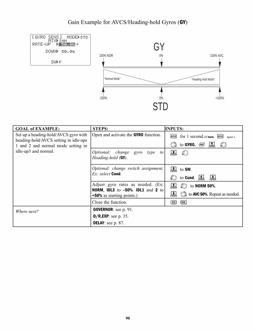
Gain Example for AVCS/Heading-hold Gyros (GY)
GOAL of EXAMPLE: STEPS: INPUTS:
0%-100% +100%
"Heading Hold Mode""Normal Mode"
100% NOR 0% 100% AVC
GY
STD
90
Set up a heading-hold/AVCS gyro withheading-hold/AVCS setting in idle-ups1 and 2 and normal mode setting inidle-up3 and normal.
Where next?
Open and activate the GYRO function.
Optional: change gyro type toHeading-hold (GY).
Optional: change switch assignment.Ex: select Cond.
Adjust gyro rates as needed. (Ex:NORM, IDL3 to –50%. IDL1 and 2 to+50% as starting points.)Close the function.
for 1 second.(If basic, again.)
to GYRO.
to SW.
to Cond.
to NORM 50%.
to AVC 50%. Repeat as needed.
GOVERNOR: see p. 91.D/R,EXP: see p. 35.DELAY: see p. 87.
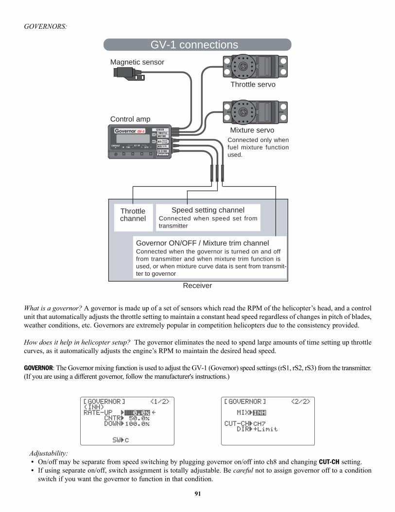
GOVERNORS:
What is a governor? A governor is made up of a set of sensors which read the RPM of the helicopter’s head, and a controlunit that automatically adjusts the throttle setting to maintain a constant head speed regardless of changes in pitch of blades,weather conditions, etc. Governors are extremely popular in competition helicopters due to the consistency provided.
How does it help in helicopter setup? The governor eliminates the need to spend large amounts of time setting up throttlecurves, as it automatically adjusts the engine’s RPM to maintain the desired head speed.
GOVERNOR: The Governor mixing function is used to adjust the GV-1 (Governor) speed settings (rS1, rS2, rS3) from the transmitter.(If you are using a different governor, follow the manufacturer's instructions.)
Adjustability:• On/off may be separate from speed switching by plugging governor on/off into ch8 and changing CUT-CH setting.• If using separate on/off, switch assignment is totally adjustable. Be careful not to assign governor off to a condition
switch if you want the governor to function in that condition.
GV-1 connections
Magnetic sensor
Throttle servo
Control amp
Mixture servoConnected only whenfuel mixture functionused.
Throttlechannel
Speed setting channelConnected when speed set fromtransmitter
Governor ON/OFF / Mixture trim channelConnected when the governor is turned on and offfrom transmitter and when mixture trim function isused, or when mixture curve data is sent from transmit-ter to governor
Receiver
91
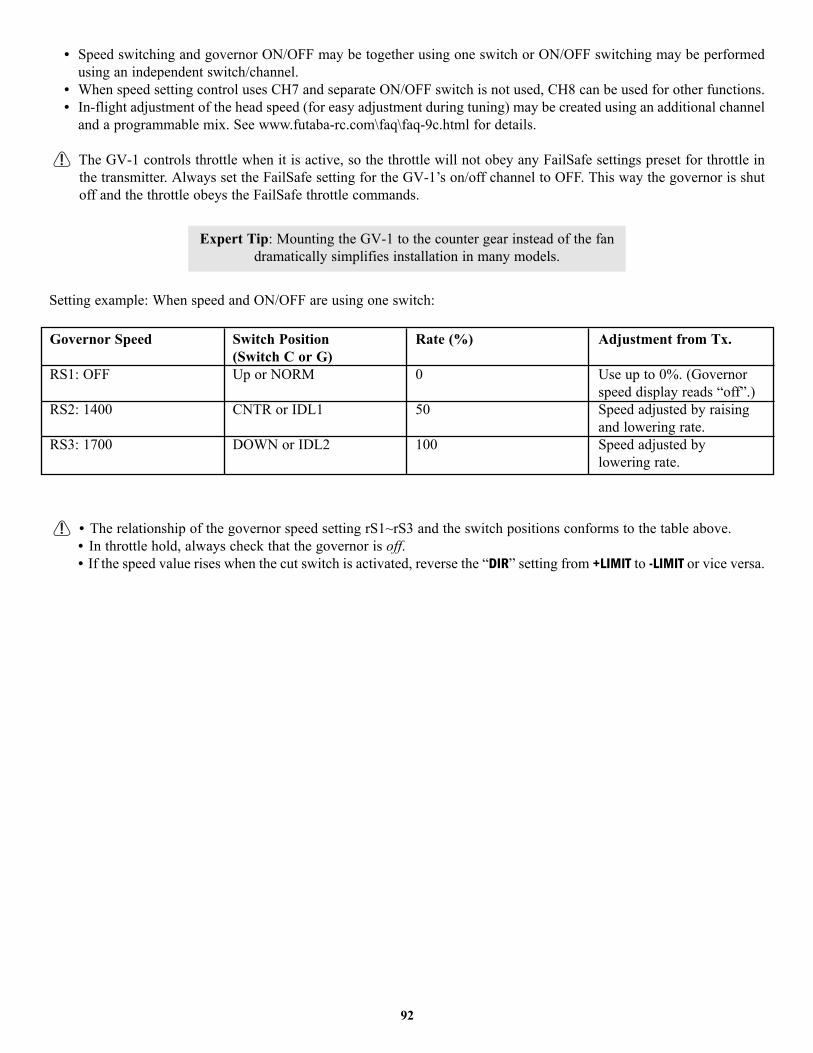
• Speed switching and governor ON/OFF may be together using one switch or ON/OFF switching may be performedusing an independent switch/channel.
• When speed setting control uses CH7 and separate ON/OFF switch is not used, CH8 can be used for other functions.• In-flight adjustment of the head speed (for easy adjustment during tuning) may be created using an additional channel
and a programmable mix. See www.futaba-rc.com\faq\faq-9c.html for details.
The GV-1 controls throttle when it is active, so the throttle will not obey any FailSafe settings preset for throttle inthe transmitter. Always set the FailSafe setting for the GV-1’s on/off channel to OFF. This way the governor is shutoff and the throttle obeys the FailSafe throttle commands.
Setting example: When speed and ON/OFF are using one switch:
• The relationship of the governor speed setting rS1~rS3 and the switch positions conforms to the table above.• In throttle hold, always check that the governor is off. • If the speed value rises when the cut switch is activated, reverse the “DIR” setting from +LIMIT to -LIMIT or vice versa.
Expert Tip: Mounting the GV-1 to the counter gear instead of the fan dramatically simplifies installation in many models.
92
Governor Speed
RS1: OFF
RS2: 1400
RS3: 1700
Switch Position(Switch C or G)Up or NORM
CNTR or IDL1
DOWN or IDL2
Rate (%)
0
50
100
Adjustment from Tx.
Use up to 0%. (Governorspeed display reads “off”.)Speed adjusted by raisingand lowering rate.Speed adjusted by lowering rate.

GOAL of EXAMPLE: STEPS: INPUTS:
93
Set up a GV1 governor to use bothchannels into the receiver and switchbetween the governor settingsautomatically when changing conditions.
Consider setting the battery FailSafesettings and other helpful functions onthe GV-1 itself.
Where next?
Open and activate the GOVERNORfunction.
Optional: change cut-off channel tochannel 8 and assign switch anddirection for on/off (channel 8).
Optional: change switch assignmentto select governor settings. Ex: selectswitch that selects the conditions.Adjust governor speed settings perswitch position or condition as needed.(Ex: defaults are fine.) Allows headspeed adjustment from transmitter.Close the function.
for 1 second.(If basic, again.)
to GOVERNOR.
to ACT.
to CH8.
to - if opposite switch
direction is desired.
to desired SWITCH.
to SW.
to G.
to each SWITCH position.
or as needed.
to next SWITCH position. Repeat.
GYRO: see p. 89.Adjust FailSafe (F/S) settings (p. 43).Adjust idle-up 3 collective pitch curve for same rates of climb upright/inverted.See p. 85.Adjust elevator/aileron response to fit your flying style: see D/R,EXP and ENDPOINT/SWASH AFR: pp. 35, 32, 79.

94
GLOSSARY
3D: Common name for certain types of aerobatic maneuvers. Aircraft: flying below the model’s stall speed, such astorque rolls. Helicopters: combining 2 or more maneuvers, such as rolling loop.
4.8V: 4.8 volt battery pack, made of 4 Ni-Cd 1.2V cells. See Accessories.
5-cell: 6.0 volt battery pack, made of 4 alkaline cells or 5 Ni-Cd cells. See Accessories.
6V (6Volt): battery pack, made of 4 alkaline cells or 5 Ni-Cd cells. See Accessories.
ACCELERATION: a delay mix which richens engine mixture and then returns to normal to compensate for abrupt throttlechanges. See THR-NEEDLE. . . . . . . . . . . . . . . . . . . . . . . . . . . . . . . . . . . . . . . . . . . . . . . . . . . . . . . . . . . . . . . . . . . . . . .56
Accessories: additional optional items which may be used with your 9C. . . . . . . . . . . . . . . . . . . . . . . . . . . . . . . . . . .10
ACRO: model type designed for use with powered aircraft. Selected in the MODEL submenu under TYPE . . . . . . . . . . ..29
ACRO vs GLID comparison. . . . . . . . . . . . . . . . . . . . . . . . . . . . . . . . . . . . . . . . . . . . . . . . . . . . . . . . . . . . . . . . . . . . . . .29
ACT. Active. Make a feature able to be utilized. Opposite of INH. Only visible in certain features.
Adjustable Function Rate: see SWASH AFR.
Adjustable Servo Travel (AST): a specific type of end point adjustment. See END POINT.
Adjustable Travel Limited (ATL): End point adjustment for low end only, for throttle channel. See ATL.
Adjustable Travel Volume (ATV): an older, less specific term for end point adjustment. See END POINT.
ADVANCE menus: Specific menus for each model type which allow the modeler to access and program the radio’s moreadvanced features.
AFR: Adjustable function rate. Used only in HELI model types with CCPM heads. See SWASH AFR.
AIL-2: second aileron servo assignment. See Twin aileron servos.
AIL1/2/3/4: Designation for the individual servos that are being commanded by the aileron command. Ex: when usingailevators, the two elevator servos are also acting as ailerons 3 and 4 (unless you set their values to 0). See Twin aileronservos and Twin elevator servos.
Aileron: surface that controls the roll of the model. Also called cyclic roll on a helicopter.
Aileron-to-flap mixing: Mixing used to create full-span aileron action. Not a preprogrammed mix. See Programmablemix. This is the default setup of one mix in GLID.
Aileron-to-rudder mix: Mixing that automatically creates a “coordinated turn”. Not a preprogrammed mix. SeeProgrammable mix. This is the default setup of one curve mix in HELI / GLID.
Aileron Differential: Decreased down aileron travel when compared to up aileron travel. Minimizes “dragging” the lowwing and creates more axial rolls. See Twin aileron servos. . . . . . . . . . . . . . . . . . . . . . . . . . . . . . . . . . . . . . . . . . . . .44
Ailevator: two elevators on separate channels, also capable of acting as additional ailerons. See Twin elevator servos.
AILEVATORS: (ACRO) Twin elevator servos plugged into separate channels, used to control elevator with the option toalso act as ailerons in conjunction with the primary ailerons. . . . . . . . . . . . . . . . . . . . . . . . . . . . . . . . . . . . . . . . . . . .49
Airbrake-to-elevator mixing: (GLID) Applies up or down elevator when airbrakes are deployed, correcting for any pitchchange from the added drag. Not a preprogrammed mix. See Programmable mix.
Airbrake: (GLID) Leading edge flaps on gliders, controlled by CHANNEL 3 (NORMALLY THROTTLE) STICK.
AIRBRAKE: (ACRO) Combines elevator, flap, and optionally spoilers to suddenly slow the model for spot landings. Maybe triggered by THROTTLE STICK POSITION. For similar glider programming, see BUTTERFLY. . . . . . . . . . . . . . . . . . . . .55
AMA: Academy of Model Aeronautics. Non-profit organization governing model aircraft flight in the US. . . . . . . . . .5
AST: Adjustable Servo Travel. See END POINT.
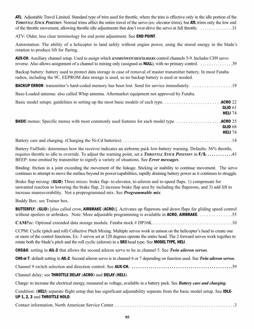
ATL: Adjustable Travel Limited. Standard type of trim used for throttle, where the trim is effective only in the idle portion of theTHROTTLE STICK POSITION. Normal trims affect the entire travel of the servo (ex: elevator trims), but ATL trims only the low endof the throttle movement, allowing throttle idle adjustments that don’t over-drive the servo at full throttle. . . . . . . . . . . . . . . .31
ATV: Older, less clear terminology for end point adjustment. See END POINT.
Autorotation: The ability of a helicopter to land safely without engine power, using the stored energy in the blade’srotation to produce lift for flaring.
AUX-CH: Auxiliary channel setup. Used to assign which KNOBS/SWITCHES/SLIDERS control channels 5-9. Includes CH9 servoreverse. Also allows assignment of a channel to mixing only (assigned as NULL), with no primary control. . . . . . . . . . . . . . . .39
Backup battery: battery used to protect data storage in case of removal of master transmitter battery. In most Futabaradios, including the 9C, EEPROM data storage is used, so no backup battery is used or needed.
BACKUP ERROR: transmitter’s hard-coded memory has been lost. Send for service immediately. . . . . . . . . . . . . . . . . .19
Base-Loaded antenna: also called Whip antenna. Aftermarket equipment not approved by Futaba.
Basic model setups: guidelines to setting up the most basic models of each type. . . . . . . . . . . . . . . . . . . . . . . . .ACRO 22GLID 61HELI 74
BASIC menus: Specific menus with most commonly used features for each model type. . . . . . . . . . . . . . . . . . . .ACRO 25GLID 68HELI 74
Battery care and charging. (Charging the Ni-Cd batteries) . . . . . . . . . . . . . . . . . . . . . . . . . . . . . . . . . . . . . . . . . . . . . .14
Battery FailSafe: determines how the receiver indicates an airborne pack low-battery warning. Defaults: 56% throttle,requires throttle to idle to override. To adjust the warning point, set a THROTTLE STICK POSITION in F/S. . . . . . . . . . . . .43BEEP: tone emitted by transmitter to signify a variety of situations. See Error messages.
Binding: friction in a joint exceeding the movement of the linkage. Sticking or inability to continue movement. The servocontinues to attempt to move the surface beyond its power/capabilities, rapidly draining battery power as it continues to struggle.
Brake flap mixing: (GLID) Three mixes: brake flap- to-elevator, to-aileron and to-speed flaps. 1) compensate forunwanted reaction to lowering the brake flap, 2) increase brake flap area by including the flaperons, and 3) add lift toincrease maneuverability. Not a preprogrammed mix. See Programmable mix.
Buddy Box: see Trainer box.
BUTTERFLY: (GLID) [also called crow, AIRBRAKE (ACRO)]. Activates up flaperons and down flaps for gliding speed controlwithout spoilers or airbrakes. Note: More adjustable programming is available in ACRO, AIRBRAKE. . . . . . . . . . . . . . .55
CAMPac: Optional extended data storage module. Futaba stock # DP16K. . . . . . . . . . . . . . . . . . . . . . . . . . . . . . . . . .10
CCPM: Cyclic (pitch and roll) Collective Pitch Mixing. Multiple servos work in unison on the helicopter’s head to create oneor more of the control functions. Ex: 3 servos set at 120 degrees operate the entire head. The 2 forward servos work together torotate both the blade’s pitch and the roll cyclic (aileron) in a SR3 head type. See MODEL TYPE, HELI.
CH5&6: setting in AIL-2 that allows the second aileron servo to be in channel 5. See Twin aileron servos.
CH6 or 7: default setting in AIL-2. Second aileron servo is in channel 6 or 7 depending on function used. See Twin aileron servos.
Channel 9 switch selection and direction control: See AUX-CH. . . . . . . . . . . . . . . . . . . . . . . . . . . . . . . . . . . . . . . . . . . . . . . . .39
Channel delay: see THROTTLE DELAY (ACRO) and DELAY (HELI).
Charge: to increase the electrical energy, measured as voltage, available in a battery pack. See Battery care and charging.
Condition: (HELI) separate flight setup that has significant adjustability separate from the basic model setup. See IDLE-UP 1, 2, 3 and THROTTLE HOLD.
Contact information, North American Service Center. . . . . . . . . . . . . . . . . . . . . . . . . . . . . . . . . . . . . . . . . . . . . . . . . . .3
95
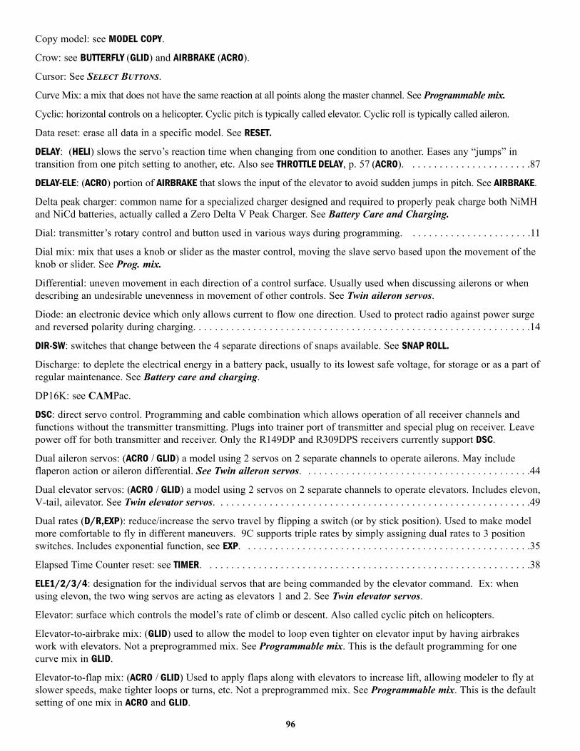
Copy model: see MODEL COPY.
Crow: see BUTTERFLY (GLID) and AIRBRAKE (ACRO).
Cursor: See SELECT BUTTONS.
Curve Mix: a mix that does not have the same reaction at all points along the master channel. See Programmable mix.
Cyclic: horizontal controls on a helicopter. Cyclic pitch is typically called elevator. Cyclic roll is typically called aileron.
Data reset: erase all data in a specific model. See RESET.
DELAY: (HELI) slows the servo’s reaction time when changing from one condition to another. Eases any “jumps” intransition from one pitch setting to another, etc. Also see THROTTLE DELAY, p. 57 (ACRO). . . . . . . . . . . . . . . . . . . . . . .87
DELAY-ELE: (ACRO) portion of AIRBRAKE that slows the input of the elevator to avoid sudden jumps in pitch. See AIRBRAKE.
Delta peak charger: common name for a specialized charger designed and required to properly peak charge both NiMHand NiCd batteries, actually called a Zero Delta V Peak Charger. See Battery Care and Charging.
Dial: transmitter’s rotary control and button used in various ways during programming. . . . . . . . . . . . . . . . . . . . . . .11
Dial mix: mix that uses a knob or slider as the master control, moving the slave servo based upon the movement of theknob or slider. See Prog. mix.
Differential: uneven movement in each direction of a control surface. Usually used when discussing ailerons or whendescribing an undesirable unevenness in movement of other controls. See Twin aileron servos.
Diode: an electronic device which only allows current to flow one direction. Used to protect radio against power surgeand reversed polarity during charging. . . . . . . . . . . . . . . . . . . . . . . . . . . . . . . . . . . . . . . . . . . . . . . . . . . . . . . . . . . . . .14
DIR-SW: switches that change between the 4 separate directions of snaps available. See SNAP ROLL.
Discharge: to deplete the electrical energy in a battery pack, usually to its lowest safe voltage, for storage or as a part ofregular maintenance. See Battery care and charging.
DP16K: see CAMPac.
DSC: direct servo control. Programming and cable combination which allows operation of all receiver channels andfunctions without the transmitter transmitting. Plugs into trainer port of transmitter and special plug on receiver. Leavepower off for both transmitter and receiver. Only the R149DP and R309DPS receivers currently support DSC.
Dual aileron servos: (ACRO / GLID) a model using 2 servos on 2 separate channels to operate ailerons. May includeflaperon action or aileron differential. See Twin aileron servos. . . . . . . . . . . . . . . . . . . . . . . . . . . . . . . . . . . . . . . . . .44
Dual elevator servos: (ACRO / GLID) a model using 2 servos on 2 separate channels to operate elevators. Includes elevon,V-tail, ailevator. See Twin elevator servos. . . . . . . . . . . . . . . . . . . . . . . . . . . . . . . . . . . . . . . . . . . . . . . . . . . . . . . . . .49
Dual rates (D/R,EXP): reduce/increase the servo travel by flipping a switch (or by stick position). Used to make modelmore comfortable to fly in different maneuvers. 9C supports triple rates by simply assigning dual rates to 3 positionswitches. Includes exponential function, see EXP. . . . . . . . . . . . . . . . . . . . . . . . . . . . . . . . . . . . . . . . . . . . . . . . . . . . .35
Elapsed Time Counter reset: see TIMER. . . . . . . . . . . . . . . . . . . . . . . . . . . . . . . . . . . . . . . . . . . . . . . . . . . . . . . . . . . .38
ELE1/2/3/4: designation for the individual servos that are being commanded by the elevator command. Ex: whenusing elevon, the two wing servos are acting as elevators 1 and 2. See Twin elevator servos.
Elevator: surface which controls the model’s rate of climb or descent. Also called cyclic pitch on helicopters.
Elevator-to-airbrake mix: (GLID) used to allow the model to loop even tighter on elevator input by having airbrakeswork with elevators. Not a preprogrammed mix. See Programmable mix. This is the default programming for onecurve mix in GLID.
Elevator-to-flap mix: (ACRO / GLID) Used to apply flaps along with elevators to increase lift, allowing modeler to fly atslower speeds, make tighter loops or turns, etc. Not a preprogrammed mix. See Programmable mix. This is the defaultsetting of one mix in ACRO and GLID.
96

Elevator-to-pitch mix: (HELI) used to adjust pitch to counter the loss of angle of attack when elevator input is given. Nota preprogrammed mix. See Programmable mix. This is the default setting of one mix in HELI.
ELEVON: flying wing configuration with 2 servos working together to create both aileron and elevator action. See Twinelevator servos. . . . . . . . . . . . . . . . . . . . . . . . . . . . . . . . . . . . . . . . . . . . . . . . . . . . . . . . . . . . . . . . . . . . . . . . . . . . . . .48
Elevons: two surfaces, one on each wing, which work as both ailerons and elevators. See ELEVON.
END BUTTON: control button used during programming to return to previous menu or close menu altogether.
END POINT: often abbreviated EPA. Adjusts the total travel in each direction of proportional servos regardless of their controlassignment. Ex: adjustment to AIL channel will adjust only the servo plugged into channel 1 even if being used as one of twoflaperons or elevons. Note: End point is not an absolute; mixing can still drive the servo farther than this setting. . . . . . . . . . .32
Engine cut: see THR-CUT.
EPA: see END POINT.
Error messages: warnings/cautions provided by the radio when potential problems may exist. . . . . . . . . . . . . . . . . . .19
Exponential (D/R,EXP): adjustment to the relationship of STICK MOVEMENT to servo movement, typically used to softenoverly sensitive models around center. . . . . . . . . . . . . . . . . . . . . . . . . . . . . . . . . . . . . . . . . . . . . . . . . . . . . . . . . . . . .35
FailSafe (F/S): sets servo positions when interference is encountered or signal is lost. Available only in PCMtransmission mode. Also includes Battery FailSafe settings. . . . . . . . . . . . . . . . . . . . . . . . . . . . . . . . . . . . . . . . . . . . .43
FLAP1/2/3/4: designation for the individual servos that are being commanded by the flap commands. Ex: when acting asflaperons, the two aileron servos are ailerons 1 and 2 and also flaps 1 and 2 (unless you set their values to 0, then they moveonly as aileron no matter what flap commands are given). See Twin aileron servos and Twin elevator servos.
Flap-to-aileron mix: (ACRO / GLID) used to create full span flap reaction in flight. Not a preprogrammed mix. SeeProgrammable mix. This is the default setup of one mix in GLID.
Flap-to-elevator mix: (ACRO / GLID) used to counteract unwanted changes in pitch when flaps are deployed. Not apreprogrammed mix. See Programmable mix. This is the default setup of one mix in ACRO and GLID.
FLAPERON: one servo on each aileron, plugged into channels 1 and 6, which operate both as ailerons and as flaps. SeeTwin aileron servos. . . . . . . . . . . . . . . . . . . . . . . . . . . . . . . . . . . . . . . . . . . . . . . . . . . . . . . . . . . . . . . . . . . . . . . . . . .44
FLAP-TRIM: Adjustment of central position of flaperons, default assigned to CHANNEL 6 KNOB. May also be used asprimary or only control of flaperons acting as flaps, or other mixes may be set up. See Twin aileron servos. . . . . . . .46
Frequency: channel on which radio transmits. . . . . . . . . . . . . . . . . . . . . . . . . . . . . . . . . . . . . . . . . . . . . . . . . . . . . . .17
Frequency band: In the entire spectrum, transmissions are designated in terms of “frequency bands” which exhibit similarproperties. In the US, specific frequencies within the 72MHz band are regulated by the FCC to be used solely for remotecontrol aircraft. 50MHz band is available for model use by those holding a HAM amateur radio operator’s license. 75MHzis solely for remote control ground models. 27MHz is legal for air or ground use. To change bands on the 9C, simplypurchase and install a module on the proper band. Receiver band MUST be changed by a service center. . . . . . . . . . . . .17
Fuel mixture control: (ACRO / HELI) see THROTTLE-NEEDLE.
FUNC: function mode of TRAINER, allows student radio to use the computer programming for that channel in the master radio.Ex: allows a student with a 4-channel transmitter to fly an 8-servo aerobatic plane or a 5-servo helicopter. See TRAINER.
Gain: the responsiveness or amount of control given the gyro. On a high gain, the gyro is very active and overridesnearly all other actions. Too high a gain may result in “wagging” at the surface as the gyro over-corrects repeatedly ineach direction. See GYRO SENS.
Gear doors: covers for retractable landing gear, may be operated separately from landing gear on some models. . . . .64
GLID: model type, glider. . . . . . . . . . . . . . . . . . . . . . . . . . . . . . . . . . . . . . . . . . . . . . . . . . . . . . . . . . . . . . . . . . . . . . . .68
Governor: electronic device that reads the speed at which the head is spinning, and adjusts the throttle servo to maintainthe desired speed.
97
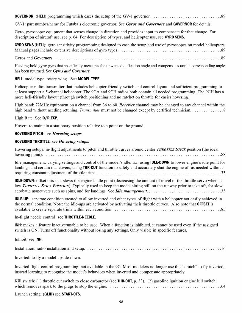
GOVERNOR: (HELI) programming which eases the setup of the GV-1 governor. . . . . . . . . . . . . . . . . . . . . . . . . . . . . . .89
GV-1: part number/name for Futaba’s electronic governor. See Gyros and Governors and GOVERNOR for details.
Gyro, gyroscope: equipment that senses change in direction and provides input to compensate for that change. Fordescription of aircraft use, see p. 64. For description of types, and helicopter use, see GYRO SENS.
GYRO SENS (HELI): gyro sensitivity programming designed to ease the setup and use of gyroscopes on model helicopters.Manual pages include extensive descriptions of gyro types. . . . . . . . . . . . . . . . . . . . . . . . . . . . . . . . . . . . . . . . . . . . .89
Gyros and Governors . . . . . . . . . . . . . . . . . . . . . . . . . . . . . . . . . . . . . . . . . . . . . . . . . . . . . . . . . . . . . . . . . . . . . . . . .89
Heading-hold gyro: gyro that specifically measures the unwanted deflection angle and compensates until a corresponding anglehas been returned. See Gyros and Governors.
HELI: model type, rotary wing. See MODEL TYPE.
Helicopter radio: transmitter that includes helicopter-friendly switch and control layout and sufficient programming toat least support a 5-channel helicopter. The 9CA and 9CH radios both contain all needed programming. The 9CH has amore heli-friendly layout (through switch positioning and no ratchet on throttle for easier hovering)
High band: 72MHz equipment on a channel from 36 to 60. Receiver channel may be changed to any channel within thehigh band without needing retuning. Transmitter must not be changed except by certified technician. . . . . . . . . . . . . .8
High Rate: See D/R,EXP.
Hover: to maintain a stationary position relative to a point on the ground.
HOVERING PITCH: see Hovering setups.
HOVERING THROTTLE: see Hovering setups.
Hovering setups: in-flight adjustments to pitch and throttle curves around center THROTTLE STICK position (the idealhovering point). . . . . . . . . . . . . . . . . . . . . . . . . . . . . . . . . . . . . . . . . . . . . . . . . . . . . . . . . . . . . . . . . . . . . . . . . . . . . .88
Idle management: varying settings and control of the model’s idle. Ex: using IDLE-DOWN to lower engine’s idle point forlandings and certain maneuvers; using THR-CUT function to safely and accurately shut the engine off as needed withoutrequiring constant adjustment of throttle trims. . . . . . . . . . . . . . . . . . . . . . . . . . . . . . . . . . . . . . . . . . . . . . . . . . . . . .33
IDLE-DOWN: offset mix that slows the engine’s idle point (decreasing the amount of travel of the throttle servo when atlow THROTTLE STICK POSITION). Typically used to keep the model sitting still on the runway prior to take off, for slowaerobatic maneuvers such as spins, and for landings. See Idle management. . . . . . . . . . . . . . . . . . . . . . . . . . . . . . . . .33
IDLE-UP: separate condition created to allow inverted and other types of flight with a helicopter not easily achieved inthe normal condition. Note: the idle-ups are activated by activating their throttle curves. Also note that OFFSET isavailable to create separate trims within each condition. . . . . . . . . . . . . . . . . . . . . . . . . . . . . . . . . . . . . . . . . . . . . . . .85
In-flight needle control: see THROTTLE-NEEDLE.
INH: makes a feature inactive/unable to be used. When a function is inhibited, it cannot be used even if the assignedswitch is ON. Turns off functionality without losing any settings. Only visible in specific features.
Inhibit: see INH.
Installation: radio installation and setup. . . . . . . . . . . . . . . . . . . . . . . . . . . . . . . . . . . . . . . . . . . . . . . . . . . . . . . . . . . .16
Inverted: to fly a model upside-down.
Inverted flight control programming: not available in the 9C. Most modelers no longer use this “crutch” to fly inverted,instead learning to recognize the model’s behaviors when inverted and compensate appropriately.
Kill switch: (1) throttle cut switch to close carburetor (see THR-CUT, p. 33). (2) gasoline ignition engine kill switchwhich removes spark to the plugs to stop the engine. . . . . . . . . . . . . . . . . . . . . . . . . . . . . . . . . . . . . . . . . . . . . . . . . .64
Launch setting: (GLID) see START-OFS.
98

Linear Mix: a mix that maintains the same relationship of master to slave throughout the whole range. Ex: a mix fromone flap servo to another flap servo at 100% causes the 2nd servo to follow the first servo’s movement exactly throughall points of travel. See Programmable mix.
LINK: mixing function that allows multiple mixes to work in conjunction. See Programmable mix.
Lithium battery: see Backup battery.
Linear: linear, directly proportional. See AIRBRAKE.
Low Band: 72MHz equipment on a channel from 11 to 35. Receiver channel may be changed to any channel within thelow band without needing retuning. . . . . . . . . . . . . . . . . . . . . . . . . . . . . . . . . . . . . . . . . . . . . . . . . . . . . . . . . . . . . . . .8
LOW BATTERY warning: transmitter’s battery is below a safe flight voltage. Recharge immediately. See Error messages.
Low rate: see D/R, EXP.
MANUAL: controlled by a switch. Ex: see AIRBRAKE.
Master: the primary control. See Programmable mix.
Mechanical gyro: uses a mechanical gyroscope (like a child’s toy gyro) to sense change of angle. See Gyros andGovernors.
MEMORY MODULE INITIALIZE: warning to indicate that the CAMPac installed in the port is not yet formatted or formattedfor a different model of transmitter. Pressing the MODE BUTTON initializes the CAMPac, deleting any existing data andformatting the CAMPac for use in the 9C. See Error codes.
MHz: Megahertz. Unit used to express frequency. 72MHz channels are aircraft only frequencies; 75MHz are ground modelonly frequencies; 27MHz are air and ground both. 50MHz is legal for HAM amateur license holders. See Frequency.
Mix, mixing rate, mix offset, mix links: See Programmable mix.
MIXER ALERT warning: notifies user that a mix is activated which is not considered desirable for engine startup. SeeError messages.
Mode: definition of which channels are assigned to which STICK movements. All 9C radios shipped in the US are Mode2, with elevator and aileron on the right STICK. To change mode, please visit www.futaba-rc.com.
MODE/PAGE BUTTON: control button on radio’s face used in various parts of programming. . . . . . . . . . . . . . . . . . . . . .11
MODEL COPY: used to duplicate the settings of one model already in memory into a second model memory. Often usedto set up 2 similar models, or make a copy of a working model to experiment with new setups. Also used to copymodels to/from the CAMpac data storage unit. . . . . . . . . . . . . . . . . . . . . . . . . . . . . . . . . . . . . . . . . . . . . . . . . . . . . .26
MODEL NAME: gives each model memory an 8-character name for easy recognition. In MODEL submenu. . . . . . . . . . .27
MODEL RESET: restore all data in a single model memory to defaults, including name and model type. See RESET.
MODEL SELECT: choose the model memory you wish to modify or fly. In MODEL submenu. . . . . . . . . . . . . . . . . . . . . .25
MODEL SELECTION ERROR: the memory last loaded in the transmitter is not currently available (usually because it is on aCAMPac not currently in the transmitter). See Error messages.
MODEL TYPE: select the type of model the aircraft is, including airplane, 2 glider types, and 5 heli types. . . . . . . . . . . .28
MODUL: modulation, means of transmitting data (PPM, PCM). In PARAMETER submenu. . . . . . . . . . . . . . . . . . . . . . . .31
Module: electronic component which can easily be removed/replaced into the transmitter, which houses all transmissioncomponents. Transmission frequency can be safely, legally and easily changed (including from band to band) bychanging the module. TP-FM is the standard module, available on any 50MHz or 72MHz frequency. You may alsopurchase TJ75FM for ground use, 75MHz. . . . . . . . . . . . . . . . . . . . . . . . . . . . . . . . . . . . . . . . . . . . . . . . . . . . . . . . . . .9
Name: see MODEL NAME.
Neckstrap: optional strap to suspend transmitter during use. Futaba stock # FTA8. See Accessories.
99
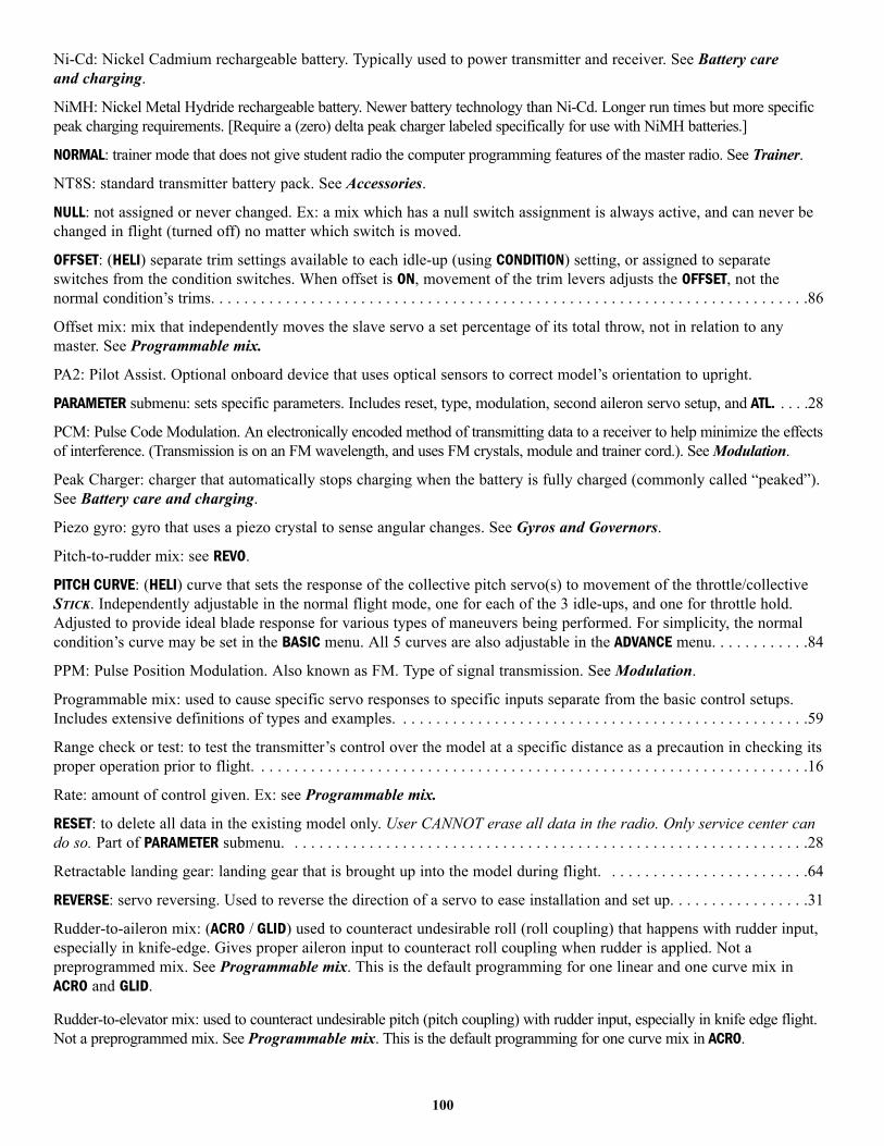
Ni-Cd: Nickel Cadmium rechargeable battery. Typically used to power transmitter and receiver. See Battery care and charging.
NiMH: Nickel Metal Hydride rechargeable battery. Newer battery technology than Ni-Cd. Longer run times but more specificpeak charging requirements. [Require a (zero) delta peak charger labeled specifically for use with NiMH batteries.]
NORMAL: trainer mode that does not give student radio the computer programming features of the master radio. See Trainer.
NT8S: standard transmitter battery pack. See Accessories.
NULL: not assigned or never changed. Ex: a mix which has a null switch assignment is always active, and can never bechanged in flight (turned off) no matter which switch is moved.
OFFSET: (HELI) separate trim settings available to each idle-up (using CONDITION) setting, or assigned to separateswitches from the condition switches. When offset is ON, movement of the trim levers adjusts the OFFSET, not thenormal condition’s trims. . . . . . . . . . . . . . . . . . . . . . . . . . . . . . . . . . . . . . . . . . . . . . . . . . . . . . . . . . . . . . . . . . . . . . . .86
Offset mix: mix that independently moves the slave servo a set percentage of its total throw, not in relation to anymaster. See Programmable mix.
PA2: Pilot Assist. Optional onboard device that uses optical sensors to correct model’s orientation to upright.
PARAMETER submenu: sets specific parameters. Includes reset, type, modulation, second aileron servo setup, and ATL. . . . .28
PCM: Pulse Code Modulation. An electronically encoded method of transmitting data to a receiver to help minimize the effectsof interference. (Transmission is on an FM wavelength, and uses FM crystals, module and trainer cord.). See Modulation.
Peak Charger: charger that automatically stops charging when the battery is fully charged (commonly called “peaked”).See Battery care and charging.
Piezo gyro: gyro that uses a piezo crystal to sense angular changes. See Gyros and Governors.
Pitch-to-rudder mix: see REVO.
PITCH CURVE: (HELI) curve that sets the response of the collective pitch servo(s) to movement of the throttle/collectiveSTICK. Independently adjustable in the normal flight mode, one for each of the 3 idle-ups, and one for throttle hold.Adjusted to provide ideal blade response for various types of maneuvers being performed. For simplicity, the normalcondition’s curve may be set in the BASIC menu. All 5 curves are also adjustable in the ADVANCE menu. . . . . . . . . . . .84
PPM: Pulse Position Modulation. Also known as FM. Type of signal transmission. See Modulation.
Programmable mix: used to cause specific servo responses to specific inputs separate from the basic control setups.Includes extensive definitions of types and examples. . . . . . . . . . . . . . . . . . . . . . . . . . . . . . . . . . . . . . . . . . . . . . . . . .59
Range check or test: to test the transmitter’s control over the model at a specific distance as a precaution in checking itsproper operation prior to flight. . . . . . . . . . . . . . . . . . . . . . . . . . . . . . . . . . . . . . . . . . . . . . . . . . . . . . . . . . . . . . . . . . .16
Rate: amount of control given. Ex: see Programmable mix.
RESET: to delete all data in the existing model only. User CANNOT erase all data in the radio. Only service center cando so. Part of PARAMETER submenu. . . . . . . . . . . . . . . . . . . . . . . . . . . . . . . . . . . . . . . . . . . . . . . . . . . . . . . . . . . . . . .28
Retractable landing gear: landing gear that is brought up into the model during flight. . . . . . . . . . . . . . . . . . . . . . . . .64
REVERSE: servo reversing. Used to reverse the direction of a servo to ease installation and set up. . . . . . . . . . . . . . . . .31
Rudder-to-aileron mix: (ACRO / GLID) used to counteract undesirable roll (roll coupling) that happens with rudder input,especially in knife-edge. Gives proper aileron input to counteract roll coupling when rudder is applied. Not apreprogrammed mix. See Programmable mix. This is the default programming for one linear and one curve mix inACRO and GLID.
Rudder-to-elevator mix: used to counteract undesirable pitch (pitch coupling) with rudder input, especially in knife edge flight.Not a preprogrammed mix. See Programmable mix. This is the default programming for one curve mix in ACRO.
100
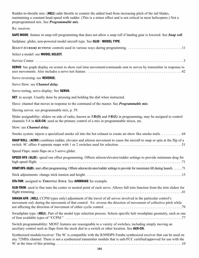
Rudder-to-throttle mix: (HELI) adds throttle to counter the added load from increasing pitch of the tail blades,maintaining a constant head-speed with rudder. (This is a minor effect and is not critical in most helicopters.) Not apreprogrammed mix. See Programmable mix.
Rx: receiver.
SAFE MODE: feature in snap roll programming that does not allow a snap roll if landing gear is lowered. See Snap roll.
Sailplane: glider, non-powered model aircraft type. See GLID / MODEL TYPE.
SELECT (CURSOR) BUTTONS: controls used in various ways during programming. . . . . . . . . . . . . . . . . . . . . . . . . . . . . .11
Select a model: see MODEL SELECT.
Service Center. . . . . . . . . . . . . . . . . . . . . . . . . . . . . . . . . . . . . . . . . . . . . . . . . . . . . . . . . . . . . . . . . . . . . . . . . . . . . . . .3
SERVO: bar graph display on screen to show real time movement/commands sent to servos by transmitter in response touser movements. Also includes a servo test feature. . . . . . . . . . . . . . . . . . . . . . . . . . . . . . . . . . . . . . . . . . . . . . . . . . .42
Servo reversing: see REVERSE.
Servo Slow: see Channel delay.
Servo testing, servo display: See SERVO.
SET: to accept. Usually done by pressing and holding the dial when instructed.
Slave: channel that moves in response to the command of the master. See Programmable mix.
Slaving servos: see programmable mix, p. 59.
Slider assignability: sliders on side of radio, known as VR(D) and VR(E) in programming, may be assigned to controlchannels 5-8 in AUX-CH, used as the primary control of a mix in programmable mixes, etc.
Slow: see Channel delay.
Smoke system: injects a specialized smoke oil into the hot exhaust to create air-show like smoke trails. . . . . . . . . . . .64
SNAP ROLL: (ACRO) combines rudder, elevator and aileron movement to cause the aircraft to snap or spin at the flip of aswitch. 9C offers 4 separate snaps with 1 or 2 switches used for selection. . . . . . . . . . . . . . . . . . . . . . . . . . . . . . . . . .51
Speed Flaps: main flaps on a 5-servo glider.
SPEED OFS (GLID): speed run offset programming. Offsets aileron/elevator/rudder settings to provide minimum drag forhigh speed flight. . . . . . . . . . . . . . . . . . . . . . . . . . . . . . . . . . . . . . . . . . . . . . . . . . . . . . . . . . . . . . . . . . . . . . . . . . . . .71
START OFS (GLID): start offset programming. Offsets aileron/elevator/rudder settings to provide for maximum lift during launch. . . . . . .71
Stick adjustments: change stick tension and height. . . . . . . . . . . . . . . . . . . . . . . . . . . . . . . . . . . . . . . . . . . . . . . . . . . .15
STk-THR: assigned to THROTTLE STICK. See AIRBRAKE for example.
SUB-TRIM: used to fine tune the center or neutral point of each servo. Allows full trim function from the trim sliders forflight trimming. . . . . . . . . . . . . . . . . . . . . . . . . . . . . . . . . . . . . . . . . . . . . . . . . . . . . . . . . . . . . . . . . . . . . . . . . . . . . . .41
SWASH AFR: (HELI, CCPM types only) adjustment of the travel of all servos involved in the particular control’smovement only during the movement of that control. Ex: reverse the direction of movement of collective pitch whilenot affecting the direction of movement of either cyclic control. . . . . . . . . . . . . . . . . . . . . . . . . . . . . . . . . . . . . . . . . .79
Swashplate type: (HELI). Part of the model type selection process. Selects specific heli swashplate geometry, such as oneof four available types of “CCPM.” . . . . . . . . . . . . . . . . . . . . . . . . . . . . . . . . . . . . . . . . . . . . . . . . . . . . . . . . . . . . . .77
Switch programmability: MOST features are reassignable to a variety of switches, including simply moving anauxiliary control such as flaps from the stock dial to a switch or other location. See AUX-CH.
Synthesized module/receiver: The 9C is compatible with the R309DPS Futaba synthesized receiver that can be used onany 72MHz channel. There is not a synthesized transmitter module that is safe/FCC certified/approved for use with the9C at the time of this printing. . . . . . . . . . . . . . . . . . . . . . . . . . . . . . . . . . . . . . . . . . . . . . . . . . . . . . . . . . . . . . . . . . . .10
101
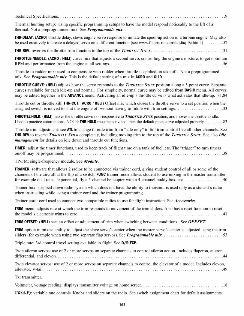
Technical Specifications. . . . . . . . . . . . . . . . . . . . . . . . . . . . . . . . . . . . . . . . . . . . . . . . . . . . . . . . . . . . . . . . . . . . . . . . .9
Thermal hunting setup: using specific programming setups to have the model respond noticeably to the lift of athermal. Not a preprogrammed mix. See Programmable mix.
THR-DELAY: (ACRO) throttle delay, slows engine servo response to imitate the spool-up action of a turbine engine. May alsobe used creatively to create a delayed servo on a different function (see www.futaba-rc.com\faq\faq-9c.html.) . . . . . . . .57
THR-REV: reverses the throttle trim function to the top of the THROTTLE STICK. . . . . . . . . . . . . . . . . . . . . . . . . . . . . . .31
THROTTLE-NEEDLE: (ACRO / HELI) curve mix that adjusts a second servo, controlling the engine’s mixture, to get optimumRPM and performance from the engine at all settings. . . . . . . . . . . . . . . . . . . . . . . . . . . . . . . . . . . . . . . . . . . . . . . . . .56
Throttle-to-rudder mix: used to compensate with rudder when throttle is applied on take off. Not a preprogrammedmix. See Programmable mix. This is the default setting of a mix in ACRO and GLID.
THROTTLE CURVE: (HELI) adjusts how the servo responds to the THROTTLE STICK position along a 5 point curve. Separatecurves available for each idle-up and normal. For simplicity, normal curve may be edited from BASIC menu. All curvesmay be edited together in the ADVANCE menu. Activating an idle-up’s throttle curve is what activates that idle-up. .81,84
Throttle cut or throttle kill: THR-CUT. (ACRO / HELI) Offset mix which closes the throttle servo to a set position when theassigned switch is moved to shut the engine off without having to fiddle with trim settings. . . . . . . . . . . . . . . . . . . . .33
THROTTLE HOLD: (HELI) makes the throttle servo non-responsive to THROTTLE STICK position, and moves the throttle to idle.Used to practice autorotations. NOTE: THR-HOLD must be activated, then the default pitch curve adjusted properly. . . . . . . . .83
Throttle trim adjustment: see ATL to change throttle trim from “idle only” to full trim control like all other channels. SeeTHR-REV to reverse THROTTLE STICK completely, including moving trim to the top of the THROTTLE STICK. See also Idlemanagement for details on idle down and throttle cut functions.
TIMER: adjust the timer functions, used to keep track of flight time on a tank of fuel, etc. The “trigger” to turn timerson/off may be programmed. . . . . . . . . . . . . . . . . . . . . . . . . . . . . . . . . . . . . . . . . . . . . . . . . . . . . . . . . . . . . . . . . . . . .38
TP-FM: single-frequency module. See Module.
TRAINER: software that allows 2 radios to be connected via trainer cord, giving student control of all or some of thechannels of the aircraft at the flip of a switch. FUNC trainer mode allows student to use mixing in the master transmitter,for example dual rates, exponential, fly a 5-channel helicopter with a 4-channel buddy box, etc. . . . . . . . . . . . . . . . .40
Trainer box: stripped-down radio system which does not have the ability to transmit, is used only as a student’s radiowhen instructing while using a trainer cord and the trainer programming.
Trainer cord: cord used to connect two compatible radios to use for flight instruction. See Accessories.
TRIM menu: adjusts rate at which the trim responds to movement of the trim sliders. Also has a reset function to resetthe model’s electronic trims to zero. . . . . . . . . . . . . . . . . . . . . . . . . . . . . . . . . . . . . . . . . . . . . . . . . . . . . . . . . . . . . . .41
TRIM OFFSET: (HELI) sets an offset or adjustment of trim when switching between conditions. See OFFSET.
TRIM option in mixes: ability to adjust the slave servo’s center when the master servo’s center is adjusted using the trimsliders (for example when using two separate flap servos). See Programmable mix. . . . . . . . . . . . . . . . . . . . . . . . . . .53
Triple rate: 3rd control travel setting available in flight. See D/R,EXP.
Twin aileron servos: use of 2 or more servos on separate channels to control aileron action. Includes flaperon, ailerondifferential, and elevon. . . . . . . . . . . . . . . . . . . . . . . . . . . . . . . . . . . . . . . . . . . . . . . . . . . . . . . . . . . . . . . . . . . . . . . . .44
Twin elevator servos: use of 2 or more servos on separate channels to control the elevator of a model. Includes elevon,ailevator, V-tail. . . . . . . . . . . . . . . . . . . . . . . . . . . . . . . . . . . . . . . . . . . . . . . . . . . . . . . . . . . . . . . . . . . . . . . . . . . . . .49
Tx: transmitter.
Voltmeter, voltage reading: displays transmitter voltage on home screen. . . . . . . . . . . . . . . . . . . . . . . . . . . . . . . . . . .18
VR(A-E): variable rate controls. Knobs and sliders on the radio. See switch assignment chart for default assignments.
102

VR(A-C) are knobs; VR(D-E) are sliders on the case sides.
V-tail model Mix: (ACRO / GLID) programming used to control a V-tail model’s tail surfaces, with 2 servos operating 2control surfaces as both rudder and elevator. See Twin elevator servos.
Warning messages: cautions provided by the radio when certain potential problems exist. See Error messages.
Warranty information. . . . . . . . . . . . . . . . . . . . . . . . . . . . . . . . . . . . . . . . . . . . . . . . . . . . . . . . . . . . . . . . . . . . . . . . . . .3
Website: www.futaba-rc.com. Internet location of extensive technical information Futaba products. . . . . . . . . . . . . . . .3
Whip antenna: aftermarket, shortened antenna. Not approved by Futaba.
103


![INSTRUCTION MANUAL - Hobbicomanuals.hobbico.com/gpm/gpma1330-manual-v1_2.pdf · INSTRUCTION MANUAL Length: 60" [1,524mm] Weight: 10.25 lbs ... SAFETY PRECAUTIONS ... Dead Center ™](https://img.pdfslide.us/doc/110x75/5aafd1a47f8b9a59478dd005/instruction-manual-manual-length-60-1524mm-weight-1025-lbs-safety-precautions.jpg)