Embed Size (px)
Citation preview
1
INSTRUCTIONMANUAL
SEBRING / EATON SUPERCHARGER KIT
FOR THE MAZDA MIATA
1.6L MODELS ‘90-’93
1.6 w/ power steering and AC 999-0001.6 w/ power steering and no AC 999-0051.6 w/o power steering and no AC 999-0101.6 w/o power steering and w/ AC 999-015
Revision Date 1-98

2
DESCRIPTION OF THE SEBRING MIATA SUPERCHARGER KIT
Using a 45 cubic inch Roots-type supercharger built by Eaton Corporation, six psi ofboost is developed to pressurize the stock intake manifold of a Mazda Miata engine.The supercharger is driven by a four rib poly vee belt running on the standard Mazdacrank pulley, sharing the belt with the power steering pump and air conditioning com-pressor where applicable.
For optimum performance, the stock throttle body is relocated upstream of the super-charger. A “dummy” throttle body is used to maintain the Mazda idle control valve andassorted electronics which stay in their original position on the intake manifold. Thethrottle cable is reused but mounted on the driver’s side of the engine, as is the super-charger itself.
Gaining from the millions of dollars that Eaton has spent developing their superchargerdesign for OE installations, the efficiency and reliability of the kit are remarkable.Volumetric efficiency of the M45 supercharger used in this installation is 88%. Thermalefficiency for the installed system is 82%. Maximum heat gain at 6 psi boost is 74degrees fahrenheit. This eliminates the need for intercooling and the subsequent lossin throttle response.
A unique feature of the Eaton-built supercharger is a bypass manifold which “disen-gages” the supercharger during periods of vacuum greater than five inches of mercury.In practice, this means that the supercharger draws no load from the engine during idleand highway cruising, greatly improving driveability, engine smoothness, and fuelmileage. This bypass feature is an Eaton trademark and is used on the OE installa-tions by Ford, GM, Mercedes Benz, and Aston Martin. Every part of your kit isdesigned to the same strict standards as a factory installation.
Fuel management is controlled by a reliable pneumatic fuel pressure regulator. In non-boost conditions, the stock Mazda regulator controls the fuel rail pressure from 5 to 36psi. Once positive boost is created by the supercharger, the fuel rail pressure is raised7 psi for every 1 psi of boost to a maximum of 75 psi. No other modifications are nec-essary to the engine other than a slight retarding of the idle ignition timing to 8 degreesBefore Top Dead Center (BTDC) from 10 degrees BTDC. Gasoline of at least 93octane is required (92 octane fuel can be used with an ignition timing of 6 degreesBTDC).
The kit requires no permanent modification to the subject car.

3
Installation instructions for the SEBRING
MiataSupercharger Kit
INSTALLATION TIME: AS LITTLE AS 3 HOURS FOR EXPERIENCED MECHANICS,AROUND FIVE TO EIGHT HOURS FOR “OCCASIONAL” MECHANICS.
TOOLS REQUIRED: 3/8” Drive Socket set w/ 17mm, 14mm, 13mm, 12mm, 10mm &8mm sockets; Deep sockets (14mm or 9/16”, 10mm): Phillips and Standard screwdriv-er; 10mm, 12mm, and 17mm open end wrench; 5mm Allen wrench with a 3/8” drive;paper clip; a box to store your OLD PARTS in. Loctite 242 thread locking compound isrecommended. A 1/4” drive socket set will be useful with some of the tight workingareas. A timing light will be needed to set the ignition timing.
A NOTE ON ADDING A SUPERCHARGER TO YOUR MIATAThis kit has been carefully designed with attention to every detail utilizing over 1000hours of engineering and testing. Each component of this kit has been carefullydesigned to match the quality of the automobile you purchased from Mazda. Thesupercharger itself will last over 120,000 miles without attention. The only added main-tenance item for your Miata will be an occasional belt tension check for the super-charger drive. As for your engine’s life, a Miata engine in good condition will see littlereduction in useful life with the addition of this kit.
However, it is your responsibility to insure that your engine is in tip top shape beforeyou install this kit. Putting boost on a tired engine will lead to catastrophe. If your carhas under 80,000 miles on it and has had the oil changed regularly (every 3000 milesor so), you should have no trouble. If in doubt, check your engine’s compression. Youshould have at least 135 psi of compression in each cylinder with no more than a 10%variance between any two cylinders or with a 10% increase in any cylinder after atablespoon of oil is poured in. Your cooling system should be up to par (new coolant).Basically, if you have a good engine, it will be very happy with this supercharger.
BEFORE INSTALLING THIS KIT: A) Drive your fuel tank empty and refill with 93 octane major brand gasoline. If you canonly find 92 octane, see step #3 under “Adjustments” at the end of these instructions.
B) Change your oil and filter. Use a synthetic oil if possible (Mobil 1 or similar, seenotes at end of instructions).
C) Change your spark plugs if they have more than 10,000 miles on them. We sug-gest a set of slightly cooler plugs (#971-075) to prevent detonation. Gap these plugs at0.038 inches. Use anti-seize compound on the threads. Splitfire spark plugs are notrecommended for boosted engines due to their higher heat range.
D) Change your fuel filter if it has more than 20,000 miles on it. This is critical.

4
SUMMARY OF THE INSTALLATION
The supercharger mounts to the cylinder head via two existing tapped holes on theexhaust manifold side. The forward hole is used by Mazda for the forward enginepulling eyelet. Underneath the supercharger, a straight strap bracket attaches to thepower steering mounting bolt (or to the idler bracket on non-power steering vehicles). Asecond bracket is attached at the supercharger end of this strap bracket to hold therelocated throttle cable which acts on the stock throttle body, which has been movedupstream of the supercharger. A dummy throttle body is attached to the intake manifoldto maintain the idle air control valve functions. The airflow meter is relocated to justinside the driver side shock tower and is connected to the supercharger/throttle bodyassembly via a cast aluminum elbow which has two air port nipples for idle air andcrankcase ventilation hoses. The fuel return line leaving the Mazda pressure regulatoris interrupted by an Auxiliary Fuel Pressure Regulator (AFPR) which receives a vacu-um/boost signal via a signal line attached to the intake manifold.
Easiest portions of the installation:Auxiliary Fuel Pressure RegulatorSupercharger mountingThrottle Body relocation
More difficult portions of the installationAir flow meter to supercharger elbow installationAir filter installation

BEGINNING THE INSTALLATION
1.0 DISASSEMBLY
1.1 With the engine running, raise the hood and locate the main underhood fuse boxby the fenderwell near the firewall on the passenger side of the engine compartment.Lift the main fuse box cover and locate the relay labeled “FUEL INJ”. While the engineis running, remove the “FUEL INJ” relay. The engine will stop running. Turn your igni-tion key off. Store the “FUEL INJ” relay in a safe place until you are finished with theinstallation.
Release the pressure in your fuel tank by removing your gas capmomentarily.
1.2 Release the airflow meter harness 7 pin connector by lifting the small wire clip thatruns around the rectangular base of the connector. Remove the stock air flow meter,air filter box and intake snorkel. Remove the air flow meter from the air box. Store theair box, filter, and snorkel away. Move the air flow meter to a safe place on a worktable.
5
FIGURE 1.1

1.0 DISASSEMBLY (continued)1.3 Remove the molded rubber elbow and hard plastic tube that lead from the throttlebody to the airflow meter. If you have cruise control, you will also have to remove thevacuum line from the intake manifold nipple and from the points where it attaches tothe hard plastic intake tube. Remove the cruise control vacuum line from the cruiseactuator as well and save it for use in step #4.5 below.
1.4 Remove the chrome crankcase vent pipe that is attached to the front of the camcover and the rubber hose that leads into the cam cover (Figure 1.4). These can bestored away.
Also, find the small restrictor inside the rubber hose that ran from the cam cover to thechrome tubing. It can be felt as a lump in the straight section of the hose near thechrome tube end. Persuade it out by gently clamping the hose with a pair of pliers justbehind the “lump”. Save this restrictor for step #7.8. Re-install the chrome bolts thatheld the tubing in place. Store the chrome tube and Mazda hoses away.
6
FIGURE 1.4

1.5 Locate the new engine thermostat from your supercharger kit. Installing the ther-mostat is as easy as it looks - it is right there on the front of the engine where the topradiator hose goes into the thermostat housing cap. Remove the two bolts holding thecover and gently lift it off. You can leave the radiator hose attached to the cover. Placeyour new thermostat (spring end down) into the thermostat base. Reinstall the coverwith a new gasket (provided). Make sure the old gasket material is completely off ofboth mating surfaces. Remember to remove the new thermostat gasket’s white protec-tive paper to expose an adhesive layer to assist in assembly.
You can do this entire procedure without losing too much coolant, there is no need todrain your cooling system. Simply place some old newspapers on the floor to catch thepint of coolant that will spill. Make sure to top off your coolant tank once the engine iswarm. If your coolant is over two years old, you must change it (see page 7-15 of yourowner’s manual). Your supercharged car will be using 100% of your cooling systemand it must be up to the task.
7
FIGURE 1.5

2.0 THROTTLE BODY
2.1 Remove the throttle body (FIGURE 1.4) by releasing the two electrical connectors (one hasa spring wire, one has a plastic lever clip), the two small coolant hoses on either side of thelower Idle Control System (ICS) valve, and the four bolts.
TIP: THE SPRING HOSE CLAMPS FROM MAZDA ARE BEST REMOVED BY APPROACHINGFROM THE SIDE WITH NEEDLE NOSE PLIERS. GRASP ALL THREE TANGS AT ONCE ANDCOMPRESS THEM TOGETHER. THIS IS EASIER TO DO WITH THE THROTTLE BODYALREADY LOOSE FROM THE INTAKE MANIFOLD.
Plug the coolant hoses with a screw driver, golf tee, or pencil to prevent the leakage of coolant(OR - keep the hose ends above the radiator cap level to prevent leakage). Release the throttlecable from the throttle shaft spool. Release the Throttle Position Switch harness by lifting thesmall wire clip that runs around the rectangular base of the connector.
If the throttle body gasket tears as you remove it, you will need to clean off the old gasket fromboth surfaces, the throttle body and the intake manifold. Carefully use a knife or the backside ofa hacksaw blade to scrape the mounting surfaces clean. DO NOT SCRATCH OR MAR THEMOUNTING SURFACES IN ANY WAY.
2.2 Moving to a work table, remove the idle air con-trol (ICS) valve from the bottom of the throttle bodyby removing the three Phillips head screws. Use agood quality screwdriver and be careful not to stripthe Phillips head screw. If you cannot loosen ascrew with the screwdriver, use a small set of pliersfrom the side.
Carefully separate the two units making sure not totear the rubber gland gasket. The rubber glandgasket will want to stay with the Mazda throttlebody - carefully pick it out with a flat blade screw-driver and save it for the next step.
2.3 Take the Idle Air Manifold (dummy throttlebody) from your supercharger kit and install theMazda idle air control valve (ICS) from step 2.2 in the appropriate place. Use the rubber glandgasket from the Mazda throttle body in this position. Re-use the three Mazda Phillips screws.Use no sealant, just the rubber gasket.
2.4 Install the Dummy Throttle Body and ICS valve and rubber gland gasket assembly backonto the intake manifold in the same position as the standard throttle body on the intake mani-fold. Use the new paper gasket provided. Reconnect the coolant hoses to the idle control valveas you found them.
2.5 Reconnect the idle control valve electrical connector.
2.6 Take the Throttle Position Switch (TPS) extension wire (3 conductor with sheathing) fromyour kit and use it to extend your factory TPS harness. We have provided six heat shrink buttcrimp connectors to use for each wire junction
FIGURE 2.2
8

2.0 THROTTLE BODY (continued)
You will first have to cut the three pin connector off of the end of the Mazda TPS har-ness. Cut at least 3 inches back from the end of the plastic connector to give yourselfenough room to work with. You will be splicing in the Sebring-supplied extender,matching color to color. Our extender has three color coded wires that match the col-ors of the Mazda harness. Strip a small section from each wire’s end on the Sebringextender and connect it to the appropriate color wire (red conductor to red Mazda wire,etc.). Use the heat shrink butt connectors to secure each splice. Crimp with an appro-priate tool or pliers. Use a heat gun or similar to shrink the butt connector’ s protectivetubing over the crimped connector. We do not recommend the use of open flame toshrink the tubing. Wrap the entire grouping of three connectors with electrical tape atboth ends to protect from moisture and dirt.
2.7 Locate the ICS blanking plate and take it over to your Mazda throttle body workarea. The orange rubber gasket from your kit will go between the blanking plate andthe Mazda throttle body. Install this blanking plate onto your Mazda throttle body,pinching the orange rubber blanking plate gasket. Use the three Phillips head screwssupplied in the kit.
3.0 BELT DRIVES
3.1 NOTE: CARS WITH POWER STEERING: You will be re-arranging your power steering brack-et components per figure 3.2. Referring to figure 3.1, remove the slot bracket and pil-low block by removing bolts “A”, “C”, and “D”.
9
FIGURE 3.1

10
3.0 BELT DRIVES (continued)
Take the flat idler pulley bracket from your kit and trial fit it to the assembly per figure3.2. You will be moving the pillow block and bolt “D” to behind the power steeringstamped steel bracket. This makes room for the flat idler pulley bracket. The uppersupport for the repositioned long bolt “D” comes from a relocated Mazda slot bracket. Itbecomes an extension bracket for bolt “D”. The slot bracket is attached to the stampedsteel power steering bracket using a new bolt/washer/nut assembly supplied in yourkit. Make sure to point this bolt with its head nearest the plastic idler pulley and thatthis bolt goes through the slot. The forward hole of the repositioned slot bracket will notbe used. The rearward hole is now used for the relocated “D” bolt which will be used totighten your drive belt. Note: The power steering pump must be in its lowest positionfor this procedure.
FIGURE 3.2

3.0 BELT DRIVES (continued)
3.2 When you are done with your trial fitting of the flat idler pulley bracket, take this flatbracket to a workbench and install the two plastic idler pulleys using the spacers, boltsand nyloc nuts provided. Make sure that the bolts point toward the front of the car.
3.3 Secure the idler pulleys firmly to the flat bracket. Proceed to install the idler pulleyassembly onto the car per the procedure practiced during the trial fitting.
The final assembly (minus the pulleys) should look like figure 3.3.
VERY IMPORTANT: MAKE SURE THAT THE DRIVER’S SIDE IDLER PULLEY ISFREE TO SPIN. THE PINCH BOLT THAT YOU INSTALL THROUGH THE PILLOWBLOCK FROM THE REAR CAN INTERFERE WITH THE BACKSIDE OF THE IDLERIF INSTALLED INCORRECTLY (i.e. leaving out the thick washer under the bolt’shead). TEST THE ASSEMBLY BY TIGHTENING THE PINCH BOLT FULLY AND SPIN-NING THE IDLER PULLEY. USE ADDITIONAL WASHERS UNDER THE PINCHBOLT’S HEAD IF NECESSARY.
11
FIGURE 3.3

3.0 BELT DRIVES (continued)
VERY IMPORTANT: Check the clearance between the small coolant hose that runsfrom the base of the thermostat housing and the passenger side plastic idler pulley(see figure 8.1). If the clearance is less than 1/2 inch between the hose and the pulley,trim three quarters of an inch of length off of the thermostat end of the small hose.Reinstall the hose, reusing the spring clamp. By removing a small piece of the hoseend, the hose will be pulled away from the idler pulley, avoiding any damage duringoperation. This is a critical area for attention since a hose failure could cause severeengine damage. Not all cars need this modification.
3.4 POWER STEERING CARS: Spin the power steering pump pulley until the nuton the main pump mounting bolt is visible. Insert a socket wrench (deep 14mm) hereand hold the rear hex head with a 14mm box wrench. Remove the nut and the longbolt (item “B” in figure 3.1). The bolt will retract rearward underneath the exhaust mani-fold.
12
FIGURE 3.4

3.0 BELT DRIVES (continued)
3.5 Pick the flat steel supercharger bracket from the kit and slip the long power steer-ing pump mounting bolt through the non-slotted end. Reinstall the power steeringpump bolt and nut with the flat bracket pinched between the bolt head and the castpower steering pump bracket that is on the engine.
When finished, rotate the power steering pump as far down as possible (the pulley willtouch the AC compressor pulley if so equipped). This will allow room for the super-charger to be installed and for the belt to slip over the pulleys.
3.6 NON POWER STEERING CARS: Locate your lower bracket assembly fromthe kit. The end with the small 90 degree bracket mounts to the idler bracket (standardon AC equipped cars) or to new idler bracket (supplied with kit for non-AC, non-PScars). Use the new, longer 10mm bolt provided to attach this bracket to the engine(Review figure 3.4 for bolt location).
13
FIGURE 3.5

4.0 FUEL MANAGEMENT
4.1 Locate the Mazda pressure regulator at the firewall end of the fuel injector rail.There is a short vacuum hose running to it that initiates on the top rear of the intakemanifold. Follow the fuel hosethat runs from the bottom of theMazda pressure regulator to themetal fuel pipe on the passen-ger side of the engine compart-ment, just near the intake mani-fold. It will have a white paintmark on it. This is the fuel returnhose. Remove the fuel returnhose from the metal fuel pipeattached to the chassis, beingcareful not to spill any fuel.Make sure that you havereleased the pressure in yourgas tank by removing your gascap first.
4.2 Locate your Auxiliary FuelPressure Regulator (AFPR)from the kit. Attach the twobrass hose barbs to the under-side using the teflon pipesealant tape provided. Wrap a single layer of the teflon tape around the threaded endin a clockwise direction (as viewed from the threaded end). Run both barbs down tight.
14
4.0 FUEL MANAGEMENT
4.3 Reconnect the return fuel hose from theMazda pressure regulator to the offset hosebarb on the AFPR supplied in your super-charger kit. Take the short 5/16” diameter fuelhose from the kit and connect the center hosebarb of the AFPR to the metal fuel return tubein the engine compartment (where the Mazdafuel hose was connected before). Use thehose clamps proved on all connections.IMPORTANT!: Double check that the outsidebarb goes to the Mazda pressure regulatorand the center barb goes to the metal fuelreturn tube (with the white mark) attached tothe chassis. If you hook it up wrong, you willruin some very expensive fuel injection com-ponents.
FIGURE 4.1
FIGURE 4.3

4.0 FUEL MANAGEMENT
4.4 Locate the evaporative canister just behind the passenger side headlight. TheAFPR will be bolted to the evaporative canister bracket. First, remove the plastic clampthat holds the large diameter evaporative vent tube (from the center top of the evapo-rative canister) in place on the side of the canister bracket. Hold the AFPR in placewith its threaded hole backing up to the evaporative canister support bracket.
Make sure that your return fuel hose does not become kinked during installation. Thiscan be achieved by forming a circular loop with the hose aimed downward as it leavesthe metal fuel pipe, looping up to the center barb on the AFPR.
Use the bolt provided to secure the AFPR to the evaporative canister bracket. Makesure that the evaporator vent tube is not pinched. Make very sure that the fuel linesare not pinched in any way, nor that they are chaffing against any metal at any point.
Double check that your fuel lines do not kink.
15
FIGURE 4.4

5.0 SUPERCHARGER PREPARATION
5.1 Working on a table, set the supercharger unit in a position easy to work with. Bevery careful not to bump the supercharger pulley in any way as it can easily damagethe front bearing. Check outlet manifold for debris and clean it out if necessary. Installthe outlet manifold as shown in figure 5.1.
Get your Mazda throttle body with the ICS blanking plate as installed in step #2.7 andmount it to the supercharger using the new gasket and the four bolts (8mm x 40) sup-plied in the kit.
5.0 SUPERCHARGER PREPARATION
5.2 Locate your throttle cable bracket that is bolted to your standard intake manifoldand remove the throttle cable by loosening the pinch nuts surrounding the cable endon either side of thebracket. Once the nutsare loose, you can pullthe cable out of thebracket - the grommetwill deform and let youdo this. Remove thethrottle cable bracketby removing the two10mm headed bolts.Unclip the throttlecable from the firewallanchors. Begin re-rout-ing the throttle cable bylooping the end behindthe brake master cylin-der and laying itslength along the dri-ver’s side fender well.
FIGURE 5.1
FIGURE 5.2
16

5.0 SUPERCHARGER PREPARATION
5.3 Locate the cast aluminum elbow (2.5” inside diameter) from your kit. Check elbowfor debris and clean it out if necessary. You will be placing the assembly into the posi-tion shown prior to installing the supercharger. Make sure to install the 2.5” to 2.75”reducer hose to the airflow meter end of this cast elbow prior to setting it in place. Thiswill greatly assist in airflow meter installation. Also, install the 2.5” diameter hump hoseto the throttle body end of this cast elbow. Use the clamps provided to secure the
hoses to the elbow6.0 SUPERCHARGER INSTALLATION
6.1 Remove the engine lift eyelet at the front of the engine, just above the exhaustmanifold by removing the bolt using a 14mm socket. Using the two new flanged head-ed bolts supplied with your kit, install these to the two bosses on the side of your cylin-der head. Leave at least 1/2” of thread exposed on each bolt.
6.2 Bring the supercharger over to theengine. Feed the throttle body end intothe hump hose already installed on thecast aluminum “air flow meter to throttlebody elbow” (make sure to slip a fullyopened hose clamp over the hose first).Orient the supercharger so that you canslip the large “keyholes” in the bracketattached to the supercharger over the twobolt heads installed in step #6.1. Makesure that the bolts move up their respec-tive vertical slots and seat against theupper edge of the horizontal slots in thebracket.
Slide the supercharger towards thefirewall as far as it will go. Tighten downthe two pinch bolts using an open endwrench.
If you find that the bracket/super-charger assembly collides with your cam cover vent tube during initial installation, itmeans you did not leave enough threads exposed on the two main mounting boltsinstalled in step #6.1. Retry it with the bolts further out..
FIGURE 5.3
FIGURE 6.1
17
6.0 SUPERCHARGER INSTALLATION (continued)
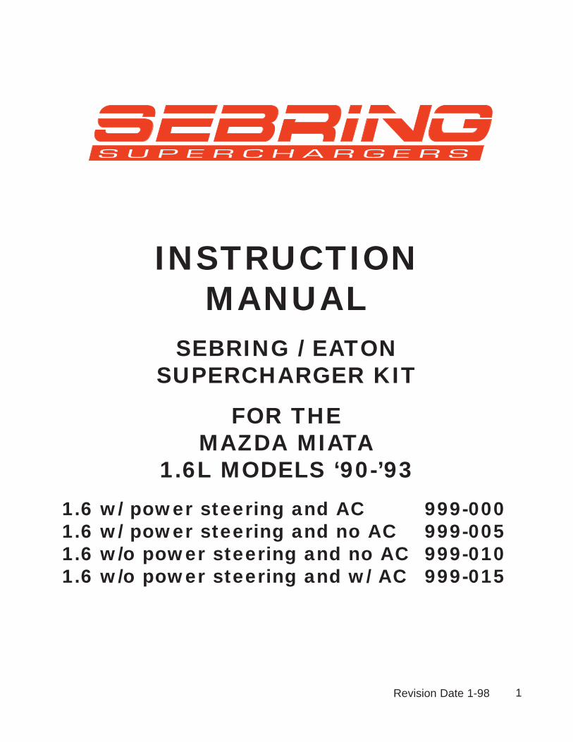
6.4 Swing the flat lower bracket up into place in front of the supercharger boss. Locatethe small stamped throttle cable bracket from your kit and thread the new bolt throughthe throttle cable bracket hole, through the supercharger boss and through the flatsteel lower bracket. Secure with the locking nut and bolt supplied. Make sure that thehead of the bolt is on the throttle bracket side of the assembly.
Leave the power steering pump long bolt and nut finger tight (14mm heads).
18
FIGURE 6.4

6.0 SUPERCHARGER INSTALLATION (continued)
6.6 Route your throttle cable so that it is looped back toward the firewall, routing thecable just behind the driver’s side headlamp motor. Install the cable’s threaded endinto the small bracket attached to the underside of the supercharger. Make certainthat the cable/grommet is fully nested within the slot (this may require some mus-cle - we made it tight so your throttle cable won’t ever fall out). Open the throttle byhand and insert the cable end into the throttle spool. Make sure that the cable runs inthe center of the groove of the throttle spool. If it does not, adjust the throttle cablebracket left or right until it is centered in the spool’s groove.
Have an assistant operate the gas pedal multiple times to confirm that the action isfree and easy without binding or interference. Make sure that the cable has a bit of“sloppy” slack with the gas pedal released and that full throttle is available when thegas pedal is fully depressed. If it does not “flop” in the idle position, you will have trou-ble setting your idle speed. Make sure that the cable is run in such a way as to allowfor engine movement from side to side.
Make very certain that all throttle cable mounting points are secure - this instal-lation area is critical for safe operation of your car. This bracketry has been care-fully designed for correct operation. It is your responsibility as the installer toensure that it is bolted together successfully without binding or interference.
6.7 Connect the 48+” long vacuum hose (supplied) to the hose barb on the super-charger’s bypass manifold. Use the horizontal hose barb that is pointed rearwardtoward the car’s firewall. Carefully tie this hose off so it neatly crosses the engine com-partment and does not interfere with any critical areas. It can neatly fit into the firewallclips that used to hold your throttle cable. If you find the line is too long, trim to theproper fit. Connect the other end of the vacuum line to the AFPR, making sure thatthere is enough slack to allow for engine movement.
19

7.0 AIRFLOW METER WORK
7.1 Locate the new air filter base from your kit and install it to the air flow meter intakeport, reusing the Mazda cork gasket and four nuts. The air flow meter is offset towardthe top of the air filter base. The seven pin electrical connector on the airflow meterfaces upward. Locate the 18” long vacuum line from your kit and install one end on the small nippleprotruding from the backside of the air filter base. If you forget to do this now, it is verydifficult to do later (see figure 7.5).
7.2 Locate the driver’s side shock tower support and notice the Mazda air filter boxmounting bracket (painted body color) on the forward edge. This vertical bracket isheld in place by a horizontal bolt (also painted body color). Remove the bolt using a10mm socket and store the bracket. On the “flying buttress” closest to the firewall, bend the captive nut tang downward tomake room for the aluminum elbow section using a small screwdriver in the hole.
7.3 Bring the air flow meter with the air filter base installed over to the engine bay.
Tilting the assembly at an angle, feed the air flow meter outlet into the rubber reducersleeve already in place on the aluminum elbow (install loose hose clamp first). The airflow meter assembly fits into the space just inside the shock tower, between the two“flying buttresses” of the shock tower. The extra hole and boss in the air filter base willline up with the horizontal hole you just removed the 6mm body colored bolt from.Using the longer bolt provided (M6 x 30mm, Allen head), attach the air filter base/airflow meter assembly to the car using this bolt (it mounts horizontally, through the air fil-ter base, the flying buttress, and into theMazda captive nut on the flying buttress). Usethread locking compound.
20
FIGURE 7.2

7.0 AIRFLOW METER WORK (continued)
7.4 Make sure that there is no chaffing or rubbing anywhere along the aluminum elbowassembly, even though it is a very tight fit. Gently reposition any brake lines that are pressingagainst the elbow.
Make sure all joints and clamps are secure - a leak in this area will keep your car from idlingcorrectly. However, never overtighten your clamps, they may break somewhere down theroad.
Use the small length of rubber hose (1/4” dia) that is slit along its length to cover the brakeline running just above the aluminum elbow. This will prevent any metal to metal contact atthis point which may result in noise during operation.
7.5 Locate the 3/4” diameter idle air hose (5’ length) from your kit. Attach one end to the largeoutside fitting on the aluminum elbow downstream of the airflow meter (just below the brakemaster cylinder once the elbow is in place). Use a clamp to secure the hose to the short 3/4”nipple Run the hose toward the front of the engine compartment, and across the engine sideof the radiator.
Using the tie-wraps provided, attach the rubber hose securely to the radiator fan shroud sup-ports near the fan motor(s). Attach the end of the hose to the idle control (ICS) valve nipplethat is aimed toward the front of the vehicle. Make sure that the hose is attached in a waythat will not interfere with either fan operation or with the engine belts. The hose is supplied abit longer than it needs to be. Feel free to trim its length if you prefer.
Be careful not to pinch the hose at any point - doing so will affect your idle stability. You wantto have it tie-off in a low position, the gray cross over tube will fit above this hose, hiding it inthe final installation.
On some cars, there might be a slight kink in the hose where it attaches to the aluminumelbow nipple. This is acceptable - orient the hose so it remains open.
FIGURE 7.521

7.0 AIRFLOW METER WORK (continued)
7.6 Install the air filter element over the air filter base. Next, collect the two studs and installthem with the element in place. Install the waffle-patterned air filter cap and secure using thenuts provided.
Use the tie-wraps provided to secure all components and keep them clear from the belt runs,exhaust manifolds, and especially the throttle cable.
Re-route the air bag harness over the air filter, keeping it away from the headlight raisingmotor. IMPORTANT!: Secure the air bag harness with tie wraps to keep it from fallinginto the engine belt system or being pinched in any way.
7.7 Take the throttle body wiring harness extension as left in step #2.6 and route the body ofthe harness along the firewall using the bright cad plated firewall clips that originally held thethrottle cable on your stock Miata. Tie-wrap the extension harness along the firewall in atleast two places. Make sure to leave enough slack on both ends to allow the engine to rockside to side without pulling on the harness. Contain any extra length in a neat fashion.Connect the female end to the throttle body at the throttle position sensor.
7.8 Find the internal restrictor taken out of your PCV hose in step #1.4. Locate the 3/8” inter-nal diameter 20” long rubber hose from your kit and press the restrictor into this hose at leastone inch. Attach this hose from the small fitting on the aluminum intake elbow (near the throt-tle body, pointing to the engine). Cut to length and attach the other end to the camshaft coverfitting on the exhaust side. See figure 7.9 on the next page. Make sure the hose does notkink at any point and that the restrictor is not left out. If you leave the small restrictor out, theengine will not idle correctly.
7.9 Locate the 18” long idle balance line that was attached previously to the air filter base instep #7.1. Attach the other end to the unused vertical vacuum nipple on the bypass block ofthe supercharger. Cut the line to the proper length, leaving some slack to allow for enginemovement. Make sure the line is not pinched in any way and that it has no possibility of inter-fering with the throttle cable or spool.Use tie wraps as necessary to securethe line.
The diagram in figure #7.5 shows thebypass actuator signal line beingattached to the engine side nipple onthe bypass manifold. It may be con-nected to the fender side nipple -either is acceptable. Connect your idlebalance line to whichever vertical nip-ple is unused. The bypass actuatorhas two nipples on its “can”. Theupper one is used in this kit. The lowernipple should be left open - it is usedin the GM factory installations.
7.10 Reconnect the 7 pin electricalconnector to the air flow meter. Makesure the harness is not pinched at any point.
22

8.0 FINAL ASSEMBLY
8.1 Install the new 4 rib drive belt. This new belt will run counter-clockwise from thecrankshaft, around the air conditioning compressor, up to the power steering pump,over to the right plastic idler pulley, up and over the supercharger pulley, just under theleft plastic idler pulley, and back down to the crankshaft. Figure 8.1 shows the belt runfor configurations A-D listed below.
23
FIGURE 8.1
A. With AC and with Power Steering
B. Without AC and with Power Steering
C. Without AC and without Power Steering
D. With AC and without Power Steering

8.0 FINAL ASSEMBLY
If you find the belt to fit too tightly, gently rock the car in fourth gear while pressing thebelt onto the pulley using the following trick.
Put the belt on all pulleys EXCEPT the supercharger pulley, which you should leave forlast. Feed the belt onto the supercharger pulley in a COUNTERCLOCKWISE direction,place the car in fourth gear with the handbrake off (and the ignition keys OUT!). Gentlyroll the car backwards with your body weight while insuring that the belt feeds itselfonto the supercharger pulley the last little bit. Watch out for your fingers. Make sure thebelt does not roll off of either inside idler pulley while it feeds onto the superchargerpulley.
UNDER NO CIRCUMSTANCES SHOULD YOU USE THE ENGINE STARTER TO“BUMP’ THE BELT ONTO THE SUPERCHARGER. DOING SO PUTS A HIGH LOADON THE SUPERCHARGER BEARING AND WILL VOID YOUR WARRANTY. ITALSO IS VERY DANGEROUS.
Loosen the pinch bolts on your relocated power steering adjustment assembly (12mmhead on pillow block pinch bolt, 14mm head on lower front bolt). Tighten the long bolt“D” per figure 3.4 to achieve correct belt tension. The longest run of the belt should notdeflect more than 3/8 of an inch when pressed down with around 22 pounds of thumbpressure. The tension specification is 90 pounds.
An easy check for proper belt tension is done by listening to your belts during warmup. If turning the steering wheel with the air conditioning creates a squeal, then thetension is far too loose. In general, only a slight amount of black dust should appeararound the supercharger nose when the tension is correct. Heavy dusting indicatesexcessive belt wear from a loose belt.Check your tension again after the first 500 miles - it will loosen slightly as the beltwears in.
NEVER ATTEMPT TO ADJUST THE BELT WITH THE ENGINE RUNNING!Re-tighten all bolts and double check your work.
24
8.0 FINAL ASSEMBLY
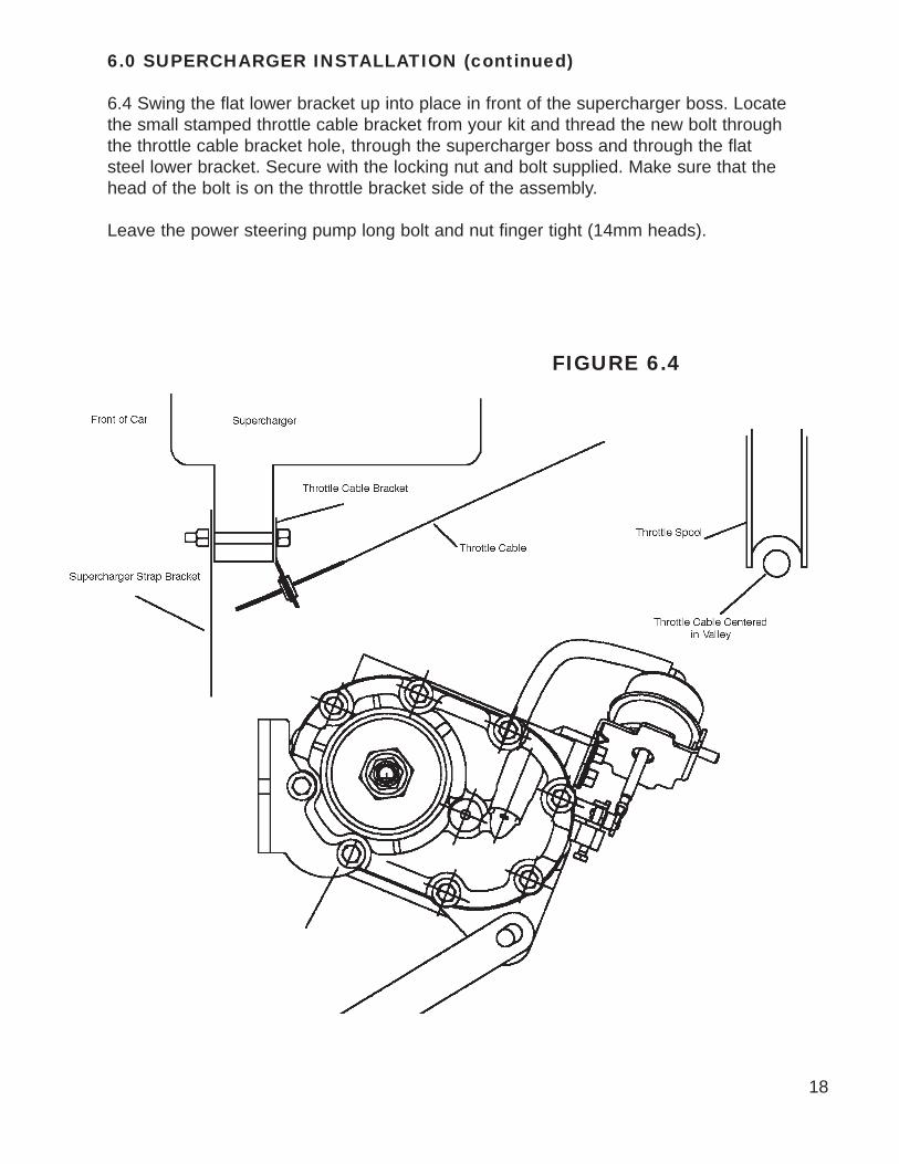
8.2 Locate the rubber sleeves and the front cross over pipe. Check the inside of thecross over pipe for debris - clean if necessary. Running a rag through the pipe pulledby a strong wire is a good way to do this. Install the cross over pipe between the idleair manifold (dummy throttle body now on the intake manifold) and the superchargerdischarge manifold. If you find the rubber sleeves hard to slip over their respectivelandings, use some spray light oil such as WD40 which dries off to lubricate the situa-tion. Do not use gasoline products or pure silicone products.
The best technique for installing the cross over tube involves putting the 2.75” diameterrubber sleeve on the supercharger manifold and the 2.5” diameter sleeve on the crossover tube, and attach both with clamps. Then install the cross over tube, starting at thesupercharger end first.
8.3 If you have cruise control, route the factory vacuum line from the cruise controlback to its original position, being careful to tie-wrap it away from the engine belts orradiator fans. Remove the steel spacer from one of the mounting grommets on yourstock Mazda air box. Use this 13/16” long spacer and the 6mm x 25mm hex head boltsupplied to secure your cruise control brace to the air filter base. The bolt will go verti-cally through the cruise control leg brace and into the small ledge with a threaded holeon the air filter base.
8.4 Once the cross over pipe is installed correctly, double check all your pipe and tubeconnections. There should be no loose ends or connections. Do not overtighten anyhose clamps, but ensure that they are snug. Double check your power steering beltand supercharger belt for correct tension. If the cross over tube is pressing too hardagainst your upper radiator hose, you can remove 3/4” to 1” from the radiator end ofthe hose to allow for more clearance, if you wish.You are now ready to start your engine.
8.5 First, crank your engine for a few seconds with the “FUEL INJ” relay still removedfrom step 1.1. Confirm that the supercharger belt stays on and that no other partshave been left unattended to.
8.6 Reinstall the “FUEL INJ” relay. Complete step 8.7 before starting your engine.
25

8.7 CLEARANCES
IMPORTANT!
MAKE SURE THAT YOU HAVE ATLEAST 3/4” INCH CLEARANCE
BETWEEN ANY ENGINE MOUNTEDCOMPONENT AND ANY BODY
MOUNTED COMPONENT.
CRITICAL AREAS:
BYPASS ACTUATOR TO BRAKE LINES (VERY CRITICAL - The engine “rocks” strongly to the driver’s side upon deceleration.
If clearance is too tight, your brake lines can be gently deformed away from the super-
charger bypass actuator by hand. )
SUPERCHARGER OUTLET MANIFOLDTO AIR FILTER (INCLUDING CLAMPS)
ALL VACUUM LINES TO THROTTLE SPOOL AND CABLE
26

9.0 ENGINE ADJUSTMENTS
9.1 SUPERCHARGER BELT DRIVE ADJUSTMENTStart your engine and observe your belt drive. The belt should line up with itself as itpasses between the two plastic idlers. To put it a different way, the portion of the beltrunning up to the supercharger should lay directly over the portion leaving the super-charger and heading toward the power steering pulley.
If the upward run is more forward or rearward than the downward run, you need tomove your supercharger slightly forward or backward with respect to the crankshaftpulley.
Remember the two bolts attaching the supercharger’s bracket to the cylinder headfrom step 6.1? You can now access these two bolts with an open end wrench. Looseneach bolt slightly to allow for adjustment. Start the engine. You can now move thesupercharger assembly slightly forward or rearward to correctly align the drive pulleys.The slots in the supercharger mounting bracket will allow you to find the perfect align-ment for the belt run.
NOTE: Do not attempt to move the supercharger with your hands with theengine running . Use an appropriate tool.
The best tool to use is a flat blade screw driver placed between the forward bracketbolt and the front inside edge of the bracket. Move the supercharger assembly whilewatching the belt run the idler pulley. If you have the two bracket bolts too loose, thesupercharger will be out of alignment from side to side. Make sure the two bolt aresnug enough to just allow some leveraged movement.
Once you have the belt running true in the center of the idler pulleys, tighten the rearbolt to secure the position. Shut off the engine and tighten the other bracket boltsecurely. Recheck all mounting bolts for tightness.
27

9.2 IDLE ADJUSTMENT: Restart your engine. Using the idle air screw on your throttle body (now on the back ofthe supercharger), adjust your idle speed to 950 rpm after the engine is warm. Thiscan best be approximated by closing the screw completely (turning clockwise) andbacking it out one and a half turns counter-clockwise. Adjust further to reach the 950rpm value.
28
FIGURE 9.2

9.2 IDLE ADJUSTMENT (continued)
Next, turn your headlights on BRIGHT and put your heater fan on HIGH. Leave the airconditioning off. Rev the engine briskly in neutral to at least 2500 rpm and release.Notice if the idle stops at 900 rpm. If it dips below this level and feels like it will stall,then recovers to 950 rpm, open the idle air screw (counterclockwise rotation) one tenthof a turn at a time until most of this “droop” disappears. A slight droop of 100 rpm orso is acceptable and normal. More than that may create a stalling problem during dri-ving. Turn off the lights and heater fan and double check that your idle speed is 950rpm.
If you open the idle screw too much, you will create too high of an idle speed when thelights and fan are turned off. You also may possibly introduce a stumble on part throttleto full throttle accelerations. In addition, a slow return to idle behavior will occur.
9.3 If you have difficulty stabilizing the drooping idle problem, adjust your dashpot tohelp in slowing the throttle’s closing. The factory specification is that the dashpot tipjust begins to touch the throttle arm at 2500 rpm. Have an assistant hold the engine at2500 rpm from the driver’s seat. The dashpot tip should just be touching the throttlearm. Adjust the dashpot so that this contact point is at 3000 rpm or more to help withthe drooping idle. Your Miata will drive best with the lowest idle speed possible withonly a slight droop in the idle (checked as described above with a warm engine, lightsand heater fan on high).
FIGURE 9.2B DASHPOT ADJUSTMENT
29

IGNITION TIMING AND FUEL QUALITY
9.4 Using a timing light, adjust your ignition timing to 8 degrees before top dead center(BTDC). You have to run a jumper wire ( an unfolded paper clip will do nicely)between terminals “GND” and “TEN” of your diagnostics center (located justabove the driver’s side shock absorber). The ignition timing is adjusted using the position sensor mounted at the firewall end ofthe intake camshaft. A 12mm box wrench will loosen the securing bolt. The 8 degreeBTDC mark is the one just to the right of the “10” degree mark on the crankshaft pulleyas viewed under a timing light.
IMPORTANT: PLEASE READ SECTION 9.5 IN ITS ENTIRETY
9.5 IGNITION TIMING AND FUEL QUALITY: Your Miata supercharger kit is designedto operate on 93 octane fuel. Make sure that any fuel you use meets this octane levelusing the R+M/2 method. Failure to use 93 octane fuel will result in engine-damagingdetonation. Make sure that you run your engine on 93 octane only, which means youshould completely burn up any lower octane gas in your tank and refill it with 93octane before installing your supercharger kit.
NOTE: If you can only find 92 octane fuel (R+M/2 method), set your timing to 6degrees BTDC instead of 8 degrees. If you live in an extremely hot area (temper-atures exceeding 100 degrees Fahrenheit), set your timing to 6 degrees BTDCfor an extra margin of safety. In any case, should you ever hear “pinging” orknocking from your engine when under acceleration, you should take measuresto eliminate this detonation, i.e. higher octane fuel or a further retardation inignition timing. NEVER CONTINUE TO OPERATE YOUR ENGINE IF YOU HEARANY SIGNS OF DETONATION (PINGING OR KNOCKING). YOU WILL QUICKLYMELT YOUR ENGINE DOWN!
This kit has been carefully designed to work within the stock Mazda engine parametersand no detonation will occur if the above settings and fuel are followed. The only waydetonation can creep into your situation is if your engine has a mechanical fault thefuel you are using is of the incorrect octane, if your timing is set incorrectly or if yourfuel filter is clogged. It is your responsibility as the installer of this kit to ensure that thesupercharger has been installed according to specification.
FIGURE 9.4
30

9.0 ADJUSTMENTS (continued)
9.5 IGNITION TIMING AND FUEL QUALITY (continued)
DRIVING TIP:If you should find yourself in a situation where you cannot find high octane fuel, youcan bypass the supercharger temporarily. Note the position the bypass actuator arm isin during idle. This is the position that bypasses the boost air back into the supercharg-er inlet. As you blip the throttle, the actuator arm will move and close a butterfly valveinside the bypass manifold. Using a short piece of wire, fix the bypass actuator arm inthe “bypass” position that it holds at idle. This will prevent boost from being developedand thus, detonation will not occur. Of course, your engine will now run like a stockMiata’s, but will be quite operable for as long as you need. When you find higheroctane fuel, simply remove the wire to release the actuator arm and the bypass willfunction normally, closing during acceleration, bypassing during idle and cruise. Try torun the low octane fuel out of your tank before filling up. Mixing fuels of different octanewill lower the overall rating and detonation could still be a problem.
You can order a special device that retards your timing during boosted condi-tions from Moss Motors. This is useful for those who can only find 92 octanefuel or wish to increase their low-end power by advancing the static ignition tim-ing. Call for details.
9.6 Starting procedure: Start your engine as you would a standard Miata. Rememberto bring the engine up to operating temperature (as indicated by your water tempera-ture gauge) before running it hard. Full boost on a cold engine will greatly increaseyour engine wear.
9.7 Oil changes: we suggest you use a synthetic oil such as Mobil 1 and change it reg-ularly (5000 miles maximum). If you use a mineral oil, change it every 2500 miles.While your supercharger does not use any engine oil for its lubrication, your engine willbe working a little harder with the addition of a supercharger. The synthetic oil providesan extra measure of protection, but is not necessary for safe and reliable operation.
9.8 Breaking-in: Your supercharger will work perfectly from the first time you fire it up.However, it does need about 500 miles to fully seat the rotors. Up to that time, youmay notice a slight noise coming from the supercharger at idle. This is normal.
9.9 Performance: You will notice that your engine runs stronger on cold days than onvery hot ones. This is due to the nature of the internal combustion engine. When theair is cold, the engine receives a denser charge of air, thus more power can be pro-duced. While this is true with any engine, the supercharger amplifies this cold air bene-fit.
31

10.0 LONG TERM MAINTENANCE10.1 BELTSThe only item to watch with your supercharger kit will be the belt tension for the super-charger drive. If you have a tension gauge for a poly-vee belt, the tension is to be 90pounds. Without a gauge, look for less than 1/4” deflection on the long run of the belt.If you see a large accumulation of belt dust on your supercharger, it is an indicationthat your belt is slipping. A slight amount of belt dust is normal.
CHECKING YOUR BELT FOR WEAR: As the belt wears, small cracks will form ineach of the ribs on the inside run of the belt. Replace your belt when you can count sixcracks within in one inch of length (six cracks total from all ribs combined). The correctbelt for power steering & air conditioning cars, or cars with just air conditioning is aGates K040520 (# 999-012), or equivalent. For cars with power steering but no airconditioning, the correct belt is a Gates K040480, (# 999-013) or equivalent. For carswithout air or power steering, the correct belt is a Gates K040445, (# 999-014) orequivalent.
10.2 DRIVEABILITYIf you notice a driveabilty problem as your car ages, have your fuel pressure checked.
The variable fuel regulator supplied with this kit increased your fuel injection system’spressure as boost is applied from the supercharger. Have a technician install an accu-rate 0-100 psi fuel pressure gauge in the fuel line BEFORE it enters the fuel rail (thefuel line you did not disturb during this installation). With the engine running, but thevacuum line to the auxiliary fuel pressure regulator disconnected, the fuel pressureshould be 48 to 52 psi. If it is not, the Allen head screw on top of the fuel regulator canbe retracted or tightened to adjust the base fuel pressure.
Using a small test pump and air pressure gauge, check for the following values in fuelpressure with the engine running:
VACUUM/BOOST SIGNAL FUEL LINE PRESSURETO FUEL PRESSURE REGULATOR AT INLET TO FUEL RAIL-10 in of Hg vacuum 35 psi +/- 2 psi
0 psi of boost 50 psi +/- 2 psi6 psi of boost 75 psi +/- 2 psi
The baseline value of 50 psi fuel pressure can be adjusted via the Allen head setscrew on top of the AFPR. Make sure to temporarily connect the vacuum line to cyclethe AFPR diaphragm when checking the baseline pressures.
The 75 psi of fuel pressure at 6 psi of boost must be available even when the engine isat 7000 rpm. If you participate in driving schools, race events, or drive your Miata veryhard, it is important that this flowrate is confirmed. Temporarily mounting a fuel pres-sure gauge on the outside of the windshield and having a passenger observe pressureat maximum rpm will prove the performance of your fuel pump and filter. As these com-ponents age, they can loose their deliverable flowrate. Less than 75 psi fuel pressureat these high flowrates (when the engine is consuming the maximum amount of fuel)will cause engine damage via detonation.
32

10.0 LONG TERM MAINTENANCE (continued)10.3 Every six months or so, check your hose clamps for correct tension. The rubber hoseswill take a set and the clamps may not be holding as tight. Also check all mounting bolts andnuts, particularly the throttle cable anchor bracket.
10.4 Your air filter is a long-life unit needing service only every 15,000 miles. To clean, youcan wash the filter element in soap and water. Use a dish detergent soap such as Dawn, etc.Rinse thoroughly and allow to dry. Wet the filter element with a light application of ATF (auto-matic transmission fluid). Alternatively, a special cleaning kit is available from Moss Motors (#901-970)
10.5 Once a year, check your fuel pressure values per the chart in step 10.2. Adjust if neces-sary.
10.6 At every oil change, lubricate the bypass actuator arm contact point and shaft bushingwith light grease to insure long life - these parts are exposed to underhood dirt and grime.
TROUBLESHOOTINGSYMPTOM: Engine cranks but will not startPROBABLE CAUSES: Airflow meter disconnected; Idle air line open; Low battery voltageCURE: Double check that seven pin to airflow meter is well connected. Re-check the 3/4” ICSline and the PCV line to see that they are not leaking. Use a known good battery to “jump”the Miata’s battery. It is possible to have enough voltage to crank a Miata but not enough tocorrectly run the engine’s control computer.
SYMPTOM: No power during boostPROBABLE CAUSES: Incorrect boost signal to Fuel Pressure Regulator, Pinched fuel lines,cross over tube loose.CURE: Check signal line to AFPR for 17 inches of Hg vacuum at idle, at least 5 psi of pres-sure during boost. Make sure line is not pinched or blocked. Make sure that line is attached tothe correct nipple on bypass block. Blow into the AFPR signal line to confirm that there is noleakage of boost signal air. Check fuel lines for kinking. Check the cross over tube to see thatit is well-connected at both ends.
SYMPTOM: Strong pulsating during acceleration (very rare) OR whistling/buzzing noise.PROBABLE CAUSE: A vibration in the AFPR set up by the fuel pump.CURE: Loosen the locking nut on the AFPR top center adjustment stud. Using an Allenwrench, tighten the screw 1/16 of a turn. Re-tighten the lock nut and check performance.Repeat as necessary, but do not exceed 1/4 turn on the adjustment screw under any circum-stances. If this does not eliminate the buzzing, rotate the adjustment screw back to where youstarted and LOOSEN it up to 1/4 turn. Stay within a plus or minus 1/4 turn range or you willhave to recalibrate the AFPR to the values outlined in step 9.2 above.
SYMPTOM: Unstable IdlePROBABLE CAUSE: Idle air screw set incorrectly; Restrictor left out in step #7.8; Pinchedidle air balance line; air leak in intake track. CURE: Re-check restrictor. Check idle adjustment procedure in step 8.1 above. Check theidle air balance line for restriction or pinching. Check for air leaks - vacuum at idle should beat least 17.7 in Hg.
33

11.0 FURTHER MODIFICATIONS
Now that your Miata has a stronger engine, there are a few changes you might want to make to therest of the car to improve its performance. The following are not required for your superchargedMiata, but are presented as tuning hints for a better all-around car.
b) We recommend that you install a Jackson Racing Carbon Kevlar clutch disc and pressure platewhen it comes time to put in a new clutch. While your new supercharger and the standard Mazdaclutch work well together, it is a good idea to step up to the Jackson Racing unit when you arechanging your clutch. Moss Motors sells these clutches (1-800-642-8295)
c) We recommend that you install good tires on your car. Specific tires to consider are the DunlopD60 A2, the Yokohama A509, the Dunlop SP 8000, or the Yokohama AVS Intermediate. We recom-mend that you use a 195/60 or a 195/55 tire in the 14 inch size, or a 195/50 in the 15 inch tire. Youmight consider increasing your rear tire width to 205 mm or 215 mm based on the higher power lev-els you are now transmitting to the pavement.
d) We recommend you install larger diameter anti-roll bars for the suspension for your Miata. Thesewill tighten up your steering response. We also recommend high quality shock absorbers if yourMiata has over 30,000 miles on it. We suggest the Koni product for the Miata with the lower springplatform on the lowest clip groove. This will lower your Miata about one half inch all around (JacksonRacing carries these components). Have your car aligned afterward (driver’s equivalent weight in thedriver’s seat) to factory specifications after any suspension changes.
e) You might want to ad a boost gauge to your supercharged Miata. One that fits nicely in one of thedash’s center vent holes is the 2-5/8” diameter AUTOMETER vacuum/boost gauge. These are avail-able directly from Sebring Superchargers. Both of the center dash vents can be replaced by gauges(boost plus clock, voltmeter, etc.) without a great loss in air conditioning performance except in thehottest of climates. For lighting, pick up the two leads that go to the ashtray light. Check polarity andoperation. The bulbs in the AUTOMETER gauges can be colored green with small boots (provided)rto match the Mazda lighting color.
f) A performance muffler will make your supercharged Miata that much faster. Since you are nowflowing 300 cubic feet per minute through a muffler designed for 177 cfm, an improvement can bemade. Dyno testing shows that the Jackson Racing final exhaust system makes the best horsepow-er.
g) Further performance improvements can be obtained through the use of an auxiliary computer tocontrol the Miata’s ignition curves. Sebring Superchargers has a boost timing unit that retards igni-tion timing under boost and a system that retards timing based on engine detonation. Other optionsare available-call for details.
WARRANTYThe supercharger unit itself carries a one year warranty (for the original purchaser of the kit) againstdefects in materials and workmanship. No other warranties apply. This warranty is void if the subjectvehicle is used in any racing activities of any sort.
HELPIf you experience any problems with your kit during installation or operation, contact your retailer orSebring Superchargers at 770/457-0107.
34


![1.6L 4-CYL 16-VALVE - VIN [A] Article Text - MR2OCopc.mr2oc.com/online_parts_catalog/1988-894agerebuild.pdf · Remove intake manifold and air control valve with ... 1.6L 4-CYL 16-VALVE](https://img.pdfslide.us/doc/110x75/5aa3fe537f8b9a2f048b9cdc/16l-4-cyl-16-valve-vin-a-article-text-intake-manifold-and-air-control-valve.jpg)