Embed Size (px)
Citation preview
I 1
BROADBAND
Optical broadband platform
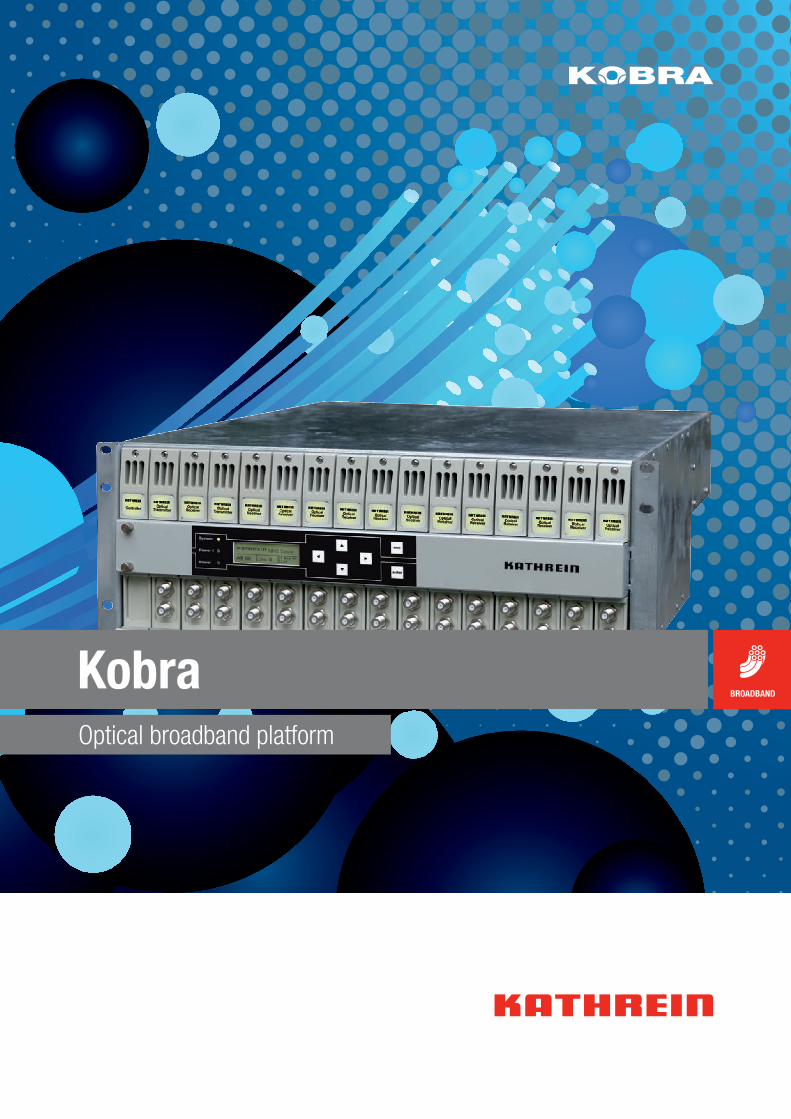
Kobra

2 I Kathrein I Company Portrait
Who we are and what we stand forKathrein is a leading international specialist for
reliable, high-quality communication technologies.
We are an innovation and technology leader in today’s
connected world. Our ability to provide solutions and sys-
tems enables people all over the world to communicate,
access information and use media, whether at home, at
the office or on the road. We cover a broad spectrum:
from mobile communication, signal enhancement and
data transmission in buildings, to fibre optic and cable
networks and satellite reception technology, to radio
and TV transmission and transmission and reception
systems in vehicles.
As a hidden champion and family-owned enterprise, we
have been working on the technologies of tomorrow since
1919. We take pride in our dedicated employees and our
passion for customers and quality.
Our Solutions
Find out more about us at www.kathrein.com
MOBILE COMMUNICATION INDOOR SAT BROADBAND BROADCAST AUTOMOTIVE
I 3KOBRA I Contents
KOBRA System overview 4
KOBRA System platform 8
19" broadband platform for optical modules 8
Network element controller modules Ethernet 9
Optical transmitters 10 Directly modulated broadcasting transmitters, 1310 nm,
extremely linear 10
Directly modulated broadcasting transmitters, 1547-1552 nm, extremely linear 13
Directly modulated broadcasting transmitters, DWDM 16
Externally modulated transmitters, KOBRA module 18
Optical receivers 20
Optical return path receiver, 2-way 20
Optical return path receivers, 4-way 22
RFoG return path receiver, 4-way 24
Optical downstream receiver 26
Optical amplifiers 27
Optical amplifiers, YEDFA 27
Optical amplifiers, YEDFA 28
Other modules 29
Optical fibre switch 29
Broadband amplifier, 5-1000 MHz 30
19" rack 31
Optical amplifiers, YEDFA 31
Externally modulated transmitters 32
4 I
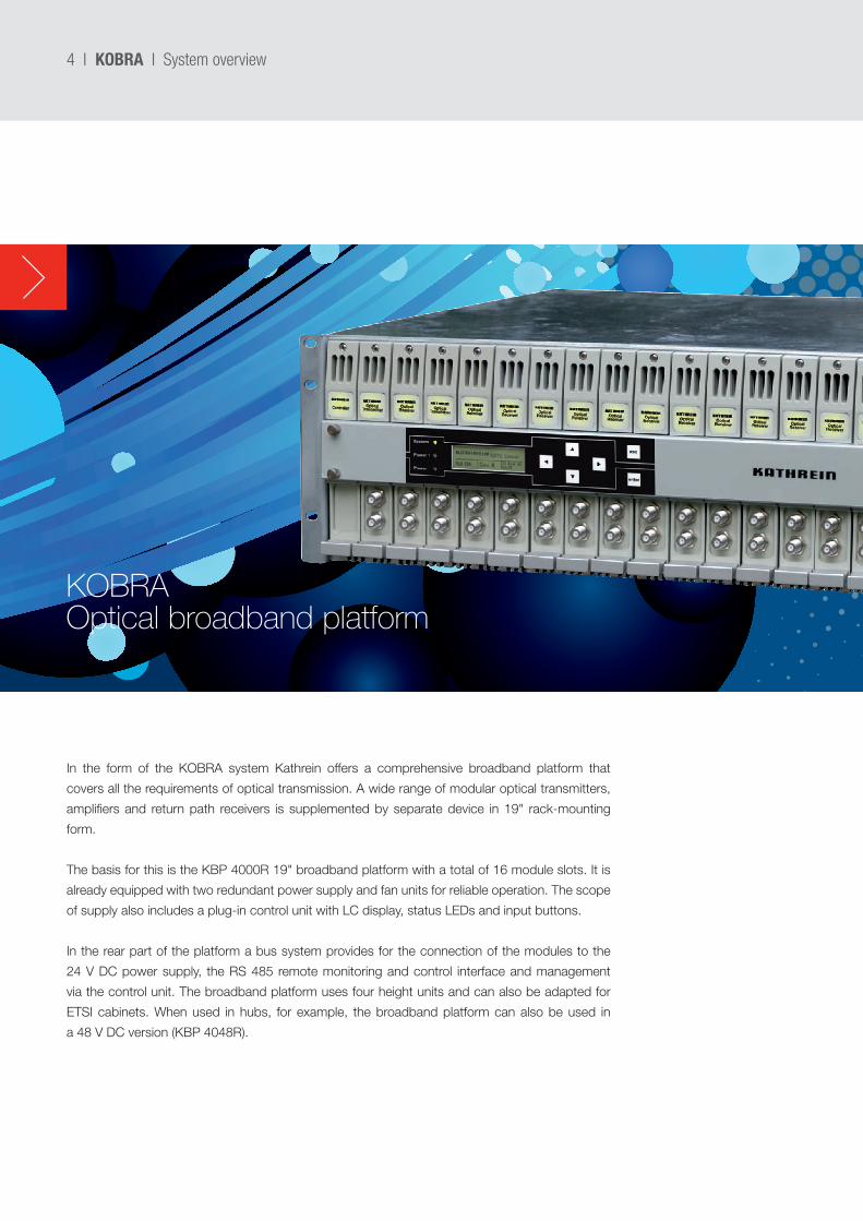
In the form of the KOBRA system Kathrein offers a comprehensive broadband platform that
covers all the requirements of optical transmission. A wide range of modular optical transmitters,
amplifiers and return path receivers is supplemented by separate device in 19" rack-mounting
form.
The basis for this is the KBP 4000R 19" broadband platform with a total of 16 module slots. It is
already equipped with two redundant power supply and fan units for reliable operation. The scope
of supply also includes a plug-in control unit with LC display, status LEDs and input buttons.
In the rear part of the platform a bus system provides for the connection of the modules to the
24 V DC power supply, the RS 485 remote monitoring and control interface and management
via the control unit. The broadband platform uses four height units and can also be adapted for
ETSI cabinets. When used in hubs, for example, the broadband platform can also be used in
a 48 V DC version (KBP 4048R).
KOBRAOptical broadband platform
KOBRA I System overview
I 5
Comprehensive management and monitoring options permit
flexible and reliable operation in any network configuration. The
plug-in control unit supplied in the basic configuration can make
all the settings required by the equipment.
The network element controller module Ethernet (NCM 10)
plays a central role here. On the one hand, it sets up the
connection from the control unit to all plugged-in modules via
the RS 485 bus. One NCM 10 can manage up to three fully
equipped KBP 4000R or 4048R broadband platforms.
On the other hand, it converts the RS 485 data into SNMP/
Ethernet and Web browser/Ethernet protocols. In this way all
settings and queries can also be handled by a PC with a Web
browser. In addition, it is possible to integrate the broadband
platform into any HMS-compliant monitoring system, such as
the KOM communication system from Kathrein.
Together with the optical compact receivers from Kathrein, an
optical distribution system that meet all requirements can be
set up with the KOBRA broadband platform. As a result of the
modular design and the wide-ranging selection of products that
are available, all application cases ranging from a simple optical
connection via classic HFC structures up to video distribution in
FttH networks is possible and economically viable.
Kathrein constantly develops its products further and expands
its range of products. Further product variations are available on
request.
Optical broadband platform for up to
16 modules
Equipped with two redundant power supply and
fan units
Large selection of optical transmitters, amplifiers
and return path receivers
All optical and electrical connections at the rear
panel, test sockets at the front panel
Integration into any HMS-compliant monitoring
system is possible
Plug-in control unit with LC display, LEDs and
input buttons
Settings and management also via
a Web browser
RS 485 remote monitoring and control interface
Management of multiple optical broadband
platforms with one controller module is possible
Automatic redundant operation of
adjacent modules
High reliability due to dust-tight modules and
large cooling ribs
Versions with mains voltage (100 - 240 V AC)
and direct current (36 - 72 V DC)
Installation height/construction:
19" rack with four height units (HU)
Features in overview
KOBRA I System overview
Note: All data are typical values, unless stated otherwise.
6 I
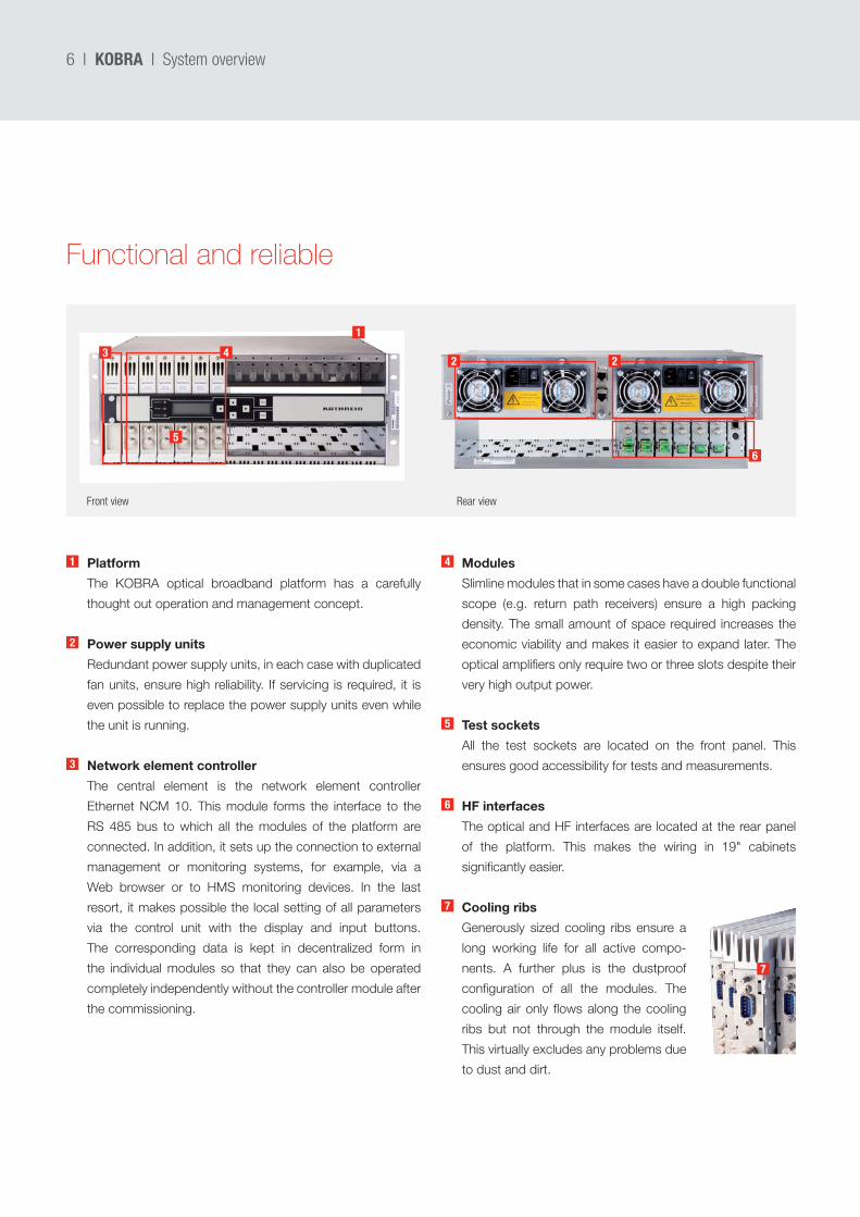
Modules
Slimline modules that in some cases have a double functional
scope (e.g. return path receivers) ensure a high packing
density. The small amount of space required increases the
economic viability and makes it easier to expand later. The
optical amplifiers only require two or three slots despite their
very high output power.
Test sockets
All the test sockets are located on the front panel. This
ensures good accessibility for tests and measurements.
HF interfaces
The optical and HF interfaces are located at the rear panel
of the platform. This makes the wiring in 19" cabinets
significantly easier.
Cooling ribs
Generously sized cooling ribs ensure a
long working life for all active compo-
nents. A further plus is the dustproof
configuration of all the modules. The
cooling air only flows along the cooling
ribs but not through the module itself.
This virtually excludes any problems due
to dust and dirt.
Functional and reliable
Platform
The KOBRA optical broadband platform has a carefully
thought out operation and management concept.
Power supply units
Redundant power supply units, in each case with duplicated
fan units, ensure high reliability. If servicing is required, it is
even possible to replace the power supply units even while
the unit is running.
Network element controller
The central element is the network element controller
Ethernet NCM 10. This module forms the interface to the
RS 485 bus to which all the modules of the platform are
connected. In addition, it sets up the connection to external
management or monitoring systems, for example, via a
Web browser or to HMS monitoring devices. In the last
resort, it makes possible the local setting of all parameters
via the control unit with the display and input buttons.
The corresponding data is kept in decentralized form in
the individual modules so that they can also be operated
completely independently without the controller module after
the commissioning.
KOBRA I System overview
Front view Rear view
1
2
3
4
5
6
7
7
6
5
432 2
1
I 7
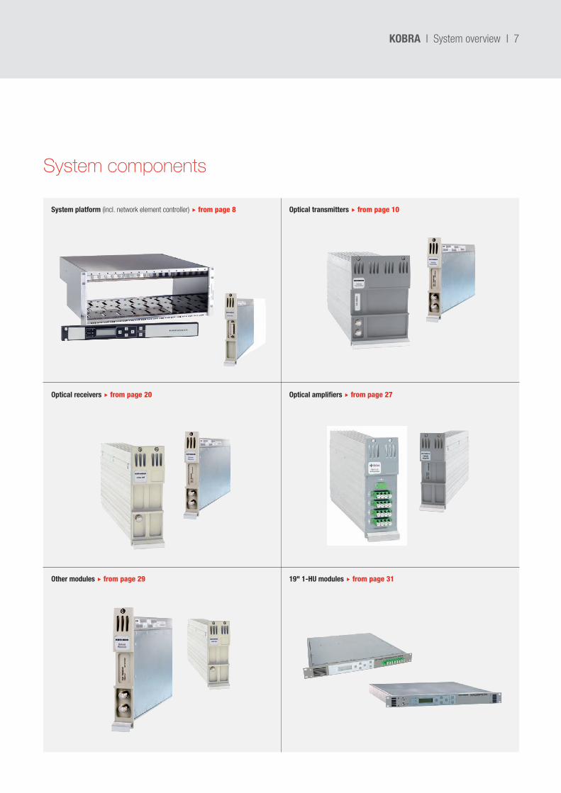
System components
Optical receivers from page 20
System platform (incl. network element controller) from page 8
Optical amplifiers from page 27
Optical transmitters from page 10
19" 1-HU modules from page 31Other modules from page 29
KOBRA I System overview
8 I
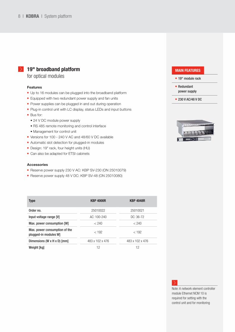
19" broadband platformfor optical modules 19“ module rack
Redundant power supply
230 V AC/48 V DC
MAIN FEATURES
Type KBP 4000R KBP 4048R
Order no. 25010022 25010021
Input voltage range [V] AC: 100-240 DC: 36-72
Max. power consumption [W] < 240 < 240
Max. power consumption of the plugged-in modules W]
< 192 < 192
Dimensions (W x H x D) [mm] 483 x 102 x 476 483 x 102 x 476
Weight [kg] 12 12
Note: A network element controller module Ethernet NCM 10 is required for setting with the control unit and for monitoring
Features
Up to 16 modules can be plugged into the broadband platform
Equipped with two redundant power supply and fan units
Power supplies can be plugged in and out during operation
Plug-in control unit with LC display, status LEDs and input buttons
Bus for:
•24VDCmodulepowersupply
•RS485remotemonitoringandcontrolinterface
•Managementforcontrolunit
Versions for 100 - 240 V AC and 48/60 V DC available
Automatic slot detection for plugged-in modules
Design: 19" rack, four height units (HU)
Can also be adapted for ETSI cabinets
Accessories
Reserve power supply 230 V AC: KBP SV-230 (ON 25010079)
Reserve power supply 48 V DC: KBP SV-48 (ON 25010080)
KOBRA I System platform
I 9
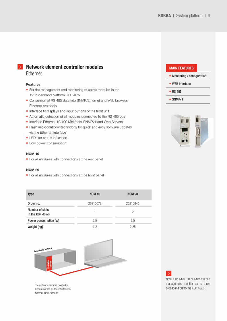
Network element controller modulesEthernet Monitoring / configuration
WEB interface
RS 485
SNMPv1
Type NCM 10 NCM 20
Order no. 26210079 26210845
Number of slots in the KBP 40xxR
1 2
Power consumption [W] 2.5 2.5
Weight [kg] 1.2 2.25
Features
For the management and monitoring of active modules in the
19" broadband platform KBP 40xx
Conversion of RS 485 data into SNMP/Ethernet and Web browser/
Ethernet protocols
Interface to displays and input buttons of the front unit
Automatic detection of all modules connected to the RS 485 bus
Interface Ethernet 10/100 Mbit/s for SNMPv1 and Web Servers
Flash microcontroller technology for quick and easy software updates
via the Ethernet interface
LEDs for status indication
Low power consumption
NCM 10
For all modules with connections at the rear panel
NCM 20
For all modules with connections at the front panel
Note: One NCM 10 or NCM 20 can manage and monitor up to three broadband platforms KBP 40xxR
KOBRA I System platform
The network element controller module serves as the interface to external input devices
Broadband platform
Cont
rolle
r m
odul
e
MAIN FEATURES
10 I
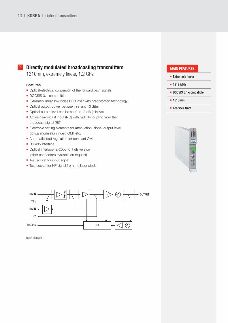
Directly modulated broadcasting transmitters1310 nm, extremely linear, 1.2 GHz Extremely linear
1218 MHz
DOCSIS 3.1-compatible
1310 nm
AM-VSB, QAM
Features
Optical-electrical conversion of the forward path signals
DOCSIS 3.1-compatible
Extremely linear, low noise DFB laser with predistortion technology
Optical output power between +8 and 13 dBm
Optical output level can be set 0 to -3 dB (relative)
Active narrowcast input (NC) with high decoupling from the
broadcast signal (BC)
Electronic setting elements for attenuation, slope, output level,
optical modulation index (OMI) etc.
Automatic load regulation for constant OMI
RS 485 interface
Optical interface: E-2000, 0.1 dB version
(other connectors available on request)
Test socket for input signal
Test socket for HF signal from the laser diode
KOBRA I Optical transmitters
µC
BC IN OUTPUT
BC IN
RS 485
TP1
TP2
Block diagram
MAIN FEATURES
I 11KOBRA I Optical transmitters
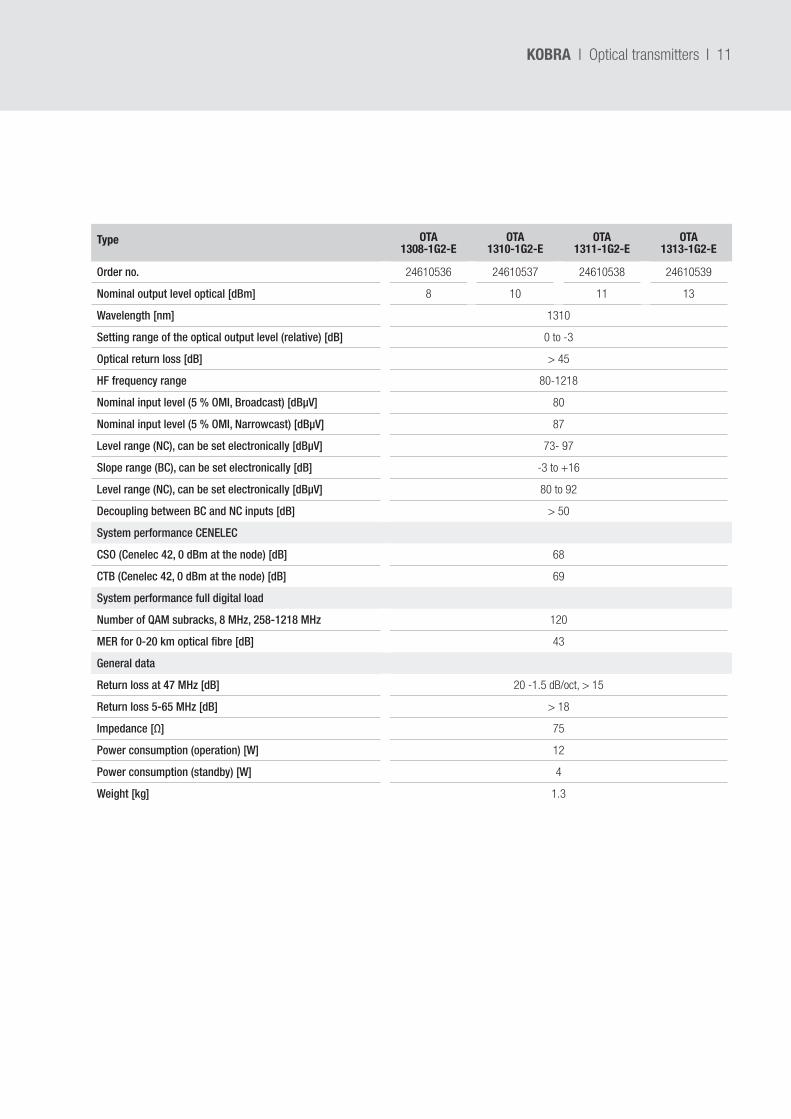
Type OTA 1308-1G2-E
OTA 1310-1G2-E
OTA 1311-1G2-E
OTA 1313-1G2-E
Order no. 24610536 24610537 24610538 24610539
Nominal output level optical [dBm] 8 10 11 13
Wavelength [nm] 1310
Setting range of the optical output level (relative) [dB] 0 to -3
Optical return loss [dB] > 45
HF frequency range 80-1218
Nominal input level (5 % OMI, Broadcast) [dBµV] 80
Nominal input level (5 % OMI, Narrowcast) [dBµV] 87
Level range (NC), can be set electronically [dBµV] 73- 97
Slope range (BC), can be set electronically [dB] -3 to +16
Level range (NC), can be set electronically [dBµV] 80 to 92
Decoupling between BC and NC inputs [dB] > 50
System performance CENELEC
CSO (Cenelec 42, 0 dBm at the node) [dB] 68
CTB (Cenelec 42, 0 dBm at the node) [dB] 69
System performance full digital load
Number of QAM subracks, 8 MHz, 258-1218 MHz 120
MER for 0-20 km optical fibre [dB] 43
General data
Return loss at 47 MHz [dB] 20 -1.5 dB/oct, > 15
Return loss 5-65 MHz [dB] > 18
Impedance [Ω] 75
Power consumption (operation) [W] 12
Power consumption (standby) [W] 4
Weight [kg] 1.3
12 I
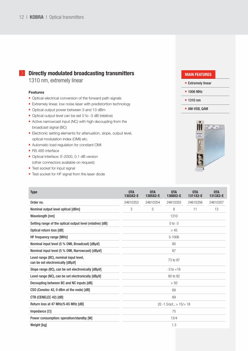
Directly modulated broadcasting transmitters1310 nm, extremely linear
Features
Optical-electrical conversion of the forward path signals
Extremely linear, low noise laser with predistortion technology
Optical output power between 3 and 13 dBm
Optical output level can be set 0 to -3 dB (relative)
Active narrowcast input (NC) with high decoupling from the
broadcast signal (BC)
Electronic setting elements for attenuation, slope, output level,
optical modulation index (OMI) etc.
Automatic load regulation for constant OMI
RS 485 interface
Optical interface: E-2000, 0.1 dB version
(other connectors available on request)
Test socket for input signal
Test socket for HF signal from the laser diode
KOBRA I Optical transmitters
Extremely linear
1006 MHz
1310 nm
AM-VSB, QAM
Type OTA1303X2-E
OTA 1305X2-E
OTA 1308X2-E
OTA 1311X2-E
OTA 1313X2-E
Order no. 24610353 24610354 24610355 24610356 24610357
Nominal output level optical [dBm] 3 5 8 11 13
Wavelength [nm] 1310
Setting range of the optical output level (relative) [dB] 0 to -3
Optical return loss [dB] > 45
HF frequency range [MHz] 5-1006
Nominal input level (5 % OMI, Broadcast) [dBµV] 80
Nominal input level (5 % OMI, Narrowcast) [dBµV] 87
Level range (BC), nominal input level, can be set electronically [dBµV]
73 to 97
Slope range (BC), can be set electronically [dBµV] -3 to +16
Level range (NC), can be set electronically [dBµV] 80 to 92
Decoupling between BC and NC inputs [dB] > 50
CSO (Cenelec 42, 0 dBm at the node) [dB] 68
CTB (CENELEC 42) [dB] 69
Return loss at 47 MHz/5-65 MHz [dB] 20 -1.5/oct., > 15/> 18
Impedance [Ω] 75
Power consumption: operation/standby [W] 12/4
Weight [kg] 1.3
MAIN FEATURES
I 13KOBRA I Optical transmitters
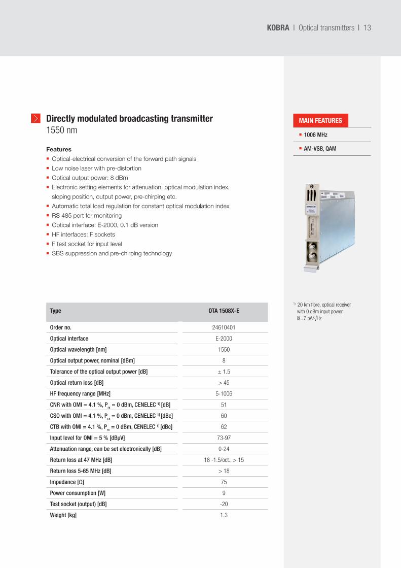
Directly modulated broadcasting transmitter1550 nm 1006 MHz
AM-VSB, QAM
Type OTA 1508X-E
Order no. 24610401
Optical interface E-2000
Optical wavelength [nm] 1550
Optical output power, nominal [dBm] 8
Tolerance of the optical output power [dB] ± 1.5
Optical return loss [dB] > 45
HF frequency range [MHz] 5-1006
CNR with OMI = 4.1 %, Prx = 0 dBm, CENELEC ¹] [dB] 51
CSO with OMI = 4.1 %, Prx = 0 dBm, CENELEC ¹] [dBc] 60
CTB with OMI = 4.1 %, Prx = 0 dBm, CENELEC ¹] [dBc] 62
Input level for OMI = 5 % [dBµV] 73-97
Attenuation range, can be set electronically [dB] 0-24
Return loss at 47 MHz [dB] 18 -1.5/oct., > 15
Return loss 5-65 MHz [dB] > 18
Impedance [Ω] 75
Power consumption [W] 9
Test socket (output) [dB] -20
Weight [kg] 1.3
Features
Optical-electrical conversion of the forward path signals
Low noise laser with pre-distortion
Optical output power: 8 dBm
Electronic setting elements for attenuation, optical modulation index,
sloping position, output power, pre-chirping etc.
Automatic total load regulation for constant optical modulation index
RS 485 port for monitoring
Optical interface: E-2000, 0.1 dB version
HF interfaces: F sockets
F test socket for input level
SBS suppression and pre-chirping technology
1) 20 km fibre, optical receiver with 0 dBm input power, Iä=7 pA/√Hz
MAIN FEATURES
14 I
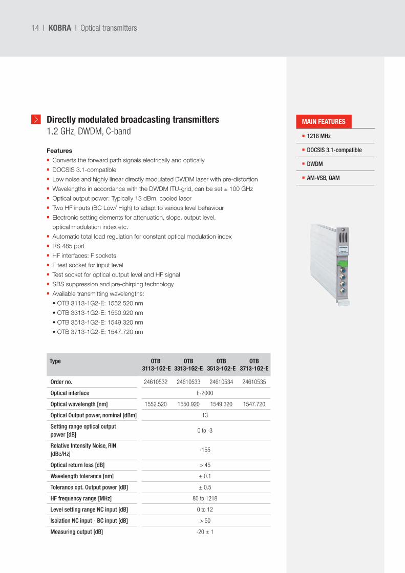
Directly modulated broadcasting transmitters1.2 GHz, DWDM, C-band
KOBRA I Optical transmitters
1218 MHz
DOCSIS 3.1-compatible
DWDM
AM-VSB, QAM
Type OTB 3113-1G2-E
OTB 3313-1G2-E
OTB 3513-1G2-E
OTB 3713-1G2-E
Order no. 24610532 24610533 24610534 24610535
Optical interface E-2000
Optical wavelength [nm] 1552.520 1550.920 1549.320 1547.720
Optical Output power, nominal [dBm] 13
Setting range optical output power [dB]
0 to -3
Relative Intensity Noise, RIN [dBc/Hz]
-155
Optical return loss [dB] > 45
Wavelength tolerance [nm] ± 0.1
Tolerance opt. Output power [dB] ± 0.5
HF frequency range [MHz] 80 to 1218
Level setting range NC input [dB] 0 to 12
Isolation NC input - BC input [dB] > 50
Measuring output [dB] -20 ± 1
Features
Converts the forward path signals electrically and optically
DOCSIS 3.1-compatible
Low noise and highly linear directly modulated DWDM laser with pre-distortion
Wavelengths in accordance with the DWDM ITU-grid, can be set ± 100 GHz
Optical output power: Typically 13 dBm, cooled laser
Two HF inputs (BC Low/ High) to adapt to various level behaviour
Electronic setting elements for attenuation, slope, output level,
optical modulation index etc.
Automatic total load regulation for constant optical modulation index
RS 485 port
HF interfaces: F sockets
F test socket for input level
Test socket for optical output level and HF signal
SBS suppression and pre-chirping technology
Available transmitting wavelengths:
•OTB3113-1G2-E:1552.520nm
•OTB3313-1G2-E:1550.920nm
•OTB3513-1G2-E:1549.320nm
•OTB3713-1G2-E:1547.720nm
MAIN FEATURES
I 15KOBRA I Optical transmitters
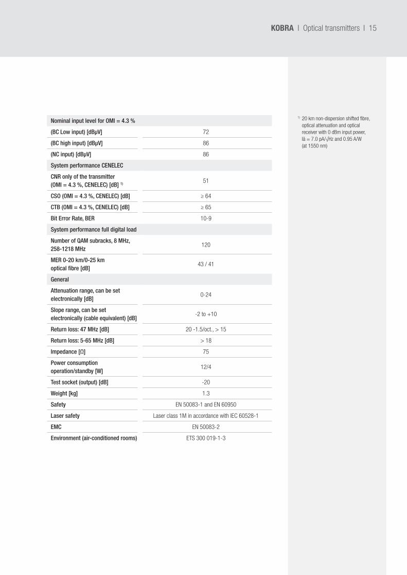
1) 20 km non-dispersion shifted fibre, optical attenuation and optical receiver with 0 dBm input power, Iä = 7.0 pA/√Hz and 0.95 A/W (at 1550 nm)
Nominal input level for OMI = 4.3 %
(BC Low input) [dBµV] 72
(BC high input) [dBµV] 86
(NC input) [dBµV] 86
System performance CENELEC
CNR only of the transmitter (OMI = 4.3 %, CENELEC) [dB] 1) 51
CSO (OMI = 4.3 %, CENELEC) [dB] ≥ 64
CTB (OMI = 4.3 %, CENELEC) [dB] ≥ 65
Bit Error Rate, BER 10-9
System performance full digital load
Number of QAM subracks, 8 MHz, 258-1218 MHz
120
MER 0-20 km/0-25 km optical fibre [dB]
43 / 41
General
Attenuation range, can be set electronically [dB]
0-24
Slope range, can be set electronically (cable equivalent) [dB]
-2 to +10
Return loss: 47 MHz [dB] 20 -1.5/oct., > 15
Return loss: 5-65 MHz [dB] > 18
Impedance [Ω] 75
Power consumption operation/standby [W]
12/4
Test socket (output) [dB] -20
Weight [kg] 1.3
Safety EN 50083-1 and EN 60950
Laser safety Laser class 1M in accordance with IEC 60528-1
EMC EN 50083-2
Environment (air-conditioned rooms) ETS 300 019-1-3
16 I
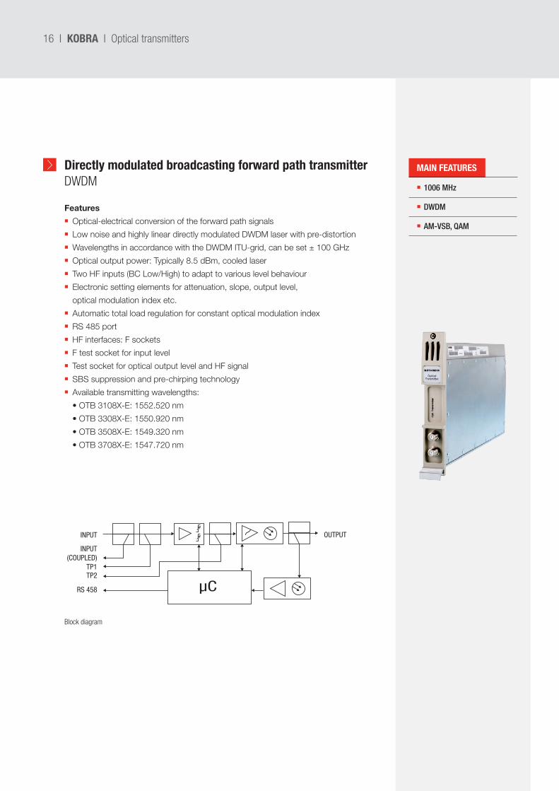
Directly modulated broadcasting forward path transmitterDWDM
Features
Optical-electrical conversion of the forward path signals
Low noise and highly linear directly modulated DWDM laser with pre-distortion
Wavelengths in accordance with the DWDM ITU-grid, can be set ± 100 GHz
Optical output power: Typically 8.5 dBm, cooled laser
Two HF inputs (BC Low/High) to adapt to various level behaviour
Electronic setting elements for attenuation, slope, output level,
optical modulation index etc.
Automatic total load regulation for constant optical modulation index
RS 485 port
HF interfaces: F sockets
F test socket for input level
Test socket for optical output level and HF signal
SBS suppression and pre-chirping technology
Available transmitting wavelengths:
•OTB3108X-E:1552.520nm
•OTB3308X-E:1550.920nm
•OTB3508X-E:1549.320nm
•OTB3708X-E:1547.720nm
KOBRA I Optical transmitters
µC
INPUT OUTPUT
TP1TP2
RS 458
INPUT(COUPLED)
1006 MHz
DWDM
AM-VSB, QAM
Block diagram
MAIN FEATURES
I 17
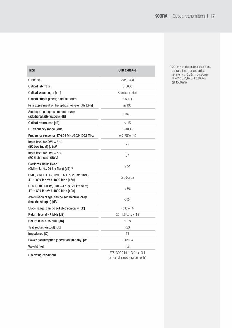
Type OTB xx08X-E
Order no. 2461043x
Optical interface E-2000
Optical wavelength [nm] See description
Optical output power, nominal [dBm] 8.5 ± 1
Fine adjustment of the optical wavelength [GHz] ± 100
Setting range optical output power (additional attenuation) [dB]
0 to 3
Optical return loss [dB] > 45
HF frequency range [MHz] 5-1006
Frequency response 47-862 MHz/862-1002 MHz ± 0.75/± 1.5
Input level for OMI = 5 % (BC Low input) [dBµV]
73
Input level for OMI = 5 % (BC High input) [dBµV]
87
Carrier to Noise Ratio (OMI = 4.1 %, 20 km fibre) [dB] ¹) ≥ 51
CSO (CENELEC 42, OMI = 4.1 %, 20 km fibre) 47 to 600 MHz/47-1002 MHz [dBc]
≥ 60/≥ 55
CTB (CENELEC 42, OMI = 4.1 %, 20 km fibre) 47 to 600 MHz/47-1002 MHz [dBc]
≥ 62
Attenuation range, can be set electronically (broadcast input) [dB]
0-24
Slope range, can be set electronically [dB] -3 to +16
Return loss at 47 MHz [dB] 20 -1.5/oct., > 15
Return loss 5-65 MHz [dB] > 18
Test socket (output) [dB] -20
Impedance [Ω] 75
Power consumption (operation/standby) [W] ≤ 12/≤ 4
Weight [kg] 1.3
Operating conditionsETSI 300 019-1-3 Class 3.1
(air-conditioned environments)
KOBRA I Optical transmitters
1) 20 km non-dispersion shifted fibre, optical attenuation and optical receiver with 0 dBm input power, Iä = 7.0 pA/√Hz and 0.95 A/W (at 1550 nm)
18 I
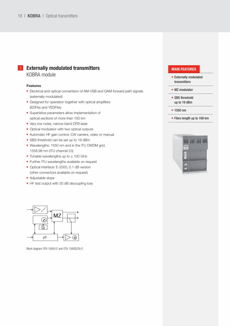
Externally modulated transmitters KOBRA module Externally modulated
transmitters
MZ modulator
SBS threshold up to 19 dBm
1550 nm
Fibre length up to 100 km
Features
Electrical and optical convertsion of AM-VSB and QAM forward path signals
(externally modulated)
Designed for operation together with optical amplifiers
(EDFAs and YEDFAs)
Superlative parameters allow implementation of
optical sections of more than 100 km
Very low noise, narrow band DFB laser
Optical modulator with two optical outputs
Automatic HF gain control: CW carriers, video or manual
SBS threshold can be set up to 19 dBm
Wavelengths: 1550 nm and in the ITU DWDM grid,
1558.98 nm (ITU channel 23)
Tunable wavelengths up to ± 100 GHz
Further ITU wavelengths available on request
Optical interface: E-2000, 0.1 dB version
(other connectors available on request)
Adjustable slope
HF test output with 20 dB decoupling loss
KOBRA I Optical transmitters
µC
MZ
G
Block diagram OTA 1585X-E and OTA 1585D23X-E
MAIN FEATURES
I 19
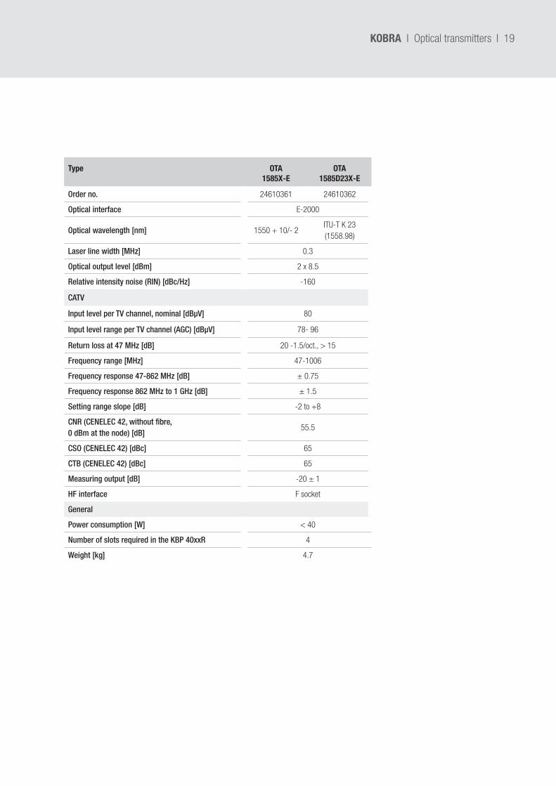
Type OTA 1585X-E
OTA 1585D23X-E
Order no. 24610361 24610362
Optical interface E-2000
Optical wavelength [nm] 1550 + 10/- 2ITU-T K 23 (1558.98)
Laser line width [MHz] 0.3
Optical output level [dBm] 2 x 8.5
Relative intensity noise (RIN) [dBc/Hz] -160
CATV
Input level per TV channel, nominal [dBµV] 80
Input level range per TV channel (AGC) [dBµV] 78- 96
Return loss at 47 MHz [dB] 20 -1.5/oct., > 15
Frequency range [MHz] 47-1006
Frequency response 47-862 MHz [dB] ± 0.75
Frequency response 862 MHz to 1 GHz [dB] ± 1.5
Setting range slope [dB] -2 to +8
CNR (CENELEC 42, without fibre, 0 dBm at the node) [dB]
55.5
CSO (CENELEC 42) [dBc] 65
CTB (CENELEC 42) [dBc] 65
Measuring output [dB] -20 ± 1
HF interface F socket
General
Power consumption [W] < 40
Number of slots required in the KBP 40xxR 4
Weight [kg] 4.7
KOBRA I Optical transmitters
20 I
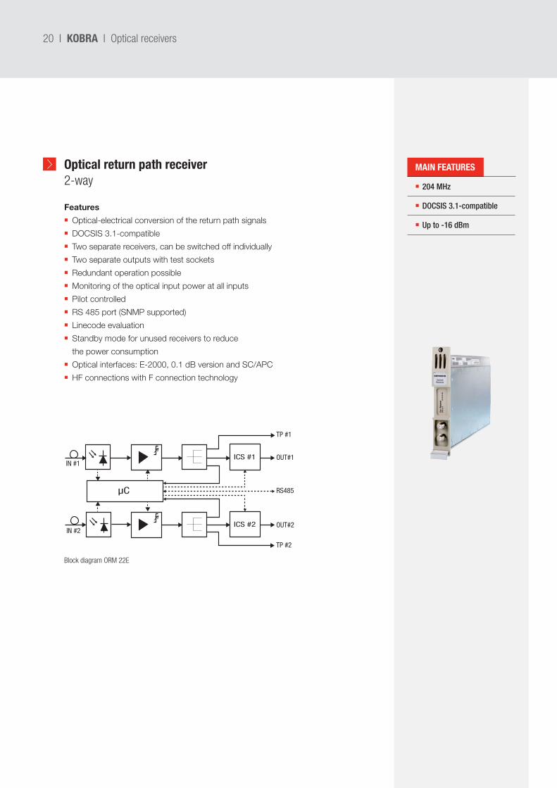
Optical return path receiver 2-way 204 MHz
DOCSIS 3.1-compatible
Up to -16 dBm
Features
Optical-electrical conversion of the return path signals
DOCSIS 3.1-compatible
Two separate receivers, can be switched off individually
Two separate outputs with test sockets
Redundant operation possible
Monitoring of the optical input power at all inputs
Pilot controlled
RS 485 port (SNMP supported)
Linecode evaluation
Standby mode for unused receivers to reduce
the power consumption
Optical interfaces: E-2000, 0.1 dB version and SC/APC
HF connections with F connection technology
KOBRA I Optical receivers
IN #1
TP #1
TP #2
OUT#1
RS485
OUT#2IN #2
µC
ICS #1
ICS #2
Block diagram ORM 22E
MAIN FEATURES
I 21
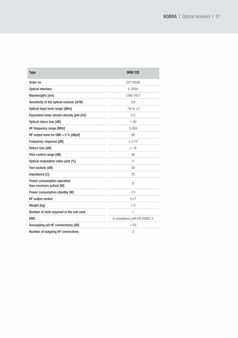
Type ORM 22E
Order no. 24710026
Optical interface E-2000
Wavelengths [nm] 1280-1611
Sensitivity of the optical receiver [A/W] 0.8
Optical input level range [dBm] -16 to +2
Equivalent noise stream density [pA/√Hz] 2.5
Optical return loss [dB] > 40
HF frequency range [MHz] 5-204
HF output level for OMI = 5 % [dBµV] 90
Frequency response [dB] ± 0.75
Return loss [dB] > 19
Pilot control range [dB] 36
Optical modulation index pilot [%] 5
Test sockets [dB] 20
Impedance [Ω] 75
Power consumption operation (two receivers active) [W]
6
Power consumption standby [W] 1.5
HF output socket 2 x F
Weight [kg] 1.3
Number of slots required in the sub-rack 1
EMC In compliance with EN 50083-2
Decoupling (all HF connections) [dB] ≥ 50
Number of outgoing HF connections 2
KOBRA I Optical receivers
22 I
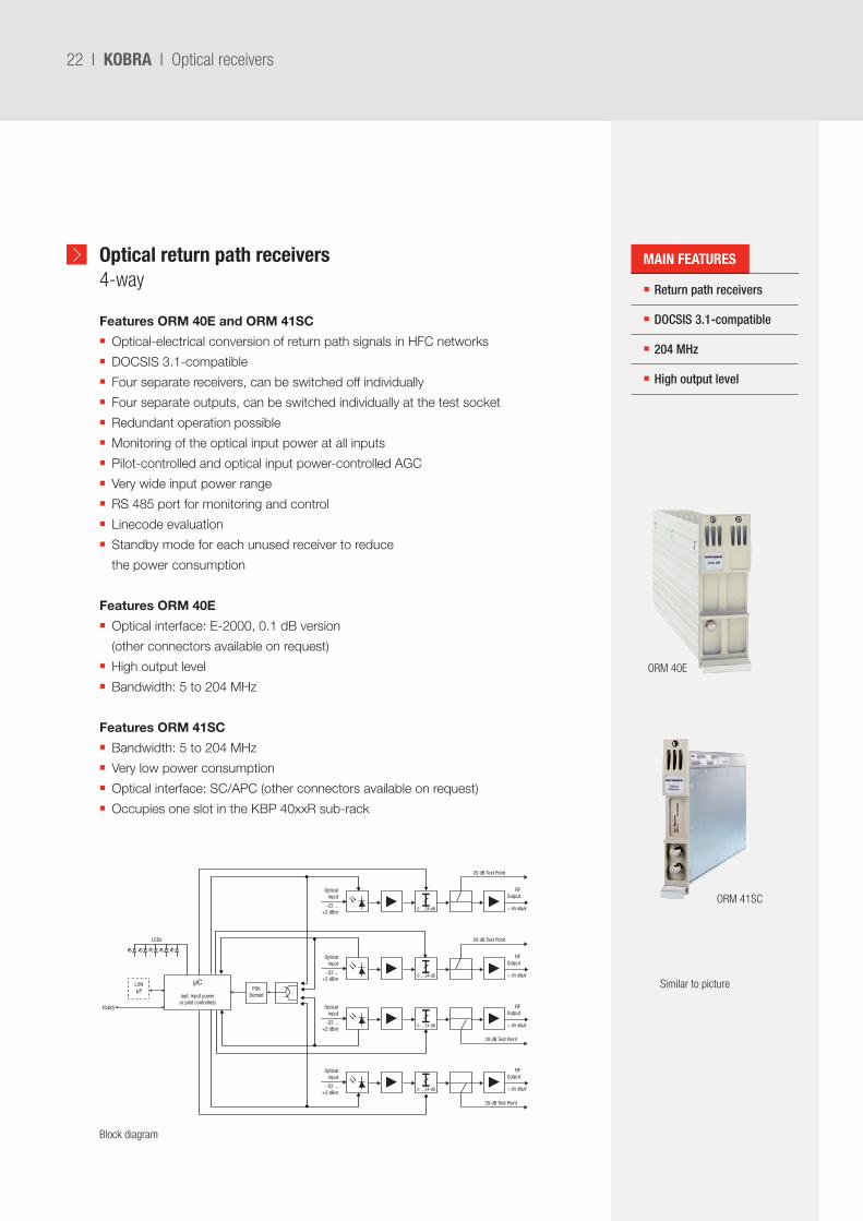
Optical return path receivers4-way Return path receivers
DOCSIS 3.1-compatible
204 MHz
High output level
Features ORM 40E and ORM 41SC
Optical-electrical conversion of return path signals in HFC networks
DOCSIS 3.1-compatible
Four separate receivers, can be switched off individually
Four separate outputs, can be switched individually at the test socket
Redundant operation possible
Monitoring of the optical input power at all inputs
Pilot-controlled and optical input power-controlled AGC
Very wide input power range
RS 485 port for monitoring and control
Linecode evaluation
Standby mode for each unused receiver to reduce
the power consumption
Features ORM 40E
Optical interface: E-2000, 0.1 dB version
(other connectors available on request)
High output level
Bandwidth: 5 to 204 MHz
Features ORM 41SC
Bandwidth: 5 to 204 MHz
Very low power consumption
Optical interface: SC/APC (other connectors available on request)
Occupies one slot in the KBP 40xxR sub-rack
Opticalinput
20 dB Test Point
RFOutput
> 85 dBµV -22 ...+2 dBm
0 ... 24 dB
Opticalinput
20 dB Test Point
RFOutput
> 85 dBµV -22 ...+2 dBm
0 ... 24 dB
Opticalinput
20 dB Test Point
RFOutput
> 85 dBµV -22 ...+2 dBm
0 ... 24 dB
Opticalinput
20 dB Test Point
RFOutput
> 85 dBµV -22 ...+2 dBm
0 ... 24 dB
µCPSK
Demod
LONµP
(opt. input poweror pilot controlled)
LEDs
RS485
KOBRA I Optical receivers
Similar to picture
ORM 41SC
ORM 40E
Block diagram
MAIN FEATURES
I 23
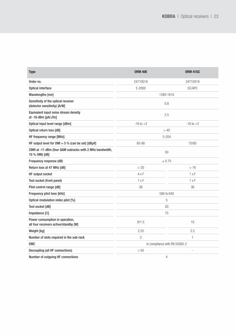
Type ORM 40E ORM 41SC
Order no. 24710018 24710019
Optical interface E-2000 SC/APC
Wavelengths [nm] 1280-1610
Sensitivity of the optical receiver (detector sensitivity) [A/W]
0.8
Equivalent input noise stream density at -16 dBm [pA/√Hz]
2.5
Optical input level range [dBm] -16 to +2 -18 to +2
Optical return loss [dB] > 45
HF frequency range [MHz] 5-204
HF output level for OMI = 5 % (can be set) [dBµV] 65-90 75/85
CINR at -11 dBm (four QAM subracks with 2 MHz bandwidth, 10 % OMI) [dB]
50
Frequency response (dB) ± 0.75
Return loss at 47 MHz [dB] > 20 > 16
HF output socket 4 x F 1 x F
Test socket (front panel) 1 x F 1 x F
Pilot control range [dB] 26 36
Frequency pilot tone [kHz] 590 to 640
Optical modulation index pilot [%] 5
Test socket [dB] 20
Impedance [Ω] 75
Power consumption in operation, all four receivers active/standby [W]
8/1.5 10
Weight [kg] 2.25 2.2
Number of slots required in the sub-rack 2 1
EMC In compliance with EN 50083-2
Decoupling (all HF connections) ≥ 50 -
Number of outgoing HF connections 4
KOBRA I Optical receivers
24 I
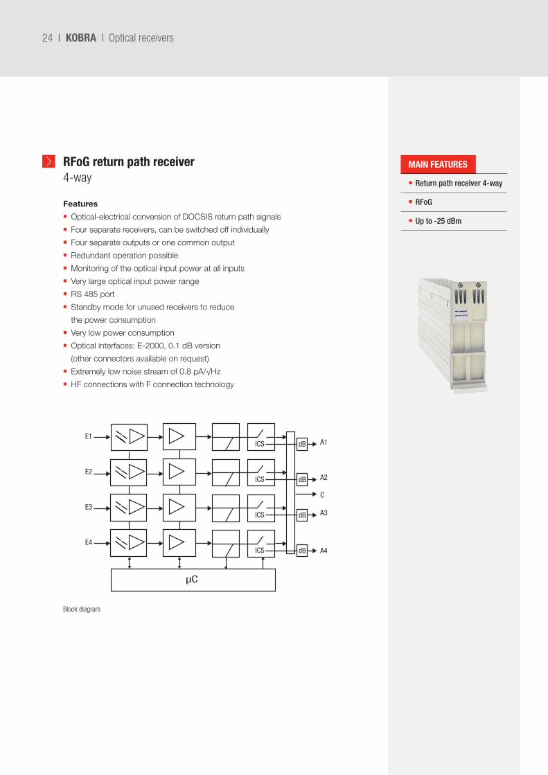
RFoG return path receiver4-way Return path receiver 4-way
RFoG
Up to -25 dBm
Features
Optical-electrical conversion of DOCSIS return path signals
Four separate receivers, can be switched off individually
Four separate outputs or one common output
Redundant operation possible
Monitoring of the optical input power at all inputs
Very large optical input power range
RS 485 port
Standby mode for unused receivers to reduce
the power consumption
Very low power consumption
Optical interfaces: E-2000, 0.1 dB version
(other connectors available on request)
Extremely low noise stream of 0.8 pA/√Hz
HF connections with F connection technology
KOBRA I Optical receivers
ICS dB
ICS dB
ICS dB
ICS dB
µC
E1
E2
E3
E4
A1
A2
C
A3
A4
Block diagram
MAIN FEATURES
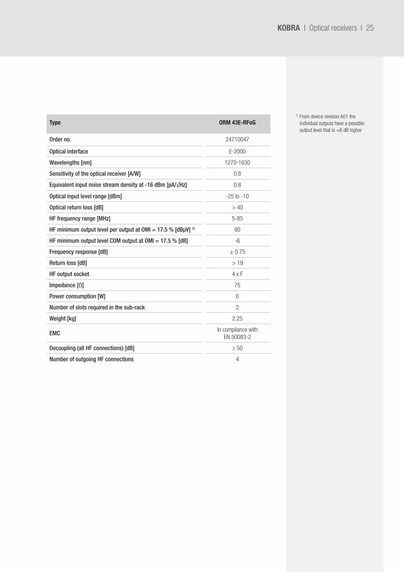
I 25
Type ORM 43E-RFoG
Order no. 24710047
Optical interface E-2000
Wavelengths [nm] 1270-1630
Sensitivity of the optical receiver [A/W] 0.8
Equivalent input noise stream density at -16 dBm [pA/√Hz] 0.8
Optical input level range [dBm] -25 to -10
Optical return loss [dB] > 40
HF frequency range [MHz] 5-85
HF minimum output level per output at OMI = 17.5 % [dBµV] ¹) 80
HF minimum output level COM output at OMI = 17.5 % [dB] -6
Frequency response [dB] ± 0.75
Return loss [dB] > 19
HF output socket 4 x F
Impedance [Ω] 75
Power consumption [W] 6
Number of slots required in the sub-rack 2
Weight [kg] 2.25
EMCIn compliance with
EN 50083-2
Decoupling (all HF connections) [dB] ≥ 50
Number of outgoing HF connections 4
1) From device revision A01 the individual outputs have a possible output level that is +6 dB higher
KOBRA I Optical receivers
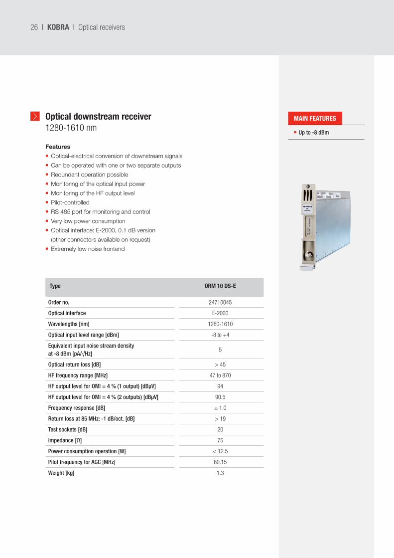
26 I
Optical downstream receiver1280-1610 nm Up to -8 dBm
Type ORM 10 DS-E
Order no. 24710045
Optical interface E-2000
Wavelengths [nm] 1280-1610
Optical input level range [dBm] -8 to +4
Equivalent input noise stream density at -8 dBm [pA/√Hz]
5
Optical return loss [dB] > 45
HF frequency range [MHz] 47 to 870
HF output level for OMI = 4 % (1 output) [dBµV] 94
HF output level for OMI = 4 % (2 outputs) [dBµV] 90.5
Frequency response [dB] ± 1.0
Return loss at 85 MHz: -1 dB/oct. [dB] > 19
Test sockets [dB] 20
Impedance [Ω] 75
Power consumption operation [W] < 12.5
Pilot frequency for AGC [MHz] 80.15
Weight [kg] 1.3
Features
Optical-electrical conversion of downstream signals
Can be operated with one or two separate outputs
Redundant operation possible
Monitoring of the optical input power
Monitoring of the HF output level
Pilot-controlled
RS 485 port for monitoring and control
Very low power consumption
Optical interface: E-2000, 0.1 dB version
(other connectors available on request)
Extremely low noise frontend
KOBRA I Optical receivers
MAIN FEATURES
I 27KOBRA I Optical amplifiers
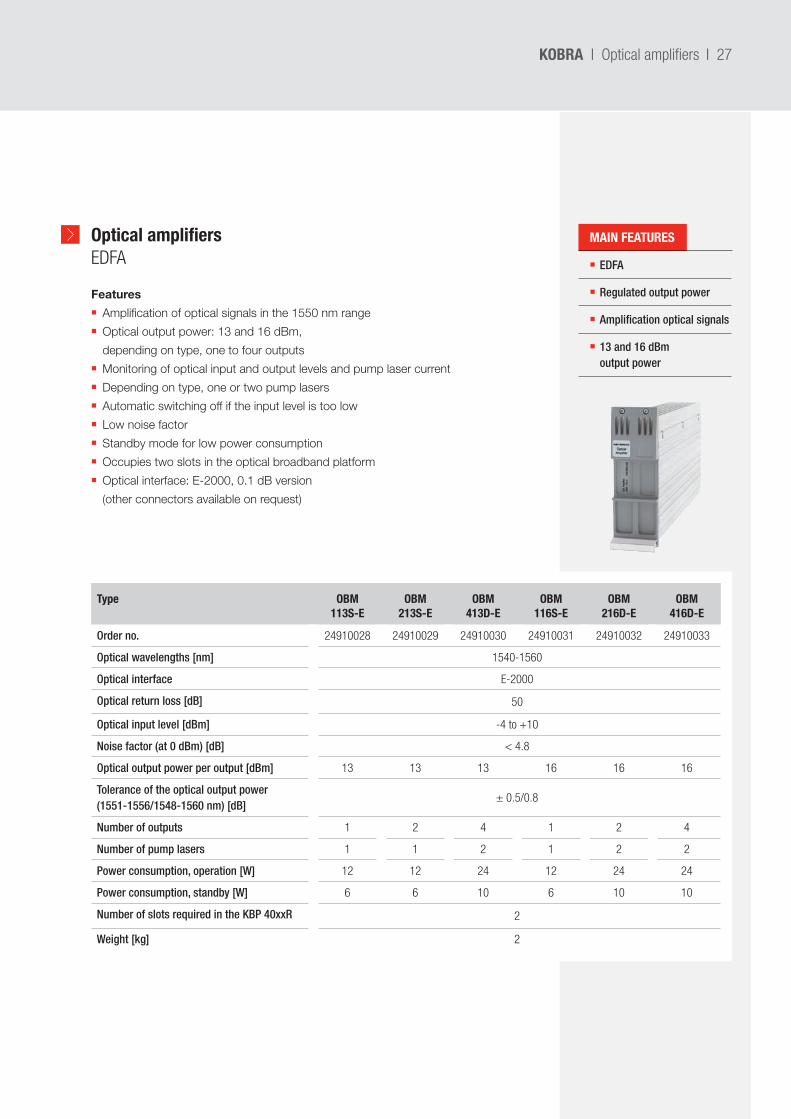
Optical amplifiers EDFA
Features
Amplification of optical signals in the 1550 nm range
Optical output power: 13 and 16 dBm,
depending on type, one to four outputs
Monitoring of optical input and output levels and pump laser current
Depending on type, one or two pump lasers
Automatic switching off if the input level is too low
Low noise factor
Standby mode for low power consumption
Occupies two slots in the optical broadband platform
Optical interface: E-2000, 0.1 dB version
(other connectors available on request)
EDFA
Regulated output power
Amplification optical signals
13 and 16 dBm output power
Type OBM 113S-E
OBM 213S-E
OBM 413D-E
OBM 116S-E
OBM 216D-E
OBM 416D-E
Order no. 24910028 24910029 24910030 24910031 24910032 24910033
Optical wavelengths [nm] 1540-1560
Optical interface E-2000
Optical return loss [dB] 50
Optical input level [dBm] -4 to +10
Noise factor (at 0 dBm) [dB] < 4.8
Optical output power per output [dBm] 13 13 13 16 16 16
Tolerance of the optical output power (1551-1556/1548-1560 nm) [dB]
± 0.5/0.8
Number of outputs 1 2 4 1 2 4
Number of pump lasers 1 1 2 1 2 2
Power consumption, operation [W] 12 12 24 12 24 24
Power consumption, standby [W] 6 6 10 6 10 10
Number of slots required in the KBP 40xxR 2
Weight [kg] 2
MAIN FEATURES
28 I KOBRA I Optical amplifiers
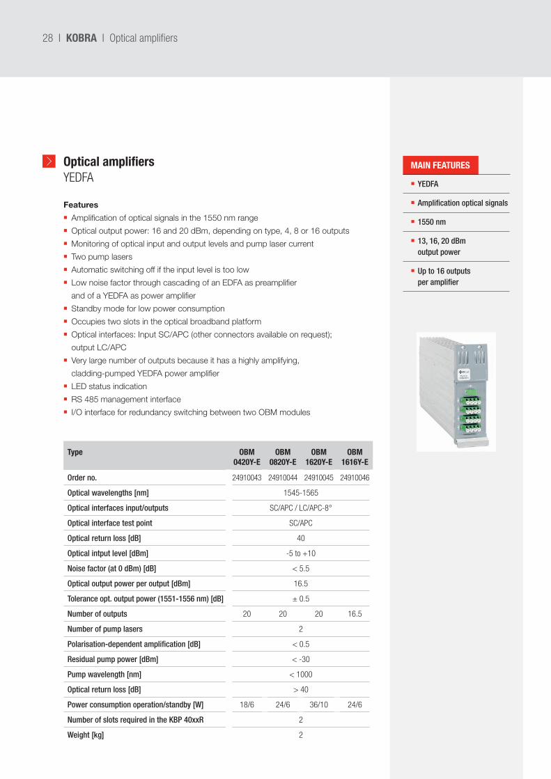
Optical amplifiersYEDFA YEDFA
Amplification optical signals
1550 nm
13, 16, 20 dBm output power
Up to 16 outputs per amplifier
Type OBM 0420Y-E
OBM 0820Y-E
OBM 1620Y-E
OBM 1616Y-E
Order no. 24910043 24910044 24910045 24910046
Optical wavelengths [nm] 1545-1565
Optical interfaces input/outputs SC/APC / LC/APC-8°
Optical interface test point SC/APC
Optical return loss [dB] 40
Optical intput level [dBm] -5 to +10
Noise factor (at 0 dBm) [dB] < 5.5
Optical output power per output [dBm] 16.5
Tolerance opt. output power (1551-1556 nm) [dB] ± 0.5
Number of outputs 20 20 20 16.5
Number of pump lasers 2
Polarisation-dependent amplification [dB] < 0.5
Residual pump power [dBm] < -30
Pump wavelength [nm] < 1000
Optical return loss [dB] > 40
Power consumption operation/standby [W] 18/6 24/6 36/10 24/6
Number of slots required in the KBP 40xxR 2
Weight [kg] 2
Features
Amplification of optical signals in the 1550 nm range
Optical output power: 16 and 20 dBm, depending on type, 4, 8 or 16 outputs
Monitoring of optical input and output levels and pump laser current
Two pump lasers
Automatic switching off if the input level is too low
Low noise factor through cascading of an EDFA as preamplifier
and of a YEDFA as power amplifier
Standby mode for low power consumption
Occupies two slots in the optical broadband platform
Optical interfaces: Input SC/APC (other connectors available on request);
output LC/APC
Very large number of outputs because it has a highly amplifying,
cladding-pumped YEDFA power amplifier
LED status indication
RS 485 management interface
I/O interface for redundancy switching between two OBM modules
MAIN FEATURES
I 29KOBRA I Other modules
Low insertion loss
Redundant switching
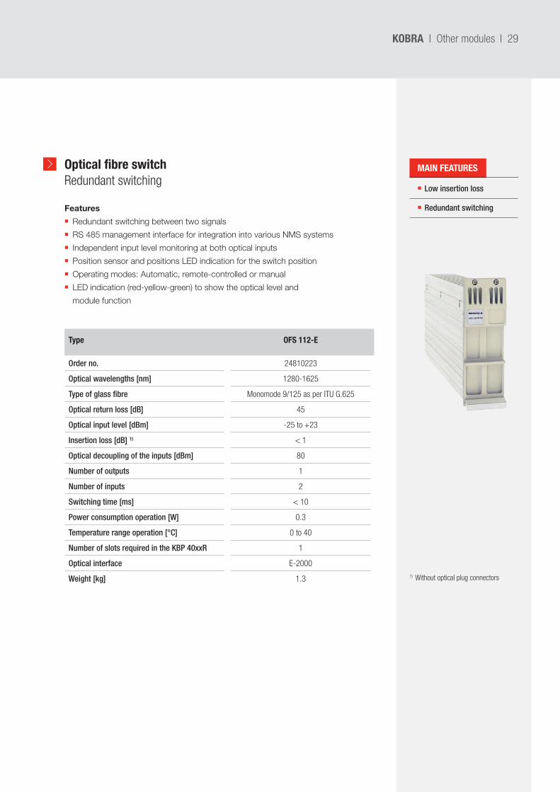
Type OFS 112-E
Order no. 24810223
Optical wavelengths [nm] 1280-1625
Type of glass fibre Monomode 9/125 as per ITU G.625
Optical return loss [dB] 45
Optical input level [dBm] -25 to +23
Insertion loss [dB] ¹) < 1
Optical decoupling of the inputs [dBm] 80
Number of outputs 1
Number of inputs 2
Switching time [ms] < 10
Power consumption operation [W] 0.3
Temperature range operation [°C] 0 to 40
Number of slots required in the KBP 40xxR 1
Optical interface E-2000
Weight [kg] 1.3
Optical fibre switch Redundant switching
Features
Redundant switching between two signals
RS 485 management interface for integration into various NMS systems
Independent input level monitoring at both optical inputs
Position sensor and positions LED indication for the switch position
Operating modes: Automatic, remote-controlled or manual
LED indication (red-yellow-green) to show the optical level and
module function
1) Without optical plug connectors
MAIN FEATURES
30 I KOBRA I Other modules
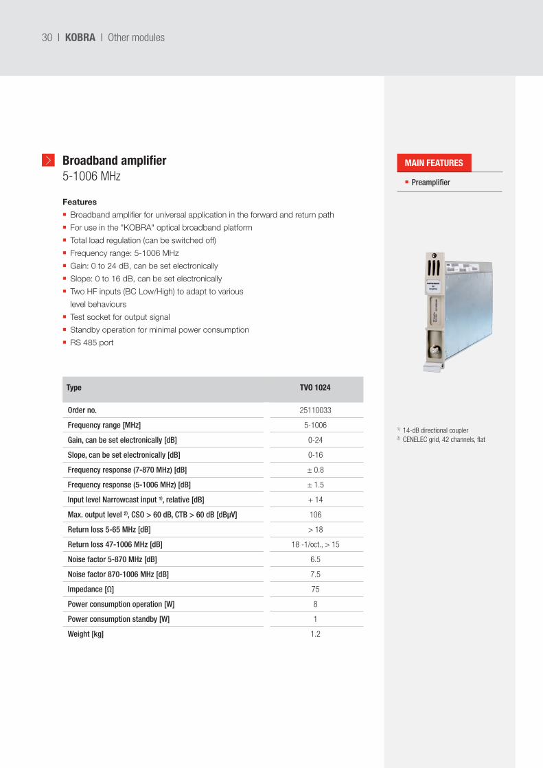
Broadband amplifier 5-1006 MHz
Type TVO 1024
Order no. 25110033
Frequency range [MHz] 5-1006
Gain, can be set electronically [dB] 0-24
Slope, can be set electronically [dB] 0-16
Frequency response (7-870 MHz) [dB] ± 0.8
Frequency response (5-1006 MHz) [dB] ± 1.5
Input level Narrowcast input ¹), relative [dB] + 14
Max. output level ²), CSO > 60 dB, CTB > 60 dB [dBµV] 106
Return loss 5-65 MHz [dB] > 18
Return loss 47-1006 MHz [dB] 18 -1/oct., > 15
Noise factor 5-870 MHz [dB] 6.5
Noise factor 870-1006 MHz [dB] 7.5
Impedance [Ω] 75
Power consumption operation [W] 8
Power consumption standby [W] 1
Weight [kg] 1.2
Features
Broadband amplifier for universal application in the forward and return path
For use in the "KOBRA" optical broadband platform
Total load regulation (can be switched off)
Frequency range: 5-1006 MHz
Gain: 0 to 24 dB, can be set electronically
Slope: 0 to 16 dB, can be set electronically
Two HF inputs (BC Low/High) to adapt to various
level behaviours
Test socket for output signal
Standby operation for minimal power consumption
RS 485 port
Preamplifier
1) 14-dB directional coupler2) CENELEC grid, 42 channels, flat
MAIN FEATURES
I 31KOBRA I 19" rack
19" 1 HU
YEDFA
Up to 20 dBm
Up to 16 outputs
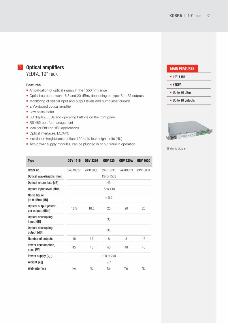
Optical amplifiers YEDFA, 19" rack
Type OBV 1616 OBV 3216 OBV 820 OBV 820W OBV 1620
Order no. 24910037 24910036 24910035 24910053 24910034
Optical wavelengths [nm] 1545-1565
Optical return loss [dB] 45
Optical input level [dBm] -5 to +10
Noise figure (at 0 dBm) [dB]
< 5.5
Optical output power per output [dBm]
16.5 16.5 20 20 20
Optical decoupling input [dB]
35
Optical decoupling output [dB]
35
Number of outputs 16 32 8 8 16
Power consumption, max. [W]
45 45 40 40 45
Power supply [VAC
] 100 to 240
Weight [kg] 9.7
Web interface No No No Yes No
Features
Amplification of optical signals in the 1550 nm range
Optical output power: 16.5 and 20 dBm, depending on type, 8 to 32 outputs
Monitoring of optical input and output levels and pump laser current
ErYb-doped optical amplifier
Low noise factor
LC display, LEDs and operating buttons on the front panel
RS 485 port for management
Ideal for FttH or HFC applications
Optical interfaces: LC/APC
Installation height/construction: 19" rack, four height units (HU)
Two power supply modules, can be plugged in or out while in operationSimilar to picture
MAIN FEATURES
32 I
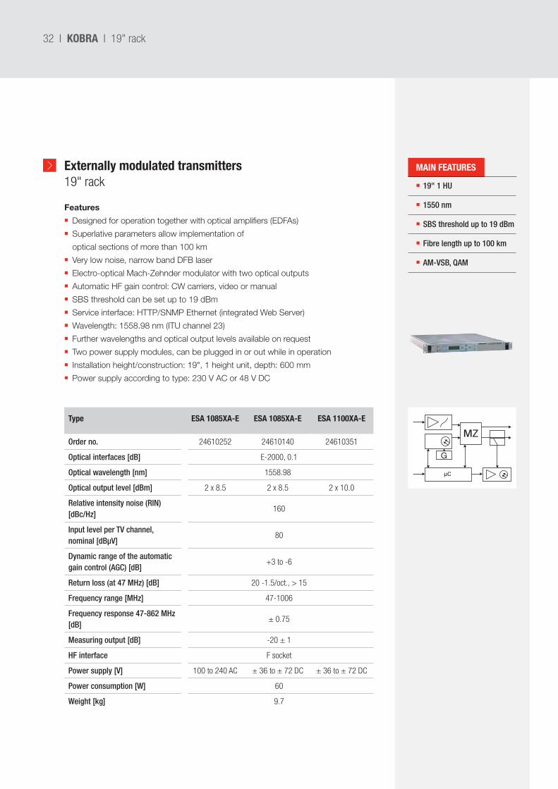
Externally modulated transmitters19" rack
19" 1 HU
1550 nm
SBS threshold up to 19 dBm
Fibre length up to 100 km
AM-VSB, QAM
Type ESA 1085XA-E ESA 1085XA-E ESA 1100XA-E
Order no. 24610252 24610140 24610351
Optical interfaces [dB] E-2000, 0.1
Optical wavelength [nm] 1558.98
Optical output level [dBm] 2 x 8.5 2 x 8.5 2 x 10.0
Relative intensity noise (RIN) [dBc/Hz]
160
Input level per TV channel, nominal [dBµV]
80
Dynamic range of the automatic gain control (AGC) [dB]
+3 to -6
Return loss (at 47 MHz) [dB] 20 -1.5/oct., > 15
Frequency range [MHz] 47-1006
Frequency response 47-862 MHz [dB]
± 0.75
Measuring output [dB] -20 ± 1
HF interface F socket
Power supply [V] 100 to 240 AC ± 36 to ± 72 DC ± 36 to ± 72 DC
Power consumption [W] 60
Weight [kg] 9.7
Features
Designed for operation together with optical amplifiers (EDFAs)
Superlative parameters allow implementation of
optical sections of more than 100 km
Very low noise, narrow band DFB laser
Electro-optical Mach-Zehnder modulator with two optical outputs
Automatic HF gain control: CW carriers, video or manual
SBS threshold can be set up to 19 dBm
Service interface: HTTP/SNMP Ethernet (integrated Web Server)
Wavelength: 1558.98 nm (ITU channel 23)
Further wavelengths and optical output levels available on request
Two power supply modules, can be plugged in or out while in operation
Installation height/construction: 19", 1 height unit, depth: 600 mm
Power supply according to type: 230 V AC or 48 V DC
KOBRA I 19" rack
µC
MZ
G
MAIN FEATURES

I 33KOBRA

9981
2497
/1/0
515/
VMPG
/PF
| Sub
ject
to c
hang
e.
KATHREIN-Werke KGAnton-Kathrein-Straße 1-383022 Rosenheim, GermanyPhone +49 8031 184-0Fax +49 8031 184-385www.kathrein.com | [email protected]


![Kobra sell sheet - JB Industries sell sheet[1].pdf · 2019. 8. 26. · WHY KOBRA HOSES ARE JUST BETTER THEN THE RESTWHY KOBRA HOSES ARE JUST BETTER THAN THE RESTWHY KOBRA HOSES ARE](https://img.pdfslide.us/doc/110x75/60c5473de7b319573f34960b/kobra-sell-sheet-jb-sell-sheet1pdf-2019-8-26-why-kobra-hoses-are-just.jpg)