Embed Size (px)
Citation preview
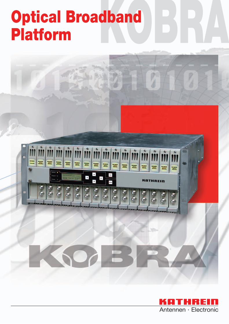
KOBRAOptical Broadband Platform
2
• Optical broadband platform for up to 16 modules
• Fitted with 2 redundant power supply and cooling fan units
• Wide selection of optical transmitters, amplifi ers and return path receivers
• All optical and electrical connections are located on the rear panel. Test sockets are on the front panel
• Can be integrated in every HMS-conform monitoring system
• Pluggable control panel with LC display, LEDs and input keys
• Tuning and management also via browser
• RS 485 remote monitoring and control interface
• Several optical broadband platforms can be managed using just one controller module
• Automatic redundant operation of adjacent modules
• High reliability due to dust-proof designed modules and large cooling ribs
• Models available for mains voltage (100 ... 240 VAC) and direct voltage (36 ... 72 VDC)
• Design: 19” racking, 4 rack units (RU)
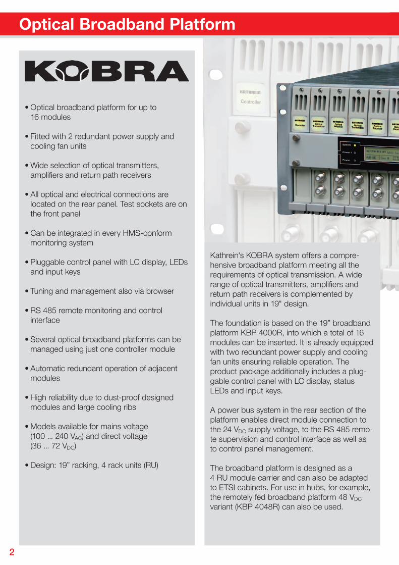
Kathrein's KOBRA system offers a compre-hensive broadband platform meeting all the requirements of optical transmission. A wide range of optical transmitters, amplifi ers and return path receivers is complemented by individual units in 19" design.
The foundation is based on the 19” broadbandplatform KBP 4000R, into which a total of 16 modules can be inserted. It is already equipped with two redundant power supply and cooling fan units ensuring reliable operation. Theproduct package additionally includes a plug-gable control panel with LC display, status LEDs and input keys.
A power bus system in the rear section of the platform enables direct module connection to the 24 VDC supply voltage, to the RS 485 remo-te supervision and control interface as well as to control panel management.
The broadband platform is designed as a 4 RU module carrier and can also be adapted to ETSI cabinets. For use in hubs, for example, the remotely fed broadband platform 48 VDC variant (KBP 4048R) can also be used.
Optical Broadband Platform
3
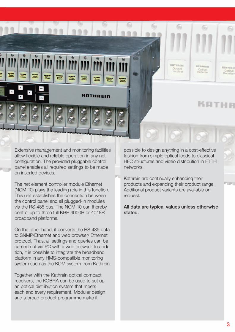
Extensive management and monitoring facilitiesallow fl exible and reliable operation in any net confi guration. The provided pluggable control panel enables all required settings to be made on inserted devices.
The net element controller module Ethernet (NCM 10) plays the leading role in this function.This unit establishes the connection between the control panel and all plugged-in modules via the RS 485 bus. The NCM 10 can thereby control up to three full KBP 4000R or 4048R broadband platforms.
On the other hand, it converts the RS 485 data to SNMP/Ethernet and web browser/ Ethernet protocol. Thus, all settings and queries can be carried out via PC with a web browser. In addi-tion, it is possible to integrate the broadband platform in any HMS-compatible monitoring system such as the KOM system from Kathrein.
Together with the Kathrein optical compactreceivers, the KOBRA can be used to set upan optical distribution system that meetseach and every requirement. Modular designand a broad product programme make it
possible to design anything in a cost-effective fashion from simple optical feeds to classical HFC structures and video distribution in FTTH networks.
Kathrein are continually enhancing theirproducts and expanding their product range.Additional product variants are available on request.
All data are typical values unless otherwise stated.
4
Functional and reliable - the optical broadband platform in detail
Gerät 16
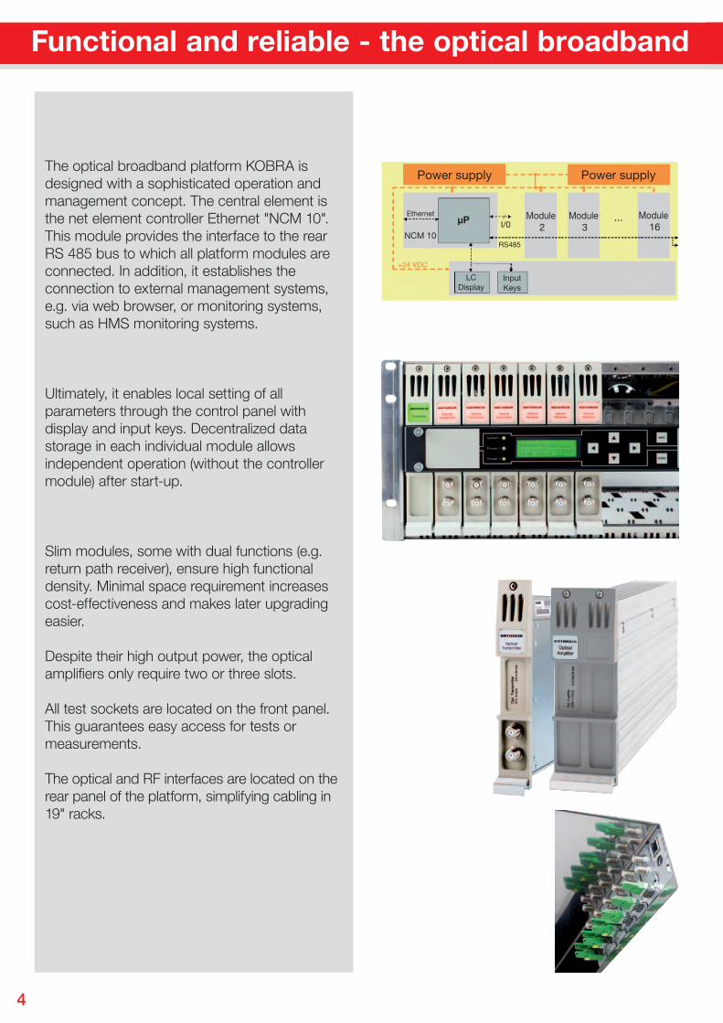
The optical broadband platform KOBRA is designed with a sophisticated operation and management concept. The central element is the net element controller Ethernet "NCM 10". This module provides the interface to the rear RS 485 bus to which all platform modules are connected. In addition, it establishes the connection to external management systems, e.g. via web browser, or monitoring systems, such as HMS monitoring systems.
Ultimately, it enables local setting of all parameters through the control panel with display and input keys. Decentralized data storage in each individual module allows independent operation (without the controller module) after start-up.
Slim modules, some with dual functions (e.g. return path receiver), ensure high functional density. Minimal space requirement increases cost-effectiveness and makes later upgrading easier.
Despite their high output power, the optical amplifiers only require two or three slots.
All test sockets are located on the front panel. This guarantees easy access for tests or measurements.
The optical and RF interfaces are located on the rear panel of the platform, simplifying cabling in 19" racks.
5
Functional and reliable - the optical broadband platform in detail
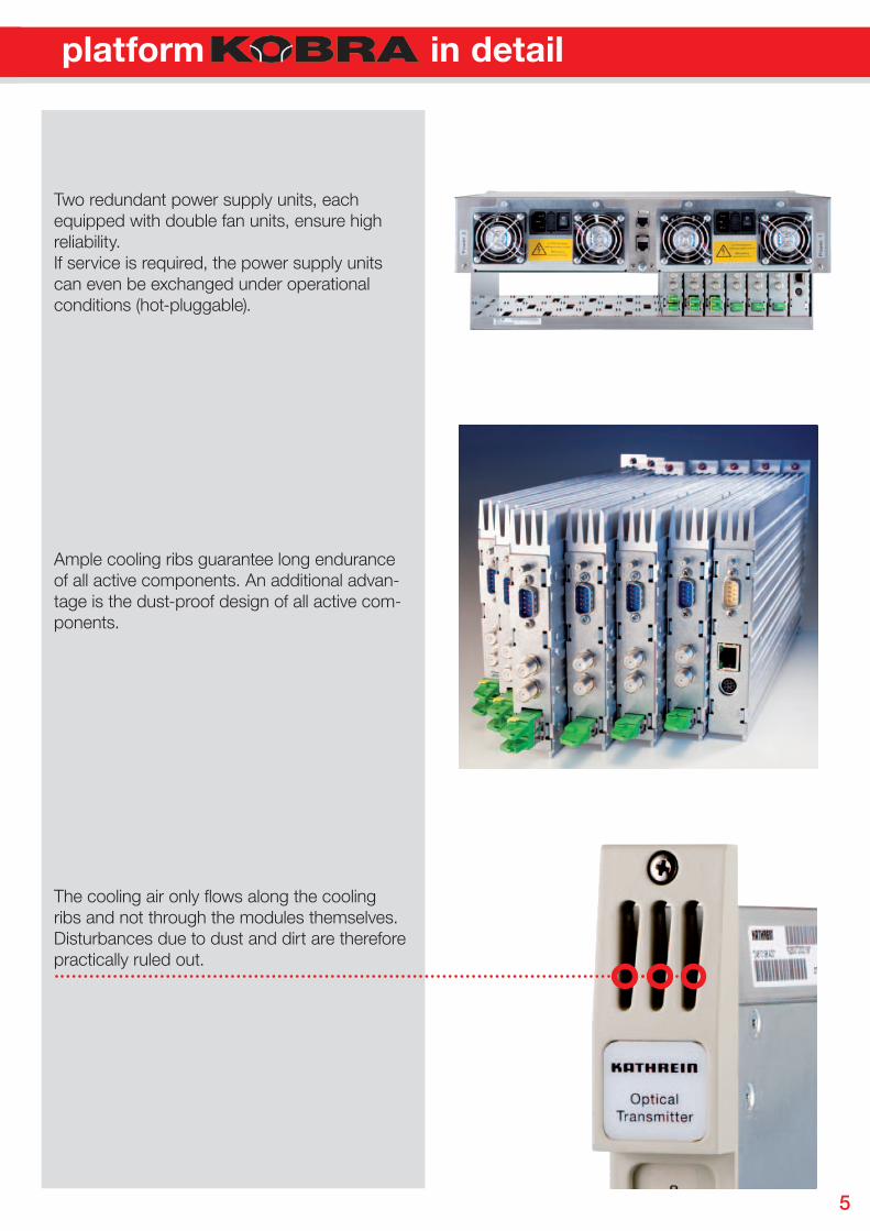
Two redundant power supply units, each equipped with double fan units, ensure highreliability. If service is required, the power supply units can even be exchanged under operationalconditions (hot-pluggable).
Ample cooling ribs guarantee long endurance of all active components. An additional advan-tage is the dust-proof design of all active com-ponents.
The cooling air only fl ows along the cooling ribs and not through the modules themselves. Disturbances due to dust and dirt are therefore practically ruled out.
Functional and reliable - the optical broadband platform in detailFunctional and reliable - the optical broadband platform in detailFunctional and reliable - the optical broadband platform in detail
6
19" Broadband platform for optical modules
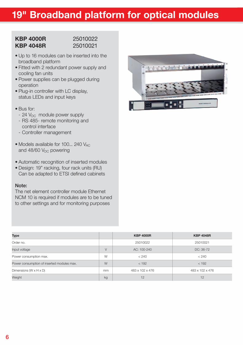
• Up to 16 modules can be inserted into the broadband platform• Fitted with 2 redundant power supply and cooling fan units• Power supplies can be plugged during operation• Plug-in controller with LC display, status LEDs and input keys
• Bus for: - 24 VDC module power supply - RS 485- remote monitoring and control interface - Controller management
• Models available for 100... 240 VAC and 48/60 VDC powering
• Automatic recognition of inserted modules• Design: 19” racking, four rack units (RU) Can be adapted to ETSI defi ned cabinets
Note:The net element controller module Ethernet NCM 10 is required if modules are to be tuned to other settings and for monitoring purposes
KBP 4000R 25010022KBP 4048R 25010021
Type KBP 4000R KBP 4048R
Order no. 25010022 25010021
Input voltage V AC: 100-240 DC: 36-72
Power consumption max. W < 240 < 240
Power consumption of inserted modules max. W < 192 < 192
Dimensions (W x H x D) mm 483 x 102 x 476 483 x 102 x 476
Weight kg 12 12
7
Net element controller module Ethernet
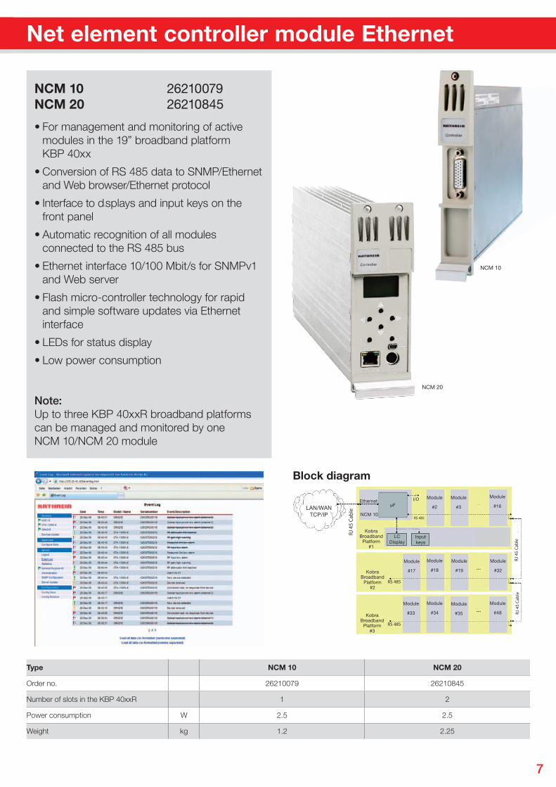
• For management and monitoring of active modules in the 19” broadband platform KBP 40xx
• Conversion of RS 485 data to SNMP/Ethernet and Web browser/Ethernet protocol
• Interface to displays and input keys on the front panel
• Automatic recognition of all modules connected to the RS 485 bus
• Ethernet interface 10/100 Mbit/s for SNMPv1 and Web server
• Flash micro-controller technology for rapid
and simple software updates via Ethernet interface
• LEDs for status display
• Low power consumption
Note:Up to three KBP 40xxR broadband platforms can be managed and monitored by one NCM 10/NCM 20 module
NCM 10 26210079NCM 20 26210845
LAN/WANTCP/IP
Ethernet
NCM 10
Module
#2
Module
#3
Module
#17
Module
#18
Module
#19
Module
#32
Module
#33
Module
#34
Module
#35
Module
#48
µP
RJ 4
5 Ca
ble
RJ 4
5 Ca
ble
RJ 4
5 Ca
ble
Module
#16
KobraBroadband
Platform#3
KobraBroadband
Platform#2
KobraBroadband
Platform#1
I/O
RS 485
RS 485
RS 485
Inputkeys
LCDisplay
NCM 10
NCM 20
Block diagram
Type NCM 10 NCM 20
Order no. 26210079 26210845
Number of slots in the KBP 40xxR 1 2
Power consumption W 2.5 2.5
Weight kg 1.2 2.25
8
Directly modulated broadcast transmitters, 1,310 nm, extremely linear
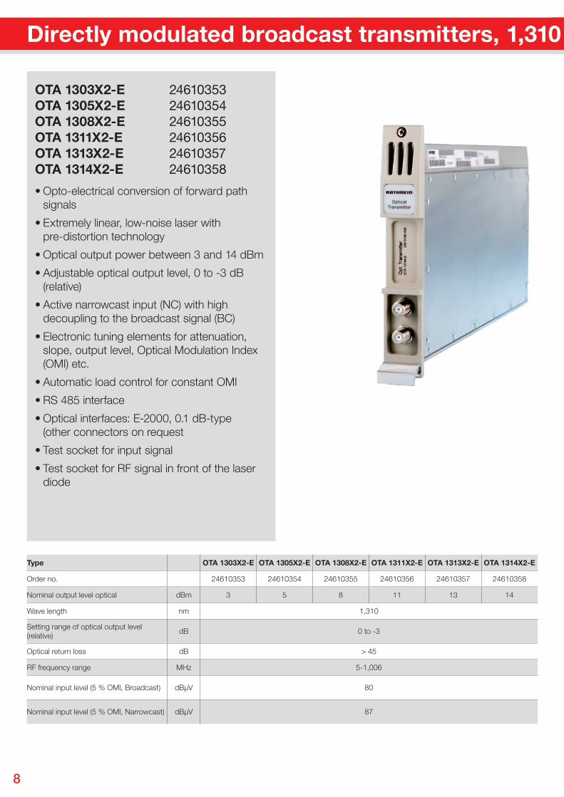
• Opto-electrical conversion of forward path signals
• Extremely linear, low-noise laser with pre-distortion technology
• Optical output power between 3 and 14 dBm
• Adjustable optical output level, 0 to -3 dB (relative)
• Active narrowcast input (NC) with high decoupling to the broadcast signal (BC)
• Electronic tuning elements for attenuation, slope, output level, Optical Modulation Index (OMI) etc.
• Automatic load control for constant OMI
• RS 485 interface
• Optical interfaces: E-2000, 0.1 dB-type (other connectors on request
• Test socket for input signal
• Test socket for RF signal in front of the laser diode
OTA 1303X2-E 24610353OTA 1305X2-E 24610354OTA 1308X2-E 24610355OTA 1311X2-E 24610356OTA 1313X2-E 24610357OTA 1314X2-E 24610358
Type OTA 1303X2-E OTA 1305X2-E OTA 1308X2-E OTA 1311X2-E OTA 1313X2-E OTA 1314X2-E
Order no. 24610353 24610354 24610355 24610356 24610357 24610358
Nominal output level optical dBm 3 5 8 11 13 14
Wave length nm 1,310
Setting range of optical output level (relative)
dB 0 to -3
Optical return loss dB > 45
RF frequency range MHz 5-1,006
Nominal input level (5 % OMI, Broadcast) dBµV 80
Nominal input level (5 % OMI, Narrowcast) dBµV 87
9
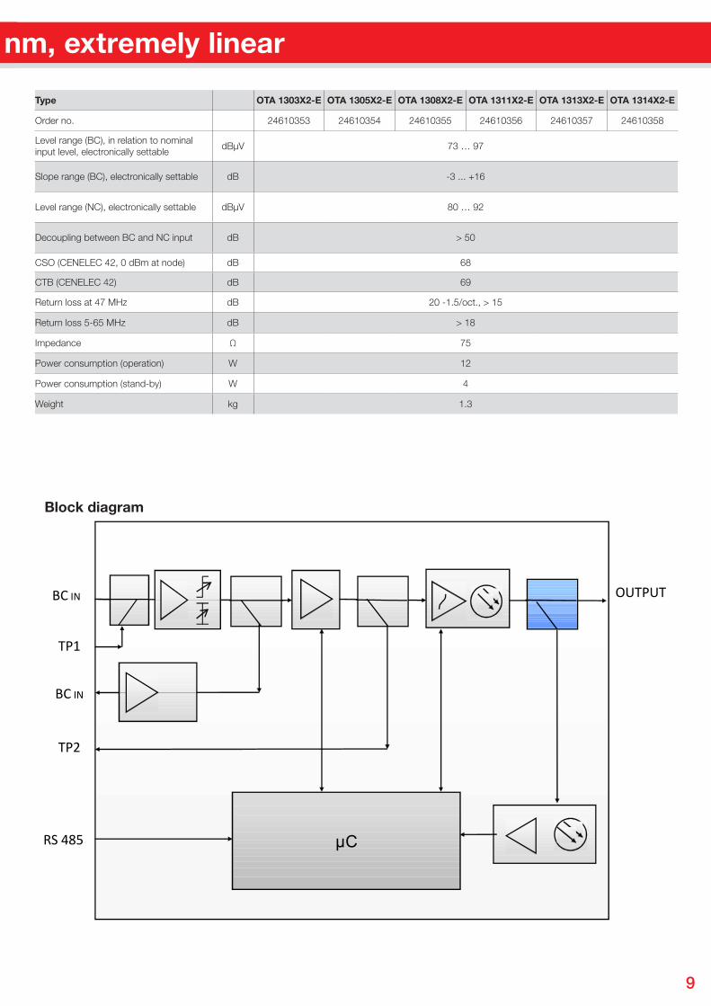
Directly modulated broadcast transmitters, 1,310 nm, extremely linear
µC
BC IN
TP1
TP2
OUTPUT
RS 485
BC IN
OTA 13xxX2, OTA 15xx
Type OTA 1303X2-E OTA 1305X2-E OTA 1308X2-E OTA 1311X2-E OTA 1313X2-E OTA 1314X2-E
Order no. 24610353 24610354 24610355 24610356 24610357 24610358
Level range (BC), in relation to nominal input level, electronically settable
dBµV 73 … 97
Slope range (BC), electronically settable dB -3 ... +16
Level range (NC), electronically settable dBµV 80 … 92
Decoupling between BC and NC input dB > 50
CSO (CENELEC 42, 0 dBm at node) dB 68
CTB (CENELEC 42) dB 69
Return loss at 47 MHz dB 20 -1.5/oct., > 15
Return loss 5-65 MHz dB > 18
Impedance Ω 75
Power consumption (operation) W 12
Power consumption (stand-by) W 4
Weight kg 1.3
Block diagram
10
Externally modulated transmitters
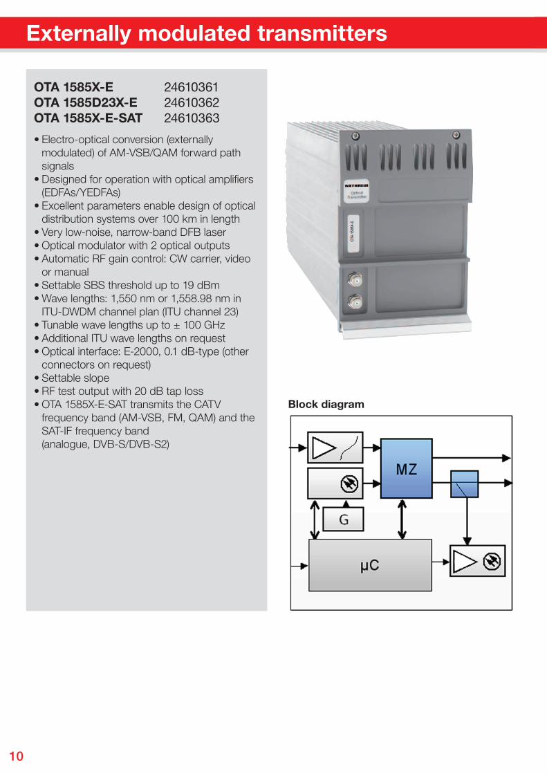
• Electro-optical conversion (externally modulated) of AM-VSB/QAM forward path signals• Designed for operation with optical amplifi ers (EDFAs/YEDFAs)• Excellent parameters enable design of optical distribution systems over 100 km in length• Very low-noise, narrow-band DFB laser • Optical modulator with 2 optical outputs• Automatic RF gain control: CW carrier, video or manual• Settable SBS threshold up to 19 dBm• Wave lengths: 1,550 nm or 1,558.98 nm in ITU-DWDM channel plan (ITU channel 23)• Tunable wave lengths up to ± 100 GHz• Additional ITU wave lengths on request • Optical interface: E-2000, 0.1 dB-type (other connectors on request)• Settable slope • RF test output with 20 dB tap loss • OTA 1585X-E-SAT transmits the CATV frequency band (AM-VSB, FM, QAM) and the SAT-IF frequency band (analogue, DVB-S/DVB-S2)
OTA 1585X-E 24610361OTA 1585D23X-E 24610362OTA 1585X-E-SAT 24610363
Block diagram
11
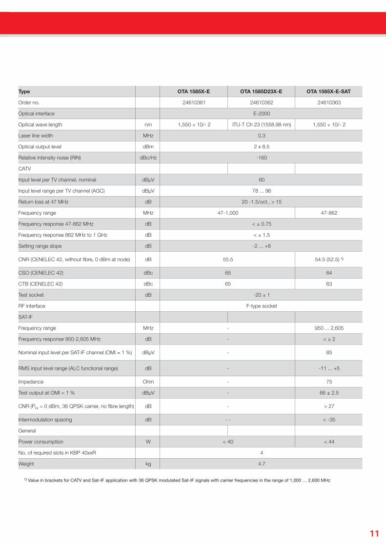
Type OTA 1585X-E OTA 1585D23X-E OTA 1585X-E-SAT
Order no. 24610361 24610362 24610363
Optical interface E-2000
Optical wave length nm 1,550 + 10/- 2 ITU-T Ch 23 (1558.98 nm) 1,550 + 10/- 2
Laser line width MHz 0.3
Optical output level dBm 2 x 8.5
Relative intensity noise (RIN) dBc/Hz -160
CATV
Input level per TV channel, nominal dBµV 80
Input level range per TV channel (AGC) dBµV 78 ... 96
Return loss at 47 MHz dB 20 -1.5/oct., > 15
Frequency range MHz 47-1,000 47-862
Frequency response 47-862 MHz dB < ± 0.75
Frequency response 862 MHz to 1 GHz dB < ± 1.5
Setting range slope dB -2 ... +8
CNR (CENELEC 42, without fibre, 0 dBm at node) dB 55.5 54.5 (52.5) ¹)
CSO (CENELEC 42) dBc 65 64
CTB (CENELEC 42) dBc 65 63
Test socket dB -20 ± 1
RF interface F-type socket
SAT-IF
Frequency range MHz - 950 ... 2,605
Frequency response 950-2,605 MHz dB - < ± 2
Nominal input level per SAT-IF channel (OMI = 1 %) dBµV - 85
RMS input level range (ALC functional range) dB - -11 ... +5
Impedance Ohm - 75
Test output at OMI = 1 % dBµV - 66 ± 2.5
CNR (Prx = 0 dBm, 36 QPSK carrier, no fibre length) dB - > 27
Intermodulation spacing dB - - < -35
General
Power consumption W < 40 < 44
No. of required slots in KBP 40xxR 4
Weight kg 4.7
¹) Value in brackets for CATV and Sat-IF application with 36 QPSK modulated Sat-IF signals with carrier frequencies in the range of 1,000 … 2,600 MHz
12
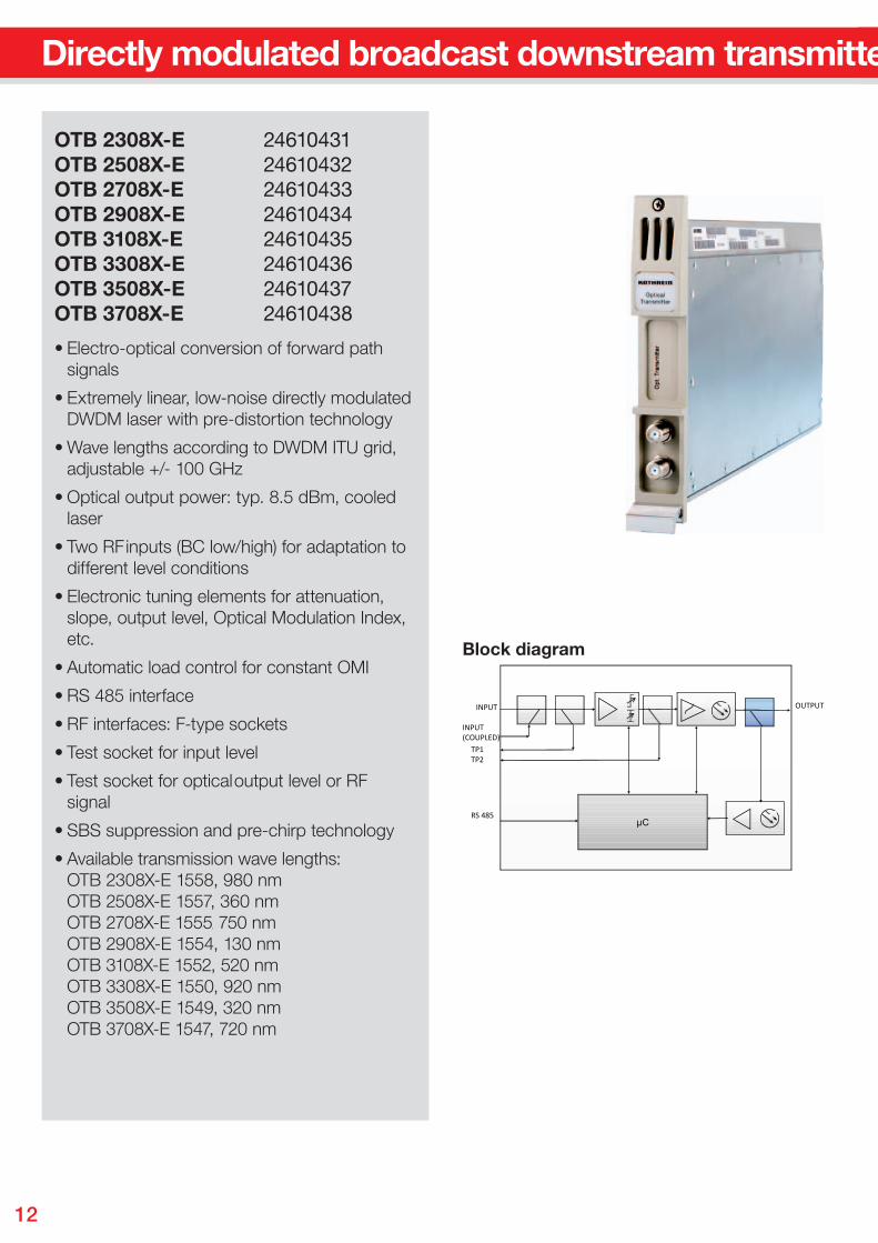
Directly modulated broadcast downstream transmitters, DWDM
• Electro-optical conversion of forward path signals
• Extremely linear, low-noise directly modulated DWDM laser with pre-distortion technology
• Wave lengths according to DWDM ITU grid, adjustable +/- 100 GHz
• Optical output power: typ. 8.5 dBm, cooled laser
• Two RF inputs (BC low/high) for adaptation to different level conditions
• Electronic tuning elements for attenuation, slope, output level, Optical Modulation Index, etc.
• Automatic load control for constant OMI
• RS 485 interface
• RF interfaces: F-type sockets
• Test socket for input level
• Test socket for optical output level or RF signal
• SBS suppression and pre-chirp technology
• Available transmission wave lengths: OTB 2308X-E 1558, 980 nm OTB 2508X-E 1557, 360 nm OTB 2708X-E 1555, 750 nm OTB 2908X-E 1554, 130 nm OTB 3108X-E 1552, 520 nm OTB 3308X-E 1550, 920 nm OTB 3508X-E 1549, 320 nm OTB 3708X-E 1547, 720 nm
OTB 2308X-E 24610431OTB 2508X-E 24610432OTB 2708X-E 24610433OTB 2908X-E 24610434OTB 3108X-E 24610435OTB 3308X-E 24610436OTB 3508X-E 24610437OTB 3708X-E 24610438
µC
INPUT
INPUT(COUPLED)
TP1TP2
OUTPUT
RS 485
OTN, OTSBlock diagram
13
Directly modulated broadcast downstream transmitters, DWDM
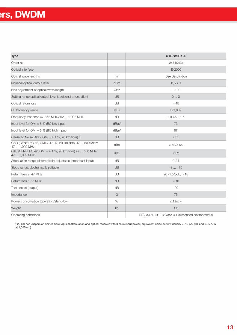
Type OTB xx08X-E
Order no. 2461043x
Optical interface E-2000
Optical wave lengths nm See description
Nominal optical output level dBm 8,5 ± 1
Fine adjustment of optical wave length GHz ± 100
Setting range optical output level (additional attenuation) dB 0 ... 3
Optical return loss dB > 45
RF frequency range MHz 5-1,002
Frequency response 47-862 MHz/862 ... 1,002 MHz dB ± 0.75/± 1.5
Input level for OMI = 5 % (BC low input) dBµV 73
Input level for OMI = 5 % (BC high input) dBµV 87
Carrier to Noise Ratio (OMI = 4.1 %, 20 km fibre) ¹) dB ≥ 51
CSO (CENELEC 42, OMI = 4.1 %, 20 km fibre) 47 ... 600 MHz/ 47 ... 1,002 MHz
dBc ≥ 60/≥ 55
CTB (CENELEC 42, OMI = 4.1 %, 20 km fibre) 47 ... 600 MHz/ 47 ... 1,002 MHz
dBc ≥ 62
Attenuation range, electronically adjustable (broadcast input) dB 0-24
Slope range, electronically settable dB -3 ... +16
Return loss at 47 MHz dB 20 -1.5/oct., > 15
Return loss 5-65 MHz dB > 18
Test socket (output) dB -20
Impedance Ω 75
Power consumption (operation/stand-by) W ≤ 12/≤ 4
Weight kg 1.3
Operating conditions ETSI 300 019-1-3 Class 3.1 (climatised environments)
¹) 20 km non-dispersion shifted fibre, optical attenuation and optical receiver with 0 dBm input power, equivalent noise current density = 7.0 pA/√Hz and 0.95 A/W (at 1,550 nm)
14
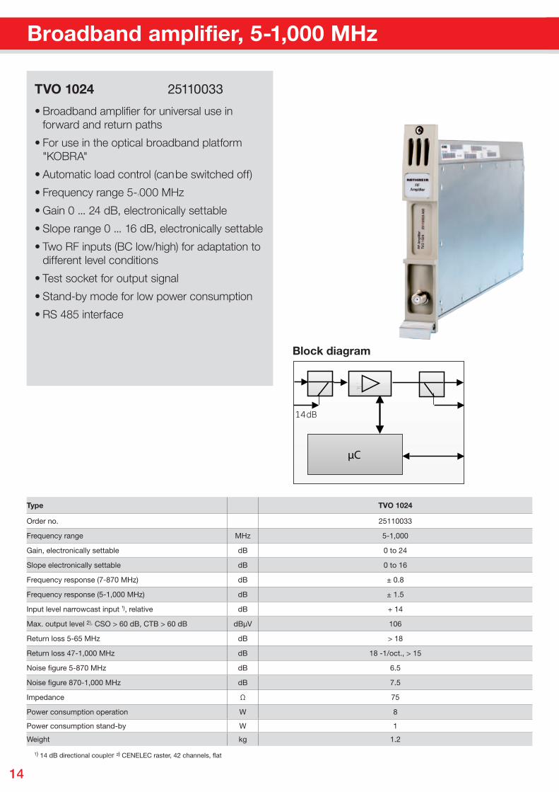
• Broadband amplifier for universal use in forward and return paths
• For use in the optical broadband platform "KOBRA"
• Automatic load control (can be switched off)
• Frequency range 5-1000 MHz
• Gain 0 ... 24 dB, electronically settable
• Slope range 0 ... 16 dB, electronically settable
• Two RF inputs (BC low/high) for adaptation to different level conditions
• Test socket for output signal
• Stand-by mode for low power consumption
• RS 485 interface
TVO 1024 25110033
¹) 14 dB directional coupler ²) CENELEC raster, 42 channels, flat
Type TVO 1024
Order no. 25110033
Frequency range MHz 5-1,000
Gain, electronically settable dB 0 to 24
Slope electronically settable dB 0 to 16
Frequency response (7-870 MHz) dB ± 0.8
Frequency response (5-1,000 MHz) dB ± 1.5
Input level narrowcast input ¹), relative dB + 14
Max. output level 2), CSO > 60 dB, CTB > 60 dB dBµV 106
Return loss 5-65 MHz dB > 18
Return loss 47-1,000 MHz dB 18 -1/oct., > 15
Noise figure 5-870 MHz dB 6.5
Noise figure 870-1,000 MHz dB 7.5
Impedance Ω 75
Power consumption operation W 8
Power consumption stand-by W 1
Weight kg 1.2
Broadband amplifier, 5-1,000 MHz
Pete
r Wan
del H
T, 0
8/20
09
µC
14dB
Block diagram
15
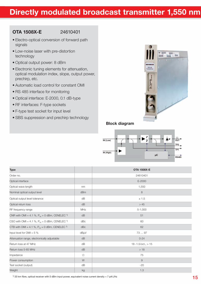
Directly modulated broadcast transmitter 1,550 nm
• Electro-optical conversion of forward path signals
• Low-noise laser with pre-distortion technology
• Optical output power: 8 dBm
• Electronic tuning elements for attenuation, optical modulation index, slope, output power, prechirp, etc.
• Automatic load control for constant OMI
• RS 485 interface for monitoring
• Optical interface: E-2000, 0.1 dB-type
• RF interfaces: F-type sockets
• F-type test socket for input level
• SBS suppression and prechirp technology
OTA 1508X-E 24610401
Type OTA 1508X-E
Order no. 24610401
Optical interface E-2000
Optical wave length nm 1,550
Nominal optical output level dBm 8
Optical output level tolerance dB ± 1.5
Optical return loss dB > 45
RF frequency range MHz 5-1,000
CNR with OMI = 4.1 %, Prx = 0 dBm, CENELEC ¹) dB 51
CSO with OMI = 4.1 %, Prx = 0 dBm, CENELEC ¹) dBc 60
CTB with OMI = 4.1 %, Prx = 0 dBm, CENELEC ¹) dBc 62
Input level for OMI = 5 % dBµV 73 … 97
Attenuation range, electronically adjustable dB 0-24
Return loss at 47 MHz dB 18 -1.5/oct., > 15
Return loss 5-65 MHz dB > 18
Impedance Ω 75
Power consumption W 9
Test socket (output) dB -20
Weight kg 1.3
¹) 20 km fibre, optical receiver with 0 dBm input power, equivalent noise current density = 7 pA/√Hz
Block diagram
16
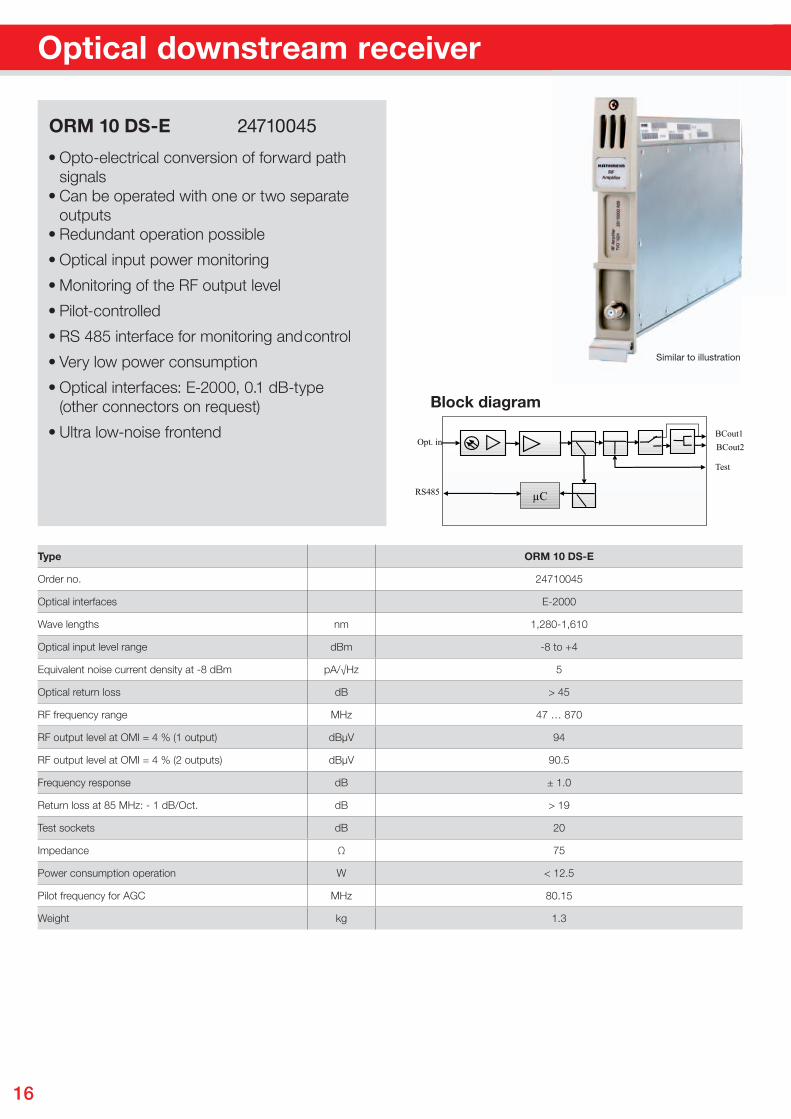
Optical downstream receiver
• Opto-electrical conversion of forward path signals• Can be operated with one or two separate outputs• Redundant operation possible
• Optical input power monitoring
• Monitoring of the RF output level
• Pilot-controlled
• RS 485 interface for monitoring and control
• Very low power consumption
• Optical interfaces: E-2000, 0.1 dB-type (other connectors on request)
• Ultra low-noise frontend
ORM 10 DS-E 24710045
Type ORM 10 DS-E
Order no. 24710045
Optical interfaces E-2000
Wave lengths nm 1,280-1,610
Optical input level range dBm -8 to +4
Equivalent noise current density at -8 dBm pA/√Hz 5
Optical return loss dB > 45
RF frequency range MHz 47 … 870
RF output level at OMI = 4 % (1 output) dBµV 94
RF output level at OMI = 4 % (2 outputs) dBµV 90.5
Frequency response dB ± 1.0
Return loss at 85 MHz: - 1 dB/Oct. dB > 19
Test sockets dB 20
Impedance Ω 75
Power consumption operation W < 12.5
Pilot frequency for AGC MHz 80.15
Weight kg 1.3
Similar to illustration
µC
Opt. inBCout1BCout2
Test
RS485
Block diagram
17
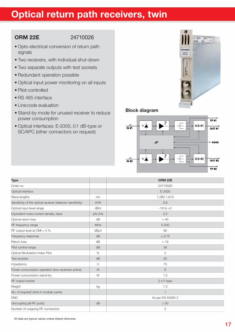
Similar to illustration
• Opto-electrical conversion of return path signals
• Two receivers, with individual shut-down
• Two separate outputs with test sockets
• Redundant operation possible
• Optical input power monitoring on all inputs
• Pilot-controlled
• RS 485 interface
• Line code evaluation
• Stand-by mode for unused receiver to reduce power consumption
• Optical interfaces: E-2000, 0.1 dB-type or SC/APC (other connectors on request)
ORM 22E 24710026
Optical return path receivers, twin
IN #1
OR265-nn
OUT #1
TP #1
µP RS485
ICS #1
IN #2 OUT #2
TP #2
ICS #2
IN #1 OUT #1
TP #1
µP RS485
ICS #1
IN #2 OUT #2
TP #2
ICS #2
Block diagram
Type ORM 22E
Order no. 24710026
Optical interface E-2000
Wave lengths nm 1,280-1,610
Sensitivity of the optical receiver (detector sensitivity) A/W 0.8
Optical input level range dBm -16 to +2
Equivalent noise current density, input pA/√Hz 2.5
Optical return loss dB > 40
RF frequency range MHz 5-200
RF output level at OMI = 5 % dBµV 90
Frequency response dB ± 0.75
Return loss dB > 19
Pilot control range dB 36
Optical Modulation Index Pilot % 5
Test sockets dB 20
Impedance Ω 75
Power consumption operation (two receivers active) W 6
Power consumption stand-by W 1.5
RF output socket 2 x F-type
Weight kg 1.3
No. of required slots in module carrier 1
EMC As per EN 50083-2
Decoupling (all RF ports) dB ≥ 50
Number of outgoing RF connectors 2
All data are typical values unless stated otherwise.
18
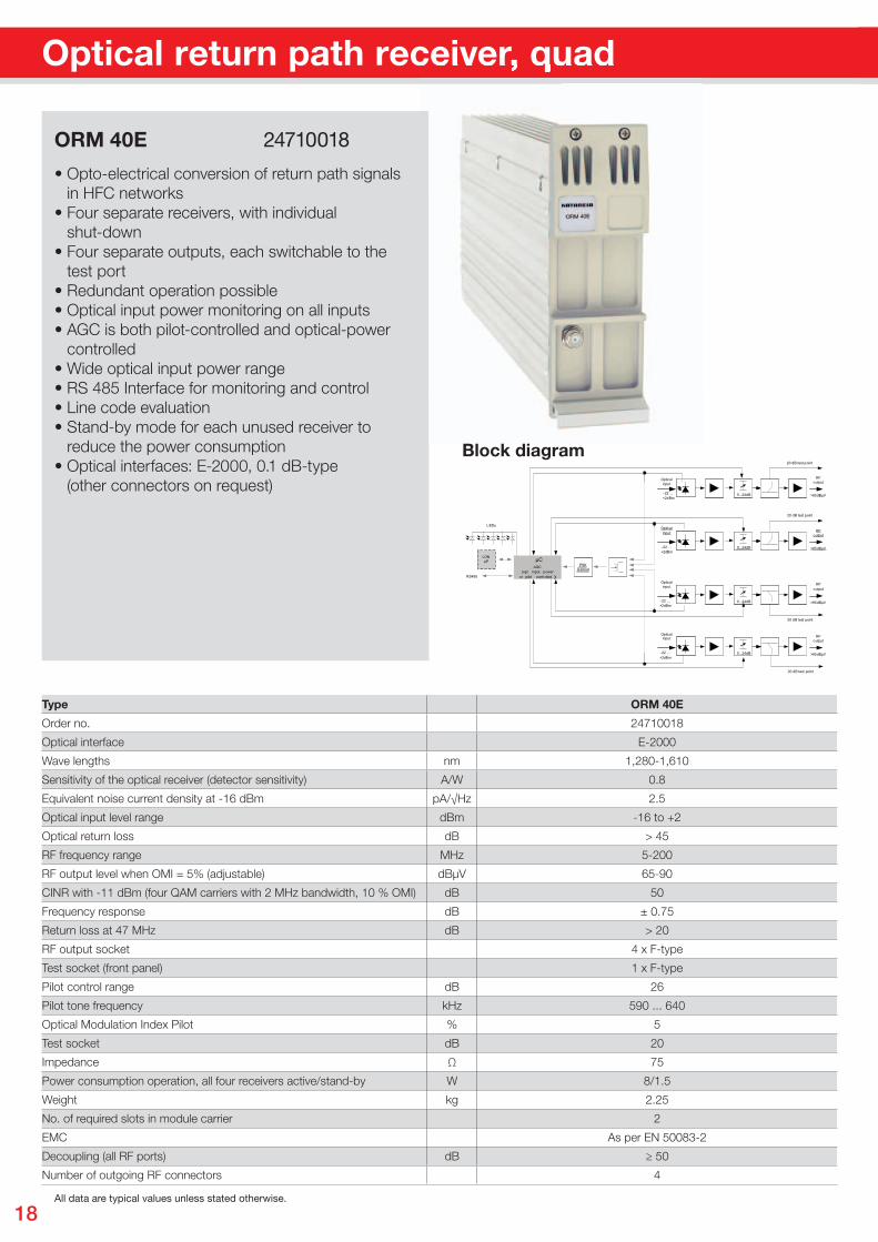
Optical return path receiver, quad
• Opto-electrical conversion of return path signals in HFC networks• Four separate receivers, with individual shut-down• Four separate outputs, each switchable to the test port• Redundant operation possible• Optical input power monitoring on all inputs• AGC is both pilot-controlled and optical-power controlled• Wide optical input power range• RS 485 Interface for monitoring and control• Line code evaluation• Stand-by mode for each unused receiver to reduce the power consumption• Optical interfaces: E-2000, 0.1 dB-type (other connectors on request)
ORM 40E 24710018
Optical return path receiver, quad
Opticalinput
-22 ...+2dBm
0...10dB0...10dB0...24dB
RFoutput
>85dBµV
Opticalinput
0...10dB0...10dB0...24dB
RFoutput
>85dBµV
Opticalinput
0...10dB0...10dB0...24dB
RFoutput
>85dBµV
Opticalinput
0...10dB0...10dB0...24dB
RFoutput
>85dBµV
AGC(opt. input power
or pilot controlled )))
µC
-22 ...+2dBm
-22 .. .+2dBm
-22 .. .+2dBm
PSKDemod
LONµP
LEDs
RS485
20 dB test point
20 dB test point
20 dB test point
20 dB test point
Block diagram
Type ORM 40E
Order no. 24710018
Optical interface E-2000
Wave lengths nm 1,280-1,610
Sensitivity of the optical receiver (detector sensitivity) A/W 0.8
Equivalent noise current density at -16 dBm pA/√Hz 2.5
Optical input level range dBm -16 to +2
Optical return loss dB > 45
RF frequency range MHz 5-200
RF output level when OMI = 5% (adjustable) dBµV 65-90
CINR with -11 dBm (four QAM carriers with 2 MHz bandwidth, 10 % OMI) dB 50
Frequency response dB ± 0.75
Return loss at 47 MHz dB > 20
RF output socket 4 x F-type
Test socket (front panel) 1 x F-type
Pilot control range dB 26
Pilot tone frequency kHz 590 ... 640
Optical Modulation Index Pilot % 5
Test socket dB 20
Impedance Ω 75
Power consumption operation, all four receivers active/stand-by W 8/1.5
Weight kg 2.25
No. of required slots in module carrier 2
EMC As per EN 50083-2
Decoupling (all RF ports) dB ≥ 50
Number of outgoing RF connectors 4
All data are typical values unless stated otherwise.
19
Similar to illustra-tion
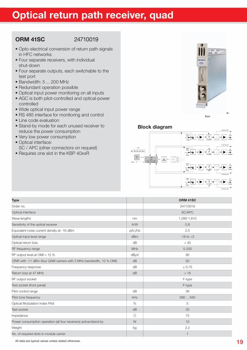
Type ORM 41SC
Order no. 24710019
Optical interface SC/APC
Wave lengths nm 1,280-1,610
Sensitivity of the optical receiver A/W 0.8
Equivalent noise current density at -16 dBm pA/√Hz 2.5
Optical input level range dBm -18 to +2
Optical return loss dB > 45
RF frequency range MHz 5-200
RF output level at OMI = 15 % dBµV 95
CINR with -11 dBm (four QAM carriers with 2 MHz bandwidth, 10 % OMI) dB 50
Frequency response dB ± 0.75
Return loss at 47 MHz dB > 16
RF output socket F-type
Test socket (front panel) F-type
Pilot control range dB 36
Pilot tone frequency kHz 590 ... 640
Optical Modulation Index Pilot % 5
Test socket dB 20
Impedance Ω 75
Power consumption operation (all four receivers) active/stand-by W 10
Weight kg 2.2
No. of required slots in module carrier 1
All data are typical values unless stated otherwise.
Optical return path receiver, quad
• Opto-electrical conversion of return path signals in HFC networks• Four separate receivers, with individual shut-down• Four separate outputs, each switchable to the test port• Bandwidth: 5 ... 200 MHz• Redundant operation possible• Optical input power monitoring on all inputs• AGC is both pilot-controlled and optical-power controlled• Wide optical input power range • RS 485 interface for monitoring and control• Line code evaluation• Stand-by mode for each unused receiver to reduce the power consumption• Very low power consumption• Optical interface: SC / APC (other connectors on request)• Requires one slot in the KBP 40xxR
ORM 41SC 24710019
Opticalinput
-22 ...+2dBm
0...10dB0...10dB0...24dB
RFoutput
>85dBµV
Opticalinput
0...10dB0...10dB0...24dB
RFoutput
>85dBµV
Opticalinput
0...10dB0...10dB0...24dB
RFoutput
>85dBµV
Opticalinput
0...10dB0...10dB0...24dB
RFoutput
>85dBµV
AGC(opt. input power
or pilot controlled )))
µC
-22 ...+2dBm
-22 .. .+2dBm
-22 .. .+2dBm
PSKDemod
LONµP
LEDs
RS485
20 dB test point
20 dB test point
20 dB test point
20 dB test point
Block diagram
20
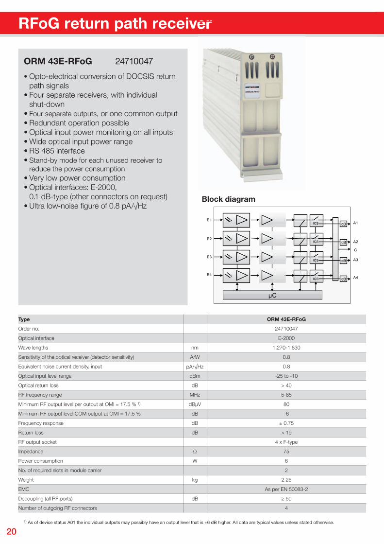
RFoG return path receiver
• Opto-electrical conversion of DOCSIS return path signals• Four separate receivers, with individual shut-down• Four separate outputs, or one common output• Redundant operation possible• Optical input power monitoring on all inputs• Wide optical input power range• RS 485 interface• Stand-by mode for each unused receiver to reduce the power consumption• Very low power consumption• Optical interfaces: E-2000, 0.1 dB-type (other connectors on request)• Ultra low-noise fi gure of 0.8 pA/√Hz
ORM 43E-RFoG 24710047
RFoG return path receiver
µC
ICS
ICS
ICS
ICS
E1
E2
E3
E4
A1
A2
A3
A4
C
dB
dB
dB
dB
Block diagram
Type ORM 43E-RFoG
Order no. 24710047
Optical interface E-2000
Wave lengths nm 1,270-1,630
Sensitivity of the optical receiver (detector sensitivity) A/W 0.8
Equivalent noise current density, input pA/√Hz 0.8
Optical input level range dBm -25 to -10
Optical return loss dB > 40
RF frequency range MHz 5-85
Minimum RF output level per output at OMI = 17.5 % ¹) dBµV 80
Minimum RF output level COM output at OMI = 17.5 % dB -6
Frequency response dB ± 0.75
Return loss dB > 19
RF output socket 4 x F-type
Impedance Ω 75
Power consumption W 6
No. of required slots in module carrier 2
Weight kg 2.25
EMC As per EN 50083-2
Decoupling (all RF ports) dB ≥ 50
Number of outgoing RF connectors 4
¹) As of device status A01 the individual outputs may possibly have an output level that is +6 dB higher. All data are typical values unless stated otherwise.
21
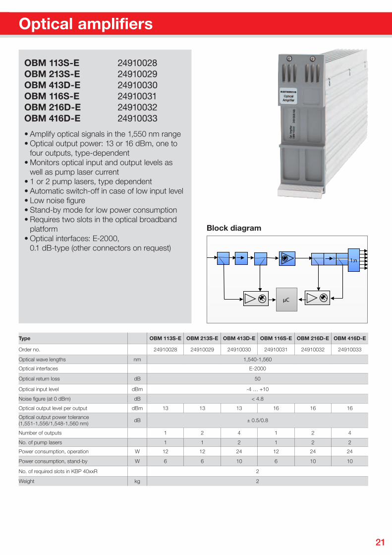
OBM 113S-E 24910028OBM 213S-E 24910029OBM 413D-E 24910030OBM 116S-E 24910031OBM 216D-E 24910032OBM 416D-E 24910033
• Amplify optical signals in the 1,550 nm range• Optical output power: 13 or 16 dBm, one to four outputs, type-dependent• Monitors optical input and output levels as well as pump laser current• 1 or 2 pump lasers, type dependent• Automatic switch-off in case of low input level• Low noise figure• Stand-by mode for low power consumption• Requires two slots in the optical broadband platform• Optical interfaces: E-2000, 0.1 dB-type (other connectors on request)
Optical amplifiers
Type OBM 113S-E OBM 213S-E OBM 413D-E OBM 116S-E OBM 216D-E OBM 416D-E
Order no. 24910028 24910029 24910030 24910031 24910032 24910033
Optical wave lengths nm 1,540-1,560
Optical interfaces E-2000
Optical return loss dB 50
Optical input level dBm -4 … +10
Noise figure (at 0 dBm) dB < 4.8
Optical output level per output dBm 13 13 13 16 16 16
Optical output power tolerance(1,551-1,556/1,548-1,560 nm)
dB ± 0.5/0.8
Number of outputs 1 2 4 1 2 4
No. of pump lasers 1 1 2 1 2 2
Power consumption, operation W 12 12 24 12 24 24
Power consumption, stand-by W 6 6 10 6 10 10
No. of required slots in KBP 40xxR 2
Weight kg 2
Pete
r Wan
del H
T, 0
8/20
09
1:n
µC
Block diagram
22
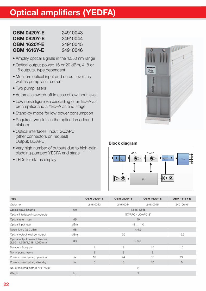
Optical amplifiers (YEDFA)
OBM 0420Y-E 24910043OBM 0820Y-E 24910044OBM 1620Y-E 24910045OBM 1616Y-E 24910046
• Amplify optical signals in the 1,550 nm range
• Optical output power: 16 or 20 dBm, 4, 8 or 16 outputs, type dependent
• Monitors optical input and output levels as well as pump laser current
• Two pump lasers
• Automatic switch-off in case of low input level
• Low noise fi gure via cascading of an EDFA as preamplifi er and a YEDFA as end stage
• Stand-by mode for low power consumption
• Requires two slots in the optical broadband platform
• Optical interfaces: Input: SC/APC (other connectors on request) Output: LC/APC
• Very high number of outputs due to high-gain, cladding-pumped YEDFA end stage
• LEDs for status display
Type OBM 0420Y-E OBM 0820Y-E OBM 1620Y-E OBM 1616Y-E
Order no. 24910043 24910044 24910045 24910046
Optical wave lengths nm 1,545-1,565
Optical interfaces input/outputs SC/APC / LC/APC-8°
Optical return loss dB 40
Optical input level dBm -5 … +10
Noise figure (at 0 dBm) dB < 5.5
Optical output level per output dBm 20 16.5
Optical output power tolerance (1,551-1,556/1,548-1,560 nm)
dB ± 0.5
Number of outputs 4 8 16 16
No. of pump lasers 2 2 2 1
Power consumption, operation W 18 24 36 24
Power consumption, stand-by W 6 6 10 6
No. of required slots in KBP 40xxR 2
Weight kg 2
Pete
r Wan
del H
T, 0
8/20
09
1:n
µC
YEDFAEDFA
Block diagram
23
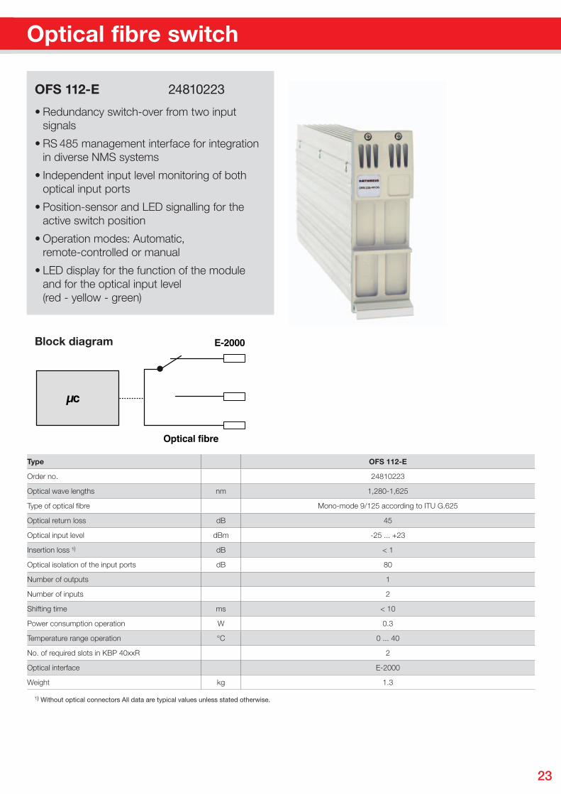
• Redundancy switch-over from two input signals
• RS 485 management interface for integration in diverse NMS systems
• Independent input level monitoring of both optical input ports
• Position-sensor and LED signalling for the active switch position
• Operation modes: Automatic, remote-controlled or manual
• LED display for the function of the module and for the optical input level (red - yellow - green)
OFS 112-E 24810223
µPµc
E-2000
Optical fibre
Optical fibre switch
Type OFS 112-E
Order no. 24810223
Optical wave lengths nm 1,280-1,625
Type of optical fi bre Mono-mode 9/125 according to ITU G.625
Optical return loss dB 45
Optical input level dBm -25 ... +23
Insertion loss ¹) dB < 1
Optical isolation of the input ports dB 80
Number of outputs 1
Number of inputs 2
Shifting time ms < 10
Power consumption operation W 0.3
Temperature range operation °C 0 ... 40
No. of required slots in KBP 40xxR 2
Optical interface E-2000
Weight kg 1.3
¹) Without optical connectors All data are typical values unless stated otherwise.
Block diagram
24
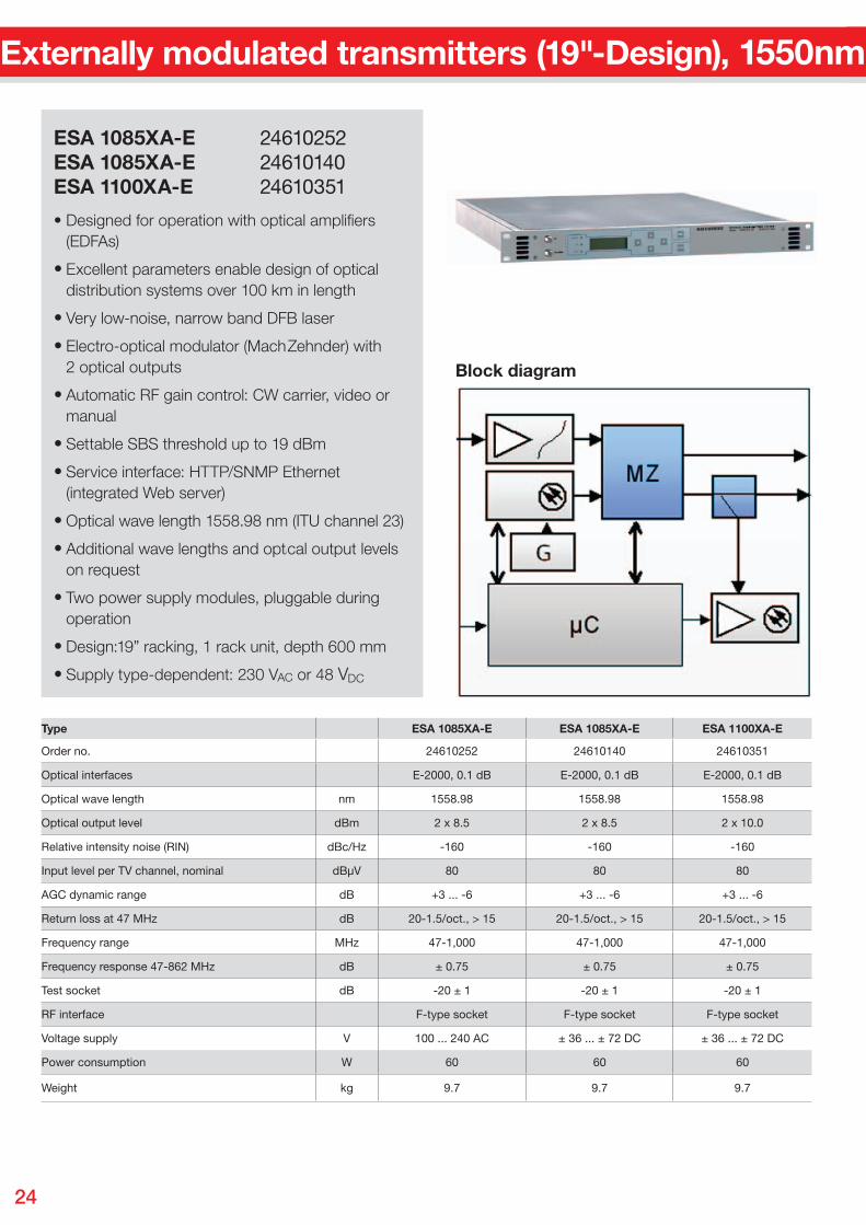
Externally modulated transmitters (19"-Design), 1550nm
• Designed for operation with optical amplifi ers (EDFAs)
• Excellent parameters enable design of optical distribution systems over 100 km in length
• Very low-noise, narrow band DFB laser
• Electro-optical modulator (Mach Zehnder) with 2 optical outputs
• Automatic RF gain control: CW carrier, video or manual
• Settable SBS threshold up to 19 dBm
• Service interface: HTTP/SNMP Ethernet (integrated Web server)
• Optical wave length 1558.98 nm (ITU channel 23)
• Additional wave lengths and optical output levels on request
• Two power supply modules, pluggable during operation
• Design:19” racking, 1 rack unit, depth 600 mm
• Supply type-dependent: 230 VAC or 48 VDC
ESA 1085XA-E 24610252ESA 1085XA-E 24610140ESA 1100XA-E 24610351
Type ESA 1085XA-E ESA 1085XA-E ESA 1100XA-E
Order no. 24610252 24610140 24610351
Optical interfaces E-2000, 0.1 dB E-2000, 0.1 dB E-2000, 0.1 dB
Optical wave length nm 1558.98 1558.98 1558.98
Optical output level dBm 2 x 8.5 2 x 8.5 2 x 10.0
Relative intensity noise (RIN) dBc/Hz -160 -160 -160
Input level per TV channel, nominal dBµV 80 80 80
AGC dynamic range dB +3 ... -6 +3 ... -6 +3 ... -6
Return loss at 47 MHz dB 20-1.5/oct., > 15 20-1.5/oct., > 15 20-1.5/oct., > 15
Frequency range MHz 47-1,000 47-1,000 47-1,000
Frequency response 47-862 MHz dB ± 0.75 ± 0.75 ± 0.75
Test socket dB -20 ± 1 -20 ± 1 -20 ± 1
RF interface F-type socket F-type socket F-type socket
Voltage supply V 100 ... 240 AC ± 36 ... ± 72 DC ± 36 ... ± 72 DC
Power consumption W 60 60 60
Weight kg 9.7 9.7 9.7
Block diagram
25
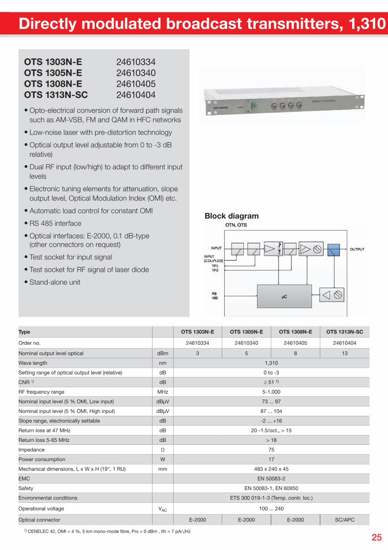
OTS 1303N-E 24610334OTS 1305N-E 24610340OTS 1308N-E 24610405OTS 1313N-SC 24610404
Type OTS 1303N-E OTS 1305N-E OTS 1308N-E OTS 1313N-SC
Order no. 24610334 24610340 24610405 24610404
Nominal output level optical dBm 3 5 8 13
Wave length nm 1,310
Setting range of optical output level (relative) dB 0 to -3
CNR ¹) dB ≥ 51 1)
RF frequency range MHz 5-1,000
Nominal input level (5 % OMI, Low input) dBµV 73 ... 97
Nominal input level (5 % OMI, High input) dBµV 87 ... 104
Slope range, electronically settable dB -2 ... +16
Return loss at 47 MHz dB 20 -1.5/oct., > 15
Return loss 5-65 MHz dB > 18
Impedance Ω 75
Power consumption W 17
Mechanical dimensions, L x W x H (19", 1 RU) mm 483 x 240 x 45
EMC EN 50083-2
Safety EN 50083-1, EN 60950
Environmental conditions ETS 300 019-1-3 (Temp. contr. loc.)
Operational voltage VAC 100 ... 240
Optical connector E-2000 E-2000 E-2000 SC/APC
¹) CENELEC 42, OMI = 4 %, 5 km mono-mode fi bre, Prx = 0 dBm , Ith = 7 pA/√Hz
Directly modulated broadcast transmitters, 1,310 nm
• Opto-electrical conversion of forward path signals such as AM-VSB, FM and QAM in HFC networks
• Low-noise laser with pre-distortion technology
• Optical output level adjustable from 0 to -3 dB relative)
• Dual RF input (low/high) to adapt to different input levels
• Electronic tuning elements for attenuation, slope, output level, Optical Modulation Index (OMI) etc.
• Automatic load control for constant OMI
• RS 485 interface
• Optical interfaces: E-2000, 0.1 dB-type (other connectors on request)
• Test socket for input signal
• Test socket for RF signal of laser diode
• Stand-alone unit
Block diagram
26
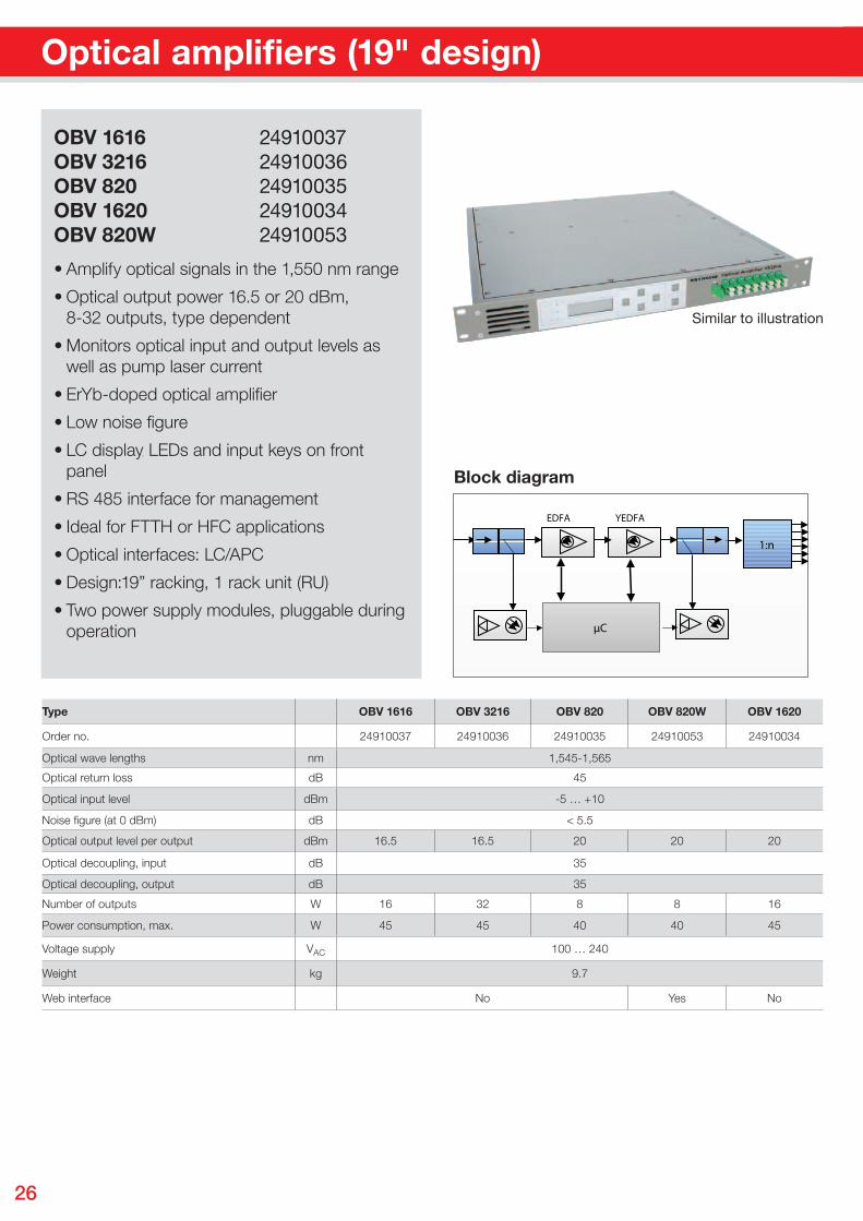
OBV 1616 24910037OBV 3216 24910036OBV 820 24910035OBV 1620 24910034OBV 820W 24910053
• Amplify optical signals in the 1,550 nm range
• Optical output power 16.5 or 20 dBm, 8-32 outputs, type dependent
• Monitors optical input and output levels as well as pump laser current
• ErYb-doped optical amplifi er
• Low noise fi gure
• LC display, LEDs and input keys on front panel
• RS 485 interface for management
• Ideal for FTTH or HFC applications
• Optical interfaces: LC/APC
• Design:19” racking, 1 rack unit (RU)
• Two power supply modules, pluggable during operation
Type OBV 1616 OBV 3216 OBV 820 OBV 820W OBV 1620
Order no. 24910037 24910036 24910035 24910053 24910034
Optical wave lengths nm 1,545-1,565
Optical return loss dB 45
Optical input level dBm -5 … +10
Noise figure (at 0 dBm) dB < 5.5
Optical output level per output dBm 16.5 16.5 20 20 20
Optical decoupling, input dB 35
Optical decoupling, output dB 35
Number of outputs W 16 32 8 8 16
Power consumption, max. W 45 45 40 40 45
Voltage supply VAC 100 … 240
Weight kg 9.7
Web interface No Yes No
Optical amplifiers (19" design)
Similar to illustration
Pete
r Wan
del H
T, 0
8/20
09
1:n
µC
YEDFAEDFA
Block diagram

27
Optical amplifiers (19" design) Notes

We are always pleased to be able to advise you:99
8122
84/1
/051
4/V
M/P
f
Tech
nica
l dat
a su
bje
ct t
o ch
ange
.
KATHREIN-Werke KG · Phone +49 8031 184-0 · Fax +49 8031 184-385 Anton-Kathrein-Str. 1 - 3 · P. O. Box 10 04 44 · 83004 Rosenheim · GERMANY
www.kathrein.de · [email protected]
The products described must only be installed by qualified specialists.Please consult the provided instruction manuals for safety instructions that are to be considered during use. All data are typical values unless otherwise stated.