Embed Size (px)
Citation preview
IntroductionELAN’s VSE100 is an electronic 12 step stereo Volume Control with Variable Impedance Match settings of 1X, 2X, and 4X designed for use with ampli-fiers of up to 100 Watts output. The VSE100 features an IR receiver which passes IR data to other sources as well as accepting IR information from remote controls or other IR devices. The VSE100 also features an IR input so that external controllers (Z•Pad Keypads, VIA!® Color LCD Touchpanels, etc.) can be hard wired to this device without using an IR emitter. Additionally, the VSE100 features ELAN’s patented Page/Doorbell Override to work with ELAN communication controllers such as the Z•600. Impedance Match adjustments allow multiple pairs of speakers to be connected to the same amplifier channels without damaging the amplifier.
Features• High-Power Capability: Handles up to 100 Watts RMS.
• Override: Allows Page/Doorbell signals to override the music at a pre-set level even with volume turned all the way down or with the VSE100 in Mute.
• Impedance Matching (1X/2X/4X): Allows multiple speaker pairs to be connected to a single pair of amplifier channels.
• IR In/Out: A built-in IR receiver allows the VSE100 to be controlled from , universal remotes, keypads, VIA! Color LCD Touch Screen, or out-board IR receiver. IR can be sent to the VSE100 using an IR emitter or through the RJ45 jack on the rear of the unit. IR can be sent from the IR output to source equipment, IR distribution networks or whole-house controllers.
• Sense Input: This option determines if a High to Low level transition on the Sense Input mutes the VSE100’s volume. When voltage drops to a Low level, the VSE100 mutes. The transition to High voltage level DOES NOT un-mute the VSE100, however. A physical button press is required to un-mute this device. This allows the system or zone to be turned on without all of the VSE100s in the system playing audio. Each VSE100 will turn on when the Zone or System turns on, but they will all be muted. When con-necting to ELAN S6 or S12 systems, the Sense Input feature can be used for either zone-specific or system-wide detection. ELAN Z systems provide system On/Off detection only. This feature can be disabled.
• Sleep Mode: Allows automatic muting of the VSE100 after a specified period of time (ten minutes, thirty minutes, one hour, or two hours).
• Talkback LED: LED Indicator flashes when IR activity is received through the built-in IR receiver. This feature can be disabled.
• Default Volume: This option guards against high volume un-mutes. Determines maximum turn on volume level when an IR VOLUME UP com-mand is sent. This feature can be disabled.
• On Default Volume Check: This option determines if the Default Volume is used as the maximum level, when the VSE100 is un-muted by an IR ON Command. This feature can be disabled.
• Code Grouping: Allows independent control of VSEs connected to the same IR wiring.
• Preset Volume Levels: Eleven preset levels allow user to obtain a specified volume level with one button press.
• Programmable Volume Jumps: Adjustable rate of volume increment when using Volume Level Presets allows for Fast Ramping, Slow Ramping, or Instant (no ramping).
• Variable Speed Ramping: Volume Up speed depends on volume level. As the volume level reaches higher levels, the speed of volume ramp-ing decreases. This feature can be disabled.
InstallationRough-inThe VSE100 fits into most 18 cu. in. rough-in boxes and P-rings. P-rings allow the best access and depth and should be used where local building codes allow. DO NOT install the VSE100 in the same electrical box as high-voltage (110VAC) devices such as dimmers, light switches, etc. as these devices will cause harmful interference and create buzzing, humming, or other audio interference. Close proximity to high-voltage devices can also cause undesired IR operation.
Like any IR device, the VSE100’s IR receiver is susceptible to interference from ambient light, sunlight, or plasma television radiation. Please do not mount the unit in locations susceptible to these conditions.
Note: The VSE100 is not warranted for outdoor installation.
WiringFour-conductor speaker wire and Cat-5 cable should be run from the main equipment location where the system’s amplifier is located to the mounting location for each VSE100. The speaker terminals on this unit will accom-modate 14 to 24 AWG stranded copper speaker wire. Runs that exceed 150 feet should use heavier gauge wire, but 16 or 18 AWG is usually suf-ficient. Check local building codes for specific guidelines regarding in-wall wire runs. Cat-5 cable is required when installing this unit to provide Power, Override, Sense Input, IR In, and IR Out. This unit must be connected to power in order to function.
BlueWh/BlueOrangeWh/OrangeGreenWh/GreenBrownWh/Brown
12345678
TAB
FR
ON
T
CABLE
OverrideIR OutIR InN/CN/C+12VDCGroundSense
VSE100 PIN ASSIGNMENT
RJ45
AM
PLI
FIE
RS
PE
AK
ER
L+ L
-R
- R
+L+
L-
R-
R+
To Speakers
FromAmplifier
Cat-5
Impedance Match Jumper
Impedance Match Jumper
5
Turning the VSE100 ON (VSE100 Volume level LEDs are OFF.)
1. Press the MUTE button on the VSE100. 2. Press ON on the supplied remote. 3. Issue any ELAN Source Select IR command. Note: When the VSE100 is turned ON using any of the above methods, the Volume level is restored to the last setting before the VSE100 was turned OFF.
4. Press the VOLUME UP button on the VSE100. 5. Press VOLUME UP on the supplied remote. 6. Issue any ELAN VOLUME UP IR command.
Note: When the VSE100 is turned ON using any of the above methods, theVolume level is restored to the last setting before the VSE100 was OFF but no higher than the OVERRIDE Volume level setting.
7. Press the VOLUME DOWN button on the VSE100 8. Press VOLUME DOWN on the supplied remote. 9. Issue any ELAN VOLUME DOWN command.
Note: When the VSE100 is turned ON using any of the above methods, theVolume level is set to the lowest audible level.
Turning the VSE100 OFF (The VSE100 Volume level LEDs are ON.) 1. Press the MUTE button on the VSE100. 2. Press OFF button on the supplied remote. 3. Issue any ELAN SYSTEM OFF command.
Controlling Volume 1. Press VOLUME UP or VOLUME DOWN buttons on the VSE100. 2. Press VOLUME UP or VOLUME DOWN buttons on the included remote control. 3. Issue a VSE VOLUME UP or VOLUME DOWN command from a key pad, VIA! Touch Panel, hand-held remote, or third-party controller (IR commands are located in VIA!TOOLS IR Library).
NOTE: The VSE100 will respond to VSE VOLUME UP/DOWN commands found in the VIA!®TOOLS IR Library or from the supplied remote. The sup-plied EVCR remote can be used to teach other learning remotes when nec-essary.
Muting the Volume 1. Press the MUTE button on the VSE100. 2. Press the MUTE button on an ELAN remote control. 3. Issue any ELAN MUTE command.
VSE100 HIGH POWER ELECTRONIC STEREO VOLUME CONTROL w/ OVERRIDE & IR SENSOR
SERIES
®
Series III
www.elanhomesystems.com 2428 Palumbo Dr Lexington, KY 40509
®
P/N 9900821 REV: A
DO NOT REVERSE AMPLIFIER AND
SPEAKER CONNECTIONS!!
Sense Input ConnectionsIf the Sense Input feature is being used, the VSE100 will mute when volt-age drops to a Low level but does not un-mute when voltage returns to a high level. The VSE100 will turn on in a muted state This allows the system or zone to be turned on without the VSE100(s) playing audio. Stand-alone applications can simply use a power supply plugged into to a switched out-let and connected to the Sense Input wire (Br/White) and Ground (Brown.) When connecting to an ELAN S6 or S12 system, either zone-specific or sys-tem-wide sensing is possible. ELAN Z systems will provide system ON/OFF only.
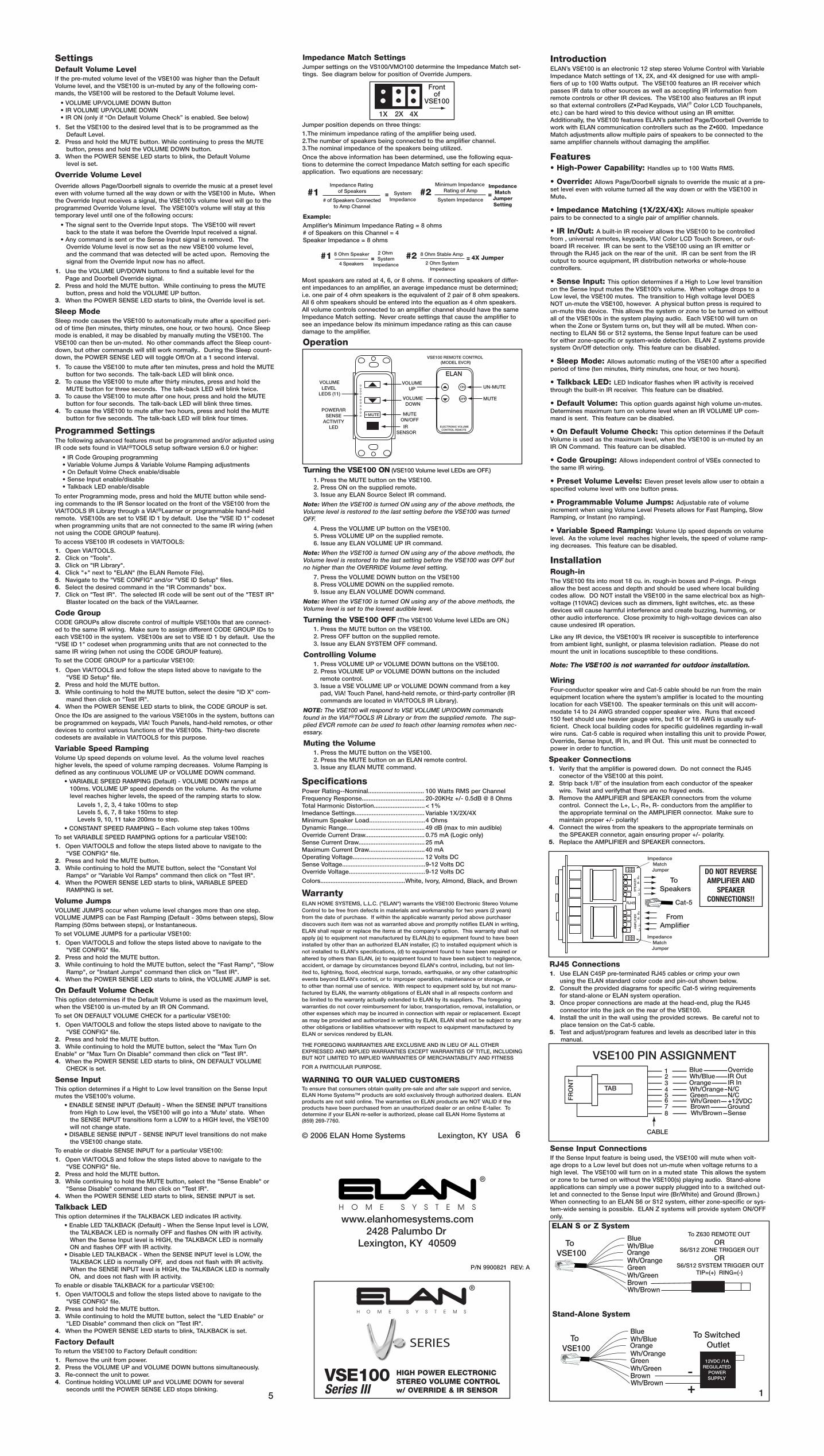
SettingsDefault Volume LevelIf the pre-muted volume level of the VSE100 was higher than the Default Volume level, and the VSE100 is un-muted by any of the following com-mands, the VSE100 will be restored to the Default Volume level.
• VOLUME UP/VOLUME DOWN Button • IR VOLUME UP/VOLUME DOWN • IR ON (only if “On Default Volume Check” is enabled. See below)
1. Set the VSE100 to the desired level that is to be programmed as the Default Level.2. Press and hold the MUTE button. While continuing to press the MUTE button, press and hold the VOLUME DOWN button.3. When the POWER SENSE LED starts to blink, the Default Volume level is set.
Override Volume LevelOverride allows Page/Doorbell signals to override the music at a preset level even with volume turned all the way down or with the VSE100 in Mute. When the Override Input receives a signal, the VSE100’s volume level will go to the programmed Override Volume level. The VSE100’s volume will stay at this temporary level until one of the following occurs:
• The signal sent to the Override Input stops. The VSE100 will revert back to the state it was before the Override Input received a signal. • Any command is sent or the Sense Input signal is removed. The Override Volume level is now set as the new VSE100 volume level, and the command that was detected will be acted upon. Removing the signal from the Override Input now has no affect.
1. Use the VOLUME UP/DOWN buttons to find a suitable level for the Page and Doorbell Override signal. 2. Press and hold the MUTE button. While continuing to press the MUTE button, press and hold the VOLUME UP button.3. When the POWER SENSE LED starts to blink, the Override level is set.
Sleep ModeSleep mode causes the VSE100 to automatically mute after a specified peri-od of time (ten minutes, thirty minutes, one hour, or two hours). Once Sleep mode is enabled, it may be disabled by manually muting the VSE100. The VSE100 can then be un-muted. No other commands affect the Sleep count-down, but other commands will still work normally.. During the Sleep count-down, the POWER SENSE LED will toggle Off/On at a 1 second interval.
1. To cause the VSE100 to mute after ten minutes, press and hold the MUTE button for two seconds. The talk-back LED will blink once.2. To cause the VSE100 to mute after thirty minutes, press and hold the MUTE button for three seconds. The talk-back LED will blink twice.3. To cause the VSE100 to mute after one hour, press and hold the MUTE button for four seconds. The talk-back LED will blink three times.4. To cause the VSE100 to mute after two hours, press and hold the MUTE button for five seconds. The talk-back LED will blink four times.
Programmed SettingsThe following advanced features must be programmed and/or adjusted using IR code sets found in VIA!®TOOLS setup software version 6.0 or higher:
• IR Code Grouping programming • Variable Volume Jumps & Variable Volume Ramping adjustments • On Default Volme Check enable/disable • Sense Input enable/disable • Talkback LED enable/disable
To enter Programming mode, press and hold the MUTE button while send-ing commands to the IR Sensor located on the front of the VSE100 from the VIA!TOOLS IR Library through a VIA!®Learner or programmable hand-held remote. VSE100s are set to VSE ID 1 by default. Use the "VSE ID 1" codeset when programming units that are not connected to the same IR wiring (when not using the CODE GROUP feature).To access VSE100 IR codesets in VIA!TOOLS:1. Open VIA!TOOLS.2. Click on "Tools".3. Click on "IR Library".4. Click "+" next to "ELAN" (the ELAN Remote File).5. Navigate to the "VSE CONFIG" and/or "VSE ID Setup" files.6. Select the desired command in the "IR Commands" box.7. Click on "Test IR". The selected IR code will be sent out of the "TEST IR" Blaster located on the back of the VIA!Learner.
Code GroupCODE GROUPs allow discrete control of multiple VSE100s that are connect-ed to the same IR wiring. Make sure to assign different CODE GROUP IDs to each VSE100 in the system. VSE100s are set to VSE ID 1 by default. Use the "VSE ID 1" codeset when programming units that are not connected to the same IR wiring (when not using the CODE GROUP feature).To set the CODE GROUP for a particular VSE100:
1. Open VIA!TOOLS and follow the steps listed above to navigate to the "VSE ID Setup" file.2. Press and hold the MUTE button.3. While continuing to hold the MUTE button, select the desire "ID X" com- mand then click on "Test IR".4. When the POWER SENSE LED starts to blink, the CODE GROUP is set.Once the IDs are assigned to the various VSE100s in the system, buttons can be programmed on keypads, VIA! Touch Panels, hand-held remotes, or other devices to control various functions of the VSE100s. Thirty-two discrete codesets are available in VIA!TOOLS for this purpose.
Variable Speed RampingVolume Up speed depends on volume level. As the volume level reaches higher levels, the speed of volume ramping decreases. Volume Ramping is defined as any continuous VOLUME UP or VOLUME DOWN command. • VARIABLE SPEED RAMPING (Default) - VOLUME DOWN ramps at 100ms. VOLUME UP speed depends on the volume. As the volume level reaches higher levels, the speed of the ramping starts to slow. Levels 1, 2, 3, 4 take 100ms to step Levels 5, 6, 7, 8 take 150ms to step Levels 9, 10, 11 take 200ms to step. • CONSTANT SPEED RAMPING – Each volume step takes 100msTo set VARIABLE SPEED RAMPING options for a particular VSE100:1. Open VIA!TOOLS and follow the steps listed above to navigate to the "VSE CONFIG" file.2. Press and hold the MUTE button.3. While continuing to hold the MUTE button, select the "Constant Vol Ramps" or "Variable Vol Ramps" command then click on "Test IR".4. When the POWER SENSE LED starts to blink, VARIABLE SPEED RAMPING is set.
Volume JumpsVOLUME JUMPS occur when volume level changes more than one step. VOLUME JUMPS can be Fast Ramping (Default - 30ms between steps), Slow Ramping (50ms between steps), or Instantaneous.To set VOLUME JUMPS for a particular VSE100:1. Open VIA!TOOLS and follow the steps listed above to navigate to the "VSE CONFIG" file.2. Press and hold the MUTE button.3. While continuing to hold the MUTE button, select the "Fast Ramp", "Slow Ramp", or "Instant Jumps" command then click on "Test IR".4. When the POWER SENSE LED starts to blink, the VOLUME JUMP is set.
On Default Volume CheckThis option determines if the Default Volume is used as the maximum level, when the VSE100 is un-muted by an IR ON Command.To set ON DEFAULT VOLUME CHECK for a particular VSE100:1. Open VIA!TOOLS and follow the steps listed above to navigate to the "VSE CONFIG" file.2. Press and hold the MUTE button.3. While continuing to hold the MUTE button, select the "Max Turn On Enable" or "Max Turn On Disable" command then click on "Test IR".4. When the POWER SENSE LED starts to blink, ON DEFAULT VOLUME CHECK is set.
Sense Input This option determines if a Hight to Low level transition on the Sense Input mutes the VSE100’s volume. • ENABLE SENSE INPUT (Default) - When the SENSE INPUT transitions from High to Low level, the VSE100 will go into a ‘Mute’ state. When the SENSE INPUT transitions form a LOW to a HIGH level, the VSE100 will not change state. • DISABLE SENSE INPUT - SENSE INPUT level transitions do not make the VSE100 change state.To enable or disable SENSE INPUT for a particular VSE100:1. Open VIA!TOOLS and follow the steps listed above to navigate to the "VSE CONFIG" file.2. Press and hold the MUTE button.3. While continuing to hold the MUTE button, select the "Sense Enable" or "Sense Disable" command then click on "Test IR".4. When the POWER SENSE LED starts to blink, SENSE INPUT is set.
Talkback LED This option determines if the TALKBACK LED indicates IR activity. • Enable LED TALKBACK (Default) - When the Sense Input level is LOW, the TALKBACK LED is normally OFF and flashes ON with IR activity. When the Sense Input level is HIGH, the TALKBACK LED is normally ON and flashes OFF with IR activity. • Disable LED TALKBACK - When the SENSE INPUT level is LOW, the TALKBACK LED is normally OFF, and does not flash with IR activity. When the SENSE INPUT level is HIGH, the TALKBACK LED is normally ON, and does not flash with IR activity.To enable or disable TALKBACK for a particular VSE100:1. Open VIA!TOOLS and follow the steps listed above to navigate to the "VSE CONFIG" file.2. Press and hold the MUTE button.3. While continuing to hold the MUTE button, select the "LED Enable" or "LED Disable" command then click on "Test IR".4. When the POWER SENSE LED starts to blink, TALKBACK is set.
Factory DefaultTo return the VSE100 to Factory Default condition:1. Remove the unit from power.2. Press the VOLUME UP and VOLUME DOWN buttons simultaneously.3. Re-connect the unit to power.4. Continue holding VOLUME UP and VOLUME DOWN for several seconds until the POWER SENSE LED stops blinking.
Speaker Connections1. Verify that the amplifier is powered down. Do not connect the RJ45 conector of the VSE100 at this point.2. Strip back 1/8” of the insulation from each conductor of the speaker wire. Twist and verifythat there are no frayed ends.3. Remove the AMPLIFIER and SPEAKER connectors from the volume control. Connect the L+, L-, R+, R- conductors from the amplifier to the appropriate terminal on the AMPLIFIER connector. Make sure to maintain proper +/- polarity!4. Connect the wires from the speakers to the appropriate terminals on the SPEAKER connetor, again ensuring proper +/- polarity.5. Replace the AMPLIFIER and SPEAKER connectors.
BlueWh/BlueOrangeWh/OrangeGreenWh/GreenBrownWh/Brown
To VSE100
To Z630 REMOTE OUTOR
S6/S12 ZONE TRIGGER OUTOR
S6/S12 SYSTEM TRIGGER OUTTIP=(+) RING=(-)
BlueWh/BlueOrangeWh/OrangeGreenWh/GreenBrownWh/Brown +
-
To Switched Outlet
To VSE100
12VDC /1AREGULATED
POWERSUPPLY
1
ELAN S or Z System
Stand-Alone System
6
MUTE
ON
OFF
ELECTRONIC VOLUME CONTROL REMOTE
ELANVOLUME
UP
VOLUMEDOWN
MUTEON/OFFIR
SENSOR
UN-MUTE
MUTE
POWER/IRSENSE
ACTIVITYLED
VOLUMELEVEL
LEDS (11)
VSE100 REMOTE CONTROL (MODEL EVCR)
RJ45 Connections1. Use ELAN C45P pre-terminated RJ45 cables or crimp your own using the ELAN standard color code and pin-out shown below.2. Consult the provided diagrams for specific Cat-5 wiring requirements for stand-alone or ELAN system operation.3. Once proper connections are made at the head-end, plug the RJ45 connector into the jack on the rear of the VSE100. 4. Install the unit in the wall using the provided screws. Be careful not to place tension on the Cat-5 cable.5. Test and adjust/program features and levels as described later in this manual.
SpecificationsPower Rating--Nominal................................. 100 Watts RMS per ChannelFrequency Response..................................... 20-20KHz +/- 0.5dB @ 8 OhmsTotal Harmonic Distortion.............................. < 1%Imedance Settings......................................... Variable 1X/2X/4XMinimum Speaker Load................................. 4 OhmsDynamic Range.............................................. 49 dB (max to min audible)Override Current Draw................................... 0.75 mA (Logic only)Sense Current Draw....................................... 25 mAMaximum Current Draw................................. 40 mAOperating Voltage.......................................... 12 Volts DCSense Voltage................................................. 9-12 Volts DCOverride Voltage............................................. 9-12 Volts DC
Colors..................................................White, Ivory, Almond, Black, and Brown
WarrantyELAN HOME SYSTEMS, L.L.C. ("ELAN") warrants the VSE100 Electronic Stereo Volume Control to be free from defects in materials and workmanship for two years (2 years) from the date of purchase. If within the applicable warranty period above purchaser discovers such item was not as warranted above and promptly notifies ELAN in writing, ELAN shall repair or replace the items at the company's option. This warranty shall not apply (a) to equipment not manufactured by ELAN,(b) to equipment found to have been installed by other than an authorized ELAN installer, (C) to installed equipment which is not installed to ELAN's specifications, (d) to equipment found to have been repaired or altered by others than ELAN, (e) to equipment found to have been subject to negligence, accident, or damage by circumstances beyond ELAN's control, including, but not lim-ited to, lightning, flood, electrical surge, tornado, earthquake, or any other catastrophic events beyond ELAN's control, or to improper operation, maintenance or storage, or to other than normal use of service. With respect to equipment sold by, but not manu-factured by ELAN, the warranty obligations of ELAN shall in all respects conform and be limited to the warranty actually extended to ELAN by its suppliers. The foregoing warranties do not cover reimbursement for labor, transportation, removal, installation, or other expenses which may be incurred in connection with repair or replacement. Except as may be provided and authorized in writing by ELAN, ELAN shall not be subject to any other obligations or liabilities whatsoever with respect to equipment manufactured by ELAN or services rendered by ELAN.
THE FOREGOING WARRANTIES ARE EXCLUSIVE AND IN LIEU OF ALL OTHER EXPRESSED AND IMPLIED WARRANTIES EXCEPT WARRANTIES OF TITLE, INCLUDING BUT NOT LIMITED TO IMPLIED WARRANTIES OF MERCHANTABILITY AND FITNESS
FOR A PARTICULAR PURPOSE.
WARNING TO OUR VALUED CUSTOMERSTo ensure that consumers obtain quality pre-sale and after sale support and service, ELAN Home Systems™ products are sold exclusively through authorized dealers. ELAN products are not sold online. The warranties on ELAN products are NOT VALID if the products have been purchased from an unauthorized dealer or an online E-tailer. To determine if your ELAN re-seller is authorized, please call ELAN Home Systems at (859) 269-7760.
© 2006 ELAN Home Systems Lexington, KY USA
Impedance Match SettingsJumper settings on the VS100/VMO100 determine the Impedance Match set-tings. See diagram below for position of Override Jumpers.
Impedance Rating of Speakers
# of Speakers Connectedto Amp Channel
SystemImpedance
ImpedanceMatch
JumperSetting
=#1 #2Minimum Impedance
Rating of Amp
System Impedance=
Operation
4 Speakers
8 Ohm Stable Amp4X Jumper
8 Ohm Speaker 2 Ohm System
Impedance=#1 #2
2 Ohm System Impedance
=
Most speakers are rated at 4, 6, or 8 ohms. If connecting speakers of differ-ent impedances to an amplifier, an average impedance must be determined; i.e. one pair of 4 ohm speakers is the equivalent of 2 pair of 8 ohm speakers. All 6 ohm speakers should be entered into the equation as 4 ohm speakers. All volume controls connected to an amplifier channel should have the same Impedance Match setting. Never create settings that cause the amplifier to see an impedance below its minimum impedance rating as this can cause damage to the amplifier.
Example:Amplifier’s Minimum Impedance Rating = 8 ohms# of Speakers on this Channel = 4Speaker Impedance = 8 ohms
Jumper position depends on three things:1.The minimum impedance rating of the amplifier being used.2.The number of speakers being connected to the amplifier channel.3.The nominal impedance of the speakers being utilized.Once the above information has been determined, use the following equa-tions to determine the correct Impedance Match setting for each specific application. Two equations are necessary:
1X 2X 4X
Frontof
VSE100
Z•PAD
VSE100
Punchdown Block
Blue (Override)
BlueWh/BlueOrangeWh/OrangeGreenWh/GreenBrownWh/Brown
BlueWh/BlueOrangeWh/OrangeGreenWh/GreenBrownWh/Brown
TIP Blue
SLEEVE Green
TIP SLEEVE
S6 ZONEKEYPADINPUT
S6 PAGETRIG IN
Z600 CONTROLOUTPUT
+
-
Blue (Override)
Blue (Override)
USE REGULATED 12VDCPOWER SUPPLY (12VDC/1 AMP)
12VDC 1 AMP
VSE100
VSE100
ZPAD
VSE100
Punchdown Block
Blue (Override)
BlueWh/BlueOrangeWh/OrangeGreenWh/GreenBrownWh/Brown
BlueWh/BlueOrangeWh/OrangeGreenWh/GreenBrownWh/Brown
TIP Blue
SLEEVE Green
TIP SLEEVE
S6 ZONEKEYPADINPUT
S6 PAGETRIG IN
Z600 CONTROLOUTPUT
MUTE
IROut
CAT-5
ZONE 1 (FIXED)
ZONE 1 (VARIABLE)
IR
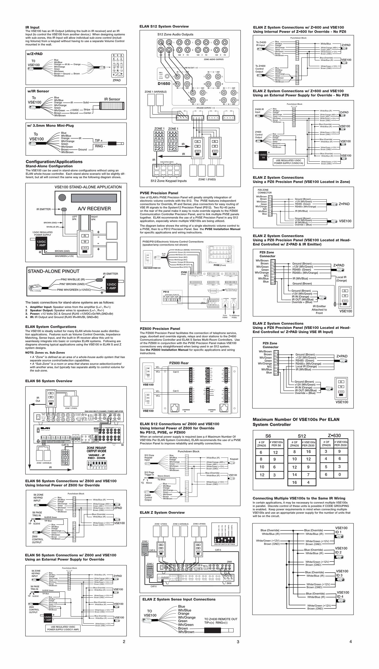
ELAN System ConfigurationsThe VSE100 is ideally suited for many ELAN whole-house audio distribu-tion applications. Features such as Volume Control Override, Impedance Matching, Sense Input, and the built-in IR receiver allow this unit to seamlessly integrate into basic or complex ELAN systems. Following are diagrams showing typical applications using the VSE100 in ELAN S and Z system designs.
NOTE: Zones vs. Sub-Zones
• A “Zone” is defined as an area of a whole-house audio system that has separate source control/selection capabilities. • A “Sub-Zone” is a room or area that shares source selection/control with another area, but typically has separate ability to control volume for the sub-zone.
ELAN S6 System Connections w/ Z600 and VSE100Using an External Power Supply for Override
ELAN S6 System Connections w/ Z600 and VSE100Using Internal Power of Z600 for Override
ELAN S6 System Overview
Configuration/ApplicationsStand-Alone ConfigurationThe VSE100 can be used in stand-alone configuations without using an ELAN whole-house controller. Each stand-alone scenario will be slightly dif-ferent, but all will connect the same way as the following diagram shows.
PIN2 WH/BLUE (IR)
PIN6 WH/GREEN (+12VDC)
PIN7 BROWN (GND)
+-
STAND-ALONE PINOUTIR EMITTER
12VDC 1 AMP
MUTE
12VDC REGULATED POWER SUPPLY
A/V RECEIVER
+ -WH/GREEN (+12V)
BROWN (GND)
LEFTSPK
RIGHT SPK
WH/BLUE (IR)
BROWN (GND)
+
-+
-
IR EMITTER
VSE100 STAND-ALONE APPLICATION
12VDC 1 AMP
2 3
BlueWh/BlueOrangeWh/OrangeGreenWh/GreenBrownWh/Brown
IR IN
Ground
ZPAD
T0 VSE100 Orange
Brown
w/Z•PAD
BlueWh/BlueOrangeWh/OrangeGreenWh/GreenBrownWh/Brown
IR
Ground
To VSE100
+12VDCCenterStripe
SolidIR Sensor
w/IR Sensor
BlueWh/BlueOrangeWh/OrangeGreenWh/GreenBrownWh/Brown
IR
Ground
To VSE100 TIP +
RING -
w/ 3.5mm Mono Mini-Plug
4
The basic connections for stand-alone systems are as follows:1. Amplifier Input: Speaker wires from the amplifier (L+/-, R+/-)2 Speaker Output: Speaker wires to speakers (L+/-, R+/-)3. Power: +12 Volts DC & Ground (RJ45 +12VDC=Gr/Wh,GND=Br)4. IR: IR Output and Ground (RJ45 IR=Wh/Bl, GND=Br)
ELAN Z System Overview
ELAN Z System Connections w/ Z•600 and VSE100Using Internal Power of Z•600 for Override - No PZ6
ELAN Z System Connections w/ Z•600 and VSE100Using an External Power Supply for Override - No PZ6
ELAN Z System ConnectionsUsing a PZ6 Precision Panel (VSE100 Located in Zone)
ELAN Z System ConnectionsUsing a PZ6 Precision Panel (VSE100 Located at Head-End Controlled w/ Z•PAD & IR Emitter)
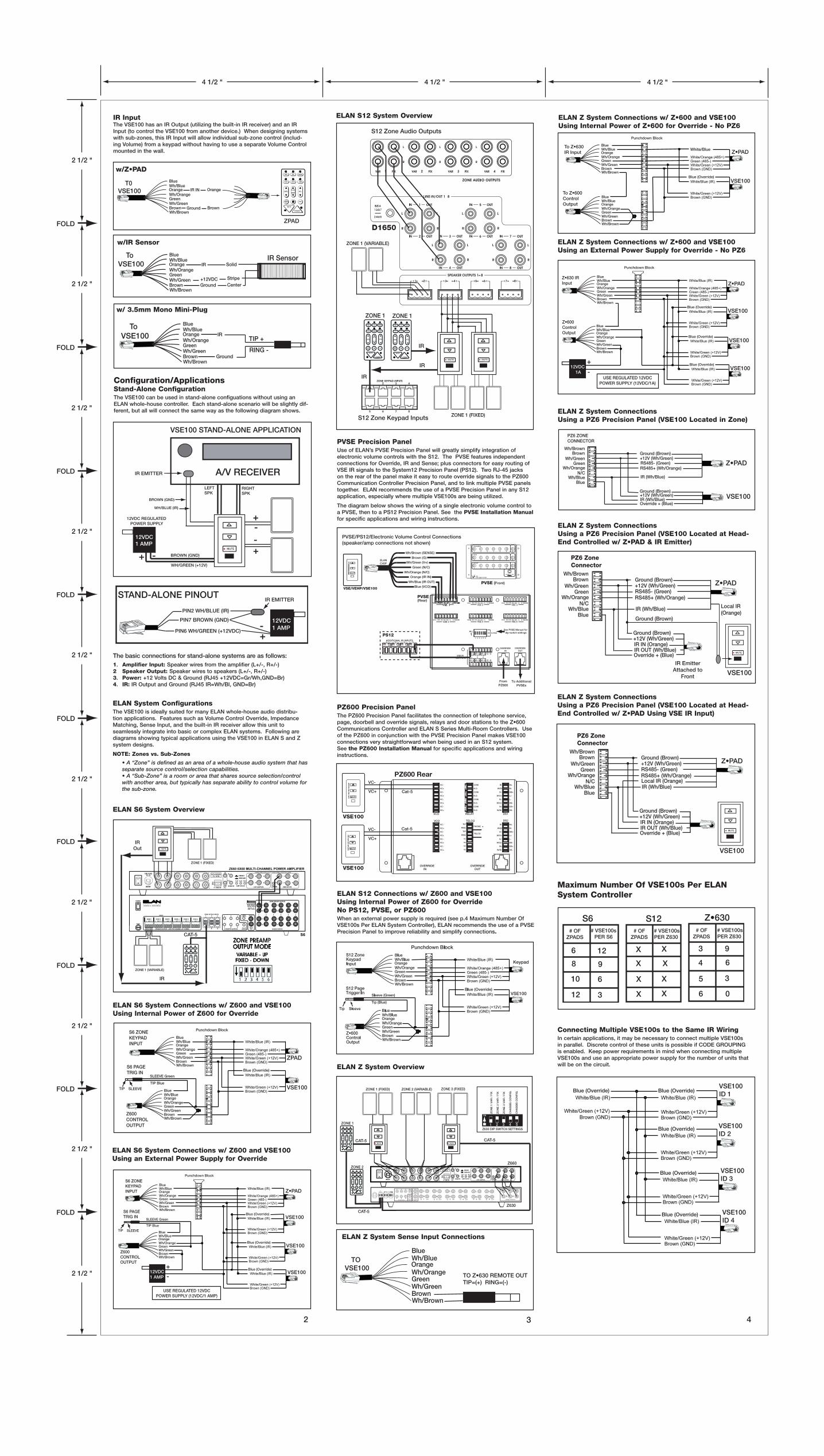
IR Input The VSE100 has an IR Output (utilizing the built-in IR receiver) and an IR Input (to control the VSE100 from another device.) When designing systems with sub-zones, this IR Input will allow individual sub-zone control (includ-ing Volume) from a keypad without having to use a separate Volume Control mounted in the wall.
MUTE
CAT-5MUTE
ZONE 1 (FIXED) ZONE 2 (VARIABLE) ZONE 3 (FIXED)
ZO
NE
1 V
AR
/ F
IX
ZO
NE
2 V
AR
/ F
IX
ZO
NE
3 V
AR
/ F
IX
CH
AS
SIS
CO
NF
IG.
CH
AS
SIS
CO
NF
IG.
ON
1 2 3 4 5Z630 DIP SWITCH SETTINGS
Z630
Z660
CAT-5
ZONE 1
ZONE 2
CAT-5
Z•PAD
VSE100
Punchdown Block
Blue (Override)
BlueWh/BlueOrangeWh/OrangeGreenWh/GreenBrownWh/Brown
White/Blue
BlueWh/BlueOrangeWh/OrangeGreenWh/GreenBrownWh/Brown
To Z•630IR Input
To Z•600ControlOutput
Z•PAD
VSE100
Punchdown Block
Blue (Override)
BlueWh/BlueOrangeWh/OrangeGreenWh/GreenBrownWh/Brown
BlueWh/BlueOrangeWh/OrangeGreenWh/GreenBrownWh/Brown
Z•630 IRInput
Z•600 ControlOutput
+
-
VSE100Blue (Override)
VSE100Blue (Override)
USE REGULATED 12VDCPOWER SUPPLY (12VDC/1A)
12VDC 1A
Z•PAD
VSE100
Wh/BrownBrown
Wh/GreenGreen
Wh/OrangeN/C
Wh/BlueBlue
Ground (Brown)+12V (Wh/Green)RS485- (Green)RS485+ (Wh/Orange)
IR (Wh/Blue)
Ground (Brown)+12V (Wh/Green)IR (Wh/Blue)Override + (Blue)
PZ6 ZONECONNECTOR
Z•PAD
VSE100
Wh/BrownBrown
Wh/GreenGreen
Wh/OrangeN/C
Wh/BlueBlue
Ground (Brown)+12V (Wh/Green)RS485- (Green)RS485+ (Wh/Orange)
Ground (Brown)+12V (Wh/Green)
IR OUT (Wh/Blue)Override + (Blue)
PZ6 ZoneConnector
IR IN (Orange)
IR (Wh/Blue)
IR EmitterAttached to
Front
MUTE
Local IR(Orange)
Ground (Brown)
ELAN S12 System Overview
D1650
S12 Zone Keypad Inputs
MUTE
ZONE 1 (VARIABLE)
S12 Zone Audio Outputs
ZONE 1 ZONE 1
MUTE
ZONE 1 (FIXED)
IR
IR
IR
ELAN S12 Connections w/ Z600 and VSE100Using Internal Power of Z600 for Override No PS12, PVSE, or PZ600When an external power supply is required (see p.4 Maximum Number Of VSE100s Per ELAN System Controller), ELAN recommends the use of a PVSE Precision Panel to improve reliability and simplify connections.
Tip (Blue)
VSE100
PVSE Precision PanelUse of ELAN’s PVSE Precision Panel will greatly simplify integration of electronic volume controls with the S12. The PVSE features independent connections for Override, IR and Sense; plus connectors for easy routing of VSE IR signals to the System12 Precision Panel (PS12). Two RJ-45 jacks on the rear of the panel make it easy to route override signals to the PZ600 Communication Controller Precision Panel, and to link multiple PVSE panels together. ELAN recommends the use of a PVSE Precision Panel in any S12 application, especially where multiple VSE100s are being utilized.
The diagram below shows the wiring of a single electronic volume control to a PVSE, then to a PS12 Precision Panel. See the PVSE Installation Manual for specific applications and wiring instructions.
SENSEGV+NC NCIROVCO IRISENSENC V+ GIROVCO IRI NCVSE 2 VSE 3
VSE 5 VSE 6VSE 4SENSEGV+NCNCIRIIROVCOSENSEIROVCO NCIRI NC V+ G GVCO NCIRIIRO V+NC SENSE
GG IR GIR
GIR GG G G
VSE IROUTPUTS
OVERRIDEOUT
OVERRIDEIN
1 2 34 5
GGIR
6IR
ALL
1 2 3 4 5 6
IR ROUTING
IR
PVSE(Rear)
Blue (VCO)
Wh/Blue (IR OUT)
Orange (IR IN)
Wh/Orange (N/C)
Green (N/C)
Wh/Green (V+)
Brown (G)
Wh/Brown (SENSE)
FromPZ600
To AdditionalPVSEs
See PVSE Manual for dip-switch settings
PVSE/PS12/Electronic Volume Control Connections(speaker/amp connections not shown)
ELANC45P
ADDITIONAL IR INPUTS
IRIR G1
IRG2
G3
IR G4
PS12
VSE/VEHP/VSE100
PVSE (Front)
PZ600 Precision PanelThe PZ600 Precision Panel facilitates the connection of telephone service, page, doorbell and override signals, relays and door stations to the Z•600 Communications Controller and ELAN S Series Multi-Room Controllers. Use of the PZ600 in conjunction with the PVSE Precision Panel makes VSE100 connections very straightforward when being used in an S12 system. See the PZ600 Installation Manual for specific applications and wiring instructions.
VSE100
VSE100
VC+
VC-
VC+
VC- Cat-5
Cat-5
OVERRIDEOUT
OVERRIDEIN
VCO
COM
N.O.
COM
N.O.
COM
N.O.
COM
N.O.
W/Bl
Br
W/Br
W/Or
W/Gr
Gr
Or
Bl
RELAY DS1
M-
DS+
DS-
L+
L-
DB-
DB+
M+
L+
DS-
DS+
L-
DB-
M-
DB+
M+
DS2
W/Or
W/Br
Br
W/Gr
Gr
W/Bl
Or
Bl
RNG
nc
nc
nc
nc
TIP
TIP
RNG
43
21
PHONE
TELCO
VC+
VC-
VC-
VC+
VC+
VC-
VC-
VC+
VC-
VC-
VC+
VC+
VC+
VC-
VC+
VC-
PZ600 Rear
VCO TELCO
BlueWh/BlueOrangeWh/OrangeGreenWh/GreenBrownWh/Brown
TO VSE100
TO Z•630 REMOTE OUTTIP=(+) RING=(-)
ELAN Z System Sense Input Connections
Maximum Number Of VSE100s Per ELAN System Controller
S6 Z•630S12 # OF ZPADS
# OF ZPADS
# OF ZPADS
# VSE100sPER S6
# VSE100sPER Z630
6
8
10
12
12
9
6
3
3
4
5
6
9
6
3
0
8
10
12
14
16
12
9
7
# VSE100sPER Z630
16 4
Connecting Multiple VSE100s to the Same IR WiringIn certain applications, it may be necessary to connect multiple VSE100s in parallel. Discrete control of these units is possible if CODE GROUPING is enabled. Keep power requirements in mind when connecting multiple VSE100s and use an appropriate power supply for the number of units that will be on the circuit.
VSE100 ID 1
VSE100 ID 2
Blue (Override)
VSE100 ID 3
Blue (Override)
VSE100 ID 4
Blue (Override)
Blue (Override)Blue (Override)
ELAN Z System ConnectionsUsing a PZ6 Precision Panel (VSE100 Located at Head-End Controlled w/ Z•PAD Using VSE IR Input)
Z•PAD
VSE100
Wh/BrownBrown
Wh/GreenGreen
Wh/OrangeN/C
Wh/BlueBlue
Ground (Brown)+12V (Wh/Green)RS485- (Green)RS485+ (Wh/Orange)
Ground (Brown)+12V (Wh/Green)
IR OUT (Wh/Blue)Override + (Blue)
PZ6 ZoneConnector
IR IN (Orange)
IR (Wh/Blue)
MUTE
Local IR (Orange)
www.elanhomesystems.com 2428 Palumbo Dr Lexington, KY 40509
®
VSE100 HIGH POWER ELECTRONIC STEREO VOLUME CONTROL w/ OVERRIDE & IR SENSOR
SERIES
®
Series III
www.elanhomesystems.com 2428 Palumbo Dr
Lexington, KY 40509
®
2 1/2"
4 1/2"
25"
FOLD 1FOLD 2
FOLD 3
FOLD 4
FOLD 5
FOLD 6
FOLD 7
FOLD 9
FOLD 106
FOLD 8
VSE100 HIGH POWER ELECTRONIC STEREO VOLUME CONTROL w/ OVERRIDE & IR SENSOR
SERIES
®
Series III
5
1
FOLD 11
www.elanhomesystems.com 2428 Palumbo Dr
Lexington, KY 40509
®
VSE100 HIGH POWER ELECTRONIC STEREO VOLUME CONTROL w/ OVERRIDE & IR SENSOR
SERIES
®
Series III
FOLD 11
FrontCover
BackCover
6
#1 #2
#3
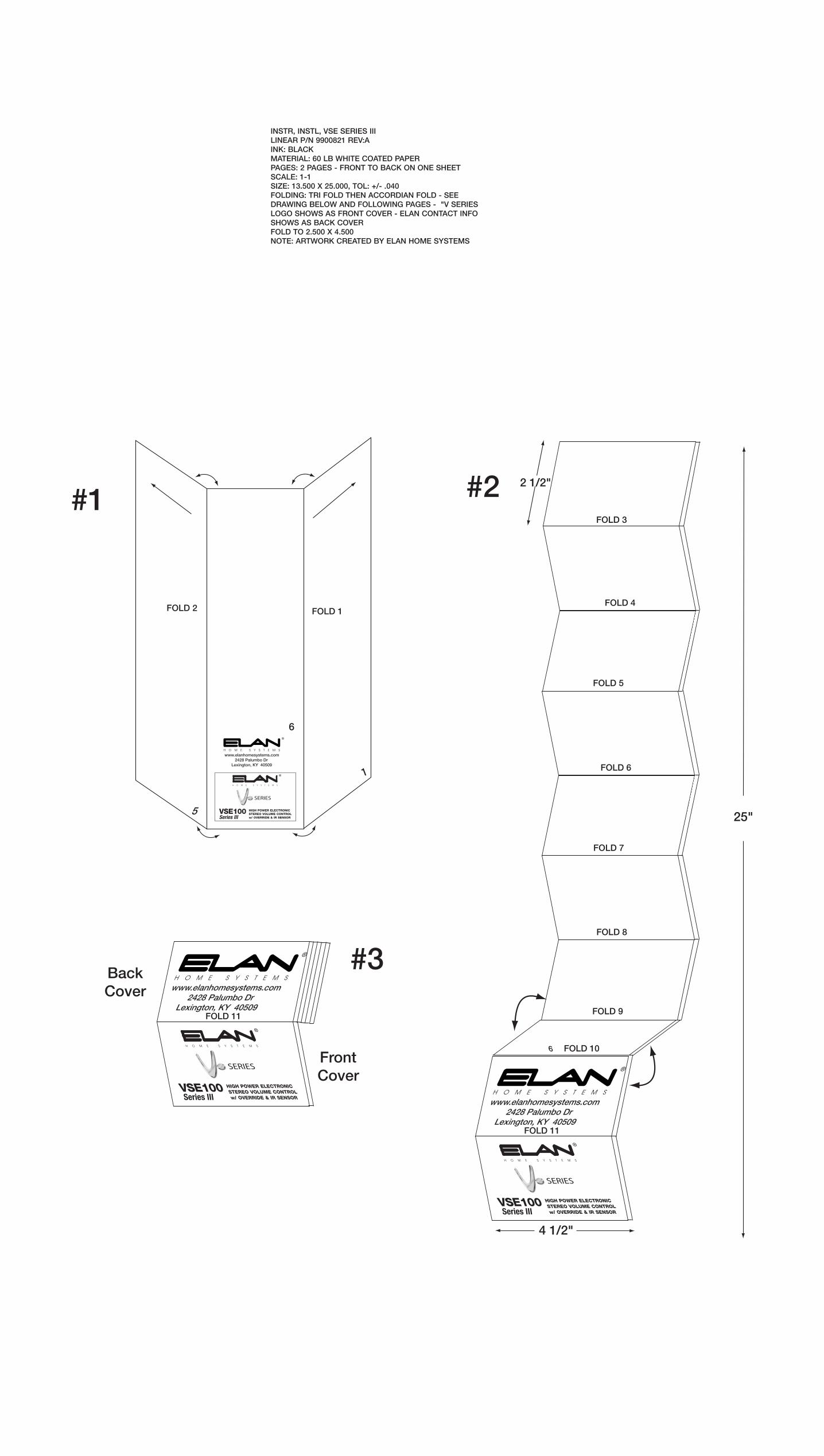
INSTR, INSTL, VSE SERIES IIILINEAR P/N 9900821 REV:AINK: BLACKMATERIAL: 60 LB WHITE COATED PAPERPAGES: 2 PAGES - FRONT TO BACK ON ONE SHEET SCALE: 1-1SIZE: 13.500 X 25.000, TOL: +/- .040FOLDING: TRI FOLD THEN ACCORDIAN FOLD - SEE DRAWING BELOW AND FOLLOWING PAGES - "V SERIES LOGO SHOWS AS FRONT COVER - ELAN CONTACT INFO SHOWS AS BACK COVERFOLD TO 2.500 X 4.500NOTE: ARTWORK CREATED BY ELAN HOME SYSTEMS

FOLD
FOLD
FOLD
FOLD
FOLD
FOLD
FOLD
FOLD
FOLD
2 1/2 "
2 1/2 "
2 1/2 "
2 1/2 "
2 1/2 "
2 1/2 "
2 1/2 "
2 1/2 "
2 1/2 "
2 1/2 "
4 1/2 " 4 1/2 " 4 1/2 "
IntroductionELAN’s VSE100 is an electronic 12 step stereo Volume Control with Variable Impedance Match settings of 1X, 2X, and 4X designed for use with ampli-fiers of up to 100 Watts output. The VSE100 features an IR receiver which passes IR data to other sources as well as accepting IR information from remote controls or other IR devices. The VSE100 also features an IR input so that external controllers (Z•Pad Keypads, VIA!® Color LCD Touchpanels, etc.) can be hard wired to this device without using an IR emitter. Additionally, the VSE100 features ELAN’s patented Page/Doorbell Override to work with ELAN communication controllers such as the Z•600. Impedance Match adjustments allow multiple pairs of speakers to be connected to the same amplifier channels without damaging the amplifier.
Features• High-Power Capability: Handles up to 100 Watts RMS.
• Override: Allows Page/Doorbell signals to override the music at a pre-set level even with volume turned all the way down or with the VSE100 in Mute.
• Impedance Matching (1X/2X/4X): Allows multiple speaker pairs to be connected to a single pair of amplifier channels.
• IR In/Out: A built-in IR receiver allows the VSE100 to be controlled from , universal remotes, keypads, VIA! Color LCD Touch Screen, or out-board IR receiver. IR can be sent to the VSE100 using an IR emitter or through the RJ45 jack on the rear of the unit. IR can be sent from the IR output to source equipment, IR distribution networks or whole-house controllers.
• Sense Input: This option determines if a High to Low level transition on the Sense Input mutes the VSE100’s volume. When voltage drops to a Low level, the VSE100 mutes. The transition to High voltage level DOES NOT un-mute the VSE100, however. A physical button press is required to un-mute this device. This allows the system or zone to be turned on without all of the VSE100s in the system playing audio. Each VSE100 will turn on when the Zone or System turns on, but they will all be muted. When con-necting to ELAN S6 or S12 systems, the Sense Input feature can be used for either zone-specific or system-wide detection. ELAN Z systems provide system On/Off detection only. This feature can be disabled.
• Sleep Mode: Allows automatic muting of the VSE100 after a specified period of time (ten minutes, thirty minutes, one hour, or two hours).
• Talkback LED: LED Indicator flashes when IR activity is received through the built-in IR receiver. This feature can be disabled.
• Default Volume: This option guards against high volume un-mutes. Determines maximum turn on volume level when an IR VOLUME UP com-mand is sent. This feature can be disabled.
• On Default Volume Check: This option determines if the Default Volume is used as the maximum level, when the VSE100 is un-muted by an IR ON Command. This feature can be disabled.
• Code Grouping: Allows independent control of VSEs connected to the same IR wiring.
• Preset Volume Levels: Eleven preset levels allow user to obtain a specified volume level with one button press.
• Programmable Volume Jumps: Adjustable rate of volume increment when using Volume Level Presets allows for Fast Ramping, Slow Ramping, or Instant (no ramping).
• Variable Speed Ramping: Volume Up speed depends on volume level. As the volume level reaches higher levels, the speed of volume ramp-ing decreases. This feature can be disabled.
InstallationRough-inThe VSE100 fits into most 18 cu. in. rough-in boxes and P-rings. P-rings allow the best access and depth and should be used where local building codes allow. DO NOT install the VSE100 in the same electrical box as high-voltage (110VAC) devices such as dimmers, light switches, etc. as these devices will cause harmful interference and create buzzing, humming, or other audio interference. Close proximity to high-voltage devices can also cause undesired IR operation.
Like any IR device, the VSE100’s IR receiver is susceptible to interference from ambient light, sunlight, or plasma television radiation. Please do not mount the unit in locations susceptible to these conditions.
Note: The VSE100 is not warranted for outdoor installation.
WiringFour-conductor speaker wire and Cat-5 cable should be run from the main equipment location where the system’s amplifier is located to the mounting location for each VSE100. The speaker terminals on this unit will accom-modate 14 to 24 AWG stranded copper speaker wire. Runs that exceed 150 feet should use heavier gauge wire, but 16 or 18 AWG is usually suf-ficient. Check local building codes for specific guidelines regarding in-wall wire runs. Cat-5 cable is required when installing this unit to provide Power, Override, Sense Input, IR In, and IR Out. This unit must be connected to power in order to function.
BlueWh/BlueOrangeWh/OrangeGreenWh/GreenBrownWh/Brown
12345678
TAB
TN
OR
F
CABLE
OverrideIR OutIR InN/CN/C+12VDCGroundSense
VSE100 PIN ASSIGNMENT
RJ45
REI
FILP
MA
RE
KA
EP
SL
+L-
R -R
+L
+L-
R -R
+
To Speakers
FromAmplifier
Cat-5
Impedance Match Jumper
Impedance Match Jumper
5
Turning the VSE100 ON (VSE100 Volume level LEDs are OFF.)
1. Press the MUTE button on the VSE100. 2. Press ON on the supplied remote. 3. Issue any ELAN Source Select IR command. Note: When the VSE100 is turned ON using any of the above methods, the Volume level is restored to the last setting before the VSE100 was turned OFF.
4. Press the VOLUME UP button on the VSE100. 5. Press VOLUME UP on the supplied remote. 6. Issue any ELAN VOLUME UP IR command.
Note: When the VSE100 is turned ON using any of the above methods, theVolume level is restored to the last setting before the VSE100 was OFF but no higher than the OVERRIDE Volume level setting.
7. Press the VOLUME DOWN button on the VSE100 8. Press VOLUME DOWN on the supplied remote. 9. Issue any ELAN VOLUME DOWN command.
Note: When the VSE100 is turned ON using any of the above methods, theVolume level is set to the lowest audible level.
Turning the VSE100 OFF (The VSE100 Volume level LEDs are ON.) 1. Press the MUTE button on the VSE100. 2. Press OFF button on the supplied remote. 3. Issue any ELAN SYSTEM OFF command.
Controlling Volume 1. Press VOLUME UP or VOLUME DOWN buttons on the VSE100. 2. Press VOLUME UP or VOLUME DOWN buttons on the included remote control. 3. Issue a VSE VOLUME UP or VOLUME DOWN command from a key pad, VIA! Touch Panel, hand-held remote, or third-party controller (IR commands are located in VIA!TOOLS IR Library).
NOTE: The VSE100 will respond to VSE VOLUME UP/DOWN commands found in the VIA!®TOOLS IR Library or from the supplied remote. The sup-plied EVCR remote can be used to teach other learning remotes when nec-essary.
Muting the Volume 1. Press the MUTE button on the VSE100. 2. Press the MUTE button on an ELAN remote control. 3. Issue any ELAN MUTE command.
VSE100 HIGH POWER ELECTRONIC STEREO VOLUME CONTROL w/ OVERRIDE & IR SENSOR
®
www.elanhomesystems.com 2428 Palumbo Dr Lexington, KY 40509
®
P/N 9900821 REV: A
Sense Input ConnectionsIf the Sense Input feature is being used, the VSE100 will mute when volt-age drops to a Low level but does not un-mute when voltage returns to a high level. The VSE100 will turn on in a muted state This allows the system or zone to be turned on without the VSE100(s) playing audio. Stand-alone applications can simply use a power supply plugged into to a switched out-let and connected to the Sense Input wire (Br/White) and Ground (Brown.) When connecting to an ELAN S6 or S12 system, either zone-specific or sys-tem-wide sensing is possible. ELAN Z systems will provide system ON/OFF only.
SettingsDefault Volume LevelIf the pre-muted volume level of the VSE100 was higher than the Default Volume level, and the VSE100 is un-muted by any of the following com-mands, the VSE100 will be restored to the Default Volume level.
• VOLUME UP/VOLUME DOWN Button • IR VOLUME UP/VOLUME DOWN • IR ON (only if “On Default Volume Check” is enabled. See below)
1. Set the VSE100 to the desired level that is to be programmed as the Default Level.2. Press and hold the MUTE button. While continuing to press the MUTE button, press and hold the VOLUME DOWN button.3. When the POWER SENSE LED starts to blink, the Default Volume level is set.
Override Volume LevelOverride allows Page/Doorbell signals to override the music at a preset level even with volume turned all the way down or with the VSE100 in Mute. When the Override Input receives a signal, the VSE100’s volume level will go to the programmed Override Volume level. The VSE100’s volume will stay at this temporary level until one of the following occurs:
• The signal sent to the Override Input stops. The VSE100 will revert back to the state it was before the Override Input received a signal. • Any command is sent or the Sense Input signal is removed. The Override Volume level is now set as the new VSE100 volume level, and the command that was detected will be acted upon. Removing the signal from the Override Input now has no affect.
1. Use the VOLUME UP/DOWN buttons to find a suitable level for the Page and Doorbell Override signal. 2. Press and hold the MUTE button. While continuing to press the MUTE button, press and hold the VOLUME UP button.3. When the POWER SENSE LED starts to blink, the Override level is set.
Sleep ModeSleep mode causes the VSE100 to automatically mute after a specified peri-od of time (ten minutes, thirty minutes, one hour, or two hours). Once Sleep mode is enabled, it may be disabled by manually muting the VSE100. The VSE100 can then be un-muted. No other commands affect the Sleep count-down, but other commands will still work normally.. During the Sleep count-down, the POWER SENSE LED will toggle Off/On at a 1 second interval.
1. To cause the VSE100 to mute after ten minutes, press and hold the MUTE button for two seconds. The talk-back LED will blink once.2. To cause the VSE100 to mute after thirty minutes, press and hold the MUTE button for three seconds. The talk-back LED will blink twice.3. To cause the VSE100 to mute after one hour, press and hold the MUTE button for four seconds. The talk-back LED will blink three times.4. To cause the VSE100 to mute after two hours, press and hold the MUTE button for five seconds. The talk-back LED will blink four times.
Programmed SettingsThe following advanced features must be programmed and/or adjusted using IR code sets found in VIA!®TOOLS setup software version X.X or higher:
• IR Code Grouping programming • Variable Volume Jumps & Variable Volume Ramping adjustments • On Default Volme Check enable/disable • Sense Input enable/disable • Talkback LED enable/disable
To enter Programming mode, press and hold the MUTE button while send-ing commands to the IR Sensor located on the front of the VSE100 from the VIA!TOOLS IR Library through a VIA!®Learner or programmable hand-held remote. VSE100s are set to VSE ID 1 by default. Use the "VSE ID 1" codeset when programming units that are not connected to the same IR wiring (when not using the CODE GROUP feature).To access VSE100 IR codesets in VIA!TOOLS:1. Open VIA!TOOLS.2. Click on "Tools".3. Click on "IR Library".4. Click "+" next to "ELAN" (the ELAN Remote File).5. Navigate to the "VSE CONFIG" and/or "VSE ID Setup" files.6. Select the desired command in the "IR Commands" box.7. Click on "Test IR". The selected IR code will be sent out of the "TEST IR" Blaster located on the back of the VIA!Learner.
Code GroupCODE GROUPs allow discrete control of multiple VSE100s that are connect-ed to the same IR wiring. Make sure to assign different CODE GROUP IDs to each VSE100 in the system. VSE100s are set to VSE ID 1 by default. Use the "VSE ID 1" codeset when programming units that are not connected to the same IR wiring (when not using the CODE GROUP feature).To set the CODE GROUP for a particular VSE100:
1. Open VIA!TOOLS and follow the steps listed above to navigate to the "VSE ID Setup" file.2. Press and hold the MUTE button.3. While continuing to hold the MUTE button, select the desire "ID X" com- mand then click on "Test IR".4. When the POWER SENSE LED starts to blink, the CODE GROUP is set.Once the IDs are assigned to the various VSE100s in the system, buttons can be programmed on keypads, VIA! Touch Panels, hand-held remotes, or other devices to control various functions of the VSE100s. Thirty-two discrete codesets are available in VIA!TOOLS for this purpose.
Variable Speed RampingVolume Up speed depends on volume level. As the volume level reaches higher levels, the speed of volume ramping decreases. Volume Ramping is defined as any continuous VOLUME UP or VOLUME DOWN command. • VARIABLE SPEED RAMPING (Default) - VOLUME DOWN ramps at 100ms. VOLUME UP speed depends on the volume. As the volume level reaches higher levels, the speed of the ramping starts to slow. Levels 1, 2, 3, 4 take 100ms to step Levels 5, 6, 7, 8 take 150ms to step Levels 9, 10, 11 take 200ms to step. • CONSTANT SPEED RAMPING – Each volume step takes 100msTo set VARIABLE SPEED RAMPING options for a particular VSE100:1. Open VIA!TOOLS and follow the steps listed above to navigate to the "VSE CONFIG" file.2. Press and hold the MUTE button.3. While continuing to hold the MUTE button, select the "Constant Vol Ramps" or "Variable Vol Ramps" command then click on "Test IR".4. When the POWER SENSE LED starts to blink, VARIABLE SPEED RAMPING is set.
Volume JumpsVOLUME JUMPS occur when volume level changes more than one step. VOLUME JUMPS can be Fast Ramping (Default - 30ms between steps), Slow Ramping (50ms between steps), or Instantaneous.To set VOLUME JUMPS for a particular VSE100:1. Open VIA!TOOLS and follow the steps listed above to navigate to the "VSE CONFIG" file.2. Press and hold the MUTE button.3. While continuing to hold the MUTE button, select the "Fast Ramp", "Slow Ramp", or "Instant Jumps" command then click on "Test IR".4. When the POWER SENSE LED starts to blink, the VOLUME JUMP is set.
On Default Volume CheckThis option determines if the Default Volume is used as the maximum level, when the VSE100 is un-muted by an IR ON Command.To set ON DEFAULT VOLUME CHECK for a particular VSE100:1. Open VIA!TOOLS and follow the steps listed above to navigate to the "VSE CONFIG" file.2. Press and hold the MUTE button.3. While continuing to hold the MUTE button, select the "Max Turn On Enable" or "Max Turn On Disable" command then click on "Test IR".4. When the POWER SENSE LED starts to blink, ON DEFAULT VOLUME CHECK is set.
Sense Input This option determines if a Hight to Low level transition on the Sense Input mutes the VSE100’s volume. • ENABLE SENSE INPUT (Default) - When the SENSE INPUT transitions from High to Low level, the VSE100 will go into a ‘Mute’ state. When the SENSE INPUT transitions form a LOW to a HIGH level, the VSE100 will not change state. • DISABLE SENSE INPUT - SENSE INPUT level transitions do not make the VSE100 change state.To enable or disable SENSE INPUT for a particular VSE100:1. Open VIA!TOOLS and follow the steps listed above to navigate to the "VSE CONFIG" file.2. Press and hold the MUTE button.3. While continuing to hold the MUTE button, select the "Sense Enable" or "Sense Disable" command then click on "Test IR".4. When the POWER SENSE LED starts to blink, SENSE INPUT is set.
Talkback LED This option determines if the TALKBACK LED indicates IR activity. • Enable LED TALKBACK (Default) - When the Sense Input level is LOW, the TALKBACK LED is normally OFF and flashes ON with IR activity. When the Sense Input level is HIGH, the TALKBACK LED is normally ON and flashes OFF with IR activity. • Disable LED TALKBACK - When the SENSE INPUT level is LOW, the TALKBACK LED is normally OFF, and does not flash with IR activity. When the SENSE INPUT level is HIGH, the TALKBACK LED is normally ON, and does not flash with IR activity.To enable or disable TALKBACK for a particular VSE100:1. Open VIA!TOOLS and follow the steps listed above to navigate to the "VSE CONFIG" file.2. Press and hold the MUTE button.3. While continuing to hold the MUTE button, select the "LED Enable" or "LED Disable" command then click on "Test IR".4. When the POWER SENSE LED starts to blink, TALKBACK is set.
Factory DefaultTo return the VSE100 to Factory Default condition:1. Remove the unit from power.2. Press the VOLUME UP and VOLUME DOWN buttons simultaneously.3. Re-connect the unit to power.4. Continue holding VOLUME UP and VOLUME DOWN for several seconds until the POWER SENSE LED stops blinking.
Speaker Connections1. Verify that the amplifier is powered down. Do not connect the RJ45 conector of the VSE100 at this point.2. Strip back 1/8” of the insulation from each conductor of the speaker wire. Twist and verifythat there are no frayed ends.3. Remove the AMPLIFIER and SPEAKER connectors from the volume control. Connect the L+, L-, R+, R- conductors from the amplifier to the appropriate terminal on the AMPLIFIER connector. Make sure to maintain proper +/- polarity!4. Connect the wires from the speakers to the appropriate terminals on the SPEAKER connetor, again ensuring proper +/- polarity.5. Replace the AMPLIFIER and SPEAKER connectors.
BlueWh/BlueOrangeWh/OrangeGreenWh/GreenBrownWh/Brown
To VSE100
To Z630 REMOTE OUTOR
S6/S12 ZONE TRIGGER OUTOR
S6/S12 SYSTEM TRIGGER OUTTIP=(+) RING=(-)
BlueWh/BlueOrangeWh/OrangeGreenWh/GreenBrownWh/Brown +
-
To Switched Outlet
To VSE100
12VDC /1AREGULATED
POWERSUPPLY
1
ELAN S or Z System
Stand-Alone System
6
MUTE
ON
OFF
ELECTRONIC VOLUME CONTROL REMOTE
ELANVOLUME
UP
VOLUMEDOWN
MUTEON/OFFIR
SENSOR
UN-MUTE
MUTE
POWER/IRSENSE
ACTIVITYLED
VOLUMELEVEL
LEDS (11)
VSE100 REMOTE CONTROL (MODEL EVCR)
RJ45 Connections1. Use ELAN C45P pre-terminated RJ45 cables or crimp your own using the ELAN standard color code and pin-out shown below.2. Consult the provided diagrams for specific Cat-5 wiring requirements for stand-alone or ELAN system operation.3. Once proper connections are made at the head-end, plug the RJ45 connector into the jack on the rear of the VSE100. 4. Install the unit in the wall using the provided screws. Be careful not to place tension on the Cat-5 cable.5. Test and adjust/program features and levels as described later in this manual.
SpecificationsPower Rating--Nominal................................. 100 Watts RMS per ChannelFrequency Response..................................... 20-20KHz +/- 0.5dB @ 8 OhmsTotal Harmonic Distortion.............................. < 1%Imedance Settings......................................... Variable 1X/2X/4XMinimum Speaker Load................................. 4 OhmsDynamic Range.............................................. 49 dB (max to min audible)Override Current Draw................................... 0.75 mA (Logic only)Sense Current Draw....................................... 25 mAMaximum Current Draw................................. 40 mAOperating Voltage.......................................... 12 Volts DCSense Voltage................................................. 9-12 Volts DCOverride Voltage............................................. 9-12 Volts DC
Colors..................................................White, Ivory, Almond, Black, and Brown
WarrantyELAN HOME SYSTEMS, L.L.C. ("ELAN") warrants the VSE100 Electronic Stereo Volume Control to be free from defects in materials and workmanship for two years (2 years) from the date of purchase. If within the applicable warranty period above purchaser discovers such item was not as warranted above and promptly notifies ELAN in writing, ELAN shall repair or replace the items at the company's option. This warranty shall not apply (a) to equipment not manufactured by ELAN,(b) to equipment found to have been installed by other than an authorized ELAN installer, (C) to installed equipment which is not installed to ELAN's specifications, (d) to equipment found to have been repaired or altered by others than ELAN, (e) to equipment found to have been subject to negligence, accident, or damage by circumstances beyond ELAN's control, including, but not lim-ited to, lightning, flood, electrical surge, tornado, earthquake, or any other catastrophic events beyond ELAN's control, or to improper operation, maintenance or storage, or to other than normal use of service. With respect to equipment sold by, but not manu-factured by ELAN, the warranty obligations of ELAN shall in all respects conform and be limited to the warranty actually extended to ELAN by its suppliers. The foregoing warranties do not cover reimbursement for labor, transportation, removal, installation, or other expenses which may be incurred in connection with repair or replacement. Except as may be provided and authorized in writing by ELAN, ELAN shall not be subject to any other obligations or liabilities whatsoever with respect to equipment manufactured by ELAN or services rendered by ELAN.
THE FOREGOING WARRANTIES ARE EXCLUSIVE AND IN LIEU OF ALL OTHER EXPRESSED AND IMPLIED WARRANTIES EXCEPT WARRANTIES OF TITLE, INCLUDING BUT NOT LIMITED TO IMPLIED WARRANTIES OF MERCHANTABILITY AND FITNESS
FOR A PARTICULAR PURPOSE.
WARNING TO OUR VALUED CUSTOMERSTo ensure that consumers obtain quality pre-sale and after sale support and service, ELAN Home Systems™ products are sold exclusively through authorized dealers. ELAN products are not sold online. The warranties on ELAN products are NOT VALID if the products have been purchased from an unauthorized dealer or an online E-tailer. To determine if your ELAN re-seller is authorized, please call ELAN Home Systems at (859) 269-7760.
© 2006 ELAN Home Systems Lexington, KY USA
Impedance Match SettingsJumper settings on the VS100/VMO100 determine the Impedance Match set-tings. See diagram below for position of Override Jumpers.
Impedance Rating of Speakers
# of Speakers Connectedto Amp Channel
SystemImpedance
ImpedanceMatch
JumperSetting
=#1 #2Minimum Impedance
Rating of Amp
System Impedance=
Operation
4 Speakers
8 Ohm Stable Amp4X Jumper
8 Ohm Speaker 2 Ohm System
Impedance=#1 #2
2 Ohm System Impedance
=
Most speakers are rated at 4, 6, or 8 ohms. If connecting speakers of differ-ent impedances to an amplifier, an average impedance must be determined; i.e. one pair of 4 ohm speakers is the equivalent of 2 pair of 8 ohm speakers. All 6 ohm speakers should be entered into the equation as 4 ohm speakers. All volume controls connected to an amplifier channel should have the same Impedance Match setting. Never create settings that cause the amplifier to see an impedance below its minimum impedance rating as this can cause damage to the amplifier.
Example:Amplifier’s Minimum Impedance Rating = 8 ohms# of Speakers on this Channel = 4Speaker Impedance = 8 ohms
Jumper position depends on three things:1.The minimum impedance rating of the amplifier being used.2.The number of speakers being connected to the amplifier channel.3.The nominal impedance of the speakers being utilized.Once the above information has been determined, use the following equa-tions to determine the correct Impedance Match setting for each specific application. Two equations are necessary:
1X 2X 4X
Frontof
VSE100
FOLD
FOLD
FOLD
FOLD
FOLD
FOLD
FOLD
FOLD
FOLD
2 1/2 "
2 1/2 "
2 1/2 "
2 1/2 "
2 1/2 "
2 1/2 "
2 1/2 "
2 1/2 "
2 1/2 "
2 1/2 "
4 1/2 " 4 1/2 " 4 1/2 "
Z•PAD
VSE100
Punchdown Block
Blue (Override)
BlueWh/BlueOrangeWh/OrangeGreenWh/GreenBrownWh/Brown
BlueWh/BlueOrangeWh/OrangeGreenWh/GreenBrownWh/Brown
TIP Blue
SLEEVE Green
TIP SLEEVE
S6 ZONEKEYPADINPUT
S6 PAGETRIG IN
Z600 CONTROLOUTPUT
+
-
Blue (Override)
Blue (Override)
USE REGULATED 12VDCPOWER SUPPLY (12VDC/1 AMP)
12VDC 1 AMP
VSE100
VSE100
ZPAD
VSE100
Punchdown Block
Blue (Override)
BlueWh/BlueOrangeWh/OrangeGreenWh/GreenBrownWh/Brown
BlueWh/BlueOrangeWh/OrangeGreenWh/GreenBrownWh/Brown
TIP Blue
SLEEVE Green
TIP SLEEVE
S6 ZONEKEYPADINPUT
S6 PAGETRIG IN
Z600 CONTROLOUTPUT
MUTE
IROut
CAT-5
ZONE 1 (FIXED)
ZONE 1 (VARIABLE)
IR
ELAN System ConfigurationsThe VSE100 is ideally suited for many ELAN whole-house audio distribu-tion applications. Features such as Volume Control Override, Impedance Matching, Sense Input, and the built-in IR receiver allow this unit to seamlessly integrate into basic or complex ELAN systems. Following are diagrams showing typical applications using the VSE100 in ELAN S and Z system designs.
NOTE: Zones vs. Sub-Zones
• A “Zone” is defined as an area of a whole-house audio system that has separate source control/selection capabilities. • A “Sub-Zone” is a room or area that shares source selection/control with another area, but typically has separate ability to control volume for the sub-zone.
ELAN S6 System Connections w/ Z600 and VSE100Using an External Power Supply for Override
ELAN S6 System Connections w/ Z600 and VSE100Using Internal Power of Z600 for Override
ELAN S6 System Overview
Configuration/ApplicationsStand-Alone ConfigurationThe VSE100 can be used in stand-alone configuations without using an ELAN whole-house controller. Each stand-alone scenario will be slightly dif-ferent, but all will connect the same way as the following diagram shows.
PIN2 WH/BLUE (IR)
PIN6 WH/GREEN (+12VDC)
PIN7 BROWN (GND)
+-
STAND-ALONE PINOUTIR EMITTER
12VDC 1 AMP
MUTE
12VDC REGULATED POWER SUPPLY
A/V RECEIVER
+ -WH/GREEN (+12V)
BROWN (GND)
LEFTSPK
RIGHT SPK
WH/BLUE (IR)
BROWN (GND)
+
-+
-
IR EMITTER
VSE100 STAND-ALONE APPLICATION
12VDC 1 AMP
2 3
BlueWh/BlueOrangeWh/OrangeGreenWh/GreenBrownWh/Brown
IR IN
Ground
ZPAD
T0 VSE100 Orange
Brown
w/Z•PAD
BlueWh/BlueOrangeWh/OrangeGreenWh/GreenBrownWh/Brown
IR
Ground
To VSE100
+12VDCCenterStripe
SolidIR Sensor
w/IR Sensor
BlueWh/BlueOrangeWh/OrangeGreenWh/GreenBrownWh/Brown
IR
Ground
To VSE100 TIP +
RING -
w/ 3.5mm Mono Mini-Plug
4
The basic connections for stand-alone systems are as follows:1. Amplifier Input: Speaker wires from the amplifier (L+/-, R+/-)2 Speaker Output: Speaker wires to speakers (L+/-, R+/-)3. Power: +12 Volts DC & Ground (RJ45 +12VDC=Gr/Wh,GND=Br)4. IR: IR Output and Ground (RJ45 IR=Wh/Bl, GND=Br)
ELAN Z System Overview
ELAN Z System Connections w/ Z•600 and VSE100Using Internal Power of Z•600 for Override - No PZ6
ELAN Z System Connections w/ Z•600 and VSE100Using an External Power Supply for Override - No PZ6
ELAN Z System ConnectionsUsing a PZ6 Precision Panel (VSE100 Located in Zone)
ELAN Z System ConnectionsUsing a PZ6 Precision Panel (VSE100 Located at Head-End Controlled w/ Z•PAD & IR Emitter)
IR Input The VSE100 has an IR Output (utilizing the built-in IR receiver) and an IR Input (to control the VSE100 from another device.) When designing systems with sub-zones, this IR Input will allow individual sub-zone control (includ-ing Volume) from a keypad without having to use a separate Volume Control mounted in the wall.
MUTE
CAT-5MUTE
ZONE 1 (FIXED) ZONE 2 (VARIABLE) ZONE 3 (FIXED)
E
NO
Z 1V
R
A /
IF
X
E
NO
Z 2V
R
A /
IF
X
E
NO
Z 3V
R
A /
IF
X
SI
SS
AH
C.
G IF
NO
C SI
SS
AH
C.
GIF
NO
C
ON
1 2 3 4 5Z630 DIP SWITCH SETTINGS
Z630
Z660
CAT-5
ZONE 1
ZONE 2
CAT-5
Z•PAD
VSE100
Punchdown Block
Blue (Override)
BlueWh/BlueOrangeWh/OrangeGreenWh/GreenBrownWh/Brown
White/Blue
BlueWh/BlueOrangeWh/OrangeGreenWh/GreenBrownWh/Brown
To Z•630IR Input
To Z•600ControlOutput
Z•PAD
VSE100
Punchdown Block
Blue (Override)
BlueWh/BlueOrangeWh/OrangeGreenWh/GreenBrownWh/Brown
BlueWh/BlueOrangeWh/OrangeGreenWh/GreenBrownWh/Brown
Z•630 IRInput
Z•600 ControlOutput
+
-
VSE100Blue (Override)
VSE100Blue (Override)
USE REGULATED 12VDCPOWER SUPPLY (12VDC/1A)
12VDC 1A
Z•PAD
VSE100
Wh/BrownBrown
Wh/GreenGreen
Wh/OrangeN/C
Wh/BlueBlue
Ground (Brown)+12V (Wh/Green)RS485- (Green)RS485+ (Wh/Orange)
IR (Wh/Blue)
Ground (Brown)+12V (Wh/Green)IR (Wh/Blue)Override + (Blue)
PZ6 ZONECONNECTOR
Z•PAD
VSE100
Wh/BrownBrown
Wh/GreenGreen
Wh/OrangeN/C
Wh/BlueBlue
Ground (Brown)+12V (Wh/Green)RS485- (Green)RS485+ (Wh/Orange)
Ground (Brown)+12V (Wh/Green)
IR OUT (Wh/Blue)Override + (Blue)
PZ6 ZoneConnector
IR IN (Orange)
IR (Wh/Blue)
IR EmitterAttached to
Front
MUTE
Local IR(Orange)
Ground (Brown)
ELAN S12 System Overview
D1650
S12 Zone Keypad Inputs
MUTE
ZONE 1 (VARIABLE)
S12 Zone Audio Outputs
ZONE 1 ZONE 1
MUTE
ZONE 1 (FIXED)
IR
IR
IR
ELAN S12 Connections w/ Z600 and VSE100Using Internal Power of Z600 for Override No PS12, PVSE, or PZ600When an external power supply is required (see p.4 Maximum Number Of VSE100s Per ELAN System Controller), ELAN recommends the use of a PVSE Precision Panel to improve reliability and simplify connections.
Tip (Blue)
VSE100
PVSE Precision PanelUse of ELAN’s PVSE Precision Panel will greatly simplify integration of electronic volume controls with the S12. The PVSE features independent connections for Override, IR and Sense; plus connectors for easy routing of VSE IR signals to the System12 Precision Panel (PS12). Two RJ-45 jacks on the rear of the panel make it easy to route override signals to the PZ600 Communication Controller Precision Panel, and to link multiple PVSE panels together. ELAN recommends the use of a PVSE Precision Panel in any S12 application, especially where multiple VSE100s are being utilized.
The diagram below shows the wiring of a single electronic volume control to a PVSE, then to a PS12 Precision Panel. See the PVSE Installation Manual for specific applications and wiring instructions.
SENSEGV+NC NCIROVCO IRISENSENC V+ GIROVCO IRI NCVSE 2 VSE 3
VSE 5 VSE 6VSE 4SENSEGV+NCNCIRIIROVCOSENSEIROVCO NCIRI NC V+ G GVCO NCIRIIRO V+NC SENSE
GG IR GIR
GIR GG G G
VSE IROUTPUTS
OVERRIDEOUT
OVERRIDEIN
1 2 34 5
GGIR
6IR
ALL
1 2 3 4 5 6
IR ROUTING
IR
PVSE(Rear)
Blue (VCO)
Wh/Blue (IR OUT)
Orange (IR IN)
Wh/Orange (N/C)
Green (N/C)
Wh/Green (V+)
Brown (G)
Wh/Brown (SENSE)
FromPZ600
To AdditionalPVSEs
See PVSE Manual for dip-switch settings
PVSE/PS12/Electronic Volume Control Connections(speaker/amp connections not shown)
ELANC45P
ADDITIONAL IR INPUTS
IRIR G1
IRG2
G3
IR G4
PS12
VSE/VEHP/VSE100
PVSE (Front)
PZ600 Precision PanelThe PZ600 Precision Panel facilitates the connection of telephone service, page, doorbell and override signals, relays and door stations to the Z•600 Communications Controller and ELAN S Series Multi-Room Controllers. Use of the PZ600 in conjunction with the PVSE Precision Panel makes VSE100 connections very straightforward when being used in an S12 system. See the PZ600 Installation Manual for specific applications and wiring instructions.
VSE100
VSE100
VC+
VC-
VC+
VC- Cat-5
Cat-5
OVERRIDEOUT
OVERRIDEIN
VCO
COM
N.O.
COM
N.O.
COM
N.O.
COM
N.O.
W/Bl
Br
W/Br
W/Or
W/Gr
Gr
Or
Bl
RELAY DS1
M-
DS+
DS-
L+
L-
DB-
DB+
M+
L+
DS-
DS+
L-
DB-
M-
DB+
M+
DS2
W/Or
W/Br
Br
W/Gr
Gr
W/Bl
Or
Bl
RNG
nc
nc
nc
nc
TIP
TIP
RNG
43
12
PHONE
TELCO
VC+
VC-
VC-
VC+
VC+
VC-
VC-
VC+
VC-
VC-
VC+
VC+
VC+
VC-
VC+
VC-
PZ600 Rear
VCO TELCO
BlueWh/BlueOrangeWh/OrangeGreenWh/GreenBrownWh/Brown
TO VSE100
TO Z•630 REMOTE OUTTIP=(+) RING=(-)
ELAN Z System Sense Input Connections
Maximum Number Of VSE100s Per ELAN System Controller
S6 Z•630S12 # OF ZPADS
# OF ZPADS
# OF ZPADS
# VSE100sPER S6
# VSE100sPER Z630
6
8
10
12
12
9
6
3
3
4
5
6
9
6
3
0
X
X
X
X
X
X
X
X
# VSE100sPER Z630
Connecting Multiple VSE100s to the Same IR WiringIn certain applications, it may be necessary to connect multiple VSE100s in parallel. Discrete control of these units is possible if CODE GROUPING is enabled. Keep power requirements in mind when connecting multiple VSE100s and use an appropriate power supply for the number of units that will be on the circuit.
VSE100 ID 1
VSE100 ID 2
Blue (Override)
VSE100 ID 3
Blue (Override)
VSE100 ID 4
Blue (Override)
Blue (Override)Blue (Override)
ELAN Z System ConnectionsUsing a PZ6 Precision Panel (VSE100 Located at Head-End Controlled w/ Z•PAD Using VSE IR Input)
Z•PAD
VSE100
Wh/BrownBrown
Wh/GreenGreen
Wh/OrangeN/C
Wh/BlueBlue
Ground (Brown)+12V (Wh/Green)RS485- (Green)RS485+ (Wh/Orange)
Ground (Brown)+12V (Wh/Green)
IR OUT (Wh/Blue)Override + (Blue)
PZ6 ZoneConnector
IR IN (Orange)
IR (Wh/Blue)
MUTE
Local IR (Orange)