Embed Size (px)
Citation preview
Part Number 123655-01 Revision E, November 2003
990 Transmitter System Manual

990 Transmitter System Manual
Copyright © 2003 Bently Nevada, LLC All Rights Reserved.
The information contained in this document is subject to change without notice.
The following are trademarks or registered trademarks of Bently Nevada, LLC in the United States and Other Countries:
ACM™, Actionable Information®, Actionable Information to the Right People at the Right Time®, ADRE, ™, Asset Condition Management™, Asset Condition Monitoring™, Bently ALIGN™, Bently BALANCE®, Bently DOCUVIEW™, Bently LUBE™, Bently Nevada, Bently PERFORMANCE™, Bently RELIABILITY™, CableLoc™, ClickLoc™, Data Manager, Decision SupportSM, DemoNet™, Dynamic Data Manager, Engineer Assist™, FieldMonitor™, flexiTIM™, FluidLoc, Helping You Protect and Manage All Your Machinery, HydroScan, HydroView™, Key ∅, Keyphasor, Machine Condition Manager™ 2000, MachineLibrary™, Machine Manager™, MicroPROX, Move Data, Not People, Move Information, Not Data™, NSv™, Prime Spike™, PROXPAC, Proximitor, REBAM, RuleDesk™, SE™, Seismoprobe, Smart Monitor, Snapshot™, System 1™, System Extender™, TDXnet™, TDIXconnX™, The Plant Asset Management CompanySM, TipLoc™, TorXimitor, Transient Data Manager, Trendmaster, TrimLoc™, Velomitor Bently Nevada’s orbit logo and other logos associated with the trademarks in bold above, are also all trademarks or registered trademarks of Bently Nevada in the United States and other countries.
The following ways of contacting Bently Nevada are provided for those times when you cannot contact your local Bently Nevada representative:
Mailing Address 1631 Bently Parkway South Minden, NV 89423 USA
Telephone 1 775 782 3611 1 800 227 5514
Fax 1 775 215 2876 Internet www.bently.com
ii
Related Documents The following documents contain additional information about the transmitter system that you may find helpful when you install the transducer. This manual refers to these documents by number.
Installing the Transducer
AN013 Guidelines for Grounding Bently Rotating
Machinery Information Systems
AN015 Installation of electrical equipment in hazardous areas
Transducer Installation Accessories
31000/32000 Proximity Probe Housing Manual
Electrical and Mechanical Runout
AN002 "Glitch": Definition of and Methods for Correction, including Shaft Burnishing to Remove Electrical Runout.
Reference
157771 Performance Specifications for the 990
133055-01 Bently Nevada Glossary
Customer Service
Bently Nevada provides product service throughout the world. If you cannot contact your local product service representative, call the Bently Nevada corporate headquarters:
From within the USA:800-227-5514 Monday through Friday, 8:00 a.m. to 5:00 p.m. Pacific time.
International telephone: 775-782-3611 Anytime.
775-782-9253 FAX
iii

990 Transmitter System Manual
Symbols
This manual uses the following symbols:
Connect Disconnect Observe Record
Value
iv
Contents
Section 1 — System Description ......................................................... 1 The System......................................................................................................................................... 1 Receiving, Inspecting, and Handling the System............................................................................... 1
Section 2 — Installation........................................................................ 3 Installing the Probe ............................................................................................................................ 3 Mounting the transmitter.................................................................................................................... 6 Routing the Extension Cable and Field Wiring ................................................................................. 6
Section 3 — Maintenance and Troubleshooting .............................. 11 Maintenance ..................................................................................................................................... 11 Scale Factor Verification ................................................................................................................. 12 Zero/Span Adjustment Procedure - Vibration.................................................................................. 14 Zero/Span Adjustment Procedure - Thrust ...................................................................................... 15 Troubleshooting ............................................................................................................................... 18 Fault Type 1: Vxmtr < 12 Vdc or Vxmtr > 35 Vdc ........................................................................ 19 Fault Type 2: VSIG = 0 Vdc ............................................................................................................. 20 Fault Type 3: 0 Vdc < VSIG < 1 Vdc ............................................................................................... 21 Fault Type 4: 13 Vdc < Vsig........................................................................................................... 22 Fault Type 5: VSIG = Vxmtr ............................................................................................................ 23 Fault Type 6: Faulty probe, cable, or connector ............................................................................. 24 Fault Type 7: Supply Current < 3.6 mA ......................................................................................... 26
Section 4 — Specifications ................................................................ 27 System.............................................................................................................................................. 27 Transmitter -- General...................................................................................................................... 27 Transmitter -- Proximity Signal Output ........................................................................................... 28 Transmitter -- Current Loop Output................................................................................................. 28 3300 NSv™ or 3300 RAM Probe.................................................................................................... 29 3300 NSv™ or 3300 RAM Extension Cable ................................................................................... 30
v

990 Transmitter System Manual
vi
Section 1 — System Description
Section 1 — System Description
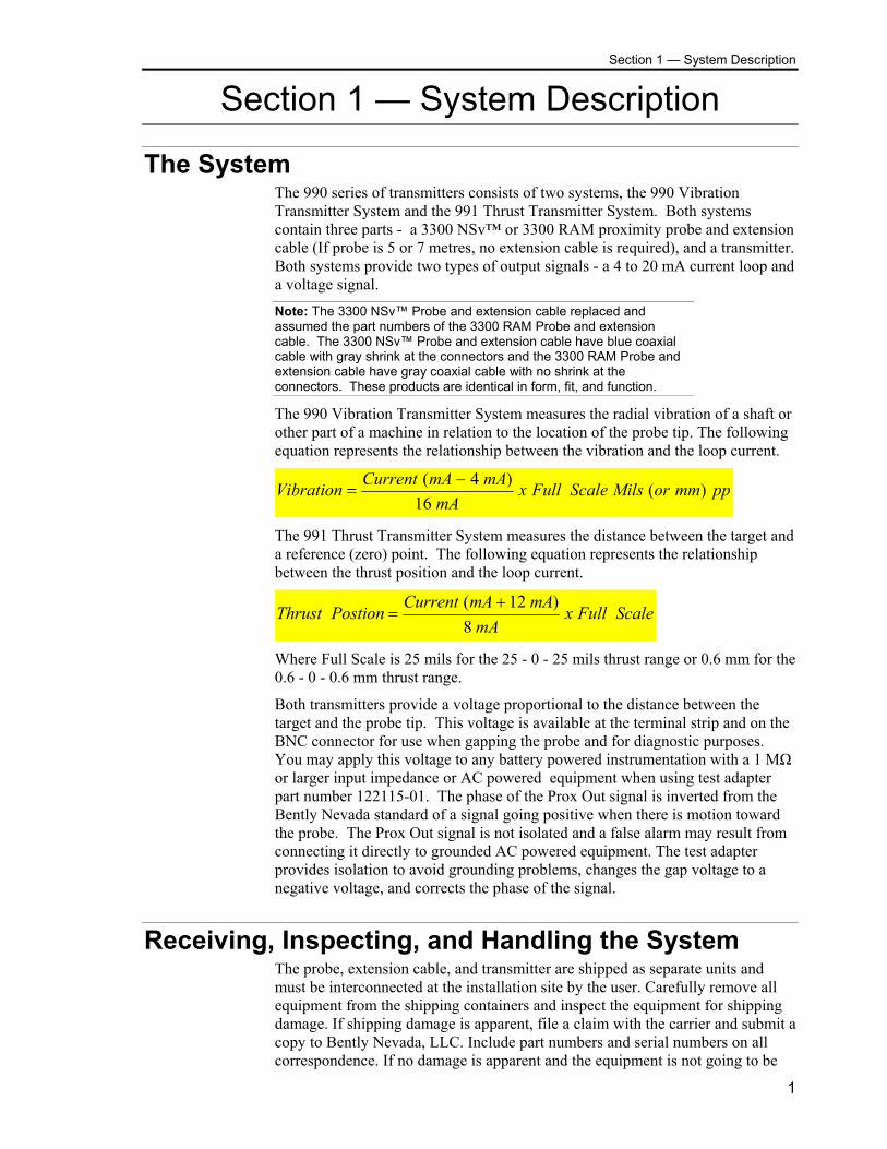
The System The 990 series of transmitters consists of two systems, the 990 Vibration Transmitter System and the 991 Thrust Transmitter System. Both systems contain three parts - a 3300 NSv™ or 3300 RAM proximity probe and extension cable (If probe is 5 or 7 metres, no extension cable is required), and a transmitter. Both systems provide two types of output signals - a 4 to 20 mA current loop and a voltage signal.
Note: The 3300 NSv™ Probe and extension cable replaced and assumed the part numbers of the 3300 RAM Probe and extension cable. The 3300 NSv™ Probe and extension cable have blue coaxial cable with gray shrink at the connectors and the 3300 RAM Probe and extension cable have gray coaxial cable with no shrink at the connectors. These products are identical in form, fit, and function.
The 990 Vibration Transmitter System measures the radial vibration of a shaft or other part of a machine in relation to the location of the probe tip. The following equation represents the relationship between the vibration and the loop current.
ppmmorMilsScaleFullxmA
mAmACurrentVibration )(16
)4( −=
The 991 Thrust Transmitter System measures the distance between the target and a reference (zero) point. The following equation represents the relationship between the thrust position and the loop current.
ScaleFullxmA
mAmACurrentPostionThrust
8)12( +
=
Where Full Scale is 25 mils for the 25 - 0 - 25 mils thrust range or 0.6 mm for the 0.6 - 0 - 0.6 mm thrust range.
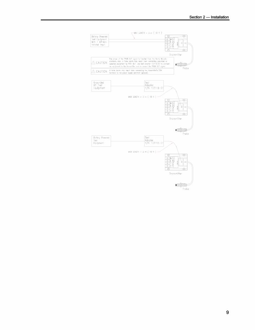
Both transmitters provide a voltage proportional to the distance between the target and the probe tip. This voltage is available at the terminal strip and on the BNC connector for use when gapping the probe and for diagnostic purposes. You may apply this voltage to any battery powered instrumentation with a 1 MΩ or larger input impedance or AC powered equipment when using test adapter part number 122115-01. The phase of the Prox Out signal is inverted from the Bently Nevada standard of a signal going positive when there is motion toward the probe. The Prox Out signal is not isolated and a false alarm may result from connecting it directly to grounded AC powered equipment. The test adapter provides isolation to avoid grounding problems, changes the gap voltage to a negative voltage, and corrects the phase of the signal.
Receiving, Inspecting, and Handling the System The probe, extension cable, and transmitter are shipped as separate units and must be interconnected at the installation site by the user. Carefully remove all equipment from the shipping containers and inspect the equipment for shipping damage. If shipping damage is apparent, file a claim with the carrier and submit a copy to Bently Nevada, LLC. Include part numbers and serial numbers on all correspondence. If no damage is apparent and the equipment is not going to be
1

990 Transmitter System Manual
used immediately, return the equipment to the shipping containers and reseal until ready for use.
Store the equipment in an environment free from potentially damaging conditions such as high temperature, excessive humidity, or a corrosive atmosphere. See pages 27, 30, and 31 for environmental specifications.
2
Section 2 — Installation
Section 2 — Installation This section contains a checklist of items that you must consider when you install the 990 transmitter system. For detailed information about designing installations for specific applications, refer to document AN013. For more information about the specifications for this transducer, refer to page 27 of this manual or to document 157771.
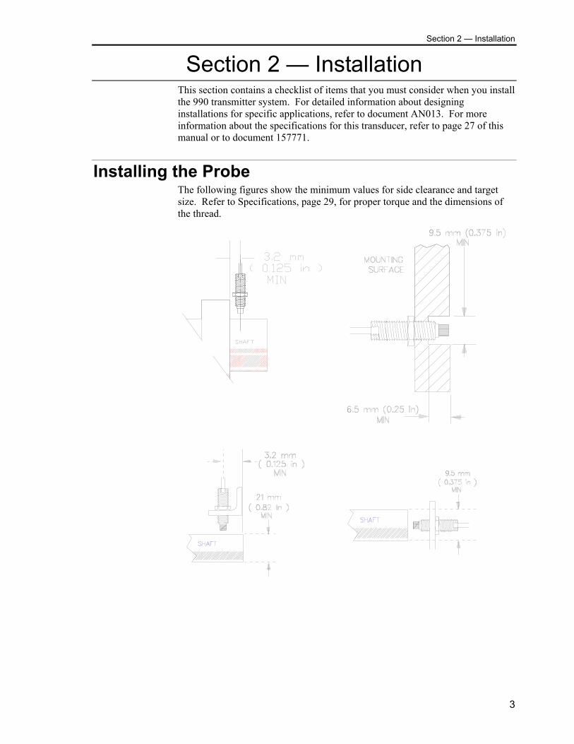
Installing the Probe The following figures show the minimum values for side clearance and target size. Refer to Specifications, page 29, for proper torque and the dimensions of the thread.
3
990 Transmitter System Manual
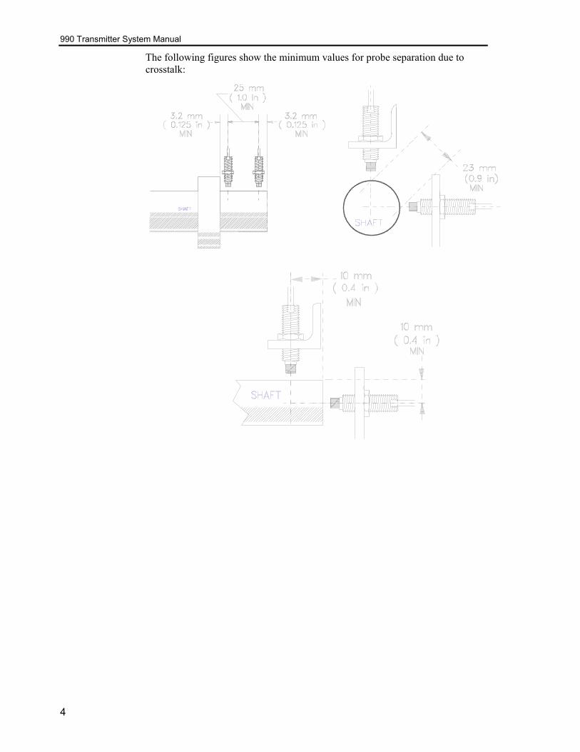
The following figures show the minimum values for probe separation due to crosstalk:
4
Section 2 — Installation
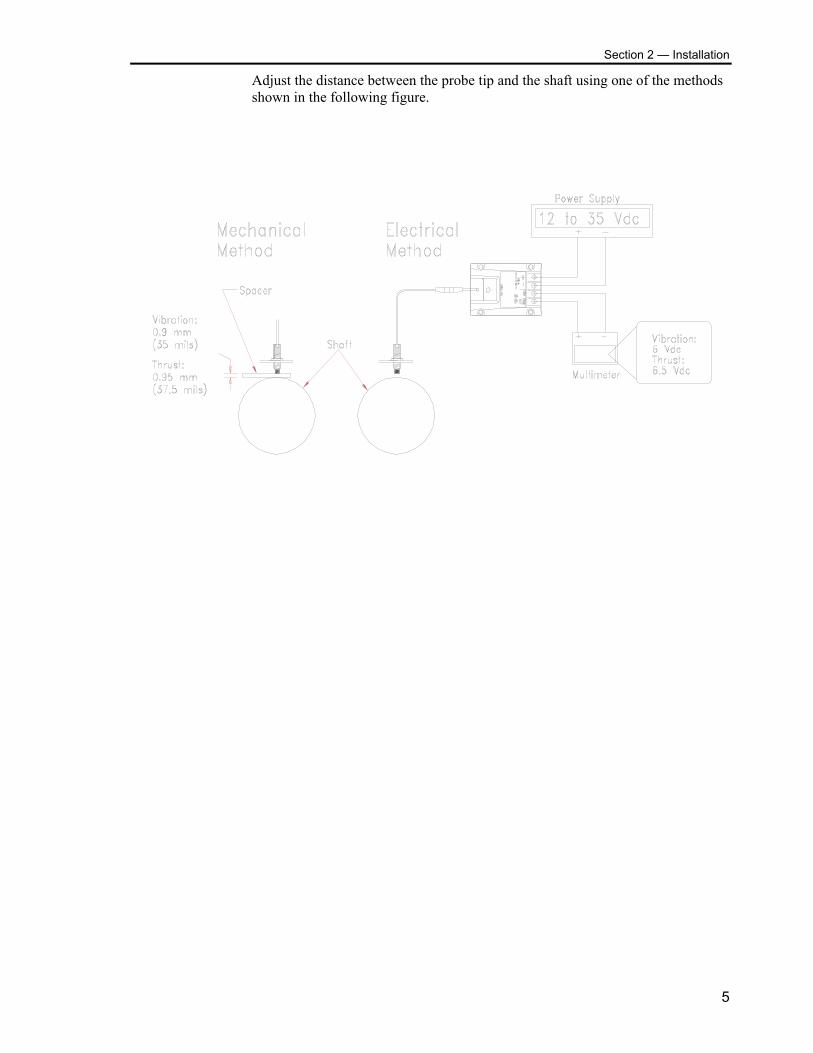
Adjust the distance between the probe tip and the shaft using one of the methods shown in the following figure.
5

990 Transmitter System Manual
Mounting the transmitter Mount the transmitter in a location that is compatible with its environmental specifications. Refer to page 27 for the environmental specifications for the transmitter. The following figure shows the dimensions of the transmitter.
Routing the Extension Cable and Field Wiring Route the extension cable using the following guidelines.
Check that the Transmitter, extension cable, and probe belong to the same system. The allowable systems are:
Transmitter Probe Length Cable Length
5 metre 5 metre None
5 metre 1.0 metre 4.0 metre
5 metre 0.5 metre 4.5 metre
7 metre 7 metre None
7 metre 1.0 metre 6.0
7 metre 0.5 metre 6.5
• Secure the extension cable to supporting surfaces by using mounting clips or similar devices.
• Identify both ends of the extension cable by inserting labels under the clear Teflon sleeves and applying heat to shrink the tubing.
• Secure coaxial connectors between the extension cable and the proximity probe (Refer to Connector-to-Connector Torque Requirements on Page 31).
• Insulate the connection between the probe lead and the extension cable by wrapping the connector with Teflon tape.
6
Section 2 — Installation
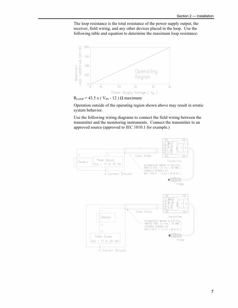
The loop resistance is the total resistance of the power supply output, the receiver, field wiring, and any other devices placed in the loop. Use the following table and equation to determine the maximum loop resistance:
RLOOP = 43.5 x ( VPS - 12 ) Ω maximum
Operation outside of the operating region shown above may result in erratic system behavior.
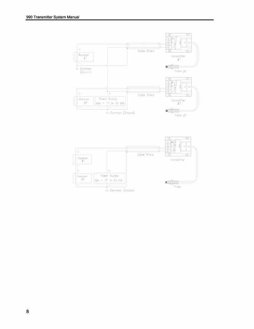
Use the following wiring diagrams to connect the field wiring between the transmitter and the monitoring instruments. Connect the transmitter to an approved source (approved to IEC 1010.1 for example.)
7
990 Transmitter System Manual 990 Transmitter System Manual
8
8
Section 2 — Installation Section 2 — Installation
9
9

990 Transmitter System Manual
10
Section 3 — Maintenance and Troubleshooting
Section 3 — Maintenance and Troubleshooting
Maintenance This section shows how to verify that the system is operating properly, adjust the system, and identify parts of the system that are not working properly.
The transmitter system does not require verification at regular intervals. You should, however, verify operation by using the scale factor verification on page 12 if any of the following conditions occur:
• components of the system are replaced or disturbed • the performance of the system changes or becomes erratic • you suspect that the transmitter is not calibrated correctly.
The adjustment procedures on pages 14 thru 17 are included for your information. For target materials other than 4140 steel and for other special applications, contact your local Bently Nevada office.
The scale factor verification procedure, the scale factor adjustment procedure, and the zero/span adjustment procedure require the following instruments:
digital multimeter (2) spindle micrometer power supply
CAUTION Electrostatic discharge on the exposed calibration resistor terminals can cause the accuracy of the system to go out of specification, or cause the system to fail. Use appropriate precautions for handling static sensitive devices.
The adjustment procedure also requires the following items:
variable resistor, 0 to 100 kΩ vulcanizing compound (for example, Dow 3110 RTV) soldering iron (with grounded tip) and soldering supplies
11
990 Transmitter System Manual
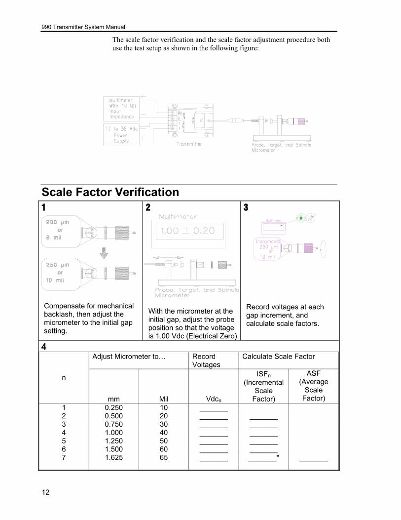
The scale factor verification and the scale factor adjustment procedure both use the test setup as shown in the following figure:
Scale Factor Verification 1
Compensate for mechanical backlash, then adjust the micrometer to the initial gap setting.
2
With the micrometer at the initial gap, adjust the probe position so that the voltage is 1.00 Vdc (Electrical Zero).
3
Record voltages at each gap increment, and calculate scale factors.
4
Adjust Micrometer to… Record Voltages
Calculate Scale Factor
n
mm Mil Vdcn
ISFn (Incremental
Scale Factor)
ASF (Average
Scale Factor)
1 0.250 10 _______ 2 0.500 20 _______ _______ 3 0.750 30 _______ _______ 4 1.000 40 _______ _______ 5 1.250 50 _______ _______ 6 1.500 60 _______ _______ 7
1.625 65 _______ _______* _______
12
Section 3 — Maintenance and Troubleshooting
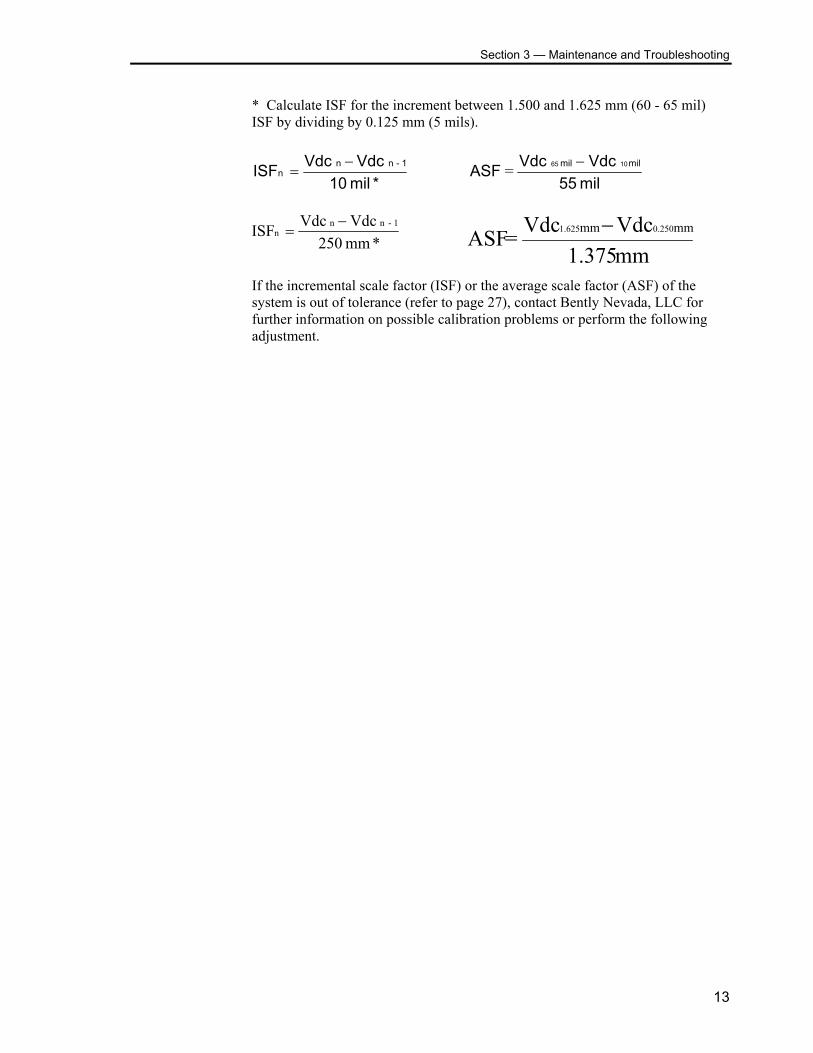
* Calculate ISF for the increment between 1.500 and 1.625 mm (60 - 65 mil) ISF by dividing by 0.125 mm (5 mils).
*mil 10Vdc Vdc ISF 1-nn
n−
=mil 55 Vdc Vdc ASF milmil 1065 −=
13
mm 1.375 Vdc Vdc ASF mm mm 0.2501.625 −=
m250
VdcISF nn
−=
Vdc 1-n
m *
If the incremental scale factor (ISF) or the average scale factor (ASF) of the system is out of tolerance (refer to page 27), contact Bently Nevada, LLC for further information on possible calibration problems or perform the following adjustment.
990 Transmitter System Manual
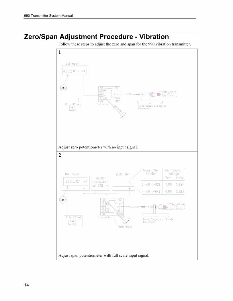
Zero/Span Adjustment Procedure - Vibration Follow these steps to adjust the zero and span for the 990 vibration transmitter.
1
Adjust zero potentiometer with no input signal.
2
Adjust span potentiometer with full scale input signal.
14
Section 3 — Maintenance and Troubleshooting
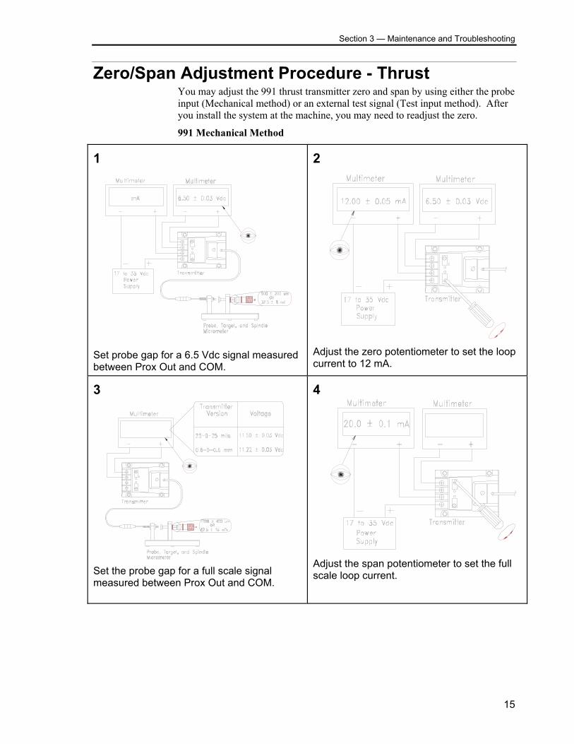
Zero/Span Adjustment Procedure - Thrust You may adjust the 991 thrust transmitter zero and span by using either the probe input (Mechanical method) or an external test signal (Test input method). After you install the system at the machine, you may need to readjust the zero.
991 Mechanical Method 1
Set probe gap for a 6.5 Vdc signal measured between Prox Out and COM.
2
Adjust the zero potentiometer to set the loop current to 12 mA.
3
Set the probe gap for a full scale signal measured between Prox Out and COM.
4
Adjust the span potentiometer to set the full scale loop current.
15
990 Transmitter System Manual
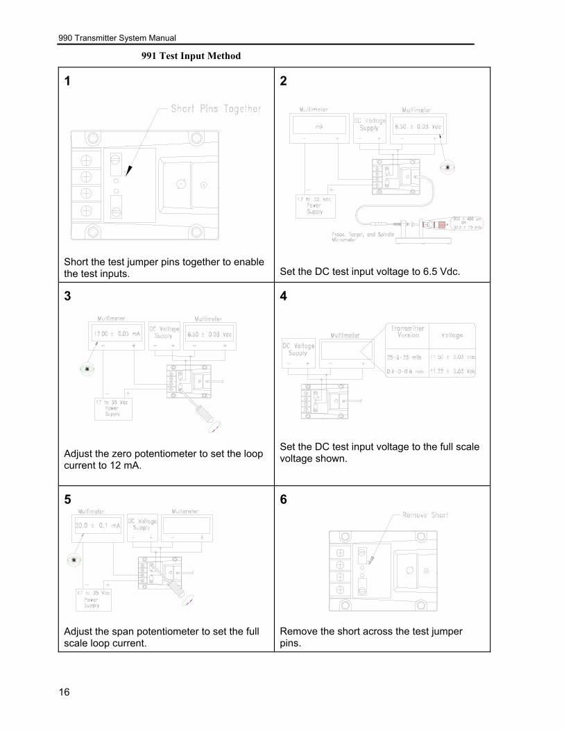
991 Test Input Method 1
Short the test jumper pins together to enable the test inputs.
2
Set the DC test input voltage to 6.5 Vdc. 3
Adjust the zero potentiometer to set the loop current to 12 mA.
4
Set the DC test input voltage to the full scale voltage shown.
5
Adjust the span potentiometer to set the full scale loop current.
6
Remove the short across the test jumper pins.
16
Section 3 — Maintenance and Troubleshooting
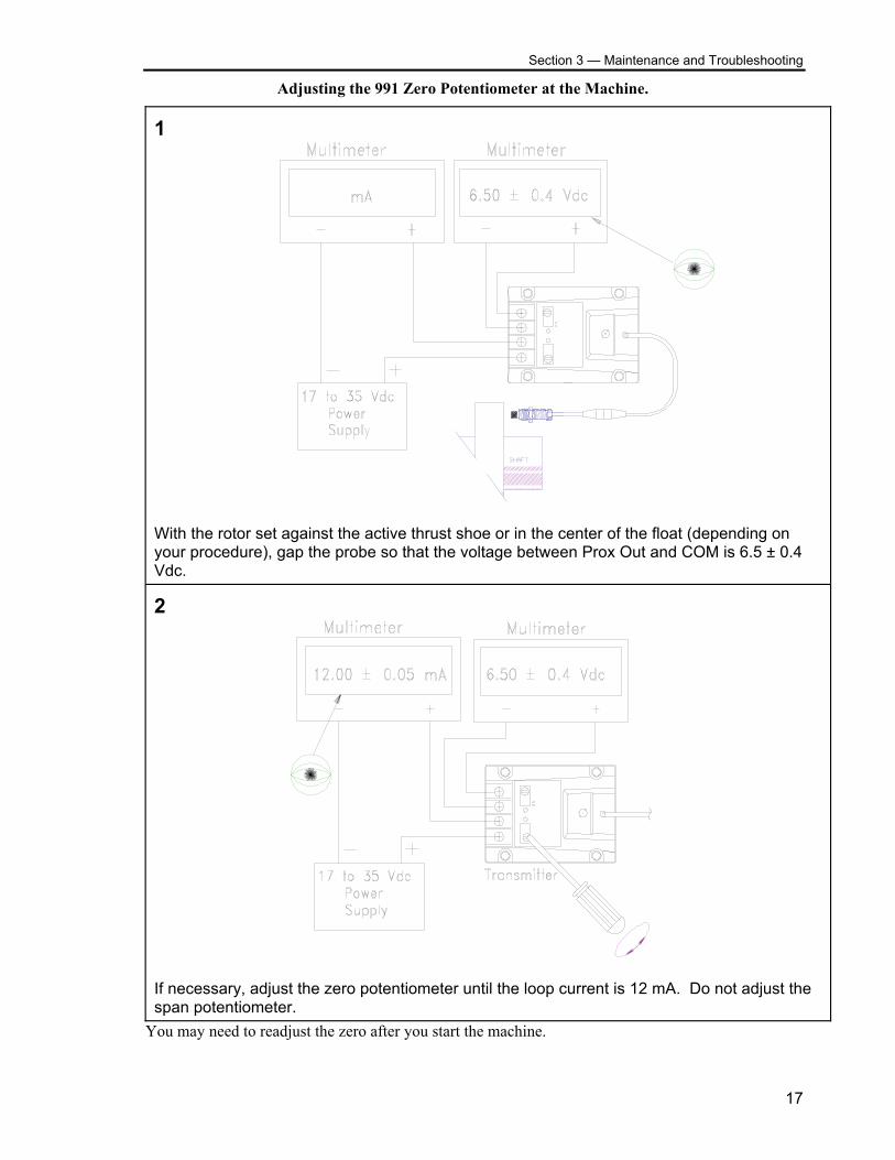
Adjusting the 991 Zero Potentiometer at the Machine. 1
With the rotor set against the active thrust shoe or in the center of the float (depending on your procedure), gap the probe so that the voltage between Prox Out and COM is 6.5 ± 0.4 Vdc. 2
If necessary, adjust the zero potentiometer until the loop current is 12 mA. Do not adjust the span potentiometer.
You may need to readjust the zero after you start the machine.
17
990 Transmitter System Manual
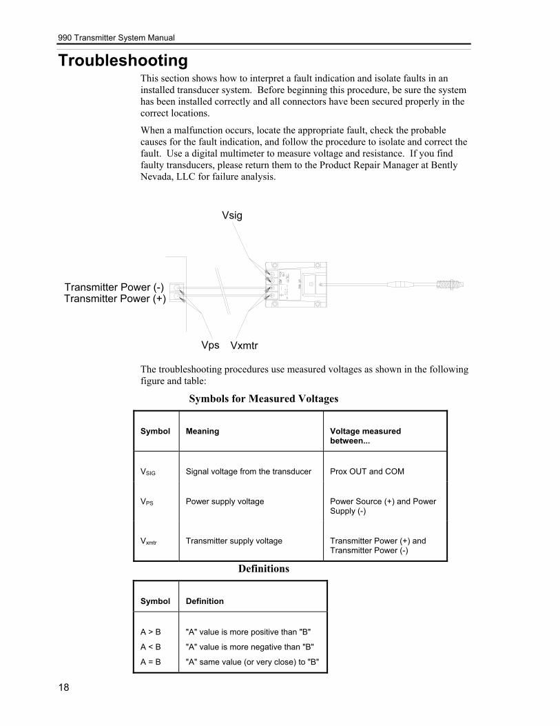
Troubleshooting This section shows how to interpret a fault indication and isolate faults in an installed transducer system. Before beginning this procedure, be sure the system has been installed correctly and all connectors have been secured properly in the correct locations.
When a malfunction occurs, locate the appropriate fault, check the probable causes for the fault indication, and follow the procedure to isolate and correct the fault. Use a digital multimeter to measure voltage and resistance. If you find faulty transducers, please return them to the Product Repair Manager at Bently Nevada, LLC for failure analysis.
Vxmtr
Vsig
Transmitter Power (-)Transmitter Power (+)
Vps
The troubleshooting procedures use measured voltages as shown in the following figure and table:
Symbols for Measured Voltages
Symbol
Meaning
Voltage measured between...
VSIG
Signal voltage from the transducer
Prox OUT and COM
VPS
Power supply voltage
Power Source (+) and Power Supply (-)
Vxmtr
Transmitter supply voltage
Transmitter Power (+) and Transmitter Power (-)
Definitions
Symbol
Definition
A > B
A < B
A = B
"A" value is more positive than "B"
"A" value is more negative than "B"
"A" same value (or very close) to "B"
18
Section 3 — Maintenance and Troubleshooting
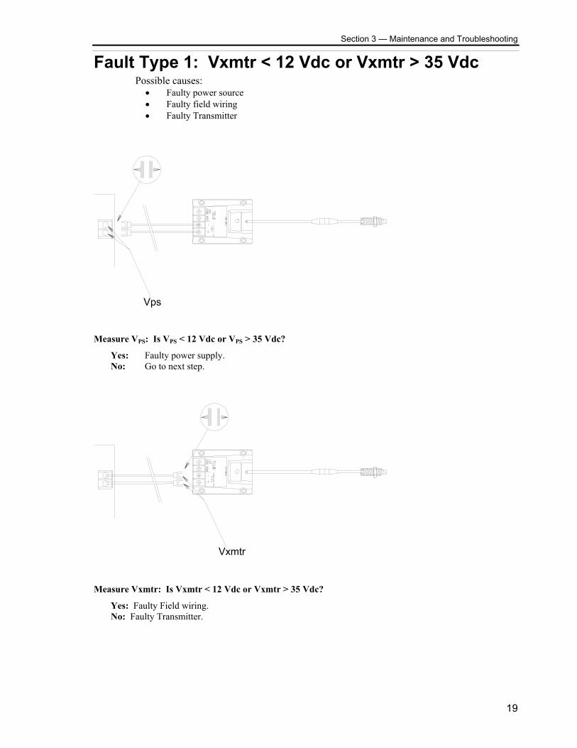
Fault Type 1: Vxmtr < 12 Vdc or Vxmtr > 35 Vdc Possible causes:
• Faulty power source • Faulty field wiring • Faulty Transmitter
Vps
Measure VPS: Is VPS < 12 Vdc or VPS > 35 Vdc?
Yes: Faulty power supply. No: Go to next step.
Vxmtr
Measure Vxmtr: Is Vxmtr < 12 Vdc or Vxmtr > 35 Vdc?
Yes: Faulty Field wiring. No: Faulty Transmitter.
19
990 Transmitter System Manual
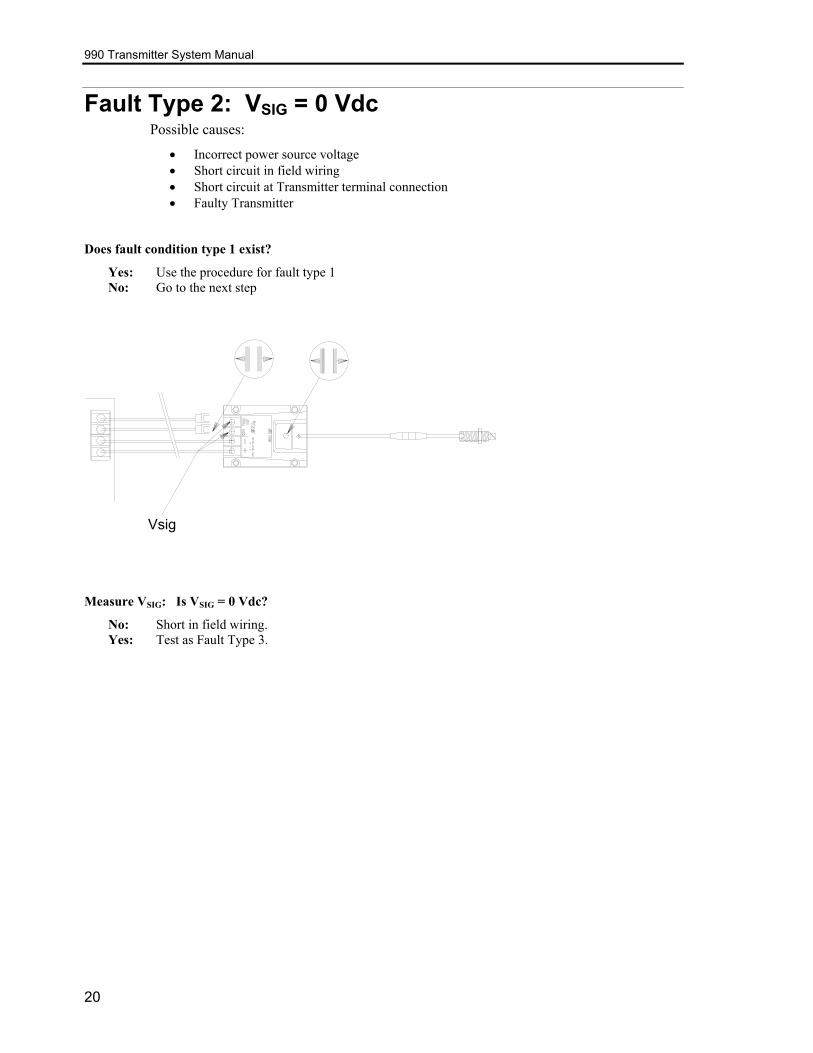
Fault Type 2: VSIG = 0 Vdc Possible causes:
• Incorrect power source voltage • Short circuit in field wiring • Short circuit at Transmitter terminal connection • Faulty Transmitter
Does fault condition type 1 exist?
Yes: Use the procedure for fault type 1 No: Go to the next step
Vsig
Measure VSIG: Is VSIG = 0 Vdc?
No: Short in field wiring. Yes: Test as Fault Type 3.
20
Section 3 — Maintenance and Troubleshooting
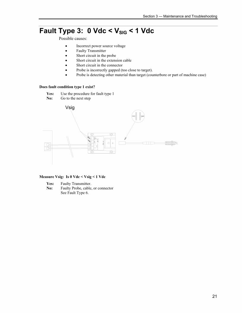
Fault Type 3: 0 Vdc < VSIG < 1 Vdc Possible causes:
• Incorrect power source voltage • Faulty Transmitter • Short circuit in the probe • Short circuit in the extension cable • Short circuit in the connector • Probe is incorrectly gapped (too close to target). • Probe is detecting other material than target (counterbore or part of machine case)
Does fault condition type 1 exist?
Yes: Use the procedure for fault type 1 No: Go to the next step
Vsig
Measure Vsig: Is 0 Vdc < Vsig < 1 Vdc
Yes: Faulty Transmitter. No: Faulty Probe, cable, or connector See Fault Type 6.
21
990 Transmitter System Manual
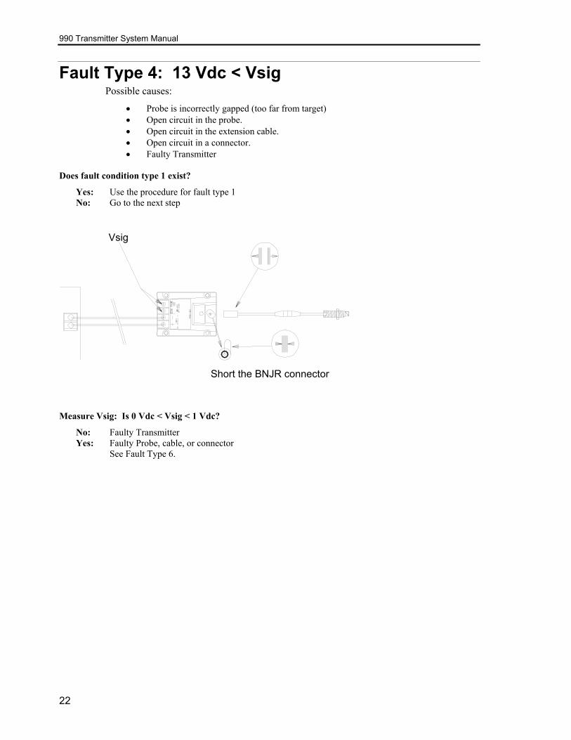
Fault Type 4: 13 Vdc < Vsig Possible causes:
• Probe is incorrectly gapped (too far from target) • Open circuit in the probe. • Open circuit in the extension cable. • Open circuit in a connector. • Faulty Transmitter
Does fault condition type 1 exist?
Yes: Use the procedure for fault type 1 No: Go to the next step
Vsig
Short the BNJR connector
Measure Vsig: Is 0 Vdc < Vsig < 1 Vdc?
No: Faulty Transmitter Yes: Faulty Probe, cable, or connector See Fault Type 6.
22
Section 3 — Maintenance and Troubleshooting
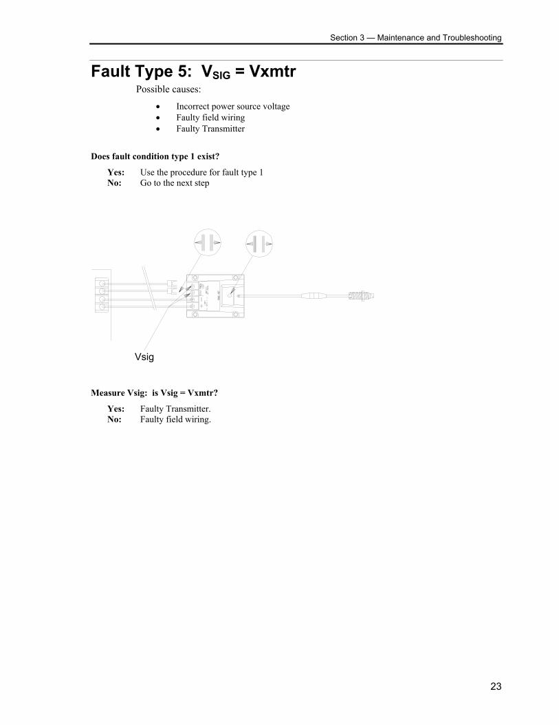
Fault Type 5: VSIG = Vxmtr Possible causes:
• Incorrect power source voltage • Faulty field wiring • Faulty Transmitter
Does fault condition type 1 exist?
Yes: Use the procedure for fault type 1 No: Go to the next step
Vsig
Measure Vsig: is Vsig = Vxmtr?
Yes: Faulty Transmitter. No: Faulty field wiring.
23
990 Transmitter System Manual
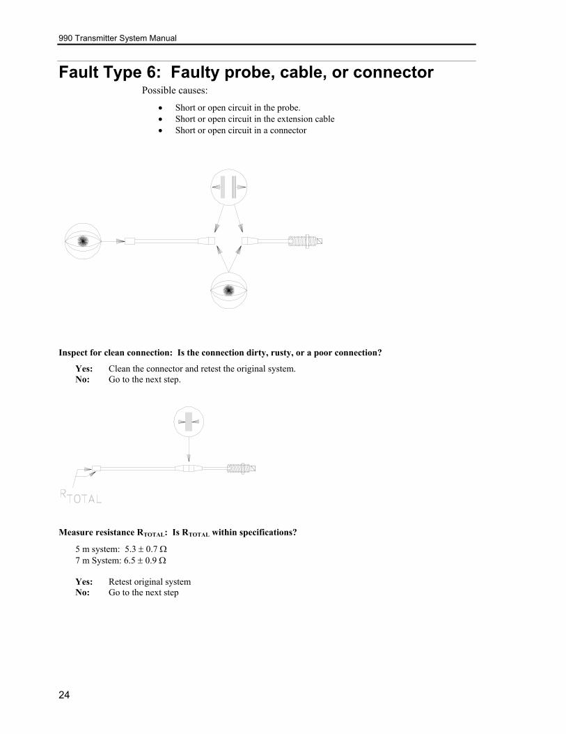
Fault Type 6: Faulty probe, cable, or connector Possible causes:
• Short or open circuit in the probe. • Short or open circuit in the extension cable • Short or open circuit in a connector
Inspect for clean connection: Is the connection dirty, rusty, or a poor connection?
Yes: Clean the connector and retest the original system. No: Go to the next step.
Measure resistance RTOTAL: Is RTOTAL within specifications?
5 m system: 5.3 ± 0.7 Ω 7 m System: 6.5 ± 0.9 Ω Yes: Retest original system No: Go to the next step
24
Section 3 — Maintenance and Troubleshooting
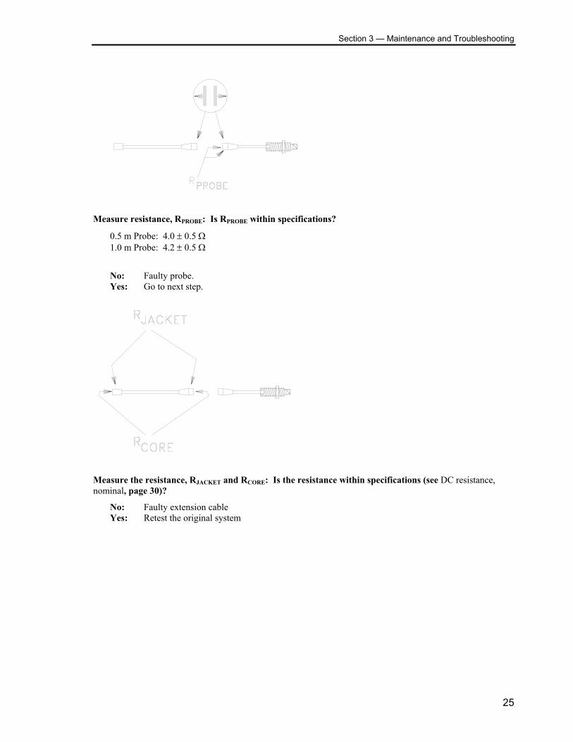
Measure resistance, RPROBE: Is RPROBE within specifications?
0.5 m Probe: 4.0 ± 0.5 Ω 1.0 m Probe: 4.2 ± 0.5 Ω
No: Faulty probe. Yes: Go to next step.
Measure the resistance, RJACKET and RCORE: Is the resistance within specifications (see DC resistance, nominal, page 30)?
No: Faulty extension cable Yes: Retest the original system
25
990 Transmitter System Manual
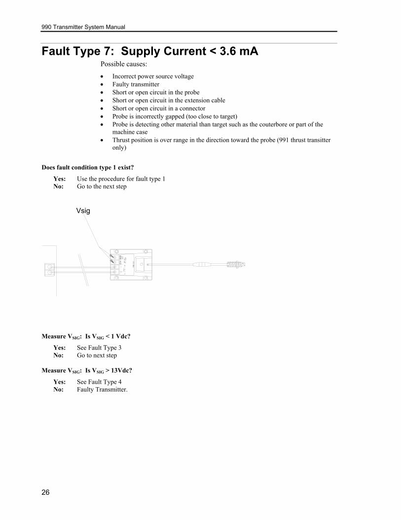
Fault Type 7: Supply Current < 3.6 mA Possible causes:
• Incorrect power source voltage • Faulty transmitter • Short or open circuit in the probe • Short or open circuit in the extension cable • Short or open circuit in a connector • Probe is incorrectly gapped (too close to target) • Probe is detecting other material than target such as the couterbore or part of the
machine case • Thrust position is over range in the direction toward the probe (991 thrust transitter
only)
Does fault condition type 1 exist?
Yes: Use the procedure for fault type 1 No: Go to the next step
Vsig
Measure VSIG: Is VSIG < 1 Vdc?
Yes: See Fault Type 3 No: Go to next step
Measure VSIG: Is VSIG > 13Vdc?
Yes: See Fault Type 4 No: Faulty Transmitter.
26
Section 4 — Specifications
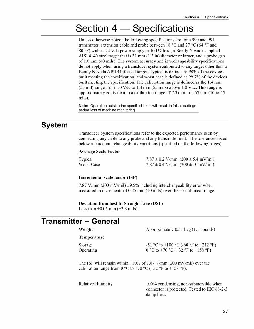
Section 4 — Specifications Unless otherwise noted, the following specifications are for a 990 and 991 transmitter, extension cable and probe between 18 °C and 27 °C (64 °F and 80 °F) with a -24 Vdc power supply, a 10 kΩ load, a Bently Nevada supplied AISI 4140 steel target that is 31 mm (1.2 in) diameter or larger, and a probe gap of 1.0 mm (40 mils). The system accuracy and interchangeability specifications do not apply when using a transducer system calibrated to any target other than a Bently Nevada AISI 4140 steel target. Typical is defined as 90% of the devices built meeting the specification, and worst case is defined as 99.7% of the devices built meeting the specification. The calibration range is defined as the 1.4 mm (55 mil) range from 1.0 Vdc to 1.4 mm (55 mils) above 1.0 Vdc. This range is approximately equivalent to a calibration range of .25 mm to 1.65 mm (10 to 65 mils).
Note: Operation outside the specified limits will result in false readings and/or loss of machine monitoring.
System Transducer System specifications refer to the expected performance seen by connecting any cable to any probe and any transmitter unit. The tolerances listed below include interchangeability variations (specified on the following pages).
Average Scale Factor
Typical 7.87 ± 0.2 V/mm (200 ± 5.4 mV/mil) Worst Case 7.87 ± 0.4 V/mm (200 ± 10 mV/mil)
Incremental scale factor (ISF)
7.87 V/mm (200 mV/mil) ±9.5% including interchangeability error when measured in increments of 0.25 mm (10 mils) over the 55 mil linear range
Deviation from best fit Straight Line (DSL) Less than ±0.06 mm (±2.3 mils).
Transmitter -- General Weight Approximately 0.514 kg (1.1 pounds)
Temperature
Storage -51 °C to +100 °C (-60 °F to +212 °F) Operating 0 °C to +70 °C (+32 °F to +158 °F)
The ISF will remain within ±10% of 7.87 V/mm (200 mV/mil) over the calibration range from 0 °C to +70 °C (+32 °F to +158 °F).
Relative Humidity 100% condensing, non-submersible when connector is protected. Tested to IEC 68-2-3 damp heat.
27
990 Transmitter System Manual
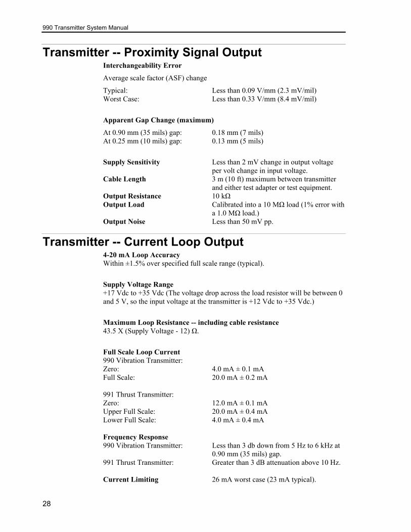
Transmitter -- Proximity Signal Output Interchangeability Error
Average scale factor (ASF) change
Typical: Less than 0.09 V/mm (2.3 mV/mil) Worst Case: Less than 0.33 V/mm (8.4 mV/mil)
Apparent Gap Change (maximum)
At 0.90 mm (35 mils) gap: 0.18 mm (7 mils) At 0.25 mm (10 mils) gap: 0.13 mm (5 mils)
Supply Sensitivity Less than 2 mV change in output voltage per volt change in input voltage.
Cable Length 3 m (10 ft) maximum between transmitter and either test adapter or test equipment.
Output Resistance 10 kΩ Output Load Calibrated into a 10 MΩ load (1% error with
a 1.0 MΩ load.) Output Noise Less than 50 mV pp.
Transmitter -- Current Loop Output 4-20 mA Loop Accuracy Within ±1.5% over specified full scale range (typical).
Supply Voltage Range +17 Vdc to +35 Vdc (The voltage drop across the load resistor will be between 0 and 5 V, so the input voltage at the transmitter is +12 Vdc to +35 Vdc.)
Maximum Loop Resistance -- including cable resistance 43.5 X (Supply Voltage - 12) Ω.
Full Scale Loop Current 990 Vibration Transmitter: Zero: 4.0 mA ± 0.1 mA Full Scale: 20.0 mA ± 0.2 mA 991 Thrust Transmitter: Zero: 12.0 mA ± 0.1 mA Upper Full Scale: 20.0 mA ± 0.4 mA Lower Full Scale: 4.0 mA ± 0.4 mA Frequency Response 990 Vibration Transmitter: Less than 3 db down from 5 Hz to 6 kHz at
0.90 mm (35 mils) gap. 991 Thrust Transmitter: Greater than 3 dB attenuation above 10 Hz. Current Limiting 26 mA worst case (23 mA typical).
28
Section 4 — Specifications
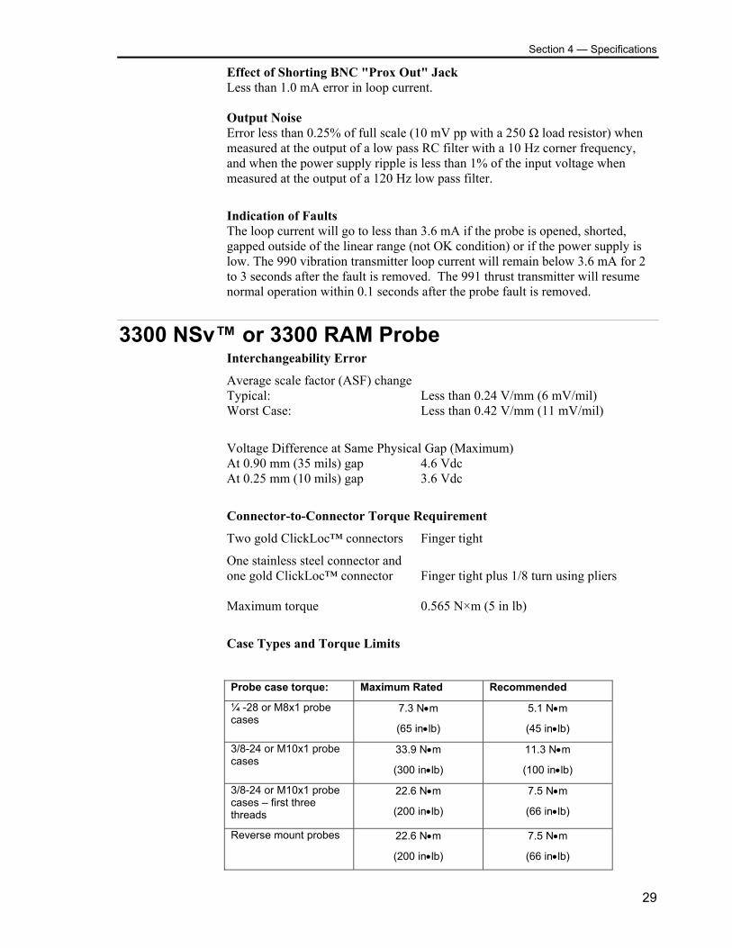
Effect of Shorting BNC "Prox Out" Jack Less than 1.0 mA error in loop current. Output Noise Error less than 0.25% of full scale (10 mV pp with a 250 Ω load resistor) when measured at the output of a low pass RC filter with a 10 Hz corner frequency, and when the power supply ripple is less than 1% of the input voltage when measured at the output of a 120 Hz low pass filter.
Indication of Faults The loop current will go to less than 3.6 mA if the probe is opened, shorted, gapped outside of the linear range (not OK condition) or if the power supply is low. The 990 vibration transmitter loop current will remain below 3.6 mA for 2 to 3 seconds after the fault is removed. The 991 thrust transmitter will resume normal operation within 0.1 seconds after the probe fault is removed.
3300 NSv™ or 3300 RAM Probe Interchangeability Error
Average scale factor (ASF) change Typical: Less than 0.24 V/mm (6 mV/mil) Worst Case: Less than 0.42 V/mm (11 mV/mil)
Voltage Difference at Same Physical Gap (Maximum) At 0.90 mm (35 mils) gap 4.6 Vdc At 0.25 mm (10 mils) gap 3.6 Vdc
Connector-to-Connector Torque Requirement
Two gold ClickLoc™ connectors Finger tight
One stainless steel connector and one gold ClickLoc™ connector Finger tight plus 1/8 turn using pliers Maximum torque 0.565 N×m (5 in lb)
Case Types and Torque Limits
Probe case torque: Maximum Rated Recommended
¼ -28 or M8x1 probe cases
7.3 N•m
(65 in•lb)
5.1 N•m
(45 in•lb)
3/8-24 or M10x1 probe cases
33.9 N•m
(300 in•lb)
11.3 N•m
(100 in•lb)
3/8-24 or M10x1 probe cases – first three threads
22.6 N•m
(200 in•lb)
7.5 N•m
(66 in•lb)
Reverse mount probes 22.6 N•m
(200 in•lb)
7.5 N•m
(66 in•lb)
29
990 Transmitter System Manual
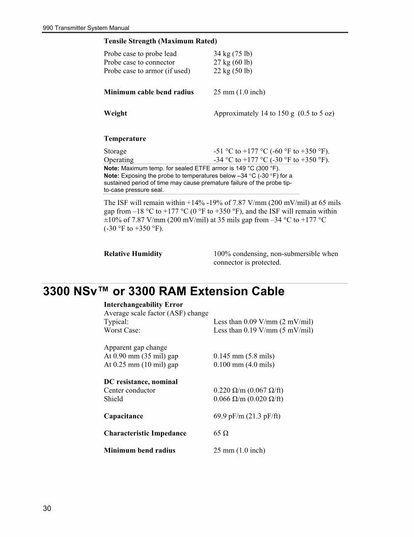
Tensile Strength (Maximum Rated)
Probe case to probe lead 34 kg (75 lb) Probe case to connector 27 kg (60 lb) Probe case to armor (if used) 22 kg (50 lb)
Minimum cable bend radius 25 mm (1.0 inch)
Weight Approximately 14 to 150 g (0.5 to 5 oz)
Temperature
Storage -51 °C to +177 °C (-60 °F to +350 °F). Operating -34 °C to +177 °C (-30 °F to +350 °F). Note: Maximum temp. for sealed ETFE armor is 149 °C (300 °F). Note: Exposing the probe to temperatures below –34 °C (-30 °F) for a sustained period of time may cause premature failure of the probe tip-to-case pressure seal.
The ISF will remain within +14% -19% of 7.87 V/mm (200 mV/mil) at 65 mils gap from –18 °C to +177 °C (0 °F to +350 °F), and the ISF will remain within ±10% of 7.87 V/mm (200 mV/mil) at 35 mils gap from –34 °C to +177 °C (-30 °F to +350 °F).
Relative Humidity 100% condensing, non-submersible when connector is protected.
3300 NSv™ or 3300 RAM Extension Cable Interchangeability Error Average scale factor (ASF) change Typical: Less than 0.09 V/mm (2 mV/mil) Worst Case: Less than 0.19 V/mm (5 mV/mil) Apparent gap change At 0.90 mm (35 mil) gap 0.145 mm (5.8 mils) At 0.25 mm (10 mil) gap 0.100 mm (4.0 mils) DC resistance, nominal Center conductor 0.220 Ω/m (0.067 Ω/ft) Shield 0.066 Ω/m (0.020 Ω/ft) Capacitance 69.9 pF/m (21.3 pF/ft) Characteristic Impedance 65 Ω Minimum bend radius 25 mm (1.0 inch)
30
Section 4 — Specifications
Connector-to-Connector Torque Requirement Two gold ClickLoc™ connectors Finger tight One stainless steel connector and one gold ClickLoc™ connector Finger tight plus 1/8 turn using pliers Maximum torque 0.565 N×m (5 in lb) Weight No Armor 45 g/m (0.5 oz/ft) With Armor 65 g/m (0.7 oz/ft) Temperature Storage -51 °C to +177 °C (-60 °F to +350 °F) Operating -51 °C to +177 °C (-60 °F to +350 °F) The ISF will remain within +14% -19% of 7.87 V/mm (200 mV/mil) at 65 mils gap from –18 °C to +177 °C (0 °F to +350 °F), and the ISF will remain within ±10% of 7.87 V/mm (200 mV/mil) at 35 mils gap from –34 °C to +177 °C (-30 °F to +350 °F).
Relative Humidity 100% condensing, non-submersible when connector is protected.
31