Embed Size (px)
Citation preview

2 3
1 3
12 10
98015 series, 3/2 Direct solenoid actuated poppet valve
11/18en 5.4.369.01
Our policy is one of continued research and development. We therefore reserve the right to amend, without notice, the specifications given in this document. (2004 - 5146e) © 2014 Norgren GmbH
Medium:Neutral or aggressive, gaseous fluids which do not damage the product or affect the function (e.g. compressed air, nitrogen). Based on ISO 8573-1-2010 classification 1-2-3.Operation:Direct solenoid operatedpoppet valveOperating pressure:0 ... 10 bar (0 ... 145 psi) Orifice:8 mm
Port size:G1/4, G1/4 NAMUR, 1/4 NPT, 1/4 NPT NAMUR, G1/2, G1/2 NAMUR, 1/2 NPT, 1/2 NPT NAMUR NAMUR Interface with integrated recirculation from the exhaust air to the acutator sping chamberFlow direction:OptionalMounting position:Any, but preferably with solenoid vertical
Ambient/Media temperature:-40 ... +60°C (-40 ... +140°F) -25 ... +60°C (-13 ... +140°F)(SIL version) Depending on solenoid system. Air supply must be dry enough to avoid ice formation at temperatures below +2°C (35°F). For outdoor installations all connections must be protected against the penetration of moisture and a solenoid with IP66 protection must be used!
Materials:Body: Aluminium anodized(suitable for high humidity, sulphuric, sodium chloride or ammonia environments),brass 2.0401 (Ms 58),stainless steel 1.4404 (316 L)Seals: NBR
Flow conversion:Cv US Gallon/min (water) = l/min (air) x 0,001Kv m³/h (water) =l/min (air) x 0,000906
Technical features
> 1/4“ & 1/2“ (ISO G or NPT) Inline & NAMUR
> Main application: Single acting actuators
> Approval based on type examination DGRL 97/23/EG and IEC 61 508, multichannel up to SIL 3
> Optional add-on manual override or inductive limit switches on request
> Suited for outdoor use with critical environment conditions
> Variable valve solenoid combination
Technical data Seals: NBR -40 ... +60°C (-40 ... +140°F) / IEC 61508: -25 ... +60°C (-13 ... +140°F). Housing: Aluminium anodizedSymbol Port size
1, 3 2 (3)Flow (l/min) *1)1 » 2 2 » 3
Flow (l/min) *2)1 » 2 2 » 3
Operating pressure (bar) (psi)
DrawingNo.
Model *3)
G1/4, G1/2 G1/4 NAMUR 1100 1300 2900 3400 0 ... 10 0 ... 145 1 9801505
1/4 NPT, 1/2 NPT 1/4 NPT NAMUR 1100 1300 2900 3400 0 ... 10 0 ... 145 1 9801515
Housing: Stainless steelSymbol Port size Flow (l/min) *1)
1 » 2 2 » 3 Flow (l/min) *2)1 » 2 2 » 3
Operating pressure (bar) (psi)
DrawingNo.
Model *3)
3
2 21012
1012
1012
1 3
3
2
1 3
3
2
1 3
3
1012
1012
1012
1 3
3
2
1 3
3
2
1 3
G1/2 1200 1300 3100 3400 0 ... 10 0 ... 145 2 9801755
1/2 NPT 1200 1300 3100 3400 0 ... 10 0 ... 145 2 9801765
Housing: BrassSymbol Port size Flow (l/min) *1)
1 » 2 2 » 3 Flow (l/min) *2)1 » 2 2 » 3
Operating pressure (bar) (psi)
DrawingNo.
Model *3)
3
2 21012
1012
1012
1 3
3
2
1 3
3
2
1 3
3
1012
1012
1012
1 3
3
2
1 3
3
2
1 3
G1/2 1200 1300 3100 3400 0 ... 10 0 ... 145 2 9801655
1/2 NPT 1200 1300 3100 3400 0 ... 10 0 ... 145 2 9801665
*1) Inlet pressure 6 bar (87 psi), outlet pressure 5 bar (72 psi) *2) Inlet pressure 10 bar (145 psi), outlet pressure 0 bar (0 psi) *3) When ordering please indicate solenoid, voltage and current Modele (frequency).

9801««5 «««« «««««
98015 series, 3/2 Direct solenoid actuated poppet valve
Our policy is one of continued research and development. We therefore reserve the right to amend, without notice, the specifications given in this document. (2004 - 5146e) © 2014 Norgren GmbHen 5.4.369.02
11/18
Option selectorMaterials Substitute
Aluminium 5
Brass 6
Stainless steel 7
Port size Substitute
G1/4 NAMUR 0
1/4 NPT NAMUR 1
G1/4 3
1/4 NPT 4
G1/2 5
1/2 NPT 6
Voltage Substitute
24 V d.c. 02400
230 V a.c. 23050
Solenoid actuators Substitute
See table

Our policy is one of continued research and development. We therefore reserve the right to amend, without notice, the specifications given in this document. (2004 - 5146e) © 2014 Norgren GmbH
98015 series, 3/2 Direct solenoid actuated poppet valve
en 5.4.369.0311/18
SolenoidsPower consumption24 V d.c. 230 V a.c.(W) (VA)
Rated current
24 V d.c. 230 V a.c.(mA) (mA)
Protection classIP/NEMA
Ex-Protection(ATEX-Category)
TemperatureAmbient/Media(°C)
Electricalconnection
Drawing
No.
Circuitdiagram
No.
Model
16,9 — 703 — IP65 (with connector)
— -25 ... +60Media: +80
Connector DIN EN175301-803,Form A *4)
3 10 0800
— 17,3 — 75 IP65 (with connector)
— -25 ... +50Media:+80
Connector DIN EN175301-803,Form A *4)
4 13 3803
8,9 — 369 — IP65 — -25...+90Media:+110
Terminals, cableglandPg 13,5
7 11 4120
— 10,0 — 43 IP65 — -25...+90Media:+110
Terminals, cableglandPg 13,5
7 14 4121
8,9 — 369 — IP67 — -25...+90Media:+110
3 m cable,encapsulated inEP resin
7 11 4122
— 10,0 — 43 IP67 — -25...+90Media:+110
3 m cable,encapsulated inEP resin
7 14 4123
8,9 — 369 — IP66 (with cable gland)
II 2G Ex eb mb IIC T4/T5 Gb
II 2D Ex tb IIIC T130°C Db
T4: -40 ... +65 T5: -40 ... +55-40 ... +65
M20 x 1,5 *4) 5 12 4270
— 10,0 — 43 IP66 (with cable gland)
II 2G Ex eb mb IIC T4/T5 Gb
II 2D Ex tb IIIC T130°C Db
T4: -40 ... +65 T5: -40 ... +55-40 ... +65
M20 x 1,5 *4) 5 15 4271
8,9 — 369 — IP66 (with cable gland)
II 2G Ex db mb IIC T4/T6 GbII 2G Ex eb mb IIC T4/T6 GbII 2D Ex tb IIIC T130°C Db
T4: -40 ... +70 T6: -40 ... +40 -40 ... +70
1/2 NPT *4) 6 16 4670
— 10,0 — 43 IP66 (with cable gland)
II 2G Ex db mb IIC T4/T6 GbII 2G Ex eb mb IIC T4/T6 GbII 2D Ex tb IIIC T130°C Db
T4: -40 ... +70 T6: -40 ... +40 -40 ... +70
1/2 NPT *4) 6 17 4671
8,9 — 369 — IP66 (with cable gland)
II 2G Ex db mb IIC T4/T6 GbII 2G Ex eb mb IIC T4/T6 GbII 2D Ex tb IIIC T130°C Db
T4: -40 ... +70 T6: -40 ... +40 -40 ... +70
M20 x 1,5 *4) 6 16 4672
— 10,0 — 43 IP66 (with cable gland)
II 2G Ex db mb IIC T4/T6 GbII 2G Ex eb mb IIC T4/T6 GbII 2D Ex tb IIIC T130°C Db
T4: -40 ... +70 T6: -40 ... +40 -40 ... +70
M20 x 1,5 *4) 6 17 4673
8,9 — 369 — IP66 (with cable gland)
II 2G Ex db mb IIC T4 Gb II 2G Ex eb mb IIC T4 Gb II 2D Ex tb IIIC T110°C Db
T4: -40 ... +50
-40 ... +50
M20 x 1,5 *4) 8 12 4872
— 10,0 — 43 IP66 (with cable gland)
II 2G Ex db mb IIC T4 Gb II 2G Ex eb mb IIC T4 Gb II 2D Ex tb IIIC T110°C Db
T4: -40 ... +50
-40 ... +50
M20 x 1,5 *4) 8 15 4873
Standard voltages (±10%) 24 V d.c., 230 V a.c., other voltages on request. Design according to VDE 0580, EN 50014/50028. 100% duty cycle. *4) Connector/cable gland is not scope of delivery, see table »Accessories« Attention: The protection class for coil series 46xx and 48xx is determined by the choice of cable gland. Example: if an ATEX-certified cable gland is used that has Ex d type of protection, the solenoid will have the protection class Ex db mb; if a cable gland with Ex e type of proteciton is used, the solenoid will have protection class Ex eb mb.
ApprovalsModel Approvals
ATEX IECExDatasheet
42xx KEMA 98 ATEX 4452 X IECEx KEM 09.0068X 7.1.580
46xx PTB 02 ATEX 2085 X IECEx PTB 11.0094X 7.1.585
48xx EPS 18 ATEX 1 019 IECEx EPS 18.0013 7.1.590

98015 series, 3/2 Direct solenoid actuated poppet valve
Our policy is one of continued research and development. We therefore reserve the right to amend, without notice, the specifications given in this document. (2004 - 5146e) © 2014 Norgren GmbHen 5.4.369.04
11/18
SolenoidsPower consumption24 V d.c. 120 V a.c.(W) (VA)
Rated current
24 V d.c. 120 V a.c.(mA) (mA)
Protection classIP/NEMA
Ex-Protection(ATEX-Category)
TemperatureAmbient/Media(°C)
Electricalconnection
Drawing
No.
Circuitdiagram
No.
Model
8,9 — 369 — 4x Cl. I, Div. 1, Gr. A - DCl. II/III, Div. 1, Gr. E - GT3C (160°C)
-20 ... +60 Flying leadslength 460 mm
9 10 3824
— 9,5 — 84 4x Cl. I, Div. 1, Gr. A - DCl. II/III, Div. 1, Gr. E - GT3C (160°C)
-20 ... +60 Flying leadslength 460 mm
9 13 3825
13,6 — 567 — 4x Cl. I, Div. 1, Gr. A - DCl. II/III, Div. 1, Gr. E - GT3C (160°C)
-20 ... +60 Flying leadslength 460 mm
9 10 3826
— 15,7 — 130 4x Cl. I, Div. 1, Gr. A - DCl. II/III, Div. 1, Gr. E - GT3C (160°C)
-20 ... +60 Flying leadslength 460 mm
9 13 3827
Standard voltages (±10%) 24 V d.c., 120 V a.c., other voltages on request. Design according to VDE 0580, EN 50014/50028. 100% duty cycle.
ApprovalsModel Approvals
FMDatasheet
382x CSA-LR 57643-6 7.1.575
Partnumbers for international approvalLand/Approval Coil/Code 382x 42xx 46xx 48xx
Europa/ATEX Standard – x x x
International/IECEx Standard – x x x
China/NEPSI -01 – x x –
Brasilien/INMETRO -02 – x x –
Korea/KOSHA (only gas approval) -03 – x x x
Russland, Kasachstan & Weißrussland/TR-CU 012 -04 – x x x
Indien/CCOE Standard – x x –
Taiwan/ITRI Standard – x x –
USA/FM Standard x – – –
Kanada/CSA Standard x – – –
Example: 0000000427002400-04 (Coil: 4270; Voltage: 24V DC; Approval: TR-CU 012)
Accessories
Cable glandProtection class Ex e, Ex d Plastic, nickel plated brass/ stainless steel
Page 10
MaterialProtection class (ATEX)
Ambient temperatur limitation *1) Model
For solenoid Thread
Cable Ø (mm)
42xx M20 x 1,5 7,0 … 12,0 Plastic II 2G Ex e / II 2D Ex t See table 0589735
42xx M20 x 1,5 10,0 … 14,0 Plastic II 2G Ex e / II 2D Ex t See table 0589736
42xx M20 x 1,5 6,0 … 12,0 Plastic II 2G Ex e / II 2D Ex t See table 0589737
42xx M20 x 1,5 5,0 … 10,0 Plastic II 2G Ex e / II 2D Ex t See table 0589739
46xx M20 x 1,5 5,0 … 8,0 Nickel plated brass II 2G Ex e / II 2D Ex t - 0588819
46xx M20 x 1,5 10,0 … 14,0 Nickel plated brass II 2G Ex d / II 2D Ex t - 0588851
46xx 1/2 NPT 7,5 … 11,9 Nickel plated brass II 2G Ex d / II 2D Ex t - 0588925
46xx, 48xx M20 x 1,5 9,0 … 13,0 Stainless steel 1.4571 II 2G Ex e / II 2D Ex t - 0589385
46xx, 48xx M20 x 1,5 7,0 … 12,0 Stainless steel 1.4404 II 2G Ex d / II 2D Ex t - 0589395
46xx, 48xx M20 x 1,5 10,0 … 14,0 Stainless steel 1.4404 II 2G Ex d / II 2D Ex t - 0589387
*1) The limitation of the temperature range to the mentioned range is due to the self-heating of the solenoid.
For solenoid
Ambient temperatur limitation solenoid 42xx
0589735 & 0589736 *2) 0589737 0589739 *2)
422x/427xT4 & Dust Ex: -35 ... +65°C T4 & Dust Ex: -40 ... +62°C T4 & Dust Ex: -40 ... 65°C
T5: -35 ... +55°C T5: -40 ... +55°C T5: -40 ... +55°C
*2) Tested for the lower level of mechanical risk (4 joule), an additional protection against impacts might be needed.
AccessoriesConnectorDIN EN 175301-803
0570275, form A
More connectors see datasheet 7.1.507

1
47
29,6
2
3
G1/
4
M5
24
12
1
13
32
60
17.5
50
72
35 7,5
(6.5)
4,5
3
1
19
~ 1
35
2
3
3 3
21
Our policy is one of continued research and development. We therefore reserve the right to amend, without notice, the specifications given in this document. (2004 - 5146e) © 2014 Norgren GmbH
98015 series, 3/2 Direct solenoid actuated poppet valve
en 5.4.369.0511/18
AccessoriesSilencer *6)
Page 8
Silencer (Stainless steel) *6)
Page 9
Silencer (Brass) *6)
Page 9
Exhaust guard *7)
Page 8
Add-on manual override *8)without detent
Page 6
with detent
Page 6
M/S2 (G1/4) 0014613 (G1/4) T40C2800 (G1/4) 0613422 (G1/4, 1/4 NPT) 0600205 0601765
C/S2 (1/4 NPT) 0613678 (1/4 NPT) MS002A (1/4 NPT) 0613423 (G1/2, 1/2 NPT)
M/S4 (G1/2) 0014813 (G 1/2) T40C4800 (G 1/2)
C/S4 (1/2 NPT) 0613679 (1/2 NPT) MS004A (1/2 NPT)
*6) For indoors use only *7) For outdoors use, opening pressure ~ 0,2 bar *8) Using the manual override with detent cancels the SIL-Approval! Manual override Using the manual override with detent cancels the SIL-approva!. The manual override is meant to be used for system testing.
Throttle control plate *9)
Page 10
Flange plate
Page 9 & 10
Yoke
Page 10
Mounting plate
Page 9
Quick exhaust module *10)
Page 10
4040239 0612790 (NAMUR single connection plate)
0540593 (Pipe mounting use in combination with 0612790 )
0613453 (90°) 4050218
0612791 (NAMUR-rip use in combination with 0612790)
*9) The throttle control plate 4040239 has a minimum flow rate for safety reason. *10) Technical details see catalogue page en 5.4.820.
NAMUR accessories (G1/4 only)
DrawingsValves
Dimensions in mm Projection/First angle
Weight: Aluminium eloxiert: 0,7 kg
1 Solenoid optional turnable, for dimensions see page 6 & 72 Port size G1/2 or 1/2 NPT3 Port size G1/4 or 1/4 NPT

24,
58,
5
ø12
19
9,5
9
36
19
37
60 4,5
72
1631,5
15
48
29,5
30
43
46
~ 1
26
2
3
1
5,5
1
2
3
1
19
40,5
27
3443
49
53,5
17
43
86,5
M16 x 1,5
28
12
1
40,5
59
63,5
96,5
27
3443
22
48
M16 x 1,5 12
1
28
3 4
98015 series, 3/2 Direct solenoid actuated poppet valve
Our policy is one of continued research and development. We therefore reserve the right to amend, without notice, the specifications given in this document. (2004 - 5146e) © 2014 Norgren GmbHen 5.4.369.06
11/18
DrawingsValves
1 Solenoid optional turnable, for dimensions see page 6 & 7
Dimensions in mm Projection/First angle
Add-on manual overrideWithout detent Model: 0600205
With detent Model: 0601765
SolenoidsWeight: 0,27 kg Weight: 0,32 kg
Weight: Stainless steel: 0,9 kg, Brass: 0,9 kg
1 Connector can be indexed by 4x90°
54,5
107
64,5
42
27
40,5
2
3 10 59
70,5
20
53
41,5
56
4329
122
2
3
14,5
4
40,5
63
84
33,5
43
26
2
1/2 NPT
2
61
42
18,5
30,5
110
2
5
68
53
41
4543
56
3528
113
2
3 15+
1
5
9
6
7 8
Our policy is one of continued research and development. We therefore reserve the right to amend, without notice, the specifications given in this document. (2004 - 5146e) © 2014 Norgren GmbH
98015 series, 3/2 Direct solenoid actuated poppet valve
en 5.4.369.0711/18
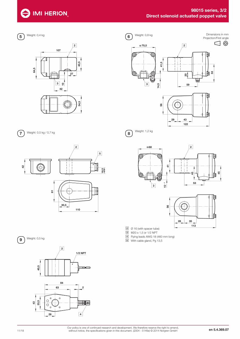
Dimensions in mm Projection/First angle
2 Ø 16 (with spacer tube) 3 M20 x 1,5 or 1/2 NPT 4 Flying leads AWG 18 (460 mm long) 5 With cable gland, Pg 13,5
Weight: 0,4 kg Weight: 0,8 kg
Weight: 0,5 kg
Weight: 0,5 kg / 0,7 kg Weight: 1,2 kg

10 12 13
15 16
T
17
T
11
14
98015 series, 3/2 Direct solenoid actuated poppet valve
Our policy is one of continued research and development. We therefore reserve the right to amend, without notice, the specifications given in this document. (2004 - 5146e) © 2014 Norgren GmbHen 5.4.369.08
11/18
Circuit diagrams
Cable gland
0588925 only
C
A
B D
C
A
B D
Dimensions in mm Projection/First angle
AccessoriesExhaust guard
Model: M/S2, M/S4, C/S2 & C/S4 Model: 0613422 & 0613423
B Suitable for G C Ø D Weight (g) Model
1/4” G1/4, 1/4 NPT 10 26,5 21 5 0613422
1/2” G1/2, 1/2 NPT 12 33,5 29 11 0613423
ø D
C
G
B
C
G
ø D B
B G C Ø D Weight (g) Model
G1/4 7 35,5 15,5 2,9 M/S2
1/4 NPT 7 35,5 15,5 2,9 C/S2
G1/2 12 67 23 11,5 M/S4
1/2 NPT 12 67 23 11,5 C/S4
Silencer
A B C ø D Model
M20 x 1,5 10 40 7,0 ... 12,0 24 0589735
M20 x 1,5 10 43 10,0 ... 14,0 27 0589736
M20 x 1,5 10 40 6,0 ... 12,0 24 0589737
M20 x 1,5 10 39,5 5,0 ... 10,0 24 0589739
M20 x 1,5 9 36 5,0 ... 8,0 22 0588819
M20 x 1,5 12 37 9,0 … 14,0 30 0588851
1/2 NPT 15 58 7,5 ... 11,9 24 0588925
M20 x 1,5 6,5 27,5 9,0 ... 13,0 22 0589385
M20 x 1,5 16 40 7,0 … 12,0 24 0589395
M20 x 1,5 16 41 10,0 … 14,0 24 0589387

Our policy is one of continued research and development. We therefore reserve the right to amend, without notice, the specifications given in this document. (2004 - 5146e) © 2014 Norgren GmbH
98015 series, 3/2 Direct solenoid actuated poppet valve
en 5.4.369.0911/18
Dimensions in mm Projection/First angle
NAMUR hole pattern (actuator side)
M5
32
2
24
3 (4)
2
1
1 Coding stud threaded 2 8 mm deep
Single connection plateModel: 0612790
19
12 12
34,5
104
2127ø 9
ø 14,5
25,5 M5 (4x)
41
25,5
1616
11,5
19
1012
29
35
3019
60
ø 5,5
ø 9,5
G1/4
19
G1/
4
19
3 (4)
2
2 3 (4)
NAMUR quick exhaust module for a better kv-value by exhaust see data sheet 5.4.820
NAMUR interlinking plates in redundancy design for »safety exhausting« and »safety ventilating« see data sheet 5.4.830
C
GB
Silencer (Stainless steel and brass)
B C G Weight (g) Model
G1/4 33 8 17 18 T40C2800
1/4 NPT 35 8 9/16 18 MS002A
G1/4 36 8 16 23 0014613
1/4 NPT 36 8 16 67 0613678
G1/2 56 12 27 63 T40C4800
1/2 NPT 48 12 7/8 63 MS004A
G1/2 49 12 24 81 0014813
1/2 NPT 49 12 24 235 0613679
Mounting plateModel: 0613453 (90°)
3
21
12
3 2
1
12
1224
12
9
32
16
20
16
43,555
55
32
2024
12
M5
7

3
21
3
24
G1/8 8
27.5
32
551.3
~ 33
7.5
30
3
21
M5
12
2442
80
ø 5
.5
G1/
4 43
M5
G3/
8
ø 1
5.5
ø 1
9.5
M5
1 2
3
4
5
98015 series, 3/2 Direct solenoid actuated poppet valve
Our policy is one of continued research and development. We therefore reserve the right to amend, without notice, the specifications given in this document. (2004 - 5146e) © 2014 Norgren GmbHen 5.4.369.10
11/18
NAMUR slot Yoke Throttle control plateModel: 0612791 Model: 0540593 Model: 4040239
205
12
65
2x
50
M5
41
2 2
1 1
32
15,5
45
12
12
19,5
76 4
M 5
87,
5
25
15,5
15,5
41
60°
11
51
9,5
512
5,5
5,5
Dimensions in mm Projection/First angle
WarningThese products are intended for use in industrial compressed air and fluid systems only. Do not use these products where pressures and temperatures can exceed those listed under »Technical features/data«.Before using these products with fluids other than those specified, for non-industrial applications, life-support systems, or other applications not within published specifications, consult IMI Precision Engineering, Norgren GmbH.Through misuse, age, or malfunction, components used in fluid power systems can fail in various modes.The system designer is warned to consider the failure modes of all component parts used in fluid power systems and to provide adequate safeguards to prevent personal injury or damage to equipment in the
event of such failure.System designers must provide a warning to end users in the system instructional manual if protection against a failure mode cannot be adequately provided.System designers and end users are cautioned to review specificwarnings found in instruction sheets packed and shipped withthese products.
Functional safety (SIL):Suitable for certain applications can only be evaluated through examination of each safety-related overall system with regard to the requirements of IEC 61508/61511.
Diese Produkte sind ausschließlich in Druckluft- und Fluidsystemen zu verwenden. Sie sind dort einzusetzen, wo die unter »Technische Merk-male/-Daten« aufgeführten Werte nicht überschritten werden. Berücksichtigen Sie bitte die entsprechende Katalogseite. Vor dem Einsatz der Produkte bei nicht industriellen Anwendungen, in lebenser-haltenden- oder anderen Systemen, die nicht in den veröffentlichten Anleitungsunterlagen enthalten sind, wenden Sie sich bitte direkt an IMI Precision Engineering, Norgren GmbH. Durch Missbrauch, Verschleiß oder Störungen können in Fluidsystemen verwendete Komponenten auf verschiedene Arten versagen.Systemauslegern wird dringend empfohlen, die Störungsarten aller in Hydrauliksystemen verwendeten Komponententeile zu berück-
sichtigen und ausreichende Sicherheitsvorkehrungen zu treffen, um Verletzungen von Personen sowie Beschädigungen der Geräte im Falle einer solchen Störung zu verhindern. Systemausleger sind verpflichtet, Sicherheitshinweise für den End-benutzer im Betriebshandbuch zu vermerken, wenn der Störungs-schutz nicht ausreichend gewährleistet ist.
Funktionale Sicherheit (SIL):Die Eignung für konkrete Einsatzfälle kann nur durch die Betrachtung des jeweiligen sicherheitsgerichteten Gesamtsystems im Hinblick auf die Anforderungen der IEC 61508/61511 bewertet werden.
Quick exhaust module Model: 4050218
1 Flanged surface NAMUR or externally mounted valve2 Flanged surface NAMUR actuator3 Push-in threaded piece after plate mounting
(to secure correct position)4 8 mm deep5 Flow regulator assembly