Embed Size (px)
Citation preview

Paper No.
496 The NACE International Annual Conference and Exposition
HOW TO PREVENT GALVANIC CORROSION IN SEAWATER PIPING SYSTEMS
Per O1av Gartland, Roy Johnsen and Stein ValenCorrOccan as
Tcglg&dcnN–7034 Trondhcim, Norway
Trend Rogne and John M. DrugliSINTEF Corrosion Center
N–7034 Trondhcim, Norway
ABSTIRACT
Galvanic corrosion on the least nobcl material can be a serious problcm when two dissimilarmaterials are coupled together in a seawater piping systcm. Typical examples of such couples arecarbon steel or copper nickel alloys coupled to s{ainlcss steel or titanium. Mathcmatieal modelingand field experience show that the use of an ir~sulating spool piece may efficiently reduce thegalvanic corrosion when the attack has the character of general corrosion, but less efficiently whenthe attack is more localized. In the latter case the use of internal cathodic protection is a moreeffective protection against galvanic corrosion than the spool piece.
INTRODIJCTION
Carbon steel, copper nickel alloys, stainless steels and titanium alloys are all being used in seawaterpiping systems. When the conditions arc not too severe the last two groups of materials may berather immune to corrosion, while carbon steel and the copper nickel alloys corrode at a low andpredictable rate. For several reasons, however, onc may have combinations of materials in the
Copyright01996 by NACE International.Requestsforpermissionto Publishthisnlanuscriptinanyform,inpartor inwholemustbe made in writing to NACEInternational, Conferences Division. P.O. Box 218340, Houston, Tex:s 77218-8340. The material presented and the views expressed in thispaper are solely those of the author(s) and are not necessarily endors:d by the Association. Printed in the U.S.A.

seawater system, with the result that galvanic effects lead to large and unpredictable corrosion onthe least noble m,atcrial. A typical example is old ccmcnt lined carbon steel piping partly replacedby titanium or stainless steel. Failures in the ccmcnt lining makes the carbon steel vulnerable to selfcorrosion but also to a more unpredictable galv~ nic corrosion near the coupling. Another typicalcombination is high alloyed stainless steel, e.g. 6M0 SS, joined with copper nickel piping or pipingcomponents. In this case the copper nickel material may suffer from serious galvanic attack nearthe junction.
In order to eliminate or reduce such galvanic attacks various solutions have been proposed. Twosolutions which have been tried in practice are the use of isolating flanges and insulated spoolpieces. The idea of the isolating flange is to isolat~ electrically the two dissimilar materials, therebyeliminating completely the galvanic effect. In practice, it has tumcd out that electrical isolation isalmost always ruined by electrical paths between the pipe parts through supports, pumps, etc.
The insulated spc~ol piece principle is based on the use of a relatively short pipe section separatingthe galvanic couple. The purpose of the spool piece is not necessarily to provide electrical isolation,but to provide a voltage drop due to the increased electrical resistance of the seawater in the spoolpiece. The spool piccc is typically made of a non-metallic material (GRP) or a metal with a thickcoating on the inside. If the spool piece is made of an uncoated metal, electrical isolation flangesarc required at both ends.
Galvanic corrosion is a phenomena that cannot t c studied quantitatively correct in the laboratoryunless the laboratory set–up has dimensions simil;i:r to that of the field installations. The cost aspecthas largely prccludcd such laboratory studies with rclcvancc for typical seawater piping systems onoffshore platforms in the North Sea, where the diameter of the pipes are frequcntl y above 25 cm(10”). A lCSS costly alternative for such studies .~as become the usc of appropriate mathematicalmodeling. With such a tool it has become possible to study quantitatively the galvanic corrosionattacks to be expected in pipes of various dimem ions.
In this paper mathematical modeling is applied in particular to evaluate the effect of spool piecesof various lengths when the attack on the “anodic” pipe section is uniform or is a more localizedtype of attack. These results, together with analysk of field experience, are used to come up withconclusions as to under which conditions spool pieces of a practical length can be applied toefficiently reduce galvanic attacks or if other mc:ms have to bc applied.
THE MATHEMATICAL BACKGROUND) OF THE “GALVKORR” COMPUTERMODELING PROGRAM
Modelling galvanic corrosion is basically a mode lling of the potentialThe potential in the clcctrolytc, U, has to obey tic Laplacc equation.
Pu=o
variation in the electrolyte.
(1)
In order to solve the Laplace equation one has to specify the geometry of the boundary and theboundary conditions, i.e. the current density - potential relationships at the boundary.
49(3/2

For a pipe geometry the geometry can be assumed to be strictly one-dimensional, i.e. we considerthe potential variation only in the direction along the pipe axis. The nonlinear nature of theboundary conditions prohibits an analytical soluticn in the general case, and numerical discretizationis used. Here wc have used the Finite Differenc:c Method (FDM), which leads to the followingsimple set of equations:
where Uj isneighboring
wj-l Uj q...l—— - + —.- = -$’J\J_l Rj,i_l•+RjJ+l RjJ+l
the potential at tubular element j, and R jj , ~ the electric resistance betweenelcm,ents j and j+l. I; is the current flowing across the pipe surface at element j.
(2)
the
These equations can also be established directly from the physical picture of the pipe as a chain ofresistors, as depicted in figure 1. The equations above are established by the requirement that thesum of the currents entering a particular element must be zero.
If the current entering the pipe element across the boundary, \’, had been a constant, the solutionof the set of equations had been straightforward using standard solution algorithms based on theGaussian elimination method /1/. The surface current density f is, however, typically a function ofthe potential E across the boundary. “GALVISORR” has been designed to accept realisticrelationships between i’ and E, in the sense thut experimental polarization curves are cast intopicccwise linear overvoltage curves in an E-lojj(i) diagram as shown in figure 2. For a givenpotential the net surface current density is is then given as the sum of the anodic (positive) andcathodic (negative) current densities.
While the potential U describes the potential vari ~tion in the electrolyte, the potential E describes,by definition, the potential difference bctwccn the rnctal potential and the potential in the electrolyteoutside, i.e.
E= U~Ct-U (3)
u met is here assumed to be a constant and is conveniently set equal to zero. Thus, in equation (2)U can be replaced by E, which is the quantity wc arc intcrcstcd in.
Solution of the set of equations in (2) is then obtained by choosing a suitable starting potential,linearizing the surface current term, solving with Gaussian elimination and repeating the processiteratively using the potentials from the n–th so;.ution as the starting potentials for the (n+l)-thsolution and so on.
In principle each pipe element can have its own set of overvoltage curves. In practice a number ofelements are grouped into segments to which the overvoltage curves as well as other properties areassigned. In this way it is easy to study galvanic corrosion and potential variations when two ormore materials are involved, or when the ovcwoltage curves changes along the pipe due tovariations in the fluid flow.

MODELING GALVANIC CORROSION BETWEEN STAINLESS STEEL AND CARBONSTEEL
Boundary conditions
The overvoltage curves shown in figure 2 arc used as boundary conditions for the modeling of theSS/CS couple. These curves have been construc[cd on the basis of laboratory tests and literaturedata. Further details are given in a previous paper /2/.
Modeling results
The pipe geomet:ry used is shown in figure 3. The stainless steel pipe is coupled to a carbon steelpipe of a different diameter, but not necessarily smaller as depicted in figure 3. Between the twomaterials an insulated spool piece is inserted. It had the same diameter as the carbon steel. Thestainless steel and the carbon steel pipes are assumed to bc electrically connected. The spool pieeehas an insulating layer on the inside, i.e. it allows no flow of current across its intcrfaee. The carbonsteel pipe is assumed to corrode uniformly, i.e. the whole area of the CS pipe corrodes accordingto the anodic overvoltage curve given in figure 2.
Calculations were carried out with various pipe sections of various diameters and diameter ratiosand with spool piece lengths up to 2 meters. Th~ length of the carbon steel pipe was usually 10meters and the stainless steel pipe 50 meters. A fcw calculations were run with even longer pipesections in order to ensure that this had only mirmr influcncc on the galvanic corrosion rates.
A typical potential variation along the pipe is shown in figure 4 for the 10’’/10” case.
Figure 5 shows the corrosion rate on the carbon steel at a 10’’/10” coupling. With no spool piecethe galvanic coupling enhances the attack from lCSS than 0.2 mm/year to about 1.5 mm/year.However, the effect of a spool piece is also clear. At this pipe diameter a 2.0 m spool piece rcduccsthe attack to between 0,3 and 0.4 mm/year.
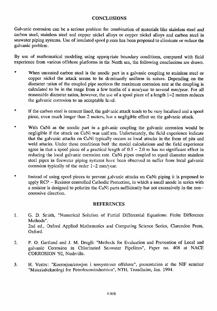
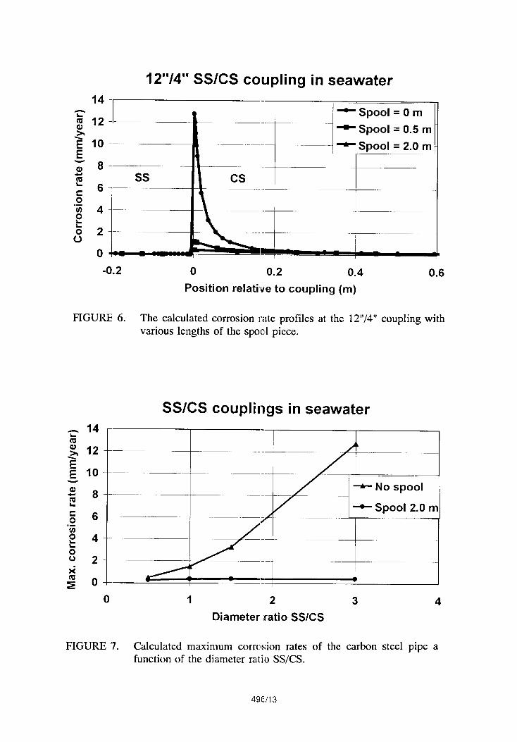
With a larger diameter ratio SS/CS the situation is more severe without a spool piece, as shown infigure 6 with a 12’’/4” diameter ratio. But also i:l this case the spool piece has a very beneficialeffect. From similar calculations with other diamc{ cr ratios it was found that the maximum corrosionrates were more strongly related to the diameter ratios than the actual diameters, for CS pipediameters in the range 4“ to 10”. Maximum corrosion rates on CS in coupling with SS with variousdiameter ratios are therefore summarized in fi,g,ure 7. Despite of the dramatic increase in themaximum corrosion rate at high diameter ratios, a 2,0 m spool piece is observed to almost eliminatethe galvanic problem.
If the carbon steel pipe is ccmcnt lined, the corrosion attack can be much more localized. Figure8 shows the result of calculations with an assumed local anode of 10 cm2 coupled to a stainless steelvalve of pump at various distances. This situation strongly contrasts that with uniform corrosion onCS in the sense that the separation, even at lengths of the order 50 – 100 meters, cannot eliminatethe galvanic problcm.
496/4

MODELING GALVANIC CORROSION BETWEEN STAINLESS STEEL AND CuNi
Boundary conditions
For the SS/CuNii couple the overvoltage curves shown in figure 9 have been used as boundaryconditions. Like the boundary conditions for the SS/CS couple these curves have been constructedfrom laboratory data and data found in the literal ure. While the seawater for the SS/CS study wasassumed to be saturated with oxygen and with up to 1 ppm chlorine, we have also included onecathodic curve with 10% oxygen and no chlorine. The latter curve is assumed to be representativeof stagnant seawater in firewater branch piping, where many SS/CuNi couplings are found.
Modeling results Case 1. Constant diameter pipe couplings.
In this section we shall focus on results with SSCuNi couplings on pipe sections with equal andconstant diameter. This simplification is made in order to highlight the difference between uniformand Ioeal attack. While uniform attack is a reasonable assumption for carbon steel in seawater, theattack on CuNi alloys ean be much more local in nature. Practical experiences with this will beshown and discussed in a later section of the paper.
Figure 10 shows the results for a 10’’/10” coupling with uniform corrosion on the CuNi pipe, i.e.the CuNi pipe is assumed to be fully activated over the whole area. It shows that the corrosion ratesare much smaller than for the em-responding SS/CS couple, as depicted in figure 5. This is due tothe fact that the corrosion potential of CuNi is much more positive than that of CS, which again hasthe effect that bath the self corrosion rate and the galvanic effect of SS beeomcs smaller.
This situation changes dramatically when local cmrosion on CuNi is assumed. Figure 11 showsthe calculated maximum corrosion attack at the coupling when the attack on the CuNi pipe isassumed to be localized to a 2 cm wide girth weld near the coupling. Depending somewhat on thediameter of the pipe the maximum corrosion rates with this local attack rises to 0.35 -0.5 mm/year.In contrast to the SS/CS couple it is also clear that a spool piece of 2.0 m length has only amarginal effect in reducing the corrosion rate. As shown in figure 11 the spool piece length has tobe of the order 10 - 15 m to reduce the maximum corrosion rate by a factor of practicalsignificance.
Modeling results. Case 2. Firewater piping systerns.
A firewater piping system may consist of a large diameter main ring pipe from which a largenumber of smaller diameter pipes branches off. The branching pipes as well as the main ring pipeare often made of 6 Mo stainless steel. The branching pipes may end at a fire-hose station madeof CuNi. This creates a galvanic couple between stainless steel and copper nickel. In order to studyproperly the galvanic corrosion at this junction ii may be necessary to include the main ring pipein the model because it has such a large cathodic capacity. For that purpose the geometric modeldepicted in figure 12 was constructed. The boundary conditions used are the same as shown infigure 9, but wit!h the specific choice that the main ring pipe is assumed to carry 100 % oxygensaturated seawater and the branching SS pipe 1070 oxygen saturated seawater. The latter beeausethe water in the branching pipe is more stagnant. [n these calculations the local attack was assumedto cover a 1 cm wide circumferential strip representing a girth weld.
4135/5

Figure 13 shows some of the results, where the maximum corrosion rate is obtained as a functionof spool piece length up to 1.5 m. As for the case shown in figure 11 the effect of the spool pieceis very weak up to 1.5 m length. The maximum corrosion rate in figure 13 is also about a factorof two larger than in figure 11, which is to be expected because of the active anode strip on theCuNi pipe is smidler by the same factor. The effact of the diameter of the branching pipe is smallcompared to that of case 1 in figure 11. 100 % o{ ygen in the branching pipe is also shown to havea negligible influence on the maximum corrosion rate.
An interesting aspect of the geometry in the firewater piping system is that the branching pipe itselfacts to limit the galvanic corrosion. This is shown in figure 14 for two diameters. In both cases themaximum corrosion rate decreases when the leng[h of the branch pipe increases. The reason is quiteevident. Since the main ring pipe represent the dominant cathodic capacity of the stainless steelcoupled to CuNi an increased separation between the main ring pipe and the CuNi pipe has to bebeneficial.
DISCUSSION
Galvanic attacks on carbon steel
In seawater the corrosion attacks on carbon steel are rather predictable because the attacks in generalare of a uniform nature. Uncoated carbon steel has therefore been used in seawater systems onplatforms at the Frigg Field, Valhall and Ekofisk, In some cases the corrosion problems have beenlarger than expected, as observed due to galvanic coupling to CuNi or stainless steel valves andpumps /3/. In these cases it has been recommended to apply spool pieces and/or isolation gaskets.The effect of using spool pieces in these cases ha$ not been documented, but extensive failures dueto galvanic coup] ings in the presence of spool pieces is not known to the authors.
Spool pieces have also been recommended for some galvanic couplings with carbon steel in theseawater piping system, the produced water systcrn and the waste water drainage on the Gullfaksplatforms. The experience from Gullfaks is concluded to be generally good /4/.
From the above, the field experience with spool pieces to prevent excessive galvanic corrosionattacks on carbon steel should be considered positive. This is in line with the results of ourcalculations depicted in the figures 4–7, that spool pieces should have a strong damping effect onthe galvanic attack on carbon steel provided the attack is of a fairly uniform nature.
If the attack is very localized the situation is quite different. If the carbon steel pipe is cement lined,as have been used e.g. in the ballast water system on the Statfjord A platform, local attacks on thecarbon steel at cracks and failures in the cement lining will occur. Under such conditions stronggalvanic effects are to be expected due to coupling to stainless steel pumps/valves. As shown infigure 8 the galvanic effect decays very slowly wil h the distance between the anode and the cathode.The undamaged cement lined carbon steel pipe here acts as a spool piece, but the effect of it israther limited even for distances of the order 50 – 100 m. The introduction of shorter dedicatedspool pieces to separate stainless steel and the cement lined carbon steel pipe would be rathermeaningless, here.

Galvanic attacks on CuNi
On CuNi alloys in seawater local attacks seem to bc more the rule than the exception, in contrastto what is the ease with carbon steel. We shall here discuss two different cases of reported failuresdue to galvanic corrosion, in which the attacks am highly localized.
The first ease is from the Oscberg platform, whine corrosion penetration was observed on CuNi
pipes galvanically eouplcd to 6M0 stainless steel piping /3/. The diameter of the pipes varied from4“ to 10” and the wall thicknesses from about 2.5 to 5.5 mm. Penetration was observed at afrequency indicating corrosion rates of the order 1-2 mm/year for all dimensions. Spool pieces werenot installed.
The results shown in figure 11 have some relevanec to the Oscbcrg observations although themaximum corrosion rates are somewhat lower in the calculations presumably due to a larger areaof attack. As shown in figure 13 a reduction of tl~e anodic area causes the galvanic corrosion rateto increase. The essence of the results in figure 11 are twofold. Firstly, it is quite clear that theattack must bc very localized to get the high pcnc~ration rates reported. Secondly, it is equally clearthat this very localized corrosion on the CuNi pipe cannot be suppressed sufficiently with the useof spool pieces of practical lengths, i.e. in the ran,gc 0.5 – 2.0 meters. This argument is valid forall the dimensions in question.
The second case is from the Draugen platform. This case rcscmblcs that of the Oscbcrg platformin the sense that ,hcavy local attacks were observed on CuNi piping coupled to 6M0 stainless steelat the fire–hose stations. A number of couplings have been inspcctcd and the observed attacks areshown for one of them in figure 15. At the Draugcn, platform spool picccs had already been installedin the form of rubber coated 6M0 pipes, and this seemed to have no appreciable effect.
This is very well in line with our calculations.The results of the calculations shown in the figures13 and 14 are relevant for the Drdugcn problcm. Figure 13 shows that a spool piece of 0.5 m, asapplied on Drau,gcn, has no practical effect in rcd ucing the galvanic attack.
Another interesting aspect of the Draugcn problc m is that the maximum corrosion rates estimatedfrom the measured depths versus exposure time varied somewhat with the length of the branch pipe.The longer the pipe the lower the corrosion rate. This is qualitatively in agreement with ourcalculations in figure 14. The quantitative agrccmcnt is also fairly good, assuming that our modeledanodic area is rcprcscntative for the true attacks in the various eases. The results are summarizedin table 1. The conclusions for the Draugcn case is that the installed 0.5 m spool piece hasessentially no effect.
Application of R.CP - Resistor controlled Cathodic Protection
A better solution than using a spool piccc to protect CuNi from galvanic corrosion would be toapply RCP –Resistor controlled Cathodic Protection . The RCP method has been developed
essentially as a means to prevent local corrosion on stainless steels in piping systems with varioustypes of saline waters, in which a critical combination of the potential and the temperature may beexccedcd /2,5,6/. With only minor modifications F:CP can also be applied to prevent galvanic attackon CuNi piping.
49?lff

The basic principle of the method is to apply catlmdic protection to a pipe systcm of stainless steelusing a resistor in series with the anode to control both the potential near the anode and the anodecurrent output. The principle is shown schcmaticall y in figure 16.
The method is further based on the observation that the protection potential for prevention of localcorrosion on stainless steel is much more positiv,~ than the typical potentials of sacrificial anodes.The voltage drop over the resistor is therefore designed to obtain sufficiently but not excessivelynegative polarization of the stainless steel. The resistor control thus keeps the stainless steel in aprotective potential range, where the current rcquircmcnts are very small in many salineenvironments, like in chlorinated seawater, in prcduccd water from the oil and gas production andin natural seawa{cr above about 30”C. Due to the very low current requirements in the relevantpotential range, al single anode can protect large Icngths of the pipe systems at a very low anodeconsumption rate.
When applied to ]protect CuNi from galvanic corrc~sion due to nearby stainless steel piping, the RCPanodes should preferably be installed close to the CuNi piping. The idea is that the anode shouldpolarize the CuNi sufficiently in the negative direction, e.g. to a lCVC1near -200 mV SCE at whichno excessive corrosion can take place according to the anodic polarization curve of figure 9. Inorder to demonstrate the effect of RCP wc have run a calculation for the fircwatcr geometry infigure 12, where a small resistor controlled sacrificial aluminium anode is installed in the pipesystcm at origo, i.e. at the coupling bctwccn the branch pipe and the spool piccc. In this calculationthe branch pipe diameter was 3“, the branch pipe length 5 m and the spool piece length 0.5 m. TheCuNi pipe was 1,0 m long of which a 1 cm section was assumed to bc active while the rest of theCuNi pipe was assumed to be in the passive state. The potential profile near the active CuNi isshown in figure 17, both with and without the anode. The polarization provided by the anode hasthe effect that the corrosion rate on the active CuNi part is rcduccd to an acceptable lCVC1,as shownin table 2. Table ‘2also shows that the sacrificial anode consumption is cxtrcmcly low, of the order10 grams/year. A. very small anode is thcrcforc required to protect the CuNi pipe for many yearswithout rcplaccmcnt.
If anode attachment C1OSCto CuNi is not feasible one may achieve good protection also with theanodes at some distance, but the anode consumption rate will then be larger. Even with no anodesin the branch piping but a sufficient number in tkc main ring pipe there will bc a strong reductionof the galvanic corrosion of CuNi in the branch pipe. This is duc to the anodes “consuming” thelarge cathodic capacity of the main ring pipe.
For a given piping systcm the RCP method can bc optimized in terms of a minimum number ofanodes, a minimum anode consumption and a safe: potential Icvcl utilizing the knowledge about thepolarization propmtics of the materials involved and a calculation tcchniquc as demonstrated in thepresent paper.
CONCLIJSIONS
Galvanic corrosion can be a serious problem for combination of materials like stainless steel andcarbon steel, stainless steel and copper nickel alloys or copper nickel alloys and carbon steel inseawater piping systems. Use of insulated spool p:.cccs has been proposed to eliminate or reduce thegalvanic problem.
By use of mathematical modeling using appropriate boundary conditions, compared with fieldexperience from various offshore platforms in the North sea, the following conclusions are drawn.
*
*
*
*
1.
2.
3,
When uncoated carbon steel is the anodic: part in a galvanic coupling to stainless steel orcopper nickel the attack seems to be dominantly uniform in nature. Depending on thediameter ratios of the coupled pipe sections the maximum corrosion rate at the coupling iscalculated to be in the range from a few tenths of a mm/year to several mm/year. For allreasonable diameter ratios, however, the use of a spool piece of a length 1-2 meters reducesthe galvanic corrosion to an acceptable le ~el.
If the carbon steel is cement lined, the gal~r;mic attack tends to be very localized and a spoolpiece, even much longer than 2 meters, has a negligible effect on the galvanic attack.
With CuNi as the anodic part in a gal~ anic coupling the galvanic corrosion would benegligible if the attack on CuNi was unif~rm. Unfortunately, the field experience indicatethat the galvanic attacks on CuNi typically occurs as local attacks in the form of pits andweld attacks. Under these conditions botl the model calculations and the field experienceagree in that a spool piece of a practical length of 0.5 – 2.0 m has no significant effect inreducing the local galvanic corrosion rate. CuNi pipes coupled to equal diameter stainlesssteel pipes in fircwatcr piping systems h;rve been observed to suffer from local galvaniccorrosion typically of the order 1–2 mm/jcar.
Instead of using spool picccs to prevent g,alvanic attacks on CuNi piping it is proposed toapply RCP – Resistor controlled Cathodic Protection, in which a small anode in series witha resistor is designed to polarize the CuNi parts sufficiently but not cxccssivcly in the non–corrosive direction.
REFERENCES
G. D. Smith, “Numerical Solution of Partial Differential Equations: Finite DifferenceMethods”:,2nd cd., [Oxford Applied Mathematics and Computing Science Series, Clarcndon Press,Oxford.
P. O. Gartland and J. M. Drugli: “Methods for Evaluation and Prevention of Local andgalvanic Corrosion in Chlorinated Sexwatcr Pipelines”, Paper no. 408 at NACECORROS1ON ’92, Nashville.
H. Vcstre: “Korrosjon/crosjon i rorsystemcr offshore”, presentation at the NIF seminar“Matcrialtcknologi for Pctrolcumsindustricn”, NTH, Trondhcim, Jan. 1994.
43619

4. Private cc~mmunication with Ivar Nyb@ Statoil, Bergen.
5. R. Johnsen, P. O. Gartland, S. Valen and J. M. Drugli: “The Resistor Controlled CathodicProtection Method for Prevention of Local Corrosion on Stainless Steels in Saline WaterPiping Systems”, paper at the 7th Middle East Corrosion conference, Bahrain, February,1996.
6. R. Johnsen, P. O. Gartland, S. Valen and J. M. Drugli: “Internal cathodic Protection ofSeawater Piping System by the use of the RCP Method”, paper no. 559 at NACECORROSION ’96, Denver, Colorado.
TABLE 1.
VARIATION OF OBSERVED AND CALCULATED MAXIMUM CORROSION RATESWITH THE LENGTH CF THE BRANCH PIPE.
Branch pipe length Observed maximum(m) corrosion rates (mm/year)
.—
1.7 ca. 1.5 – 2.0
calculated maximumcorrosion rates (mm/year).From figure 14, 3 “ pipe
ca. 1.1
ea. 0.9
ca. 0.55
TABI.E 2.
CALCULATED POTENTIALS AND CORROSION RATES FOR THE FIREWATERBRANCH SS/CUNI COUPLING WITH AN]] WITHOUT A RESISTOR CONTROLLED
SACRIFICIAL ANODE l\ EAR THE COUPLING.
7m:-
‘Ew; :,,2 ;,.5
4!36/1o

-4—T—4——4——T——T
ELEMENT NO.
FIGURE 1. Illustration 01 the pipe fluid as a chain of finite resistors in thefinite difference approximation.
Overvoltage curves for SS and CS in seawater
600
400- Anodic SS- Anodic CS
200- - Cathodic CSo ~ Cathodic SS
-200-
-400-
-600---——--
-800-
1.00E-03 I.00E-01 I.00E+O1 1.00E+03 1.00E+05
Current density (mA/m2)
FIGURE 2. Overvoltage cuncs for stainless steel (SS) and carbon steel (CS) inchlorinated seawater.
L-J=d--===I
—zI
FIGURE 3. Schematics of a <:ouplingbetween stainless steel and carbon steelor copper nickel, where the coupled pipes have different diameters.The spool pieee ISassumed to have thediameter of the smallestpipe.
496/1 1

10“/1 O“ SS/CS coupling in seawater
400
g 200(#l ----- ~ ‘---d 0:g -200
~-400- —:
- :1 -~ . pic
~ -600 -——-—
-800 -- I
-50 -40 -30 -20 -10 0 10
Position relative to coupling (m)
FIGURE 4. The calculated potential profile along a 10’’/10” coupling betweenstainless steel and carbon steel.
10’’/10” SS/CS coupling in seawater
1.6a SpOOl = O mcm 1.4 .t SpOOl = 0.5 m
g 1.2- - spooi = 2.0 mg 1. -–
~ 0.8 --—
~ 0.6 --—.-3 0.4
0 ●.
-0.2 0 0.2 0.4 0.6 0.8 1Position relative to coupling (m)
FIGURE 5. The calculated corrosion rate profiles at the 10’’/10” SS/CScoupling with various lengths of the spool piece.
496/12
12“/4” SS/CS coupling in seawater
-“’r-~ Spool = O m—- spool = 0.5 m
—-- - spool = 2.0 m -
SsII Cs
—
>
.—
.
—
m ~ “;_ . -
-0.2 0 0.2 0.4 0.6
Position relative to coupling (m)
FIGURE 6. The calculated corrosion rate profiles at the 12’’/4” coupling withvarious lengths of the spool piece.
SS/CS couplings in seawater
L“(/:“:1-++-. -. —+No SPOOI i—
~ SpOOl 2.0 m
—-——— –-—
.—
0 1 2 3 4
Diameter ratio SS/CS
FIGURE 7. Calculated maximum corrcsion rates of the carbon steel pipe afunction of the diameter ratio SS/CS.
496/13

12
10
8
6
4
2
0
SS/cementlinedl CS in seawater
r\mIz=-- -- ‘-- ---J---I I I
l-- I 11 i
0 20 40 60 80 100 120 140 160Separation between anode and cathode (m)
FIGURE 8 Calculated galvanic corroson rates as a function of the distancebetween a 10 cm2 local ancdc on a 20 “ cement lined carbon steelpipe coupled to a 1 m2 stai~lcss steel valve/pump.
Overvoltage curves for CuNi and SS in firewater
600
400
200
0
-200
-400
-600
-800
-1000
I ,- -,
‘---”--”1~“..-y --j=----,I
~ Anodic SS
~ Anodic CuNi
~ Cathodic, CuNi,Ss, 100!40 ox.
e Cathodic, CuNi,Ss, 10v, ox.
1.00E-03 1.00E-01 I.00E+OI 1.00E+03 1.00E+05
Current density (mAlm2)
FIGURE 9. Overvoltage curves for copper nickel and stainless steel infirewater.
49fj/14

10’’/10” SS/CuNi coupling in firewater
0.06n
—–l..__
FIGURE 10.
0 0.2 0.4 O.1~ 0.8 I l-z 1.4 1.6
Position relative to coupling (m)
The calculated corrosion rate profiles at the 10’’/10” SS/CuNicoupling with two different oxygen concentrations. Uniformcorrosion on the anode.
SS/CuNi coupling in firewater
RE-r—’- — —~
*- Uniform attack.—
‘- 2 cm weld attack. Diam.=lo’”
~- 2 cm weld attack. Diam.=4 “
“?
‘T-7-----4p++=-.-]
o
FIGURE 11.
5 10 15 20Spool piece length (m)
Calculated maximum corros:on rates of the SS/CuNi coupling withuniform corrosion and with the corrosion attack localized to a 2 cmwide weld area, as a functicm of the spool piece length.
496/1 5

ring pipe
lT’lr6t 1
spool CuNi pipe
\ +
Ao,
~ .30:+1
0.5, 0.01,2,5, 10,30 m
‘ ‘+
l,5m lm ,.-
1
FIGURE :12.
Om
Schematics of the gcome h-y used in the calculations for theSS/CuNi couplings on the fircwater branch piping.
SS/CuNi coupling in firewater branch piping.Length of branch pipe=2.O m.
G
-— —___ im.—__. . .-
+ Uniform attack. l)iam.=3°.
* 1 cm weld attack. l)iam.=3°
+ 1 cm weld attack. 13iam.=6° f~ 1 cm local attack. Diam.=3”. 100 % 02 Og ~-——-
u ~?’
0 0.5 1 1.5
Spool piece length (m)
FIGURE ’13. Calculated maximum corrosion rates of the SS/CuNi coupling inthe firewatcr branch piping, in dcpcndcnce of the branch pipelength. The length of the spool piccc is 0.5 m.

SS/CuNi coupling in firewater branch piping.
Spool piece length = 0.5 m.
~ 1.2s + Uniform attack. Diam. =3’”
$&
~ 1 cm weld attack. Diam=3°
~ 0.8- -- — -9-1 cm weld attack. Diam.=6’C~c 0.60.-2 0.4 --- --L5Q 0.2 -- .
:z o-
8I 1 q
0
FIGURE 14.
~_____
1.——_—_
5 10 15 20 25 30
Length cif branch pipe (m)
Calculated maximum corrosion rates of the SS/CuNi coupling inthe fircwatcr branch pi,ping, in dcpcndcncc of the spool picccIcngth. The Icngth of tlc branch pipe is 2.0 m.
1Bypass
Rubber Iincd spool in 6 Mo
Corroded iireas
~>~[>
“-%
r\
.-y
\f
Weld/
/’,/’
Pene ration //’
Weld corrosion
CuNi- pipe
.~”--”~ .
FIGURE 15. Observed corrosion attacks on a 3“ CuNi bend coupled to a SSbranch pipe. Length of bIanch pipe is 1.7 m, including 0.5 m spoolpiece.
496/ “7

R 1~ R 1~
L–_.FIGURE 16. Schematics of the RCP method applied to a pipe system.
SS/CuNi coupling in firewater branch piping
100
-300
~ No anodem
+ Anode at origo !
●
)
‘
1 1Ss spool I CuNi
-1 -0.8 -0.6 -0.4 -0.2 0 0.2 0.4 0.6 0.8 1
Position relative to ,SS/Spool coupling (m)
FIGURE 17. Calculated potential variaticn near the active CuNi for the galvanic
coupling in the branch pipe of the fircwater piping systcm with andwithout a sacrificial anode mounted at the SS/spool interface. Thebranch pipe is 3“ in diameter and 5 m long. The spool piece is 0.5m long and the active CUN: pipe is 1 cm long.
496/1 8


