Embed Size (px)
Citation preview
Shutdown SIS
Previous Screen
Product: TRACK LOADER
Model: 943 TRACK LOADER 31Y
Configuration: 943 TRACK LOADER / HIGH DRIVE / 31Y01334-UP (MACHINE) POWERED BY 3204 ENGINE
Disassembly and Assembly943-953 TRACK-TYPE LOADERS VEHICLE SYSTEMS
Media Number -SENR4216-00 Publication Date -01/03/1985 Date Updated -11/10/2001
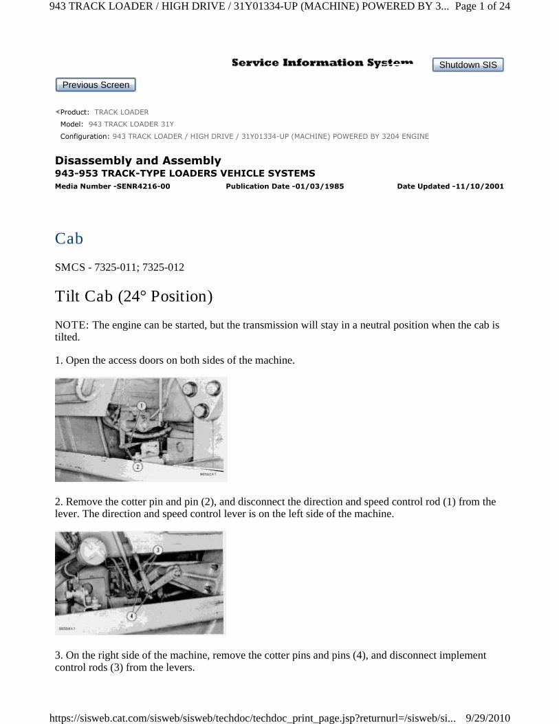
Cab
SMCS - 7325-011; 7325-012
Tilt Cab (24° Position)
NOTE: The engine can be started, but the transmission will stay in a neutral position when the cab istilted.
1. Open the access doors on both sides of the machine.
2. Remove the cotter pin and pin (2), and disconnect the direction and speed control rod (1) from thelever. The direction and speed control lever is on the left side of the machine.
3. On the right side of the machine, remove the cotter pins and pins (4), and disconnect implementcontrol rods (3) from the levers.
Page 1 of 24943 TRACK LOADER / HIGH DRIVE / 31Y01334-UP (MACHINE) POWERED BY 3...
9/29/2010https://sisweb.cat.com/sisweb/sisweb/techdoc/techdoc_print_page.jsp?returnurl=/sisweb/si...
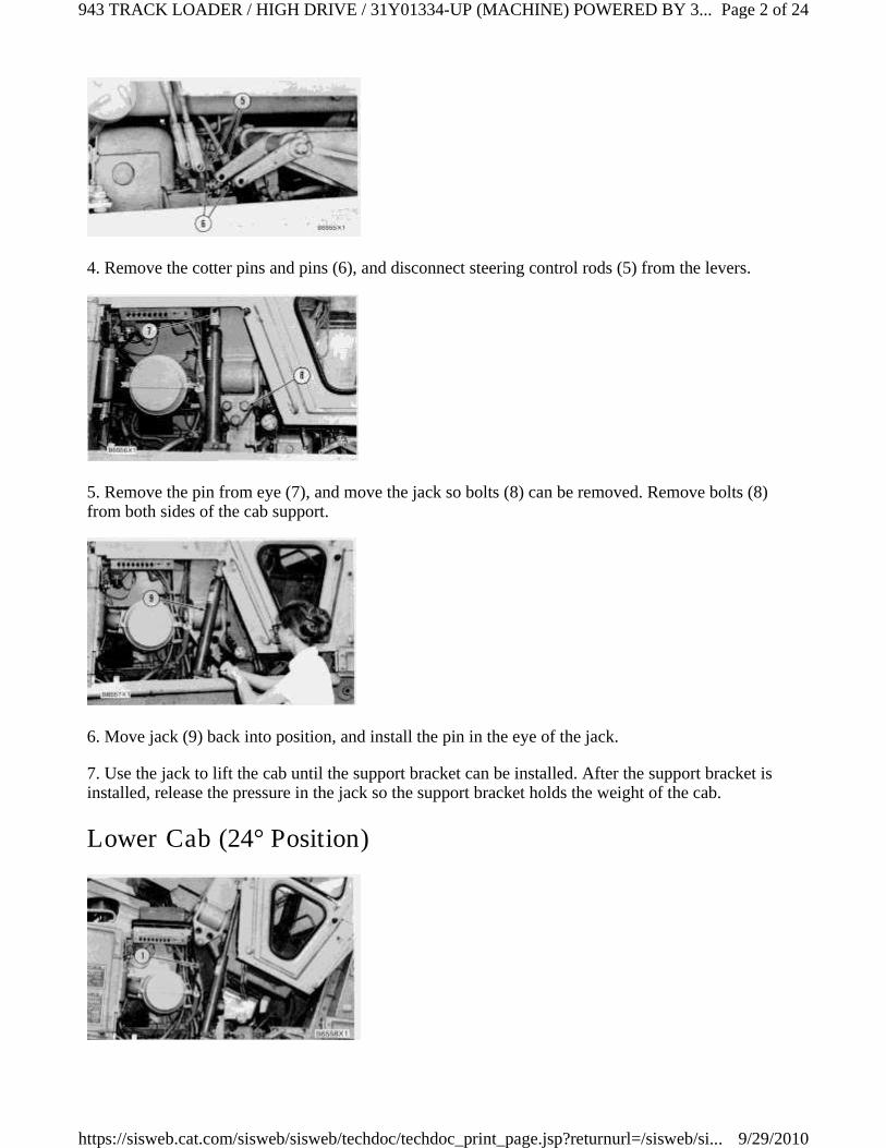
4. Remove the cotter pins and pins (6), and disconnect steering control rods (5) from the levers.
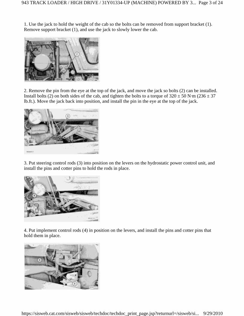
5. Remove the pin from eye (7), and move the jack so bolts (8) can be removed. Remove bolts (8)from both sides of the cab support.
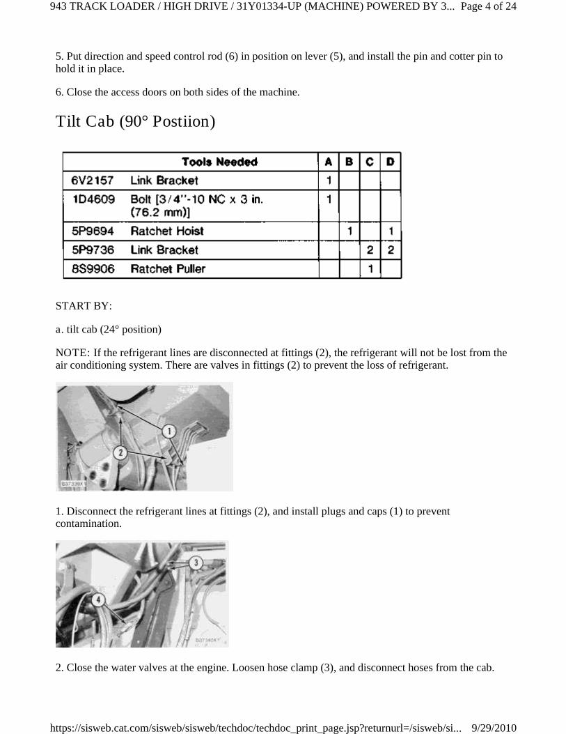
6. Move jack (9) back into position, and install the pin in the eye of the jack.
7. Use the jack to lift the cab until the support bracket can be installed. After the support bracket isinstalled, release the pressure in the jack so the support bracket holds the weight of the cab.
Lower Cab (24° Position)
Page 2 of 24943 TRACK LOADER / HIGH DRIVE / 31Y01334-UP (MACHINE) POWERED BY 3...
9/29/2010https://sisweb.cat.com/sisweb/sisweb/techdoc/techdoc_print_page.jsp?returnurl=/sisweb/si...
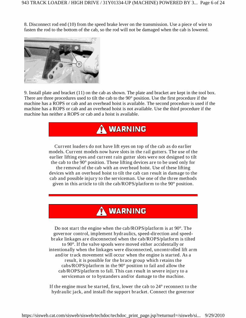
1. Use the jack to hold the weight of the cab so the bolts can be removed from support bracket (1).Remove support bracket (1), and use the jack to slowly lower the cab.
2. Remove the pin from the eye at the top of the jack, and move the jack so bolts (2) can be installed.Install bolts (2) on both sides of the cab, and tighten the bolts to a torque of 320 ± 50 N·m (236 ± 37lb.ft.). Move the jack back into position, and install the pin in the eye at the top of the jack.
3. Put steering control rods (3) into position on the levers on the hydrostatic power control unit, andinstall the pins and cotter pins to hold the rods in place.
4. Put implement control rods (4) in position on the levers, and install the pins and cotter pins thathold them in place.
Page 3 of 24943 TRACK LOADER / HIGH DRIVE / 31Y01334-UP (MACHINE) POWERED BY 3...
9/29/2010https://sisweb.cat.com/sisweb/sisweb/techdoc/techdoc_print_page.jsp?returnurl=/sisweb/si...
5. Put direction and speed control rod (6) in position on lever (5), and install the pin and cotter pin tohold it in place.
6. Close the access doors on both sides of the machine.
Tilt Cab (90° Postiion)
START BY:
a. tilt cab (24° position)
NOTE: If the refrigerant lines are disconnected at fittings (2), the refrigerant will not be lost from theair conditioning system. There are valves in fittings (2) to prevent the loss of refrigerant.
1. Disconnect the refrigerant lines at fittings (2), and install plugs and caps (1) to preventcontamination.
2. Close the water valves at the engine. Loosen hose clamp (3), and disconnect hoses from the cab.
Page 4 of 24943 TRACK LOADER / HIGH DRIVE / 31Y01334-UP (MACHINE) POWERED BY 3...
9/29/2010https://sisweb.cat.com/sisweb/sisweb/techdoc/techdoc_print_page.jsp?returnurl=/sisweb/si...

3. Put identification on, and disconnect wiring harness (4) at connectors.
4. Disconnect bracket (5), and remove hoses and wiring harness from the back of the cab.
5. Loosen the setscrews in knobs (6), and remove the knobs from the valve stems. Remove nuts (7)and lockwashers that hold hand pump (8) for track brake release to the cab.
6. Remove hand pump (8) from the bottom of the cab.
7. Remove bolts (9) that fasten the ground wire to the cab.
Page 5 of 24943 TRACK LOADER / HIGH DRIVE / 31Y01334-UP (MACHINE) POWERED BY 3...
9/29/2010https://sisweb.cat.com/sisweb/sisweb/techdoc/techdoc_print_page.jsp?returnurl=/sisweb/si...
8. Disconnect rod end (10) from the speed brake lever on the transmission. Use a piece of wire tofasten the rod to the bottom of the cab, so the rod will not be damaged when the cab is lowered.
9. Install plate and bracket (11) on the cab as shown. The plate and bracket are kept in the tool box.There are three procedures used to tilt the cab to the 90° position. Use the first procedure if themachine has a ROPS or cab and an overhead hoist is available. The second procedure is used if themachine has a ROPS or cab and an overhead hoist is not available. Use the third procedure if themachine has neither a ROPS or cab and a hoist is available.
Current loaders do not have lift eyes on top of the cab as do earliermodels. Current models now have slots in the rail gutters. The use of theearlier lifting eyes and current rain gutter slots were not designed to tiltthe cab to the 90° position. These lifting devices are to be used only for
the removal of the cab with an overhead hoist. Use of these liftingdevices with an overhead hoist to tilt the cab can result in damage to thecab and possible injury to the serviceman. Use one of the three methods
given in this article to tilt the cab/ROPS/platform to the 90° position.
Do not start the engine when the cab/ROPS/platform is at 90°. Thegovernor control, implement hydraulics, speed-direction and speed-
brake linkages are disconnected when the cab/ROPS/platform is tiltedto 90°. If the valve spools were moved either accidentally or
intentionally when the linkages were disconnected, uncontrolled lift armand/or track movement will occur when the engine is started. As a
result, it is possible for the brace group which retains thecabs/ROPS/platform in the 90° position to fail and allow the
cab/ROPS/platform to fall. This can result in severe injury to aserviceman or to bystanders and/or damage to the machine.
If the engine must be started, first, lower the cab to 24° reconnect to thehydraulic jack, and install the support bracket. Connect the governor
Page 6 of 24943 TRACK LOADER / HIGH DRIVE / 31Y01334-UP (MACHINE) POWERED BY 3...
9/29/2010https://sisweb.cat.com/sisweb/sisweb/techdoc/techdoc_print_page.jsp?returnurl=/sisweb/si...
control and speed-brake linkages, and make sure the implement valveand speed-direction spools are in their hold or centered positions before
starting the engine.
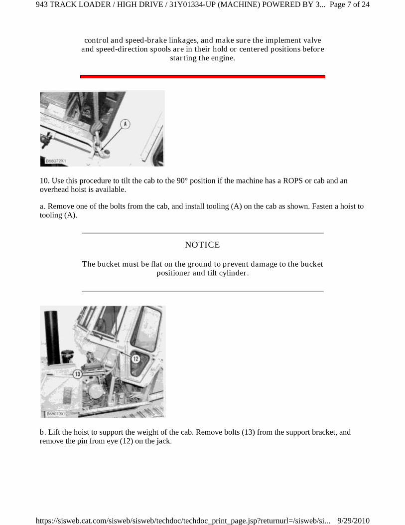
10. Use this procedure to tilt the cab to the 90° position if the machine has a ROPS or cab and anoverhead hoist is available.
a. Remove one of the bolts from the cab, and install tooling (A) on the cab as shown. Fasten a hoist totooling (A).
NOTICE
The bucket must be flat on the ground to prevent damage to the bucketpositioner and tilt cylinder.
b. Lift the hoist to support the weight of the cab. Remove bolts (13) from the support bracket, andremove the pin from eye (12) on the jack.
Page 7 of 24943 TRACK LOADER / HIGH DRIVE / 31Y01334-UP (MACHINE) POWERED BY 3...
9/29/2010https://sisweb.cat.com/sisweb/sisweb/techdoc/techdoc_print_page.jsp?returnurl=/sisweb/si...
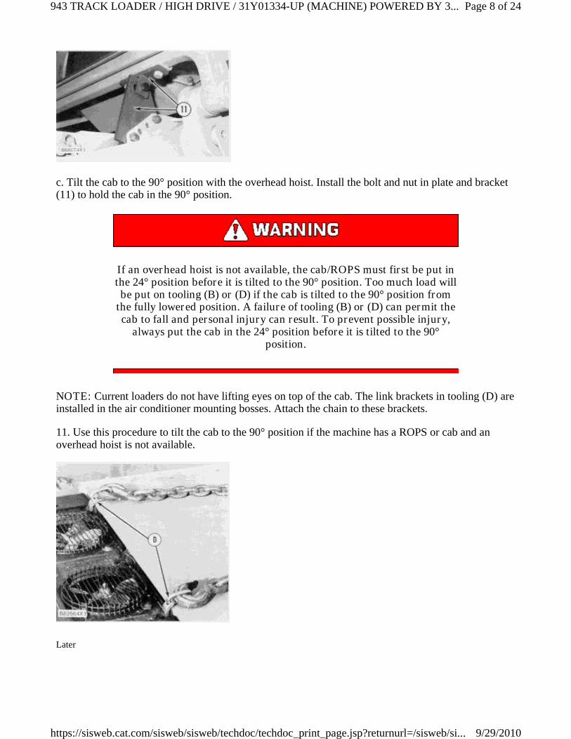
c. Tilt the cab to the 90° position with the overhead hoist. Install the bolt and nut in plate and bracket(11) to hold the cab in the 90° position.
If an overhead hoist is not available, the cab/ROPS must first be put inthe 24° position before it is tilted to the 90° position. Too much load willbe put on tooling (B) or (D) if the cab is tilted to the 90° position from
the fully lowered position. A failure of tooling (B) or (D) can permit thecab to fall and personal injury can result. To prevent possible injury,
always put the cab in the 24° position before it is tilted to the 90°position.
NOTE: Current loaders do not have lifting eyes on top of the cab. The link brackets in tooling (D) areinstalled in the air conditioner mounting bosses. Attach the chain to these brackets.
11. Use this procedure to tilt the cab to the 90° position if the machine has a ROPS or cab and anoverhead hoist is not available.
Later
Page 8 of 24943 TRACK LOADER / HIGH DRIVE / 31Y01334-UP (MACHINE) POWERED BY 3...
9/29/2010https://sisweb.cat.com/sisweb/sisweb/techdoc/techdoc_print_page.jsp?returnurl=/sisweb/si...
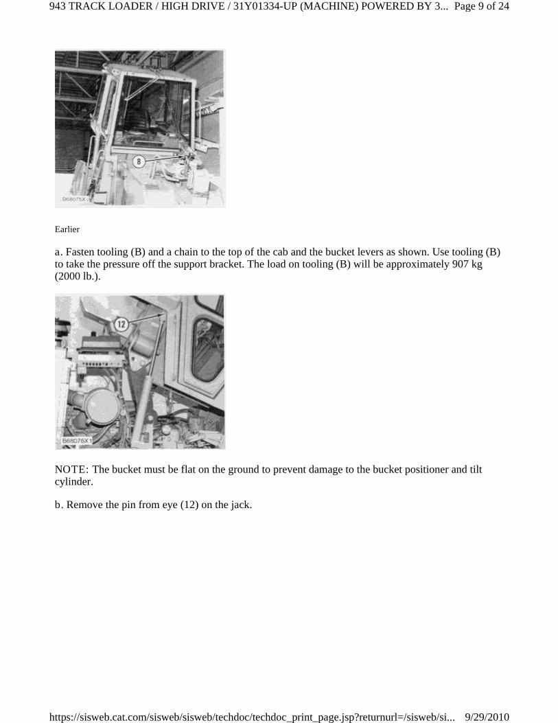
Earlier
a. Fasten tooling (B) and a chain to the top of the cab and the bucket levers as shown. Use tooling (B)to take the pressure off the support bracket. The load on tooling (B) will be approximately 907 kg(2000 lb.).
NOTE: The bucket must be flat on the ground to prevent damage to the bucket positioner and tiltcylinder.
b. Remove the pin from eye (12) on the jack.
Page 9 of 24943 TRACK LOADER / HIGH DRIVE / 31Y01334-UP (MACHINE) POWERED BY 3...
9/29/2010https://sisweb.cat.com/sisweb/sisweb/techdoc/techdoc_print_page.jsp?returnurl=/sisweb/si...
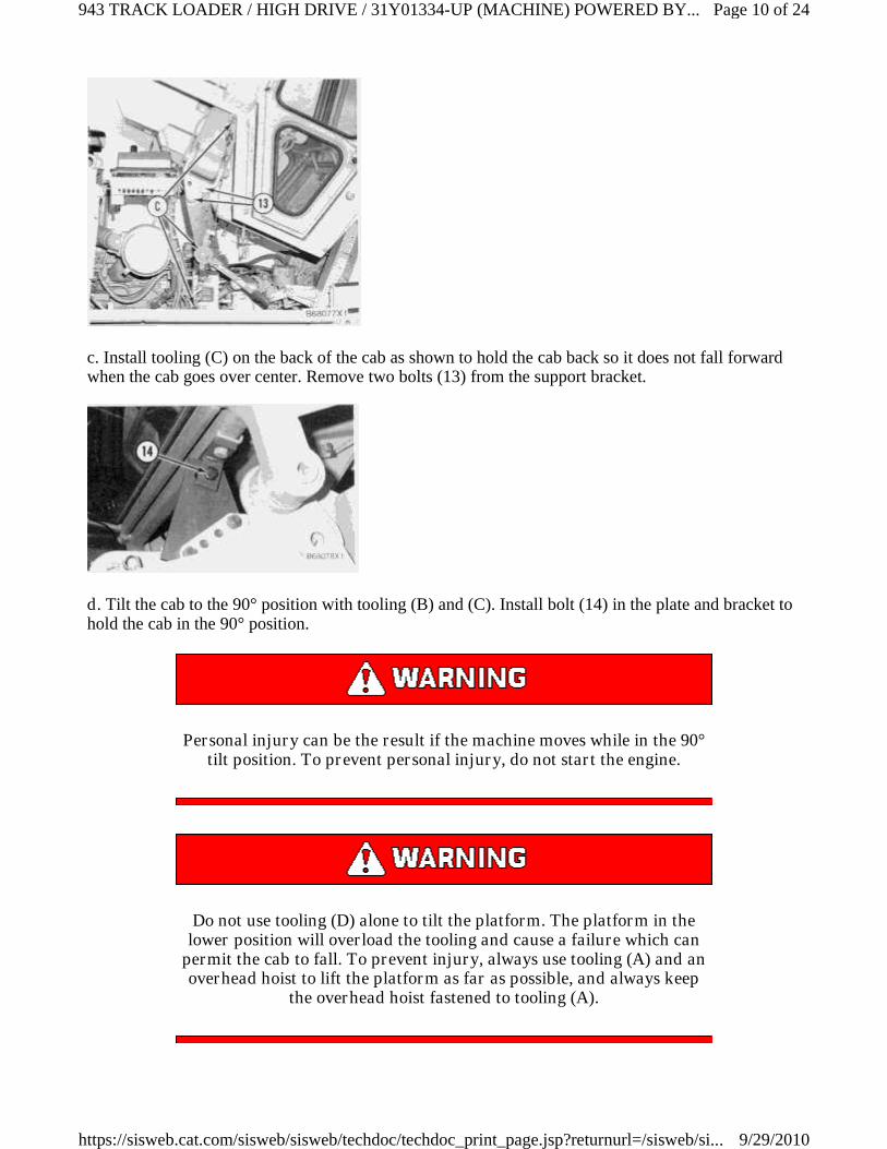
c. Install tooling (C) on the back of the cab as shown to hold the cab back so it does not fall forwardwhen the cab goes over center. Remove two bolts (13) from the support bracket.
d. Tilt the cab to the 90° position with tooling (B) and (C). Install bolt (14) in the plate and bracket tohold the cab in the 90° position.
Personal injury can be the result if the machine moves while in the 90°tilt position. To prevent personal injury, do not start the engine.
Do not use tooling (D) alone to tilt the platform. The platform in thelower position will overload the tooling and cause a failure which can
permit the cab to fall. To prevent injury, always use tooling (A) and anoverhead hoist to lift the platform as far as possible, and always keep
the overhead hoist fastened to tooling (A).
Page 10 of 24943 TRACK LOADER / HIGH DRIVE / 31Y01334-UP (MACHINE) POWERED BY...
9/29/2010https://sisweb.cat.com/sisweb/sisweb/techdoc/techdoc_print_page.jsp?returnurl=/sisweb/si...
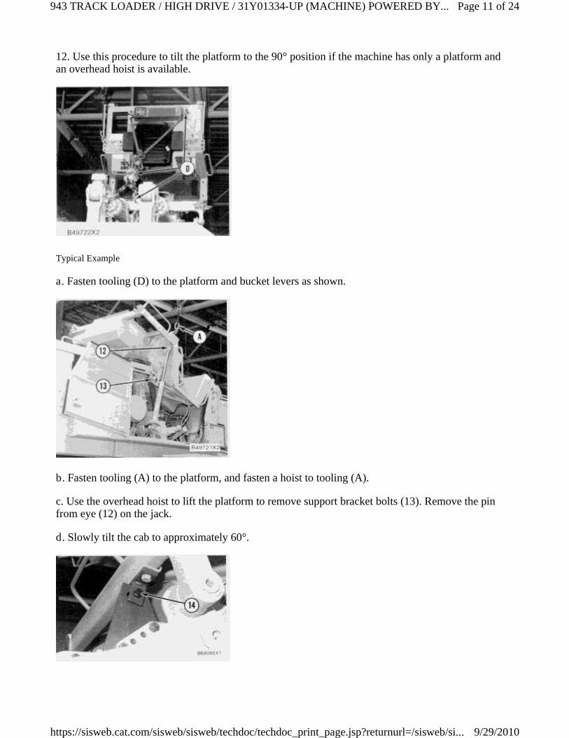
12. Use this procedure to tilt the platform to the 90° position if the machine has only a platform andan overhead hoist is available.
Typical Example
a. Fasten tooling (D) to the platform and bucket levers as shown.
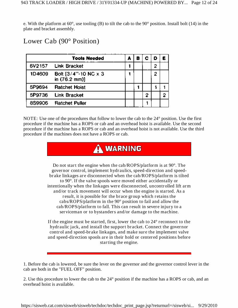
b. Fasten tooling (A) to the platform, and fasten a hoist to tooling (A).
c. Use the overhead hoist to lift the platform to remove support bracket bolts (13). Remove the pinfrom eye (12) on the jack.
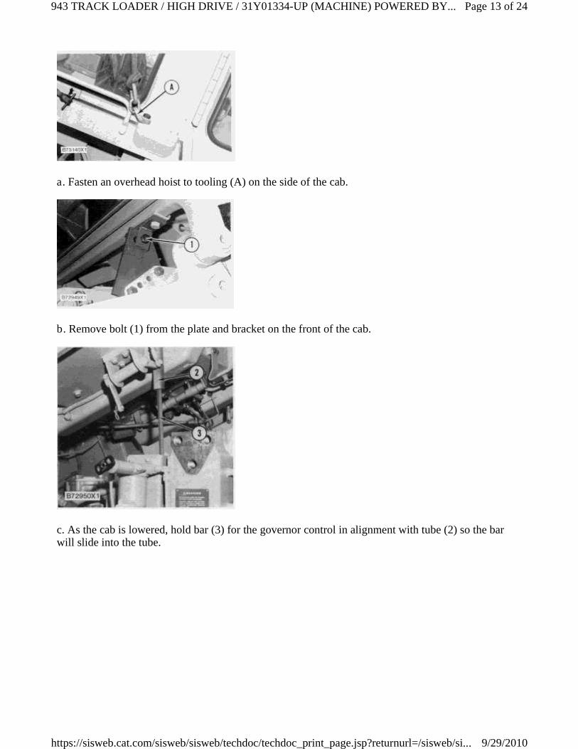
d. Slowly tilt the cab to approximately 60°.
Page 11 of 24943 TRACK LOADER / HIGH DRIVE / 31Y01334-UP (MACHINE) POWERED BY...
9/29/2010https://sisweb.cat.com/sisweb/sisweb/techdoc/techdoc_print_page.jsp?returnurl=/sisweb/si...
e. With the platform at 60°, use tooling (B) to tilt the cab to the 90° position. Install bolt (14) in theplate and bracket assembly.
Lower Cab (90° Position)
NOTE: Use one of the procedures that follow to lower the cab to the 24° position. Use the firstprocedure if the machine has a ROPS or cab and an overhead hoist is available. Use the secondprocedure if the machine has a ROPS or cab and an overhead hoist is not available. Use the thirdprocedure if the machines does not have a ROPS or cab.
Do not start the engine when the cab/ROPS/platform is at 90°. Thegovernor control, implement hydraulics, speed-direction and speed-
brake linkages are disconnected when the cab/ROPS/platform is tiltedto 90°. If the valve spools were moved either accidentally or
intentionally when the linkages were disconnected, uncontrolled lift armand/or track movement will occur when the engine is started. As a
result, it is possible for the brace group which retains thecabs/ROPS/platform in the 90° position to fail and allow the
cab/ROPS/platform to fall. This can result in severe injury to aserviceman or to bystanders and/or damage to the machine.
If the engine must be started, first, lower the cab to 24° reconnect to thehydraulic jack, and install the support bracket. Connect the governorcontrol and speed-brake linkages, and make sure the implement valve
and speed-direction spools are in their hold or centered positions beforestarting the engine.
1. Before the cab is lowered, be sure the lever on the governor and the governor control lever in thecab are both in the "FUEL OFF" position.
2. Use this procedure to lower the cab to the 24° position if the machine has a ROPS or cab, and anoverhead hoist is available.
Page 12 of 24943 TRACK LOADER / HIGH DRIVE / 31Y01334-UP (MACHINE) POWERED BY...
9/29/2010https://sisweb.cat.com/sisweb/sisweb/techdoc/techdoc_print_page.jsp?returnurl=/sisweb/si...
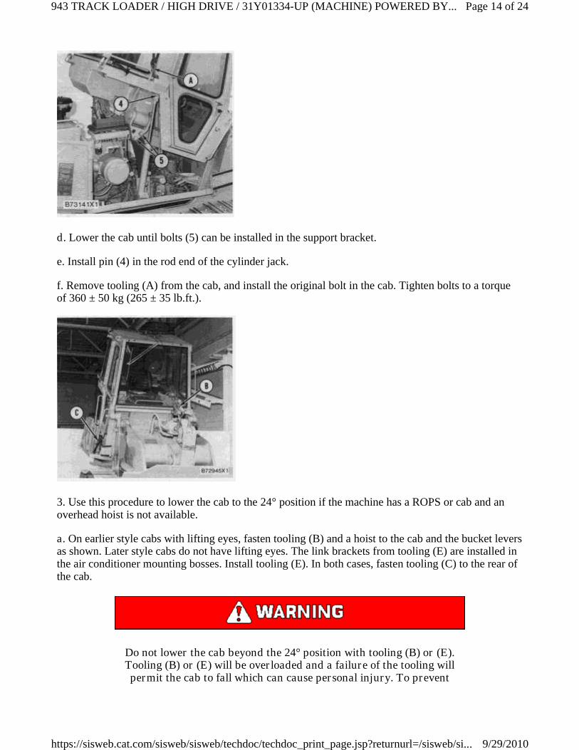
a. Fasten an overhead hoist to tooling (A) on the side of the cab.
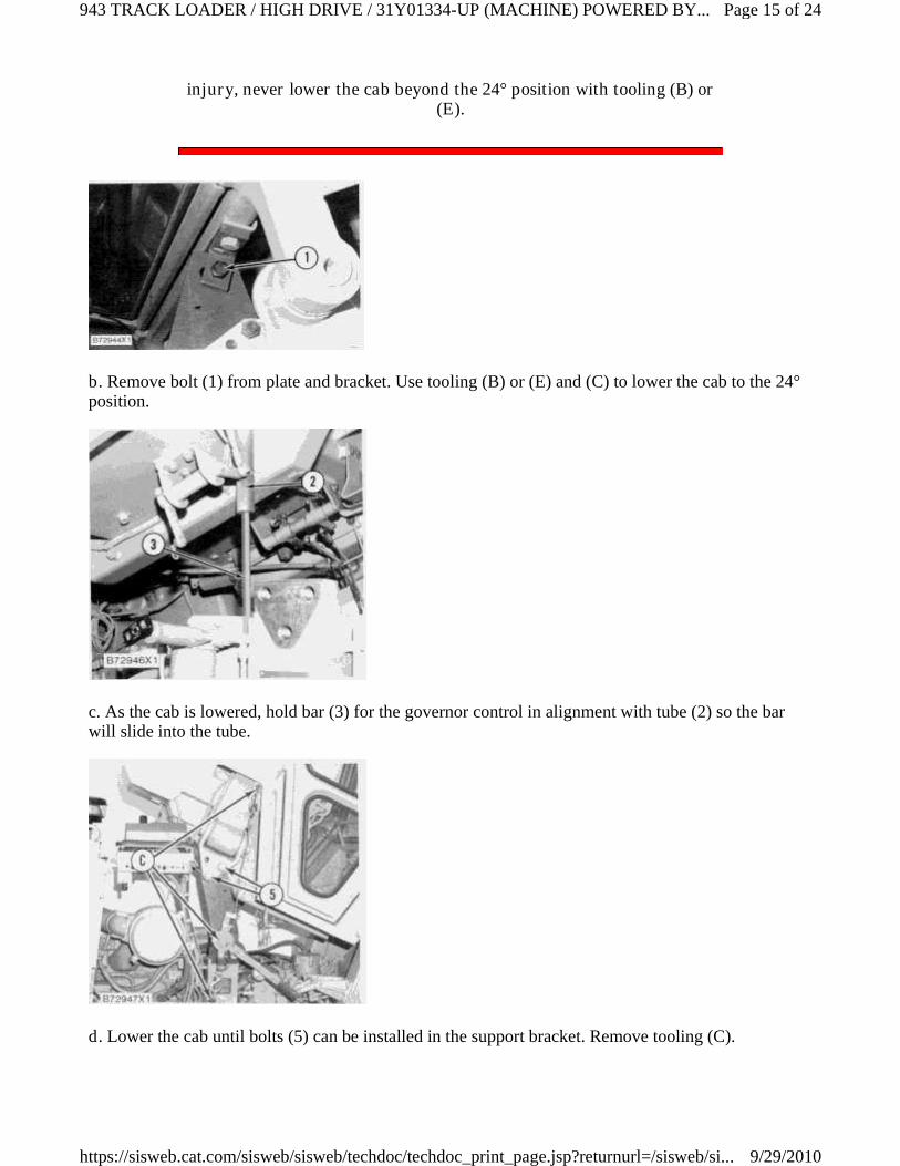
b. Remove bolt (1) from the plate and bracket on the front of the cab.
c. As the cab is lowered, hold bar (3) for the governor control in alignment with tube (2) so the barwill slide into the tube.
Page 13 of 24943 TRACK LOADER / HIGH DRIVE / 31Y01334-UP (MACHINE) POWERED BY...
9/29/2010https://sisweb.cat.com/sisweb/sisweb/techdoc/techdoc_print_page.jsp?returnurl=/sisweb/si...
d. Lower the cab until bolts (5) can be installed in the support bracket.
e. Install pin (4) in the rod end of the cylinder jack.
f. Remove tooling (A) from the cab, and install the original bolt in the cab. Tighten bolts to a torqueof 360 ± 50 kg (265 ± 35 lb.ft.).
3. Use this procedure to lower the cab to the 24° position if the machine has a ROPS or cab and anoverhead hoist is not available.
a. On earlier style cabs with lifting eyes, fasten tooling (B) and a hoist to the cab and the bucket leversas shown. Later style cabs do not have lifting eyes. The link brackets from tooling (E) are installed inthe air conditioner mounting bosses. Install tooling (E). In both cases, fasten tooling (C) to the rear ofthe cab.
Do not lower the cab beyond the 24° position with tooling (B) or (E).Tooling (B) or (E) will be overloaded and a failure of the tooling willpermit the cab to fall which can cause personal injury. To prevent
Page 14 of 24943 TRACK LOADER / HIGH DRIVE / 31Y01334-UP (MACHINE) POWERED BY...
9/29/2010https://sisweb.cat.com/sisweb/sisweb/techdoc/techdoc_print_page.jsp?returnurl=/sisweb/si...
injury, never lower the cab beyond the 24° position with tooling (B) or(E).
b. Remove bolt (1) from plate and bracket. Use tooling (B) or (E) and (C) to lower the cab to the 24°position.
c. As the cab is lowered, hold bar (3) for the governor control in alignment with tube (2) so the barwill slide into the tube.
d. Lower the cab until bolts (5) can be installed in the support bracket. Remove tooling (C).
Page 15 of 24943 TRACK LOADER / HIGH DRIVE / 31Y01334-UP (MACHINE) POWERED BY...
9/29/2010https://sisweb.cat.com/sisweb/sisweb/techdoc/techdoc_print_page.jsp?returnurl=/sisweb/si...
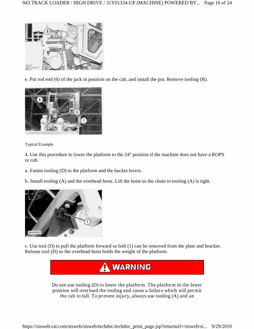
e. Put rod end (6) of the jack in position on the cab, and install the pin. Remove tooling (B).
Typical Example
4. Use this procedure to lower the platform to the 24° position if the machine does not have a ROPSor cab.
a. Fasten tooling (D) to the platform and the bucket levers.
b. Install tooling (A) and the overhead hoist. Lift the hoist so the chain to tooling (A) is tight.
c. Use tool (D) to pull the platform forward so bolt (1) can be removed from the plate and bracket.Release tool (D) so the overhead hoist holds the weight of the platform.
Do not use tooling (D) to lower the platform. The platform in the lowerposition will overload the tooling and cause a failure which will permit
the cab to fall. To prevent injury, always use tooling (A) and an
Page 16 of 24943 TRACK LOADER / HIGH DRIVE / 31Y01334-UP (MACHINE) POWERED BY...
9/29/2010https://sisweb.cat.com/sisweb/sisweb/techdoc/techdoc_print_page.jsp?returnurl=/sisweb/si...

overhead hoist to lower the platform. Use tooling (D) only to pull theplatform forward to remove bolt (1) from the plate and bracket.
d. Use tooling (A) and the overhead hoist to lower the platform. As the platform is lowered, hold bar(3) for the governor control in alignment with tube (2) so the bar will slide into the tube.
e. With the platform in the 24° position, install support bolts (5).
f. Put the rod end (4) of the jack in position, and install pin. Remove tooling (A) and (D).
Page 17 of 24943 TRACK LOADER / HIGH DRIVE / 31Y01334-UP (MACHINE) POWERED BY...
9/29/2010https://sisweb.cat.com/sisweb/sisweb/techdoc/techdoc_print_page.jsp?returnurl=/sisweb/si...
5. Remove plate (6) and bracket (7) from the front of the cab, and return them to their storage locationin the tool box.
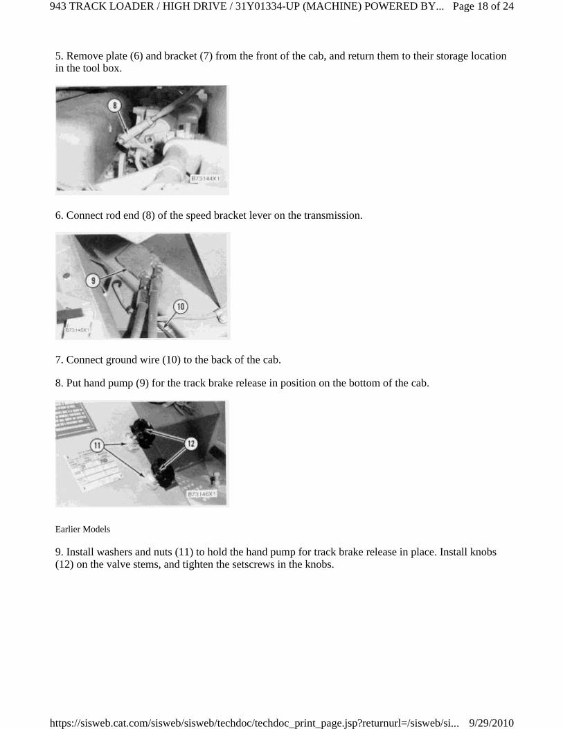
6. Connect rod end (8) of the speed bracket lever on the transmission.
7. Connect ground wire (10) to the back of the cab.
8. Put hand pump (9) for the track brake release in position on the bottom of the cab.
Earlier Models
9. Install washers and nuts (11) to hold the hand pump for track brake release in place. Install knobs(12) on the valve stems, and tighten the setscrews in the knobs.
Page 18 of 24943 TRACK LOADER / HIGH DRIVE / 31Y01334-UP (MACHINE) POWERED BY...
9/29/2010https://sisweb.cat.com/sisweb/sisweb/techdoc/techdoc_print_page.jsp?returnurl=/sisweb/si...
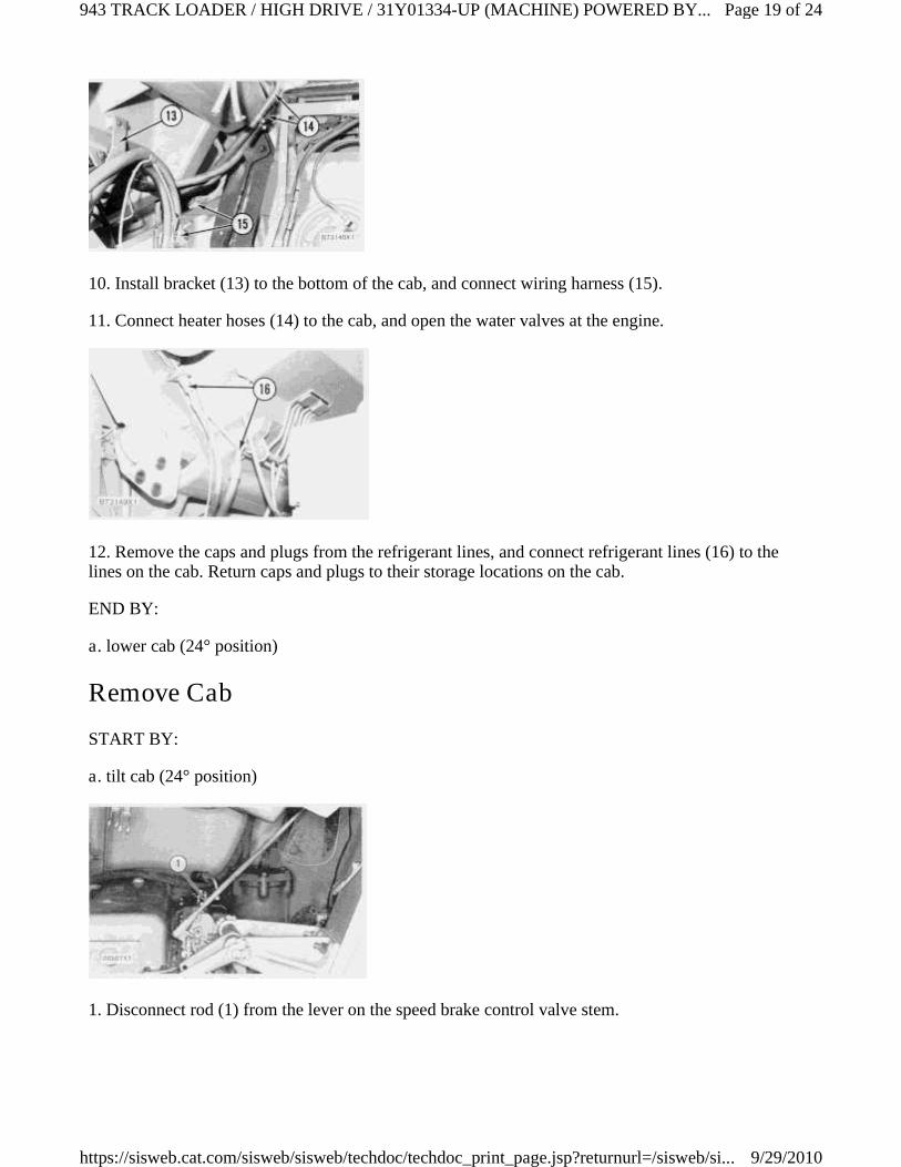
10. Install bracket (13) to the bottom of the cab, and connect wiring harness (15).
11. Connect heater hoses (14) to the cab, and open the water valves at the engine.
12. Remove the caps and plugs from the refrigerant lines, and connect refrigerant lines (16) to thelines on the cab. Return caps and plugs to their storage locations on the cab.
END BY:
a. lower cab (24° position)
Remove Cab
START BY:
a. tilt cab (24° position)
1. Disconnect rod (1) from the lever on the speed brake control valve stem.
Page 19 of 24943 TRACK LOADER / HIGH DRIVE / 31Y01334-UP (MACHINE) POWERED BY...
9/29/2010https://sisweb.cat.com/sisweb/sisweb/techdoc/techdoc_print_page.jsp?returnurl=/sisweb/si...
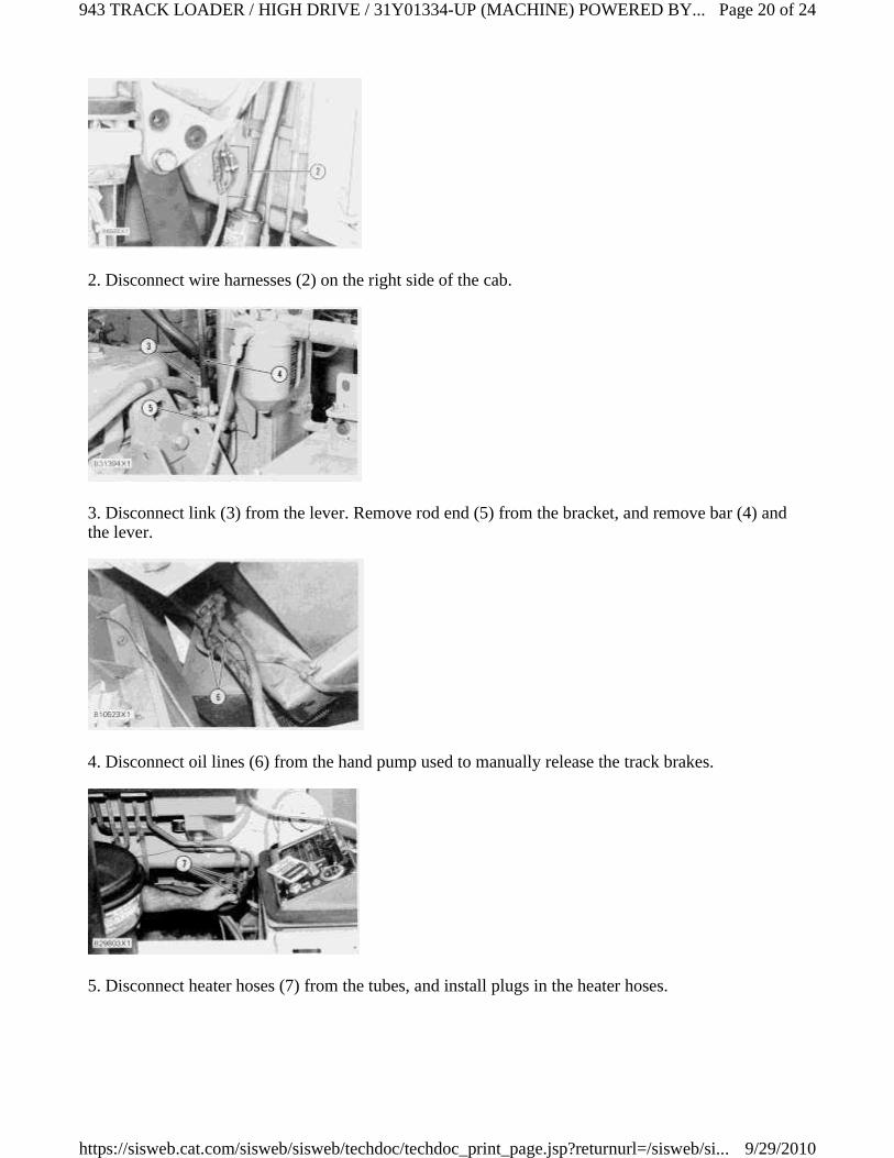
2. Disconnect wire harnesses (2) on the right side of the cab.
3. Disconnect link (3) from the lever. Remove rod end (5) from the bracket, and remove bar (4) andthe lever.
4. Disconnect oil lines (6) from the hand pump used to manually release the track brakes.
5. Disconnect heater hoses (7) from the tubes, and install plugs in the heater hoses.
Page 20 of 24943 TRACK LOADER / HIGH DRIVE / 31Y01334-UP (MACHINE) POWERED BY...
9/29/2010https://sisweb.cat.com/sisweb/sisweb/techdoc/techdoc_print_page.jsp?returnurl=/sisweb/si...
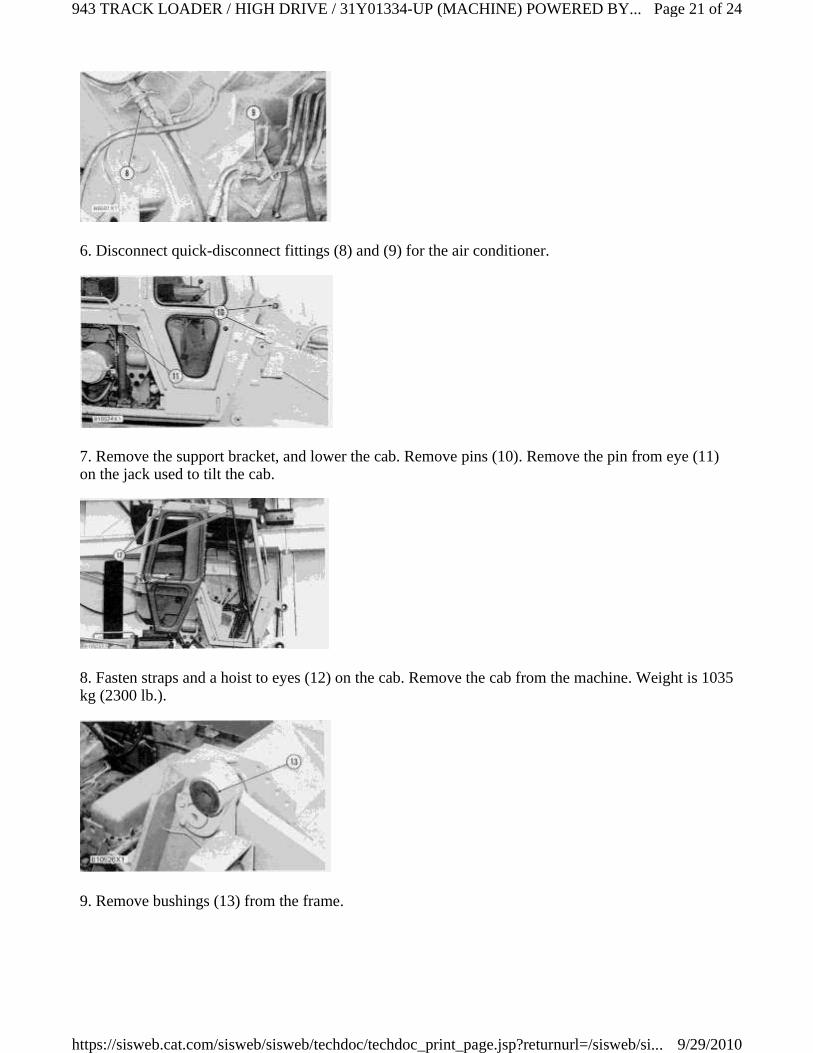
6. Disconnect quick-disconnect fittings (8) and (9) for the air conditioner.
7. Remove the support bracket, and lower the cab. Remove pins (10). Remove the pin from eye (11)on the jack used to tilt the cab.
8. Fasten straps and a hoist to eyes (12) on the cab. Remove the cab from the machine. Weight is 1035kg (2300 lb.).
9. Remove bushings (13) from the frame.
Page 21 of 24943 TRACK LOADER / HIGH DRIVE / 31Y01334-UP (MACHINE) POWERED BY...
9/29/2010https://sisweb.cat.com/sisweb/sisweb/techdoc/techdoc_print_page.jsp?returnurl=/sisweb/si...
Install Cab
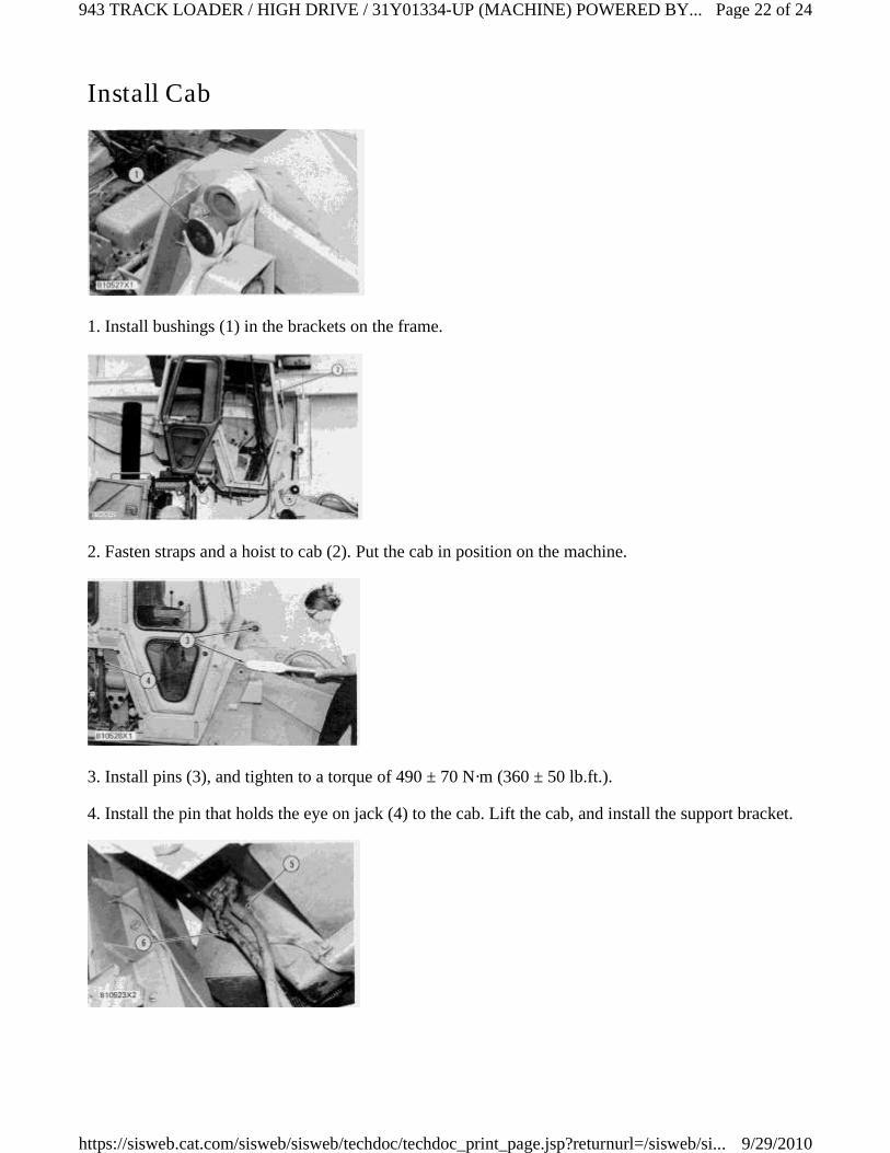
1. Install bushings (1) in the brackets on the frame.
2. Fasten straps and a hoist to cab (2). Put the cab in position on the machine.
3. Install pins (3), and tighten to a torque of 490 ± 70 N·m (360 ± 50 lb.ft.).
4. Install the pin that holds the eye on jack (4) to the cab. Lift the cab, and install the support bracket.
Page 22 of 24943 TRACK LOADER / HIGH DRIVE / 31Y01334-UP (MACHINE) POWERED BY...
9/29/2010https://sisweb.cat.com/sisweb/sisweb/techdoc/techdoc_print_page.jsp?returnurl=/sisweb/si...
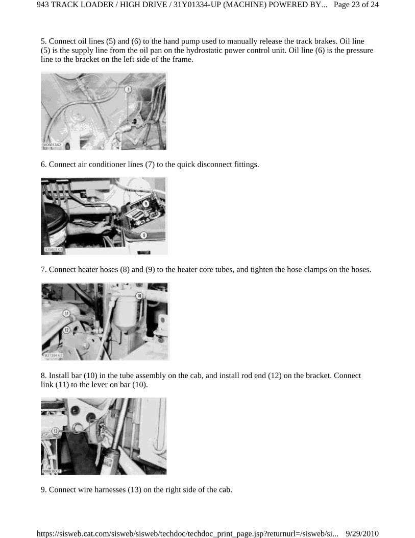
5. Connect oil lines (5) and (6) to the hand pump used to manually release the track brakes. Oil line(5) is the supply line from the oil pan on the hydrostatic power control unit. Oil line (6) is the pressureline to the bracket on the left side of the frame.
6. Connect air conditioner lines (7) to the quick disconnect fittings.
7. Connect heater hoses (8) and (9) to the heater core tubes, and tighten the hose clamps on the hoses.
8. Install bar (10) in the tube assembly on the cab, and install rod end (12) on the bracket. Connectlink (11) to the lever on bar (10).
9. Connect wire harnesses (13) on the right side of the cab.
Page 23 of 24943 TRACK LOADER / HIGH DRIVE / 31Y01334-UP (MACHINE) POWERED BY...
9/29/2010https://sisweb.cat.com/sisweb/sisweb/techdoc/techdoc_print_page.jsp?returnurl=/sisweb/si...
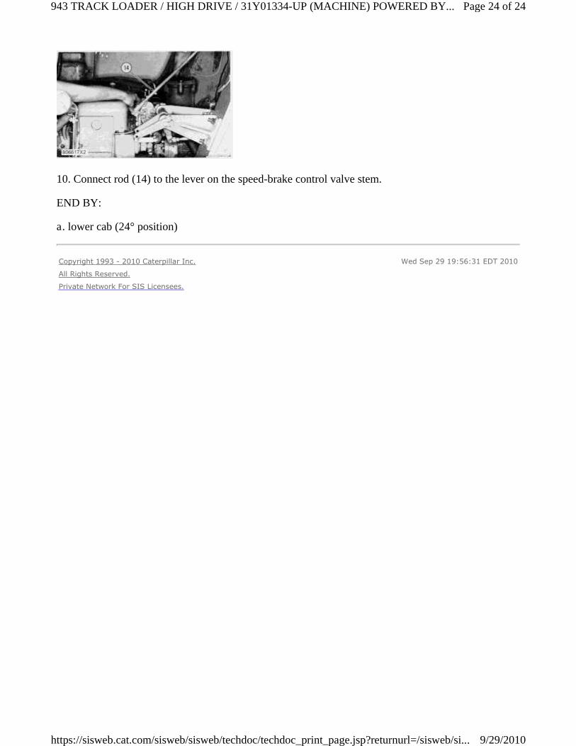
10. Connect rod (14) to the lever on the speed-brake control valve stem.
END BY:
a. lower cab (24° position)
Copyright 1993 - 2010 Caterpillar Inc.
All Rights Reserved.
Private Network For SIS Licensees.
Wed Sep 29 19:56:31 EDT 2010
Page 24 of 24943 TRACK LOADER / HIGH DRIVE / 31Y01334-UP (MACHINE) POWERED BY...
9/29/2010https://sisweb.cat.com/sisweb/sisweb/techdoc/techdoc_print_page.jsp?returnurl=/sisweb/si...