Embed Size (px)
Citation preview
( (i) cEMTREX G ALVANIC
A PPLIED
SciENCES INC.
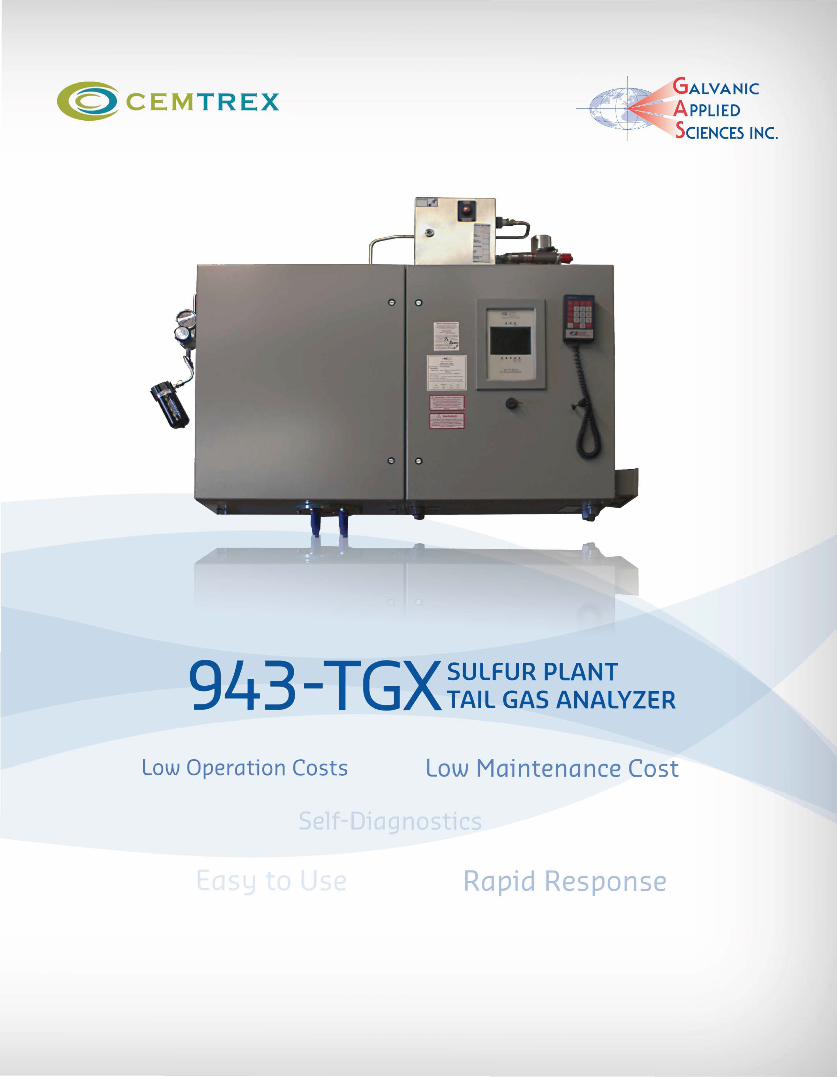
943 TGXSULFUR PLANT - TAIL GAS ANALYZER
Low Operation Costs Low Maintenance Cost
Rapid Response
The Galvanic Applied Sciences Leadership continues The Brimstone Sulfur UV Spectrophotometer product line is specially designed to measure sulfur species gas for sulfur recovery and other related processes. Using a holographic grating spectrometer coupled with a 2048 pixel UV enhanced CCO array, Galvanic's Brimstone online analyzers provide accurate, real-time analysis of the desired sulfur species .
THE BRIMSTONE 943 -TGX
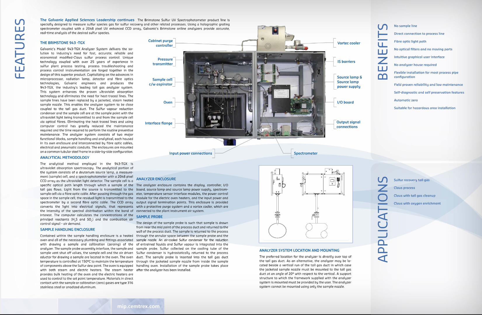
Galvanic's Model 943-TGX Analyzer System delivers the solution to industry's need for fast, accurate, reliable and economical modified-Claus sulfur process control. Unique technology coupled with over 25 years of experience in sulfur plant process testing, process troubleshooting and process control instrumentation are forged together in the design of this superior product. Capitalizing on the advances in microprocessor, radiation lamp, detector and fibre optics technologies, Galvanic engineers and produces the 943-TGX, the industry 's leading tail gas analyzer system . This system enhances the proven ultraviolet absorption technology and eliminates the need for heat-traced lines. The sample lines have been replaced by a jacketed, steam heated sample nozzle. This enables the analyzer system to be close coupled to the tail gas duct. The Sulfur vapour reduction condenser and the sample cell are at the sample point with the ultraviolet light being transmitted to and from the sample cell via optical fibres. Eliminating the heat traced lines and using computer control has greatly reduced the maintenance required and the time required to perform the routine preventive maintenance. The analyzer system consists of two major functional blocks, sample handling and analytical, each housed in its own enclosure and interconnected by fibre optic cables, electrical and pneumatic conduits. The enclosures are mounted on a common tubular steel frame in a side-by-side configuration.
ANALYTICAL METHODOLOGY
The analytical method employed in the 943-TGX is ultraviolet absorption spectroscopy . The analytical portion of the system consists of a deuterium source lamp, a measure-
Cabinet purge
controller
Pressure
transmitter
Sample cell
c/w aspirator
Oven
Interface flange
Input power connections
ment (sample) cell , and a spectrophotometer with a 2048 pixel ANALYZER ENCLOSURE CCD array as the ultraviolet light detector. The sample cell is a specific optical path length through which a sample of the The analyzer enclosure contains the display, controller, 1/0 tail gas flows . Light from the source is transmitted to the board, source lamp and source lamp power supply, spectromsample cell via a fibre optic cable. After passing through the gas eter, temperature sensor interface modules, the power control space in the sample cell , the residual light is transmitted to the module for the electric oven heaters, and the input power and spectrometer by a second fibre optic cable. The CCO array output signal termination points. This enclosure is provided converts the light into electrical signals, that represents with a protective purge system and a vortex cooler, which are the intensity of the spectral distribution within the band of connected to the plant instrument air system.
interest. The computer calculates the concentrations of the SAMPLE PROBE principal reactants (H 2S and SOJ and the combustion air control signal -air demand . The design of the sample probe is such that sample is drawn
SAMPLE HANDLING ENCLOSURE
Contained within the sample handling enclosure is a heated oven and all of the necessary plumbing and fittings associated with drawing a sample and calibration (zeroing) of the analyzer. The sample probe assembly interface, the sample and
from near the mid point of the process duct and returned to the wall of the process duct. The sample is returned to the process through the annular space between the sample probe and the sample nozzle. An air-cooled Sulfur condenser for the reduction of entrained liquids and Sulfur vapour is integrated into the sample probe. Sulfur collected on the cooling tube of the
sample vent shut off valves, the sample cell and the air driven Sulfur condenser is hydrostatically returned to the process eductor for drawing a sample are located in the oven. The oven duct. The sample probe is inserted into the tail gas duct temperature is controlled at 150°C to maintain the temperature through the jacketed sample nozzle from inside the sample of components above the Sulfur dew point. The oven is equipped handling oven . Installation of the sample probe takes place with both steam and electric heaters . The steam heater after the analyzer has been installed . provides bulk heating of the oven and the electric heaters are used to control to the set point temperature. Materials in direct contact with the sample or calibration (zero) gases are type 316 stainless steel or anodized aluminum.
Vortec cooler
IS barriers
Source lamp & Source lamp
power supply
1/0 board
Output signal
connections
ANALYZER SYSTEM LOCATION AND MOUNTING
The preferred location for the analyzer is directly over top of the tail gas duct. As an alternative, the analyzer may be located beside a vertical run of the tail gas duct in which case the jacketed sample nozzle must be mounted to the tail gas duct at an angle of 20° with respect to the vertical. A support structure to which the framework supplied with the analyzer system is mounted must be provided by the user. The analyzer system cannot be mounted using only the sample nozzle .
ll1 I--lL UJ z UJ OJ
ll1 z 0 -~ u -_J
a.. a.. <(
No sample line
Direct connection to process line
Fibre optic light path
No optical filters and no moving parts
Intuitive graphical user interface
No analyzer house required
Flexible installation for most process pipe configuration
Field proven reliability and low maintenance
Self-diagnostic and self preservation features
Automatic zero
Suitable for hazardous area installation
Sulfur recovery tail gas
Claus process
Claus with tail gas cleanup
Claus with oxygen enrichment
l/1 z 0 -~ u -lL -u UJ 0... l/1
0 N
~
"' :J
"' :J <(
> u.J a:
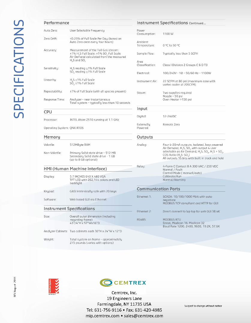
Performance Instrument Specifications continued ...
Auto Zero: User Selectable Frequency
Zero Drift: <0.25% of Full Scale Per Day (based on Auto Zero once every four hours)
Accuracy: Measurement of the Tail Gas stream: ±1% H,S Full Scale; ±1% SO, Full Scale Air Demand calculated from the measured H
2S and 50
2
Sensitivity: H2S reading :!:1% Full Scale
502
reading :!:1% Full Scale
Linearity: H2S :!:1% Full Scale
502
±1% Full Scale
Repeatability: :!:1% of Full Scale (with all species present)
Response Time: Analyzer- near instantaneous Total system- typically less than 10 seconds
CPU
Processor: INTEL Atom Z510 running at 1.1 GHz
Operating System: QNX RTOS
Memory
Volatile:
Non-Volatile:
512MByte RAM
Primary Solid state drive-512MB Secondary Solid state drive -1 GB (up to 8 GB optional)
HMI (Human Machine Interface)
Display: 5.7 INCHES 640 X 480 VGA TFT LCD with 262,144 colors and LED backlight
Power Consumption:
Ambient Temperature:
Sample Flow:
Area Classification:
Electrical:
Instrument Air:
Steam:
Input
Digital:
Externally Powered:
Outputs
Analog:
Relay:
1100 w
0 °C to 50 °C
Typically less than 5 SCFH
Class I Division 2 Groups C & D T3
1 00/240V- 10- 50/60 Hz- 11 OOW
22 SCFM at 80 psi (maximum case with vortec cooler at 20SCFM)
Two supplies required Nozzle - 50 psi Oven Heater > 150 psi
12-24VDC
Remote Zero
Four 4-20mA outputs, isolated, loop powered Air Demand, H25, 502 with output 4 user selectable as Air Demand, H25, 502, H25 + 502,
cos Ratio (H 2S: 502)
All outputs 16 bits with built in track and hold
4-Form C Contact 8 A 300 VAC I 250 VDC Normal I Fault Control Mode (manual/auto) Calibrate/Run Normal/Warning
Keypad: GASI intrinsically safe with 20 keys Communication Ports
Ethernet 1: Software: Web based GUI via Ethernet
Instrument Specifications Ethernet 2:
Size: Overall outer dimension (including mounting frame) 431/4"H x 57"Wx16"D
R5485:
Analyzer Cabinets: Two cabinets each 30"H x 24"W x 12"D
Weight:
I
Total system on frame- approximately 275 pounds (varies with options)
<C) cEMTREX
Cemtrex, Inc. 19 Engineers Lane
Farmingdale, NY 11735 USA Tel: 631-756-9116 • Fax: 631-420-4985
mip.cemtrex.com • [email protected]
SCADA: 10/100/1000 Mbit with auto negotiate MODBUS TCP compliant and HTIP for GUI
Direct connect to lap top for web GUI 38.4K
MODBUS RTU Enron, Modicon 16, Modicon 32 Baud Rate 1200, 2400, 9600, 19.2K, 57.6K
Subject to change without notice