Embed Size (px)
Citation preview
J33 - 1
1 Vice President, Sinotech Engineering Consultants, Ltd., Taiwan, Tel.: 02-27692131-21250, e-mail: [email protected] 2 Technical Manager, Sinotech Engineering Consultants, Ltd., Taiwan, Tel.: 02-27692131-21271, e-mail: [email protected] 3 Professional Engineer, Sinotech Engineering Consultants, Ltd., Taiwan, Tel.: 02-27692131-21204, e-mail: [email protected]
DESIGN OF NEW WUCHIEH AND LISHI CREEK TRANSBASIN TUNNELS
Chi-Tso CHANG1, Chung-Ren HUANG2, Hong-Shiang LIU3
ABSTRACT
The purpose of the New Wuchieh and Lishi Creek Transbasin Tunnel Project was to construct an additional tunnel system connecting the existing Wuchieh Dam and the new Lishi Dam to the Sun-Moon Lake Reservoir, parallel to the existing transbasin tunnel which was built more than 70 years ago. The tunnel is 15.7km in length. The section of the Main Tunnel from Adit C to the Muchilan Creek, about 7.1 km in length, was bored with a TBM, while the remainder of the length of the tunnel was excavated by means of the conventional drill and blast method. To explore the section bored by the TBM, one horizontal and three inclined long geological exploration holes about 400m~900m in length were drilled to explore the geological conditions along the tunnel profile. This kind of long hole drilling was a first in terms of geological exploration for tunnelling. Many new measures and construction materials were adopted in order to meet the demands of fast tunnel excavation and flexibility in support. These measures included expansion shell rock bolts, self-drilling rock bolts, steel fiber reinforced shotcrete, steel pipe roofing, steel bar forepiling pipes and lattice girders. Because of these measures, the construction of the tunnel went smoothly. For the especially difficult sections, five newly combined construction methods for the TBM and another five for the D&B method were recommended. In addition, the Contractor was provided the option of choosing construction methods that best suited the situation, and was in position to submit constructive plans which upon approval from the Client, could have been executed during engineering construction. Keywords: D&B method, TBM method, fast tunnel excavation and supporting, special difficulty
INTRODUCTION
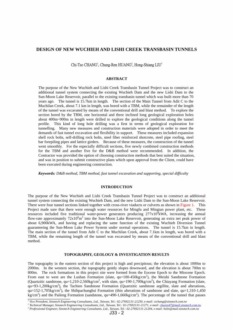
The purpose of the New Wuchieh and Lishi Creek Transbasin Tunnel Project was to construct an additional tunnel system connecting the existing Wuchieh Dam, and the new Lishi Dam to the Sun-Moon Lake Reservoir. There were four tunnel sections linked together with cross-river viaducts or culverts as shown in Figure 1. This Project made sure that there were enough water resources for Mingfu and Mingtan power plant, etc. These resources included five traditional water-power generators producing 277x104kWA, increasing the annual flow-rate approximately 72x106m3 into the Sun-Moon Lake Reservoir, generating an extra net peak power of about 6,900kWA, and having and replacing the same function of the existing Wuchieh Diversion Tunnel guaranteeing the Sun-Moon Lake Power System under normal operations. The tunnel is 15.7km in length. The main section of the tunnel from Adit C to the Muchilan Creek, about 7.1km in length, was bored with a TBM, while the remaining length of the tunnel was excavated by means of the conventional drill and blast method.
TOPOGRAPHY, GEOLOGY & INVESTIGATION RESULTS
The topography in the eastern section of this project is high and precipitous; the elevation is about 1000m to 2000m. In the western section, the topography gently slopes downward, and the elevation is about 700m to 800m. The rock formations in this project site were formed from the Eocene Epoch to the Miocene Epoch. From east to west are the Lushan Formation (slate, qu=100-450kg/cm2), the Meishi Sandstone Formation (Quartzitic sandstone, qu=1,210-2,560kg/cm2, with slate, qu=190-1,700kg/cm2), the Chiayang Formation (slate, qu=93-1,200kg/cm2), the Tachien Sandstone Formation (Quartzitic sandstone argillite, slate and alterations, qu=152-1,705kg/cm2), the Shihpachunghsi Formation (thin alterations of sandstone and slate, qu=1,310-1,450 kg/cm2) and the Paileng Formation (sandstone, qu=490-1,660kg/cm2). The percentage of the tunnel that passes
J33 - 2
through sandstone and slate is about 33% and 67%, respectively. The geological plan and profile along the tunnel are shown in Figure 1. (SEC, .2000) In this Project Site the major geological formations and structures are the Wuchieh Fault, the Lishan Structure and the Dili Fault. The Wuchieh Fault is inferred from the route and shape of the photographic map. It could have been a fracture zone or an extremely large water ingress zone. The area near the Lishan Structure was a densely folded and fractured zone and extremely large water ingress area. The Dili Fault and its accompanying fault line are mainly composed of the fractured zone, fault gouge and breccia. In the Basic Design stage for the TBM section, there were four long geological boreholes, 2,406.5 m in total length. This included one long horizontal borehole near the downstream Portal of the TBM Tunnel, 901.5 m in length(TB1-1). There were three 45° inclined boreholes along the TBM alignment, the 370 m (TB1-2), the 735 m (TB1-3) and the 400 m (TB1-4). A total of 23 geological boreholes totalling 3,622.5 m in length were drilled for the geological exploration in the areas of the portal, the other structures of D&B section, and the major geological formations of this Project Site. According to the above-mentioned borehole exploration results, the bedrock inside the first 250 m of the entrances of both the upstream and downstream portals of the TBM Tunnel were easily decomposed and weathered. They were designated as having medium to highly fractured weathering, and they also easily encountered the problem of large water ingress. From the horizontal borehole (TB1-1) of the downstream portal of the TBM Tunnel the maximum inflow rate of groundwater was measured at up to 1,400 l/min during the borehole drilling. Inside the first 200m of the entrance of the TBM portal a large inflow was encountered during the tunnel excavation. After passing this extremely large water ingress, no large inflow was observed in the next 2 km of tunnelling works. Rock mechanics testing included uniaxial testing, triaxial compression testing, dynamic/static elastic testing, direct shear testing, total hardness and petrographic examination testing, etc. These are tabulated in Table 1. (Lee et al. 1998)
Table 1 Rock Testing Results of the TBM Tunnel
FormationTest Item
Chiayang Formation Tachien Sandstone
Uniaxial Compression Strength( kg/cm2 ) 305∼1,200 429∼1,705 Static Elastic Velocity( m/sec ) 3,476∼5,072 3,266∼5,071
Total Hardness 21∼31 64∼144 Quartz Content( % ) 32∼42 54∼87
Based on the above-mentioned geological investigation results and evaluation, the rock mass classification and section percentage of the TBM Section (approximately 7.1 km) and D&B Section (approximately 8.6 km) along the tunnel alignment are tabulated in Table 2.
Table 2 Rock Mass Classification along Tunnel Profile
Class No. Ⅰ Ⅱ Ⅲ Ⅳ Ⅴ Q > 10 4 ~ 10 1 ~ 4 1 ~ 0.1 < 0.1
Rock mass
Rating RMR > 65 64 ~ 57 56 ~ 44 43 ~ 23 < 22
Special Geology
TBM 10 21 31 17 15 6 Tunnel Section
(%) D&B 8 10 20 26 25 11
J33 - 3
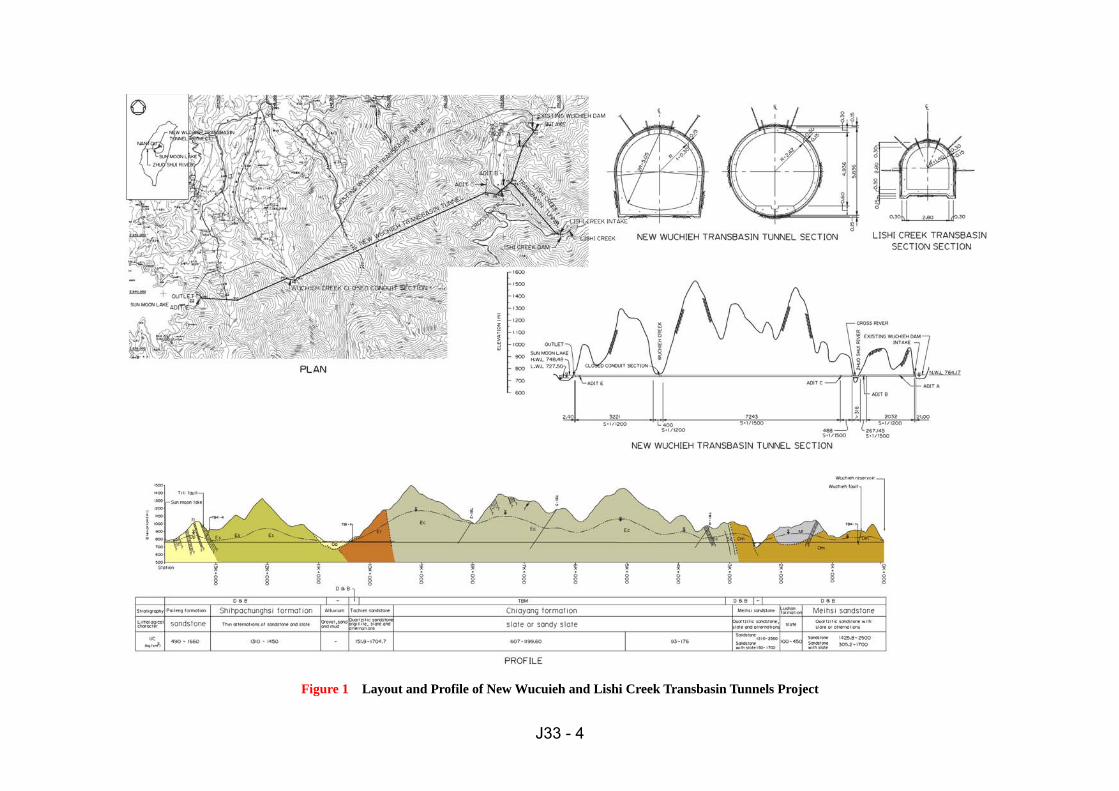
Figure 1 Layout and Profile of New Wucuieh and Lishi Creek Transbasin Tunnels Project
J33 - 4
D&B TUNNEL EXCAVATION & SUPPORT DESIGN
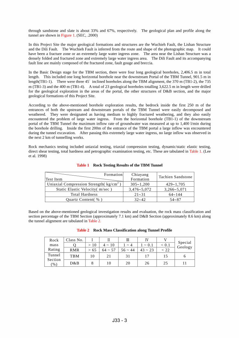
Tunnel Layouts and Typical Sections The New Wuchieh Tunnel is a gravity trans-water tunnel. The tunnel section and profile gradient was determined and confirmed from the results of hydraulic analysis. The designed flow rate is about 41.6~45.6 cms. The inner diameter of the horseshoe-shaped tunnel is about 4.70~5.05m. The profile gradient is approximately 1/1,200~1/1,500, and the tunnel is lined with reinforced concrete 30~40cm in thickness. The flow rate of the Lishi Creek Transbasin Tunnel is designed to be 9.0cms. This section of tunnel used reverse D type, 2.80m in width and height. The profile gradient is approximately 1/333, and the tunnel is lined with reinforced concrete 30 cm in thickness. Excavation and Support Design The excavation and support design of the D&B section was based on NGI-Q and RMR methods classified with the five types shown in Figure 2. Many new measures were adopted in the design drawings and specifications to apply the new tunnel construction concept of flexible construction and to apply new materials. These are described as follows. 1. To improve the convenience for vehicles, the muck output efficiency, the excavation face stability and the
tunnelling environment, the inverts with fc’=175kg/cm2 concrete were placed throughout the whole tunnel as required and instructed by Engineer.
2. In consideration of the Contractor’s independence and preferred construction techniques, support type IV was separated to type IV-A and IV-B so the Contractor could choose. Type IV-A was assigned to be an reverse D section with the support material being steel ribs and steel fiber reinforced shotcrete. Type IV-B was assigned to be a horseshoe-shaped section with the support material being rock bolts and steel fiber reinforced shotcrete.
3. In consideration of the Contractor’s independence and preferred construction techniques, the Contractor could choose the appropriate supports such as the rock bolt type (SN rock bolt or resin rock bolt or Hardi rock bolt, Swelllex rock bolt or self-drilled rock bolt) as instructed by engineer. Steel fiber reinforced shotcrete could be replaced by shotcrete with wire mesh equivalent to the thickness of design drawings. H shaped or lattice girder steel ribs could also be used. The material type of the forepiling was to be specified by the engineer as: #11 steel bars, 40mm∮steel pipe, injection resin pipe, self-drilled rock bolt or channel shaped steel bar.
For any of the following cases in which the tunnel excavations were especially difficult in which the typical standard supports could not be applied and doing the special treatments was confirmed by the Client: 1. To go through the fractured, non-cohesive or unusual pressure of squeezing strata, no typical standard supports
could be applied. 2. To conduct the site improvement in the working face of tunnel excavations or additional pilot tunnel. 3. To proceed no further in excavation works while the inflow rate was over 100 l/sec and there was high water
pressure. 4. To have the existence of gas or noxious gas, and the concentrated air was measured to be dangerous to the
health of workers or construction safety, and there was no improvement after all evacuating measures and enlargement of the ventilation system.
For the abovementioned especially difficult sections of the tunnel works, the Contractor had to submit the construction plans. In the design stage, the five types of supports also could be appropriately combined and placed as shown in Figure 3. The Contractor could design his own methods. The Contractor could choose and use any appropriate combination of the several additional auxiliary measures such as steel pipes roofing, forepiling steel pipe, seal-water/air grouting, consolidation grouting, check-hole with drainage, drainage belt, face steel fiber reinforced shotcrete, bench cutting, or ring cutting, bench steel fiber reinforced shotcrete, wing steel ribs and jet grouting pillar, etc. The Contractor needed to propose and conduct the additional construction plan (including the design drawings) of the additional pilot or by-pass tunnel, ventilation shaft, adit or special treatments if the Client approved.
J33 - 5
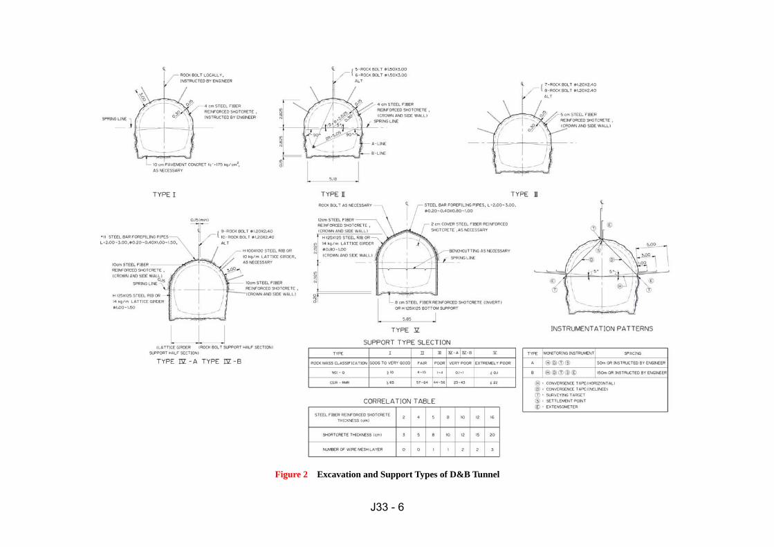
Figure 2 Excavation and Support Types of D&B Tunnel
J33 - 6
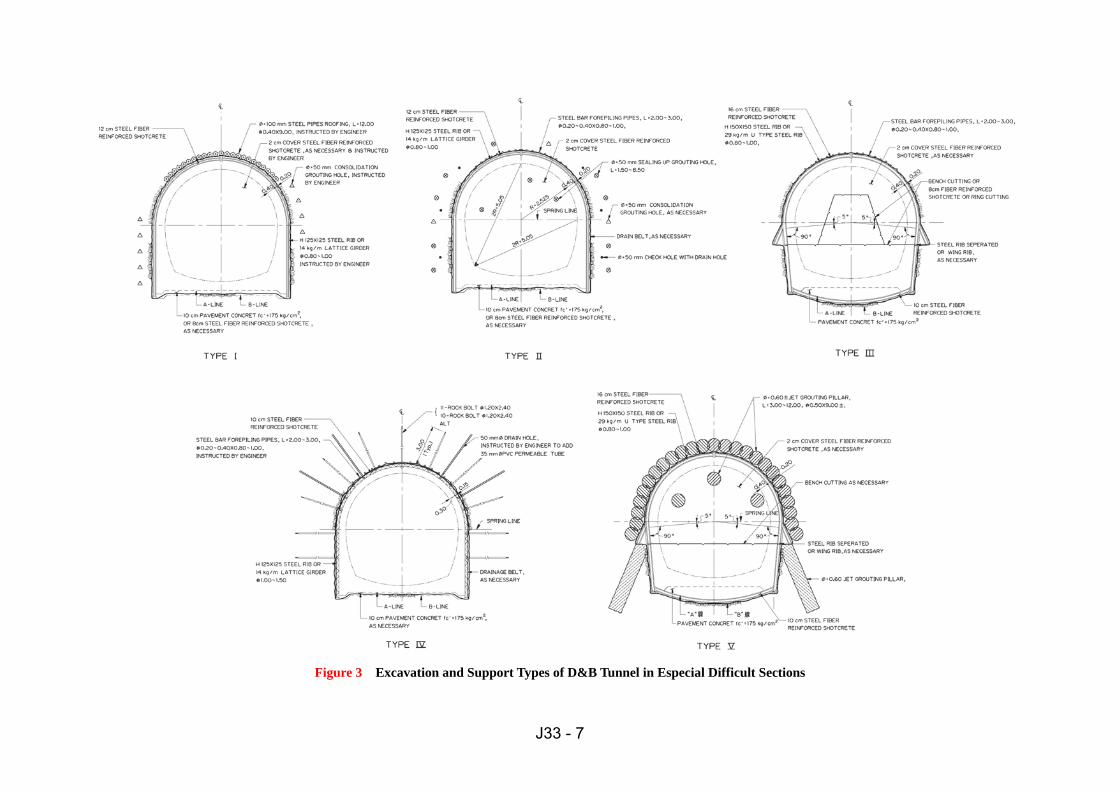
Figure 3 Excavation and Support Types of D&B Tunnel in Especial Difficult Sections
J33 - 7
TBM TUNNEL EXCAVATION & SUPPORT DESIGN
Tunnel Typical Section Due to the different types of TBM and TBM supports and the actual needs of the Contractor’s construction machines and experience, the following three cases were provided for the bidders to use to self-evaluate and make a choice: Case I open type TBM with cast-in-situ concrete lining; Case II open type TBM with precast concrete segments; Case III closed type TBM with precast concrete segments. The awarded Contractor, New Asia - Kumagai Joint Venture decided to use Case I. The TBM Tunnel section was designed as a gravity round section, with an inner diameter of 5.24 m, and a length of 7,114m. Its profile gradient was 1/1,500, and it had 30cm thickness reinforced concrete lining. Excavation and Support Design In the TBM excavation and support design, the Q and RMR classifications were generally adopted and divided up into the five types shown in Figure 4. During construction, the operator of the TBM could prejudge from the panel gauges, boring sound, the grain size and wetted degree of muck or bore hole information and choose the appropriate support type, and prepare the support materials. After the rock was exposed from the shield of the cutter head and the rock classification was confirmed, the operator could construct the support immediately. To meet the characteristics of open type TBM construction, the demand of fast excavation and support, new concept of flexible construction and the trends of new materials, design drawings and specifications were adopted with many combinations of construction measures. The main items are described as follows: 1. The Contractor proposed the construction plan of the diameter of the TBM and the lining thickness. After
approval by the Client, it was carried out. 2. The Contractor proposed the construction plan for excavating the cross section, the length and support types of
launching and the exit-terminal of the TBM chamber. After approval by the Client, it was carried out. 3. To have a safe, fast, economical and stable foundation for the TBM’s back-up system by the railroad, precast
invert segment with fc’=350kg/cm2 concrete were placed along the whole tunnel. Because the precast invert segments were only indicated for general construction use in the design drawings, the Contractor had to submit the detailed design drawings and specifications based on the model of TBM. After approval by Client, then it was carried out. The actual field dimensions of steel fiber plus rebar-mesh precast invert segments (including dimension changes) in the site cut down the large cost of the inverted segments.
4. In consideration of the Contractor’s independence and preferred construction techniques, the Contractor could choose the appropriate supports such as rock bolt type A: Hardi rock bolts or Swellex rock bolts at the section of L1. The Contractor could choose rock bolt type B: SN rock bolts or resin rock bolts at the section of L2. Steel fiber reinforced shotcrete could be replaced with shotcrete with wire mesh equivalent to the thickness of design drawings. H shaped or lattice girder steel ribs could be used. The material type of the forepiling steel pipe was to be designated by the Engineer as either #11 steel bar, 40mm∮steel pipe, injection resin pipe, self-drilled rock bolt or channel shaped steel bar.
5. In order to fit the TBM characteristics of fast construction, the workers safety was seriously considered except for that of instant supports. In the 90° range of the crown exposed after fresh rock was exposed, channel shaped steel rib with rock bolts type A and wire mesh were to be installed. In the full ring steel ribs with wire mesh were to be installed. Wire mesh was installed onto steel supports close to the rock face. Therefore the TBM method had the unique characteristic of using a large quantity of steel supports.
6. During TBM construction, geological exploration methods such as the in advance geological boreholes, the pre-drilled boring and the seismic surveys had to be conducted. To obtain at least 30 m of geological exploration in front of the TBM excavation face, all this geological information was evaluated and conducted to classify the rock types, and determine the excavation, support and reinforcing measures. If the abovementioned geological exploration was not completely done, a tunnel disaster and/or damage to the TBM’s equipment could be caused from the wrong geological judgements. All of the extra cost and working time to repair the TBM, the tunnel remediation and strengthening measures would have been unquestionably charged to the Contractor. To be fair and reasonable, the geological exploration work was exclusively paid for by the actual executive entities.
During the tunnel excavation, when especially difficult sections of tunnel work were recognized by the Client, the Contractor had to submit construction plans. In the design stage, the five types of construction methods could also be appropriately combined and placed as shown in Figure 5.
J33 - 8
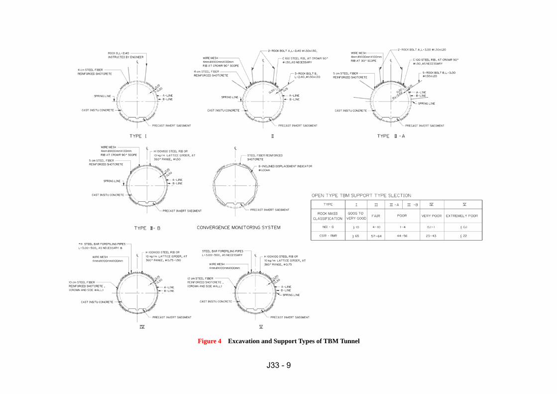
Figure 4 Excavation and Support Types of TBM Tunnel
J33 - 9
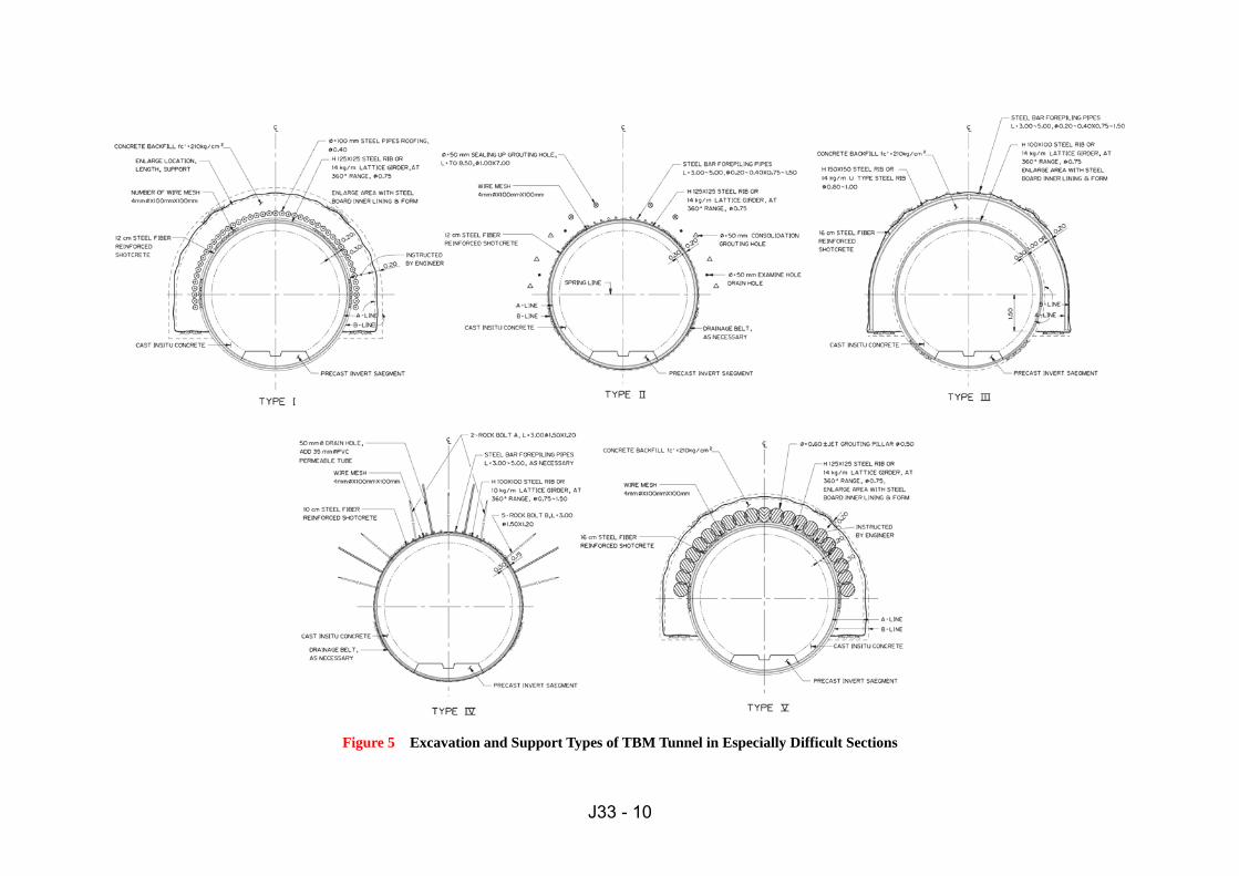
Figure 5 Excavation and Support Types of TBM Tunnel in Especially Difficult Sections
J33 - 10
There were several additional auxiliary measures used such as an enlarging the excavation area, steel pipes roofing, forepiling steel pipe, seal-water/air grouting, consolidation grouting, check-hole with drainage, drainage belt, and jet grouting pillars, etc. The Contractor could choose and use appropriate combinations of the auxiliary measures under special geological conditions.
CONCLUSIONS
The characteristics of the planning and design of this project are described as follows: 1. This was third TBM case in Taiwan where the geological and topographical conditions were appropriate to
apply the new construction methods and techniques of tunnelling. The New Wuchien Transbasin Tunnel from Adit C to the Muchilan Creek was originally proposed to use the conventional drill and blast method but this was changed to being bored with a TBM.
2. In the basic design stage for the TBM tunnel section, a horizontal borehole (901.5m in length) and three inclined long boreholes were drilled not only to have the geological information along the tunnel profile but also to create a new page in Taiwan’s geological exploration for tunnel engineering.
3. To meet the characteristics of D&B and TBM construction, the demand of fast excavation and support, new concepts of flexible construction and the trends in new materials, the design drawings and specifications were adopted with many combinations of construction measures to make the tunnel work go smoothly.
4. For the especially difficult sections of tunnel work, the Contractor had to submit an additional construction plan. In the design stage, five combined construction methods were also recommended. In addition, the Contractor was provided the option of choosing construction methods that best suited the situation, and was in a position to submit construction plans which upon approval from the Client, could be executed during construction.
REFERENCES
Sinotech Engineering Consultants, Ltd. (2000), ” Evaluation Report of The New Wuchieh and Lishi Creek Transbasin Tunnel Planning Project Geological Investigation & Rock Mechanics Tests ”, Taiwan Power Company. (In Chinese)
Lee, M. S., Lee, H. Z., Huang, W. G. and Liu, G. Z. (1998), ” Geological Report of The New Wuchieh Tunnel Project TBM Sections ”, Proceedings of Rock Engineering Symposium in Taiwan, pp. 539-548. (In Chinese)
J33 - 11