Embed Size (px)
Citation preview
9/230, 9/270, 9/300, 12/235, 17/235, 21/2159/230HA, 9/270HA, 9/300HA, 12/235HA, 17/235HA, 21/215HA
OPERATION AND MAINTENANCE MANUAL
This manual containsimportant safety informationand must be made available topersonnel who operate andmaintain this machine.
IR 9/230, 9/270, –>SERIAL No :
C.C.N. : 22163448 GBDATE : MARCH 2003
892000
IR 17/235, –>SERIAL No : 881000
9/300, 12/335
21/215
01/03
Machine models represented in this manual may be used in various locations world–wide. Machines sold and shippedinto European Union Territories require that the machine display the EC Mark and conform to various directives. Insuch cases, the design specification of this machine has been certified as complying with EC directives. Anymodification to any part is absolutely prohibited and would result in the CE Certification and marking being renderedinvalid. A declaration of that conformity follows:
We
Declare that, under our sole responsibility for manufacture and supply, the product(s)
98/37/EC, 93/68/EEC, 89/336/EEC, 2000/14/EC
Ingersoll–Rand Company Portable Compressor DivisionP.O. Box 868501 Sanford AvenueMocksville, North Carolina 27028
Ingersoll–Rand Company LimitedStandard Products DivisionSwan LaneHindley GreenWigan WN2 4EZUnited Kingdom
Represented in EC by:
to which this declaration relates, is (are) in conformity with the provisions of the above directives using the following principal standards
Issued at Mocksville on1–1–2003
EN29001 : EN292, EN60204–1, EN1012–1, PN8NTC2, EN50081 EN50082
________________________________
9/230, 9/270, 9/300, 12/235, 17/235, 21/215
Ric LunsfordManager of quality control
DECLARATION OF CONFORMITY WITH EC DIRECTIVES
CONFORMITY WITH NOISE DIRECTIVE 2000/14/ECIngersoll–Rand Company Limited declare that the following Portable Compressors have been
manufactured in conformity with the directive as shownMachine Serial number Mean measured GuaranteedDirective
Type kWSerial number
rangeMean measured
valueGuaranteed
Level Notified body
2000/14/EC 9/230 A V Technology2000/14/ECAnnex VI 9/270 224 892000–899999 100.3 LWA 102 LWA
A V TechnologyStockport UK
Part I 12/235WA WA
Nr 1067
2000/14/EC 9/300 A V Technology2000/14/ECAnnex VI 17/235 255 881000–889999 100.3 LWA 102 LWA
A V TechnologyStockport UK
Part I 21/215WA WA
Nr 1067
________________________________
Issued at Mocksville. . . . . . . . . . . 1st Declaration 18–02–03. . . . . Quality assurance manager
EC Pressure Equipment Directive and Related RegulationsWe declare that this product has been assessed according to the Pressure Equipment Directive (97/23/EC) and, inaccordance with the terms of this Directive, has been excluded from the scope of this Directive.It may carry ”CE” marking in compliance with other applicable EC Directives.
CONTENTS & ABBREVIATIONS 1
9/230, 9/270, 9/300, 12/235, 17/235, 21/215, 9/230HA, 9/270HA, 9/300HA, 12/235HA, 17/235HA, 21/215HA
CONTENTS
1 CONTENTS
2 FOREWORD
4 WARRANTY
11 ISO SYMBOLS
14 SAFETY
16 GENERAL INFORMATIONDimensionsData
19 OPERATING INSTRUCTIONSCommissioningPrior to startingStartingStoppingEmergency stoppingRe–startingMonitoring during operationDecommissioning
28 MAINTENANCERoutine maintenanceLubricationSpeed & pressure regulationTorque settings tableCompressor lubrication
40 MACHINE SYSTEMSElectrical systemPiping & instrumentation system
45 FAULT FINDING
47 OPTIONS
49 PARTS ORDERING
ABBREVIATIONS & SYMBOLS
#### Contact Ingersoll–Rand for serial number
–>#### Up to Serial No.####–> From Serial No.
* Not illustrated
† Option
WDG Generator option
AR As required
BR Brazil
CN China
DE Germany
DK Denmark
ES Spain
FI Finland
FR France
GB Great Britain (English)
HA High ambient machine
IT Italy
NL Holland
NO Norway
PT Portugal
SE Sweden
US United States
S.R.G. Site running gear
H.R.G. High speed running gear
FOREWORD2
9/230, 9/270, 9/300, 12/235, 17/235, 21/215, 9/230HA, 9/270HA, 9/300HA, 12/235HA, 17/235HA, 21/215HA
The contents of this manual are considered to be proprietary andconfidential to Ingersoll–Rand and should not be reproduced withoutthe prior written permission of Ingersoll–Rand.
Nothing contained in this document is intended to extend anypromise, warranty or representation, expressed or implied, regardingthe Ingersoll–Rand products described herein. Any such warranties orother terms and conditions of sale of products shall be in accordancewith the standard terms and conditions of sale for such products, whichare available upon request.
This manual contains instructions and technical data to cover allroutine operation and scheduled maintenance tasks by operation andmaintenance staff. Major overhauls are outside the scope of thismanual and should be referred to an authorised Ingersoll–Rand servicedepartment.
The design specification of this machine has been certified ascomplying with EC directives. As a result:
(a) Any machine modifications are strictly prohibited, and will invalidateEC certification.
(b) This machine may be used in USA / Canada, when configured withcomponents bearing the appropriate certification. (Where ASMEcertification is valid).
All components, accessories, pipes and connectors added to thecompressed air system should be:. of good quality, procured from a reputable manufacturer and,wherever possible, be of a type approved by Ingersoll–Rand.. clearly rated for a pressure at least equal to the machine maximumallowable working pressure.. compatible with the compressor lubricant/coolant.. accompanied with instructions for safe installation, operation andmaintenance.
Details of approved equipment are available from Ingersoll–RandService departments.
The use of repair parts / lubricants / fluids other than those includedwithin the Ingersoll–Rand approved parts list may create hazardousconditions over which Ingersoll–Rand has no control. ThereforeIngersoll–Rand cannot be held responsible for equipment in whichnon–approved repair parts are installed.
Ingersoll–Rand reserves the right to make changes andimprovements to products without notice and without incurring anyobligation to make such changes or add such improvements toproducts sold previously.
The intended uses of this machine are outlined below and examplesof unapproved usage are also given, however Ingersoll–Rand cannotanticipate every application or work situation that may arise.
IF IN DOUBT CONSULT SUPERVISION.
This machine has been designed and supplied for use only in thefollowing specified conditions and applications:. Compression of normal ambient air containing no known ordetectable additional gases, vapours. or particles. Operation within the ambient temperature range specified in theGENERAL INFORMATION section of this manual.
FOREWORD 3
9/230, 9/270, 9/300, 12/235, 17/235, 21/215, 9/230HA, 9/270HA, 9/300HA, 12/235HA, 17/235HA, 21/215HA
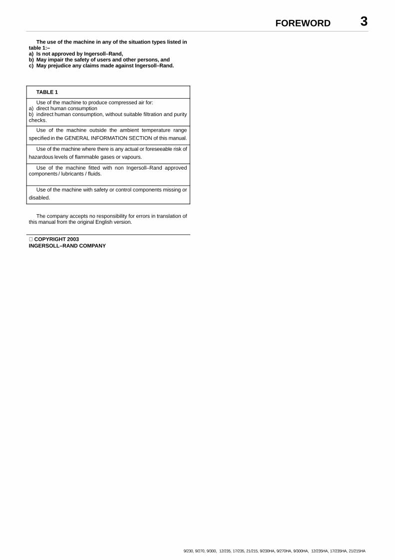
The use of the machine in any of the situation types listed intable 1:–a) Is not approved by Ingersoll–Rand,b) May impair the safety of users and other persons, andc) May prejudice any claims made against Ingersoll–Rand.
TABLE 1
Use of the machine to produce compressed air for:a) direct human consumptionb) indirect human consumption, without suitable filtration and puritychecks.
Use of the machine outside the ambient temperature range
specified in the GENERAL INFORMATION SECTION of this manual.
Use of the machine where there is any actual or foreseeable risk of
hazardous levels of flammable gases or vapours.
Use of the machine fitted with non Ingersoll–Rand approvedcomponents / lubricants / fluids.
Use of the machine with safety or control components missing or
disabled.
The company accepts no responsibility for errors in translation ofthis manual from the original English version.
COPYRIGHT 2003INGERSOLL–RAND COMPANY
WARRANTY4
9/230, 9/270, 9/300, 12/235, 17/235, 21/215, 9/230HA, 9/270HA, 9/300HA, 12/235HA, 17/235HA, 21/215HA
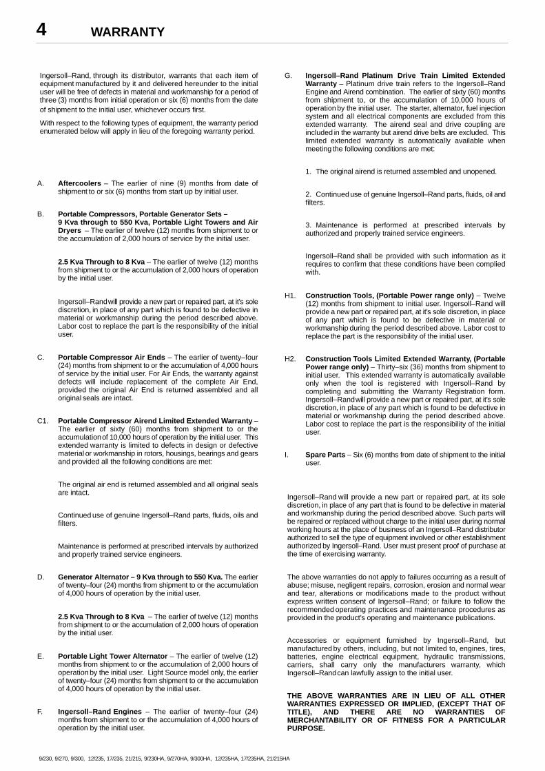
Ingersoll–Rand, through its distributor, warrants that each item ofequipment manufactured by it and delivered hereunder to the initialuser will be free of defects in material and workmanship for a period ofthree (3) months from initial operation or six (6) months from the dateof shipment to the initial user, whichever occurs first.
With respect to the following types of equipment, the warranty periodenumerated below will apply in lieu of the foregoing warranty period.
A. Aftercoolers – The earlier of nine (9) months from date ofshipment to or six (6) months from start up by initial user.
B. Portable Compressors, Portable Generator Sets –9 Kva through to 550 Kva, Portable Light Towers and AirDryers – The earlier of twelve (12) months from shipment to orthe accumulation of 2,000 hours of service by the initial user.
2.5 Kva Through to 8 Kva – The earlier of twelve (12) monthsfrom shipment to or the accumulation of 2,000 hours of operationby the initial user.
Ingersoll–Rand will provide a new part or repaired part, at it’s solediscretion, in place of any part which is found to be defective inmaterial or workmanship during the period described above.Labor cost to replace the part is the responsibility of the initialuser.
C. Portable Compressor Air Ends – The earlier of twenty–four(24) months from shipment to or the accumulation of 4,000 hoursof service by the initial user. For Air Ends, the warranty againstdefects will include replacement of the complete Air End,provided the original Air End is returned assembled and alloriginal seals are intact.
C1. Portable Compressor Airend Limited Extended Warranty –The earlier of sixty (60) months from shipment to or theaccumulation of 10,000 hours of operation by the initial user. Thisextended warranty is limited to defects in design or defectivematerial or workmanship in rotors, housings, bearings and gearsand provided all the following conditions are met:
The original air end is returned assembled and all original sealsare intact.
Continued use of genuine Ingersoll–Rand parts, fluids, oils andfilters.
Maintenance is performed at prescribed intervals by authorizedand properly trained service engineers.
D. Generator Alternator – 9 Kva through to 550 Kva. The earlierof twenty–four (24) months from shipment to or the accumulationof 4,000 hours of operation by the initial user.
2.5 Kva Through to 8 Kva – The earlier of twelve (12) monthsfrom shipment to or the accumulation of 2,000 hours of operationby the initial user.
E. Portable Light Tower Alternator – The earlier of twelve (12)months from shipment to or the accumulation of 2,000 hours ofoperation by the initial user. Light Source model only, the earlierof twenty–four (24) months from shipment to or the accumulationof 4,000 hours of operation by the initial user.
F. Ingersoll–Rand Engines – The earlier of twenty–four (24)months from shipment to or the accumulation of 4,000 hours ofoperation by the initial user.
G. Ingersoll–Rand Platinum Drive Train Limited ExtendedWarranty – Platinum drive train refers to the Ingersoll–RandEngine and Airend combination. The earlier of sixty (60) monthsfrom shipment to, or the accumulation of 10,000 hours ofoperation by the initial user. The starter, alternator, fuel injectionsystem and all electrical components are excluded from thisextended warranty. The airend seal and drive coupling areincluded in the warranty but airend drive belts are excluded. Thislimited extended warranty is automatically available whenmeeting the following conditions are met:
1. The original airend is returned assembled and unopened.
2. Continued use of genuine Ingersoll–Rand parts, fluids, oil andfilters.
3. Maintenance is performed at prescribed intervals byauthorized and properly trained service engineers.
Ingersoll–Rand shall be provided with such information as itrequires to confirm that these conditions have been compliedwith.
H1. Construction Tools, (Portable Power range only) – Twelve(12) months from shipment to initial user. Ingersoll–Rand willprovide a new part or repaired part, at it’s sole discretion, in placeof any part which is found to be defective in material orworkmanship during the period described above. Labor cost toreplace the part is the responsibility of the initial user.
H2. Construction Tools Limited Extended Warranty, (PortablePower range only) – Thirty–six (36) months from shipment toinitial user. This extended warranty is automatically availableonly when the tool is registered with Ingersoll–Rand bycompleting and submitting the Warranty Registration form.Ingersoll–Rand will provide a new part or repaired part, at it’s solediscretion, in place of any part which is found to be defective inmaterial or workmanship during the period described above.Labor cost to replace the part is the responsibility of the initialuser.
I. Spare Parts – Six (6) months from date of shipment to the initialuser.
Ingersoll–Rand will provide a new part or repaired part, at its solediscretion, in place of any part that is found to be defective in materialand workmanship during the period described above. Such parts willbe repaired or replaced without charge to the initial user during normalworking hours at the place of business of an Ingersoll–Rand distributorauthorized to sell the type of equipment involved or other establishmentauthorized by Ingersoll–Rand. User must present proof of purchase atthe time of exercising warranty.
The above warranties do not apply to failures occurring as a result ofabuse; misuse, negligent repairs, corrosion, erosion and normal wearand tear, alterations or modifications made to the product withoutexpress written consent of Ingersoll–Rand; or failure to follow therecommended operating practices and maintenance procedures asprovided in the product’s operating and maintenance publications.
Accessories or equipment furnished by Ingersoll–Rand, butmanufactured by others, including, but not limited to, engines, tires,batteries, engine electrical equipment, hydraulic transmissions,carriers, shall carry only the manufacturers warranty, whichIngersoll–Rand can lawfully assign to the initial user.
THE ABOVE WARRANTIES ARE IN LIEU OF ALL OTHERWARRANTIES EXPRESSED OR IMPLIED, (EXCEPT THAT OFTITLE), AND THERE ARE NO WARRANTIES OFMERCHANTABILITY OR OF FITNESS FOR A PARTICULARPURPOSE.
WARRANTY 5
9/230, 9/270, 9/300, 12/235, 17/235, 21/215, 9/230HA, 9/270HA, 9/300HA, 12/235HA, 17/235HA, 21/215HA
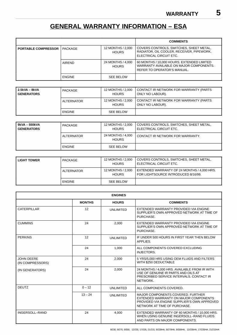
GENERAL WARRANTY INFORMATION – ESA
COMMENTS
PORTABLE COMPRESSOR PACKAGE 12 MONTHS / 2,000HOURS
COVERS CONTROLS, SWITCHES, SHEET METAL,RADIATOR, OIL COOLER, RECEIVER, PIPEWORK,ELECTRICAL CIRCUIT ETC.
AIREND 24 MONTHS / 4,000HOURS
60 MONTHS / 10,000 HOURS. EXTENDED LIMITEDWARRANTY AVAILABLE ON MAJOR COMPONENTS.REFER TO OPERATOR’S MANUAL.
ENGINE SEE BELOW
2.5kVA – 8kVAGENERATORS
PACKAGE 12 MONTHS / 2,000HOURS
CONTACT IR NETWORK FOR WARRANTY (PARTSONLY NO LABOUR).
ALTERNATOR 12 MONTHS / 2,000HOURS
CONTACT IR NETWORK FOR WARRANTY (PARTSONLY NO LABOUR).
ENGINE SEE BELOW
9kVA – 550kVAGENERATORS
PACKAGE 12 MONTHS / 2,000HOURS
COVERS CONTROLS, SWITCHES, SHEET METAL,ELECTRICAL CIRCUIT ETC.
ALTERNATOR 24 MONTHS / 4,000HOURS
CONTACT IR NETWORK FOR WARRANTY.
ENGINE SEE BELOW
LIGHT TOWER PACKAGE 12 MONTHS / 2,000HOURS
COVERS CONTROLS, SWITCHES, SHEET METAL,ELECTRICAL CIRCUIT ETC.
ALTERNATOR 12 MONTHS / 2,000HOURS
EXTENDED WARRANTY OF 24 MONTHS / 4,000 HRS.FOR LIGHTSOURCE INTRODUCED 8/16/99.
ENGINE SEE BELOW
ENGINES
MONTHS HOURS COMMENTS
CATERPILLAR 12 UNLIMITED EXTENDED WARRANTY PROVIDED VIA ENGINESUPPLIER’S OWN APPROVED NETWORK AT TIME OFPURCHASE.
CUMMINS 24 2,000 EXTENDED WARRANTY PROVIDED VIA ENGINESUPPLIER’S OWN APPROVED NETWORK AT TIME OFPURCHASE.
PERKINS 12 UNLIMITED IF UNDER 500 HOURS IN FIRST YEAR THEN BELOWAPPLIES.
24 1,000 ALL COMPONENTS COVERED EXCLUDINGINJECTORS.
JOHN DEERE(IN COMPRESSORS)
24 2,000 5 YRS/5,000 HRS USING OEM FLUIDS AND FILTERSWITH $250 DEDUCTABLE
(IN GENERATORS) 24 2,000 24 MONTHS / 4,000 HRS. AVAILABLE FROM IR WITHUSE OF GENUINE IR PARTS AND OILS ATPRESCRIBED SERVICE INTERVALS. CONTACT IRNETWORK.
DEUTZ 0 – 12 UNLIMITED ALL COMPONENTS COVERED.
13 – 24 UNLIMITED MAJOR COMPONENTS COVERED. FURTHEREXTENDED WARRANTY ON MAJOR COMPONENTSPROVIDED VIA ENGINE SUPPLIER’S OWN APPROVEDNETWORK AT TIME OF PURCHASE.
INGERSOLL–RAND 24 4,000 EXTENDED WARRANTY OF 60 MONTHS / 10,000 HRS.WHEN USING GENUINE INGERSOLL–RAND FLUIDSAND PARTS ON MAJOR COMPONENTS.
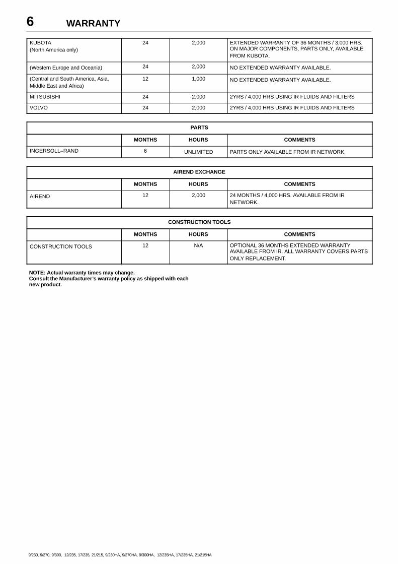
WARRANTY6
9/230, 9/270, 9/300, 12/235, 17/235, 21/215, 9/230HA, 9/270HA, 9/300HA, 12/235HA, 17/235HA, 21/215HA
KUBOTA(North America only)
24 2,000 EXTENDED WARRANTY OF 36 MONTHS / 3,000 HRS.ON MAJOR COMPONENTS, PARTS ONLY, AVAILABLEFROM KUBOTA.
(Western Europe and Oceania) 24 2,000 NO EXTENDED WARRANTY AVAILABLE.
(Central and South America, Asia,Middle East and Africa)
12 1,000 NO EXTENDED WARRANTY AVAILABLE.
MITSUBISHI 24 2,000 2YRS / 4,000 HRS USING IR FLUIDS AND FILTERS
VOLVO 24 2,000 2YRS / 4,000 HRS USING IR FLUIDS AND FILTERS
PARTS
MONTHS HOURS COMMENTS
INGERSOLL–RAND 6 UNLIMITED PARTS ONLY AVAILABLE FROM IR NETWORK.
AIREND EXCHANGE
MONTHS HOURS COMMENTS
AIREND 12 2,000 24 MONTHS / 4,000 HRS. AVAILABLE FROM IRNETWORK.
CONSTRUCTION TOOLS
MONTHS HOURS COMMENTS
CONSTRUCTION TOOLS 12 N/A OPTIONAL 36 MONTHS EXTENDED WARRANTYAVAILABLE FROM IR. ALL WARRANTY COVERS PARTSONLY REPLACEMENT.
NOTE: Actual warranty times may change.Consult the Manufacturer’s warranty policy as shipped with eachnew product.
WARRANTY 7
9/230, 9/270, 9/300, 12/235, 17/235, 21/215, 9/230HA, 9/270HA, 9/300HA, 12/235HA, 17/235HA, 21/215HA
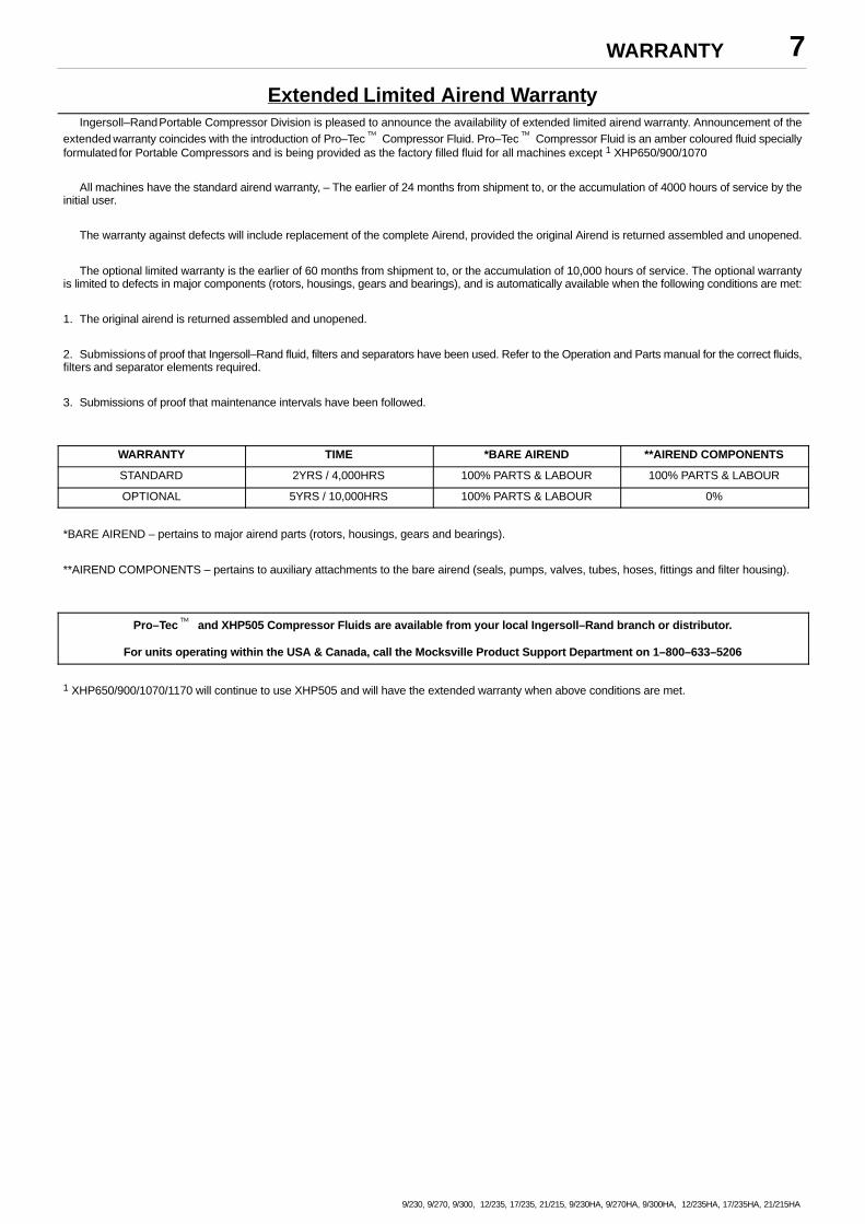
Extended Limited Airend WarrantyIngersoll–Rand Portable Compressor Division is pleased to announce the availability of extended limited airend warranty. Announcement of the
extended warranty coincides with the introduction of Pro–Tec� Compressor Fluid. Pro–Tec� Compressor Fluid is an amber coloured fluid speciallyformulated for Portable Compressors and is being provided as the factory filled fluid for all machines except 1 XHP650/900/1070
All machines have the standard airend warranty, – The earlier of 24 months from shipment to, or the accumulation of 4000 hours of service by theinitial user.
The warranty against defects will include replacement of the complete Airend, provided the original Airend is returned assembled and unopened.
The optional limited warranty is the earlier of 60 months from shipment to, or the accumulation of 10,000 hours of service. The optional warrantyis limited to defects in major components (rotors, housings, gears and bearings), and is automatically available when the following conditions are met:
1. The original airend is returned assembled and unopened.
2. Submissions of proof that Ingersoll–Rand fluid, filters and separators have been used. Refer to the Operation and Parts manual for the correct fluids,filters and separator elements required.
3. Submissions of proof that maintenance intervals have been followed.
WARRANTY TIME *BARE AIREND **AIREND COMPONENTS
STANDARD 2YRS / 4,000HRS 100% PARTS & LABOUR 100% PARTS & LABOUR
OPTIONAL 5YRS / 10,000HRS 100% PARTS & LABOUR 0%
*BARE AIREND – pertains to major airend parts (rotors, housings, gears and bearings).
**AIREND COMPONENTS – pertains to auxiliary attachments to the bare airend (seals, pumps, valves, tubes, hoses, fittings and filter housing).
Pro–Tec� and XHP505 Compressor Fluids are available from your local Ingersoll–Rand branch or distributor.
For units operating within the USA & Canada, call the Mocksville Product Support Department on 1–800–633–5206
1 XHP650/900/1070/1170 will continue to use XHP505 and will have the extended warranty when above conditions are met.
WARRANTY8
9/230, 9/270, 9/300, 12/235, 17/235, 21/215, 9/230HA, 9/270HA, 9/300HA, 12/235HA, 17/235HA, 21/215HA
WARRANTY REGISTRATION
FOR UNITS SOURCED FROM HORWICH, UK
Complete Machine Registration
To initiate the machine warranty, fill out the ”Warranty Registration” form 85040285 supplied as part of the machine documentation, keep a copy foryour records and mail the original to:
Ingersoll Rand European Sales LtdPortable Power BusinessSwan LaneHindley GreenWiganLancashireWN2 4EZ
U.K.
Attn: Customer Service Department
Note: Completion of this form validates the warranty.
Engine Registration:I–R powered machines do not require separate engine registration.
Deutz require a separate engine registration form to be completed and mailed direct to their Cologne office. The form is supplied as part of the machinedocumentation for Deutz powered machines.
Caterpillar, Cummins and Perkins do not require a separate registration form but they stipulate that any new engine should be registered with their localdealer to initiate warranty.
You MUST provide proof of the “in–service” date when requesting engine warranty repairs.
WARRANTY 9
9/230, 9/270, 9/300, 12/235, 17/235, 21/215, 9/230HA, 9/270HA, 9/300HA, 12/235HA, 17/235HA, 21/215HA
WARRANTY REGISTRATION
FOR UNITS SOURCED FROM MOCKSVILLE, USA
Complete Machine Registration
Machines shipped to locations within the United States do not require a warranty registration unless the machine status changes (i.e. change of
ownership).
Machines shipped outside the United States require notification be made to initiate the machine warranty.
Fill out the Warranty Registration Form in this section, keep a copy for your records andmail form to:
Ingersoll–Rand CompanyP.O. Box 868
Mocksville, North Carolina 27028
Attn: Warranty Department
Note: Completion of this form validates the warranty.
Engine Registration:I–R powered machines do not require separate engine registration.
John Deere requires a separate engine registration be completed and mailed direct to John Deere.
Separate engine registration material is included with this literature package for John Deere powered machines.
All other engine manufacturers do not require a separate engine registration.
You MUST present proof of in–service date at time of requesting engine warranty service.
SAMPLE
WARRANTY10
9/230, 9/270, 9/300, 12/235, 17/235, 21/215, 9/230HA, 9/270HA, 9/300HA, 12/235HA, 17/235HA, 21/215HA
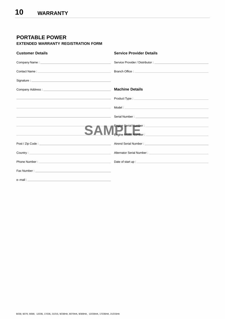
PORTABLE POWEREXTENDED WARRANTY REGISTRATION FORM
Customer Details Service Provider Details
Company Name : Service Provider / Distributor :
Contact Name : Branch Office :
Signature :
Company Address : Machine Details
Product Type :
Model :
Serial Number :
Engine Serial Number :
Engine Model Number :
Post / Zip Code : Airend Serial Number :
Country : Alternator Serial Number :
Phone Number : Date of start up :
Fax Number :
e–mail :
ISO SYMBOLS 11
9/230, 9/270, 9/300, 12/235, 17/235, 21/215, 9/230HA, 9/270HA, 9/300HA, 12/235HA, 17/235HA, 21/215HA
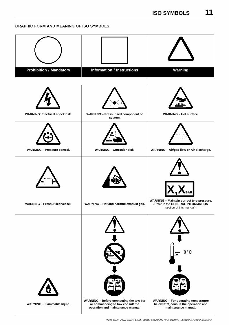
GRAPHIC FORM AND MEANING OF ISO SYMBOLS
Prohibition / Mandatory Information / Instructions Warning
WARNING: Electrical shock risk. WARNING – Pressurised component orsystem.
WARNING – Hot surface.
WARNING – Pressure control. WARNING – Corrosion risk. WARNING – Air/gas flow or Air discharge.
X,XBAR
WARNING – Pressurised vessel. WARNING – Hot and harmful exhaust gas.WARNING – Maintain correct tyre pressure.
(Refer to the GENERAL INFORMATIONsection of this manual).
0�C
WARNING – Flammable liquid.WARNING – Before connecting the tow bar
or commencing to tow consult theoperation and maintenance manual.
WARNING – For operating temperaturebelow 0�C, consult the operation and
maintenance manual.
ISO SYMBOLS12
9/230, 9/270, 9/300, 12/235, 17/235, 21/215, 9/230HA, 9/270HA, 9/300HA, 12/235HA, 17/235HA, 21/215HA
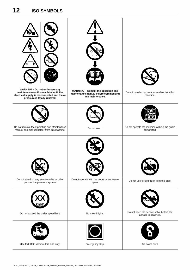
WARNING – Do not undertake anymaintenance on this machine until the
electrical supply is disconnected and the airpressure is totally relieved.
WARNING – Consult the operation andmaintenance manual before commencing
any maintenance.
Do not breathe the compressed air from thismachine.
Do not remove the Operating and Maintenancemanual and manual holder from this machine. Do not stack. Do not operate the machine without the guard
being fitted.
Do not stand on any service valve or otherparts of the pressure system.
Do not operate with the doors or enclosureopen. Do not use fork lift truck from this side.
XXkm/h
Do not exceed the trailer speed limit. No naked lights. Do not open the service valve before theairhose is attached.
Use fork lift truck from this side only. Emergency stop. Tie down point
ISO SYMBOLS 13
9/230, 9/270, 9/300, 12/235, 17/235, 21/215, 9/230HA, 9/270HA, 9/300HA, 12/235HA, 17/235HA, 21/215HA
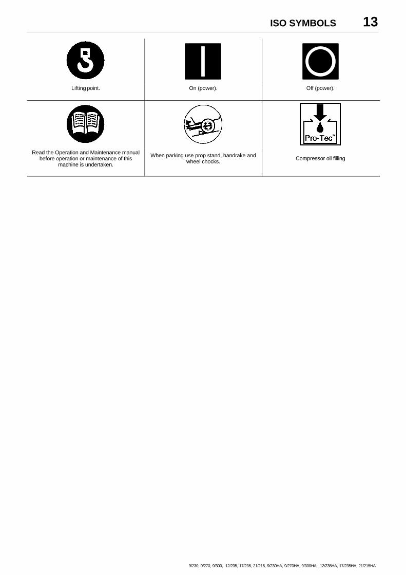
Lifting point. On (power). Off (power).
Read the Operation and Maintenance manualbefore operation or maintenance of this
machine is undertaken.
When parking use prop stand, handrake andwheel chocks. Compressor oil filling
SAFETY 14
9/230, 9/270, 9/300, 12/235, 17/235, 21/215, 9/230HA, 9/270HA, 9/300HA, 12/235HA, 17/235HA, 21/215HA
WARNINGSWarnings call attention to instructions which must be followed
precisely to avoid injury or death.
CAUTIONSCautions call attention to instructions which must be followed
precisely to avoid damaging the product, process or its surroundings.
NOTESNotes are used for supplementary information.
General Information
Ensure that the operator reads and understands the decals andconsults the manuals before maintenance or operation.
Ensure that the Operation and Maintenance manual, and themanual holder, are not removed permanently from the machine.
Ensure that maintenance personnel are adequately trained,competent and have read the Maintenance Manuals.
Make sure that all protective covers are in place and that thecanopy/doors are closed during operation.
The specification of this machine is such that the machine is notsuitable for use in flammable gas risk areas. If such an application isrequired then all local regulations, codes of practice and site rules mustbe observed. To ensure that the machine can operate in a safe andreliable manner, additional equipment such as gas detection, exhaustspark arrestors, and intake (shut–off) valves may be required,dependant on local regulations or the degree of risk involved.
A weekly visual check must be made on all fasteners/fixing screwssecuring mechanical parts. In particular, safety–related parts such ascoupling hitch, drawbar components, road–wheels, and lifting bail
should be checked for total security.
All components which are loose, damaged or unserviceable, must
be rectified without delay.
Compressed air
Compressed air can be dangerous if incorrectly handled. Beforedoing any work on the unit, ensure that all pressure is vented from thesystem and that the machine cannot be started accidentally.
Ensure that the machine is operating at the rated pressure and thatthe rated pressure is known to all relevant personnel.
All air pressure equipment installed in or connected to the machinemust have safe working pressure ratings of at least the machine ratedpressure.
If more than one compressor is connected to one commondownstream plant, effective check valves and isolation valves must befitted and controlled by work procedures, so that one machine cannotaccidently be pressurised / over pressurised by another.
Compressed air must not be used for a direct feed to any form ofbreathing apparatus or mask.
The discharged air contains a very small percentage of compressorlubricating oil and care should be taken to ensure that downstreamequipment is compatible.
If the discharged air is to be ultimately released into a confinedspace, adequate ventilation must be provided.
When using compressed air always use appropriate personalprotective equipment.
All pressure containing parts, especially flexible hoses and theircouplings, must be regularly inspected, be free from defects and bereplaced according to the Manual instructions.
Avoid bodily contact with compressed air.
The safety valve located in the separator tank must be checkedperiodically for correct operation.
Materials
The following substances may be produced during the operation ofthis machine:. brake lining dust. engine exhaust fumes
AVOID INHALATION
Ensure that adequate ventilation of the cooling system and exhaustgases is maintained at all times.
The following substances are used in the manufacture of thismachine and may be hazardous to health if used incorrectly:
. anti–freeze
. compressor lubricant
. engine lubricant
. preservative grease
. rust preventative
. diesel fuel
. battery electrolyte
AVOID INGESTION, SKIN CONTACT AND INHALATION OFFUMES
Should compressor lubricant come into contact with the eyes, thenirrigate with water for at least 5 minutes.
Should compressor lubricant come into contact with the skin, thenwash off immediately.
Consult a physician if large amounts of compressor lubricant areingested.
Consult a physician if compressor lubricant is inhaled.
Never give fluids or induce vomiting if the patient is unconscious orhaving convulsions.
Safety data sheets for compressor and engine lubricants should beobtained from the lubricant supplier.
Battery
Batteries contain corrosive liquid and produce explosive gas. Donot expose to naked lights. Always wear personal protective clothingwhen handling. When starting the machine from a slave battery ensurethat the correct polarity is observed and that connections are secure.
DO NOT ATTEMPT TO SLAVE START A FROZEN BATTERYSINCE THIS MAY CAUSE IT TO EXPLODE.
Radiator
Hot engine coolant and steam can cause injury. Ensure that theradiator filler cap is removed with due care and attention.
Engine starting fluid (ether)
Use and recharge system only with suppliers instructions andreplacement parts.
Some machines are fitted with an ether cold starting aid.
SAFETY 15
9/230, 9/270, 9/300, 12/235, 17/235, 21/215, 9/230HA, 9/270HA, 9/300HA, 12/235HA, 17/235HA, 21/215HA
Do NOT use on engines which are provided with inlet heaters.
AVOID INGESTION, INHALATION, HOT SURFACES AND NAKEDLIGHTS
Transport
When loading or transporting machines ensure that the specifiedlifting and tie down points are used.
When loading or transporting machines ensure that the towingvehicle, its size, weight, towing hitch and electrical supply are allsuitable to provide safe and stable towing at speeds either, up to thelegal maximum for the country in which it is being towed or, as specifiedfor the machine model if lower than the legal maximum.
Before towing the machine, ensure that:–
. the tyres and towing hitch are in a serviceable condition.
. the canopy is secure.
. all ancillary equipment is stored in a safe and secure manner.
When parking always use the handbrake and, if necessary, suitablewheel chocks.
GENERAL INFORMATION – ESA (CE/HA)16
9/230, 9/270, 9/300, 12/235, 17/235, 21/215, 9/230HA, 9/270HA, 9/300HA, 12/235HA, 17/235HA, 21/215HA
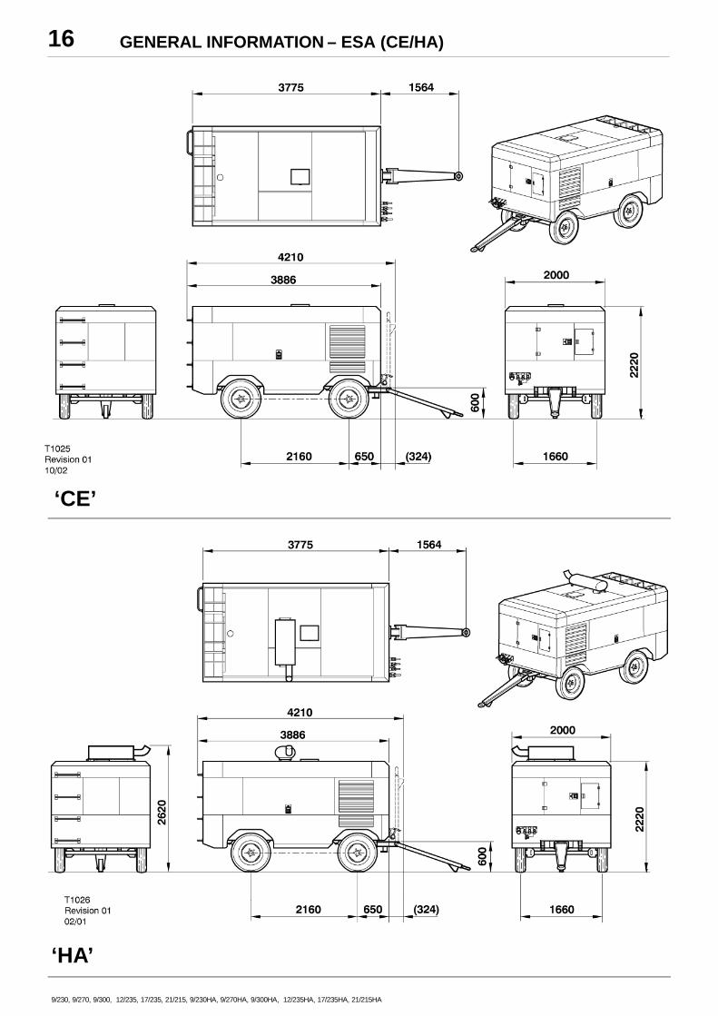
‘CE’
‘HA’
GENERAL INFORMATION – ESA (CE/HA) 17
9/230, 9/270, 9/300, 12/235, 17/235, 21/215, 9/230HA, 9/270HA, 9/300HA, 12/235HA, 17/235HA, 21/215HA
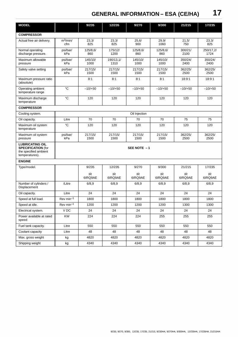
MODEL 9/235 12/235 9/270 9/300 21/215 17/235
COMPRESSOR
Actual free air delivery. m3/min/cfm
23,3/825
23,3/825
25,6/900
29,9/1060
21,5/750
23,3/825
Normal operatingdischarge pressure.
psi/bar/kPa
125/8,6/860
175/12/1200
125/8,6/860
125/8,6/860
300/21/2100
250/17,2/1724
Maximum allowablepressure
psi/bar/kPa
145/10/1000
190/13,1/1310
145/10/1000
145/10/1000
350/24/2400
350/24/2400
Safety valve setting psi/bar/kPa
217/15/1500
217/15/1500
217/15/1500
217/15/1500
362/25/2500
362/25/2500
Maximum pressure ratio(absolute)
8:1 8:1 8:1 8:1 18:9:1 18:9:1
Operating ambienttemperature range
°C –10/+50 –10/+50 –10/+50 –10/+50 –10/+50 –10/+50
Maximum dischargetemperature
°C 120 120 120 120 120 120
COMPRESSOR
Cooling system. Oil Injection
Oil capacity. Litre 70 70 70 70 75 75
Maximum oil systemtemperature
°C 120 120 120 120 120 120
Maximum oil systempressure
psi/bar/kPa
217/15/1500
217/15/1500
217/15/1500
217/15/1500
362/25/2500
362/25/2500
LUBRICATING OILSPECIFICATION (for SEE NOTE – 1the specified ambienttemperatures).
ENGINE
Type/model. 9/235
IR6IRQ9AE
12/235
IR6IRQ9AE
9/270
IR6IRQ9AE
9/300
IR6IRQ9AE
21/215
IR6IRQ9AE
17/235
IR6IRQ9AE
Number of cylinders /Displacement
/Litre 6/8,9 6/8,9 6/8,9 6/8,9 6/8,9 6/8,9
Oil capacity. Litre 24 24 24 24 24 24
Speed at full load. Rev min–1 1800 1800 1800 1800 1800 1800
Speed at idle. Rev min–1 1200 1200 1200 1200 1300 1300
Electrical system. V DC 24 24 24 24 24 24
Power available at ratedspeed
KW 224 224 224 255 255 255
Fuel tank capacity. Litre 550 550 550 550 550 550
Coolant capacity Litre 48 48 48 48 48 48
Max. gross weight kg 4820 4820 4820 4820 4820 4820
Shipping weight kg 4340 4340 4340 4340 4340 4340
GENERAL INFORMATION – ESA (CE/HA)18
9/230, 9/270, 9/300, 12/235, 17/235, 21/215, 9/230HA, 9/270HA, 9/300HA, 12/235HA, 17/235HA, 21/215HA
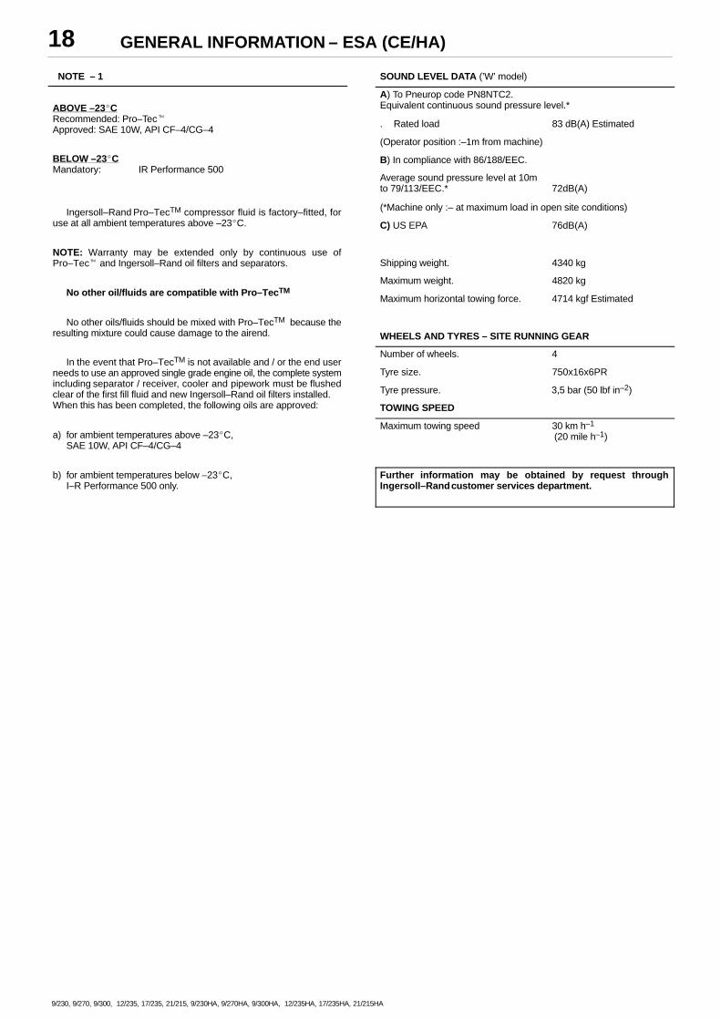
NOTE – 1
ABOVE –23�CRecommended: Pro–Tec�Approved: SAE 10W, API CF–4/CG–4
BELOW –23�CMandatory: IR Performance 500
Ingersoll–Rand Pro–TecTM compressor fluid is factory–fitted, foruse at all ambient temperatures above –23�C.
NOTE: Warranty may be extended only by continuous use ofPro–Tec� and Ingersoll–Rand oil filters and separators.
No other oil/fluids are compatible with Pro–TecTM
No other oils/fluids should be mixed with Pro–TecTM because theresulting mixture could cause damage to the airend.
In the event that Pro–TecTM is not available and / or the end userneeds to use an approved single grade engine oil, the complete systemincluding separator / receiver, cooler and pipework must be flushedclear of the first fill fluid and new Ingersoll–Rand oil filters installed.When this has been completed, the following oils are approved:
a) for ambient temperatures above –23�C,SAE 10W, API CF–4/CG–4
b) for ambient temperatures below –23�C,I–R Performance 500 only.
SOUND LEVEL DATA (’W’ model)
A) To Pneurop code PN8NTC2.Equivalent continuous sound pressure level.*
. Rated load 83 dB(A) Estimated
(Operator position :–1m from machine)
B) In compliance with 86/188/EEC.
Average sound pressure level at 10m to 79/113/EEC.* 72dB(A)
(*Machine only :– at maximum load in open site conditions)
C) US EPA 76dB(A)
Shipping weight. 4340 kg
Maximum weight. 4820 kg
Maximum horizontal towing force. 4714 kgf Estimated
WHEELS AND TYRES – SITE RUNNING GEAR
Number of wheels. 4
Tyre size. 750x16x6PR
Tyre pressure. 3,5 bar (50 lbf in–2)
TOWING SPEED
Maximum towing speed 30 km h–1
(20 mile h–1)
Further information may be obtained by request throughIngersoll–Rand customer services department.
OPERATING INSTRUCTIONS 19
9/230, 9/270, 9/300, 12/235, 17/235, 21/215, 9/230HA, 9/270HA, 9/300HA, 12/235HA, 17/235HA, 21/215HA
COMMISSIONING
Upon receipt of the unit, and prior to putting it into service, it isimportant to adhere strictly to the instructions given below in PRIOR TOSTARTING.
Ensure that the operator reads and understands the decals andconsults the manuals before maintenance or operation.
Ensure that the position of the emergency stop device is known andrecognised by its markings. Ensure that it is functioning correctly andthat the method of operation is known.
Before towing the unit, ensure that the tyre pressures are correct(refer to the GENERAL INFORMATION section of this manual) andthat the handbrake is functioning correctly (refer to theMAINTENANCE section of this manual). Before towing the unit duringthe hours of darkness, ensure that the lights are functioning correctly(where fitted).
Ensure that all transport and packing materials are discarded.
Ensure that the correct fork lift truck slots or marked lifting / tie downpoints are used whenever the machine is lifted or transported.
When selecting the working position of the machine ensure thatthere is sufficient clearance for ventilation and exhaust requirements,observing any specified minimum dimensions (to walls, floors etc.).
Adequate clearance needs to be allowed around and above themachine to permit safe access for specified maintenance tasks.
Ensure that the machine is positioned securely and on a stablefoundation. Any risk of movement should be removed by suitablemeans, especially to avoid strain on any rigid discharge piping.
Attach the battery cables to the battery(s) ensuring that they aretightened securely. Attach the negative cable bofore attaching thepositive cable
WARNING: All air pressure equipment installed in or connectedto the machine must have safe working pressure ratings of at leastthe machine rated pressure, and materials compatible with thecompressor lubricant (refer to the GENERAL INFORMATIONsection).
WARNING: If more than one compressor is connected to onecommon downstream plant, effective check valves and isolationvalves must be fitted and controlled by work procedures, so thatone machine cannot accidently be pressurised / over pressurisedby another.
WARNING: If flexible discharge hoses are to carry more than 7 barpressure then it is recommended that safety retaining wires areused on the hoses.
OPERATING INSTRUCTIONS20
9/230, 9/270, 9/300, 12/235, 17/235, 21/215, 9/230HA, 9/270HA, 9/300HA, 12/235HA, 17/235HA, 21/215HA
PRIOR TO STARTING
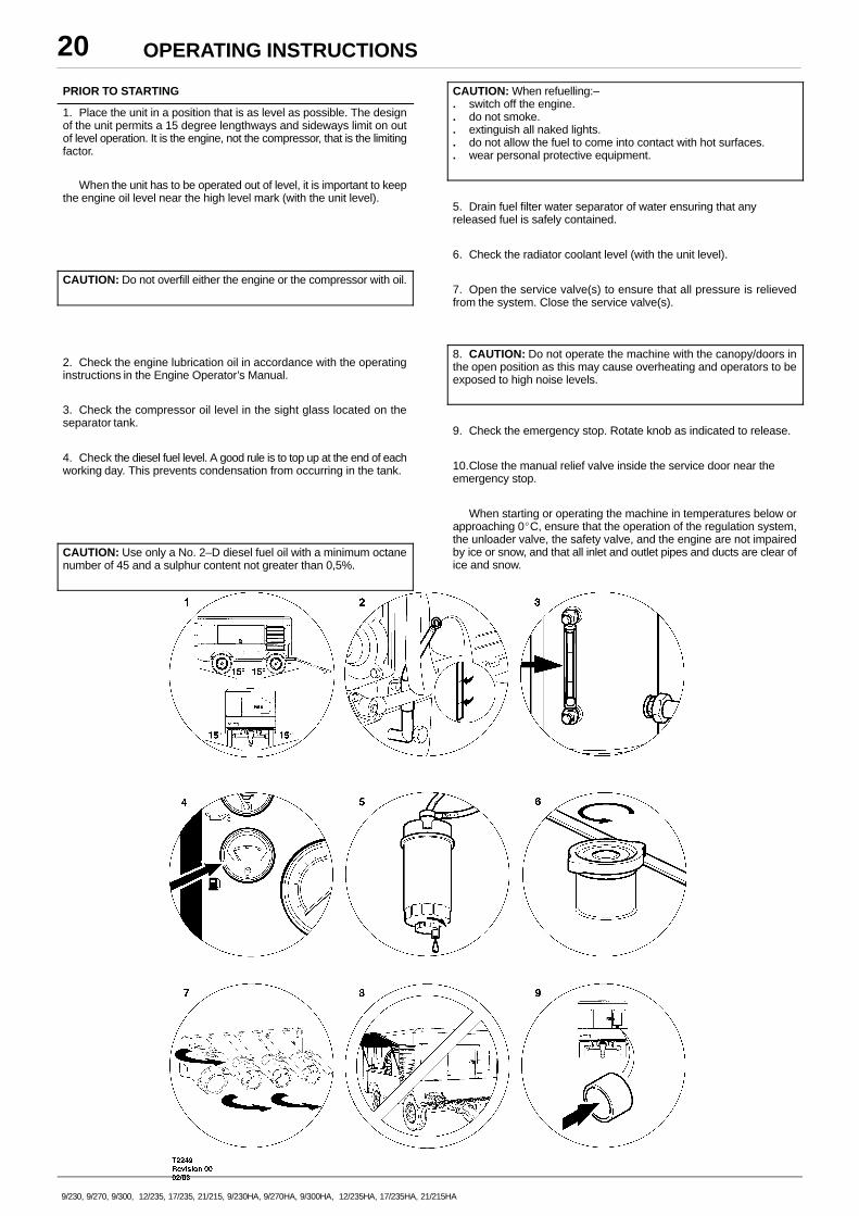
1. Place the unit in a position that is as level as possible. The designof the unit permits a 15 degree lengthways and sideways limit on outof level operation. It is the engine, not the compressor, that is the limitingfactor.
When the unit has to be operated out of level, it is important to keepthe engine oil level near the high level mark (with the unit level).
CAUTION: Do not overfill either the engine or the compressor with oil.
2. Check the engine lubrication oil in accordance with the operatinginstructions in the Engine Operator’s Manual.
3. Check the compressor oil level in the sight glass located on theseparator tank.
4. Check the diesel fuel level. A good rule is to top up at the end of eachworking day. This prevents condensation from occurring in the tank.
CAUTION: Use only a No. 2–D diesel fuel oil with a minimum octanenumber of 45 and a sulphur content not greater than 0,5%.
CAUTION: When refuelling:–. switch off the engine.. do not smoke.. extinguish all naked lights.. do not allow the fuel to come into contact with hot surfaces.. wear personal protective equipment.
5. Drain fuel filter water separator of water ensuring that anyreleased fuel is safely contained.
6. Check the radiator coolant level (with the unit level).
7. Open the service valve(s) to ensure that all pressure is relievedfrom the system. Close the service valve(s).
8. CAUTION: Do not operate the machine with the canopy/doors inthe open position as this may cause overheating and operators to beexposed to high noise levels.
9. Check the emergency stop. Rotate knob as indicated to release.
10.Close the manual relief valve inside the service door near theemergency stop.
When starting or operating the machine in temperatures below orapproaching 0�C, ensure that the operation of the regulation system,the unloader valve, the safety valve, and the engine are not impairedby ice or snow, and that all inlet and outlet pipes and ducts are clear ofice and snow.
OPERATING INSTRUCTIONS 21
9/230, 9/270, 9/300, 12/235, 17/235, 21/215, 9/230HA, 9/270HA, 9/300HA, 12/235HA, 17/235HA, 21/215HA
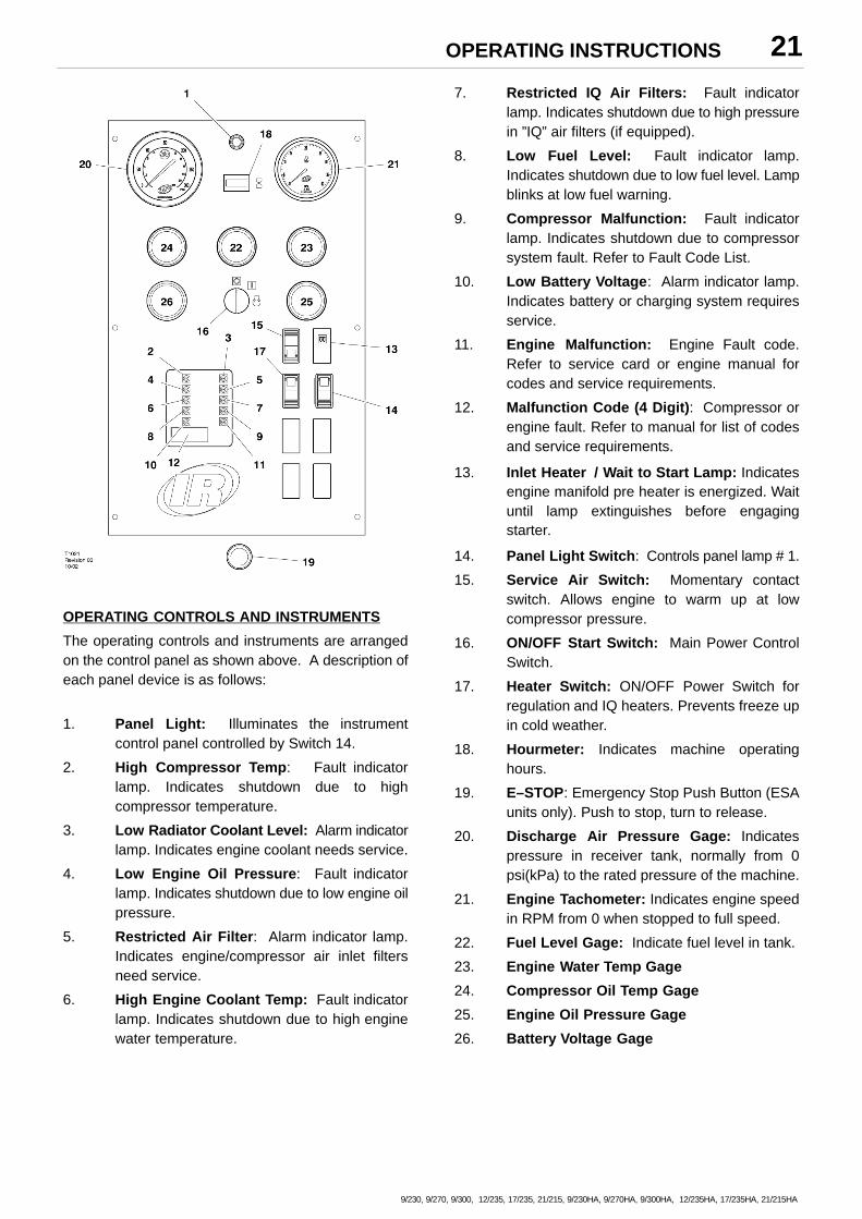
OPERATING CONTROLS AND INSTRUMENTS
The operating controls and instruments are arrangedon the control panel as shown above. A description ofeach panel device is as follows:
1. Panel Light: Illuminates the instrumentcontrol panel controlled by Switch 14.
2. High Compressor Temp: Fault indicatorlamp. Indicates shutdown due to highcompressor temperature.
3. Low Radiator Coolant Level: Alarm indicatorlamp. Indicates engine coolant needs service.
4. Low Engine Oil Pressure: Fault indicatorlamp. Indicates shutdown due to low engine oilpressure.
5. Restricted Air Filter: Alarm indicator lamp.Indicates engine/compressor air inlet filtersneed service.
6. High Engine Coolant Temp: Fault indicatorlamp. Indicates shutdown due to high enginewater temperature.
7. Restricted IQ Air Filters: Fault indicatorlamp. Indicates shutdown due to high pressurein ”IQ” air filters (if equipped).
8. Low Fuel Level: Fault indicator lamp.Indicates shutdown due to low fuel level. Lampblinks at low fuel warning.
9. Compressor Malfunction: Fault indicatorlamp. Indicates shutdown due to compressorsystem fault. Refer to Fault Code List.
10. Low Battery Voltage: Alarm indicator lamp.Indicates battery or charging system requiresservice.
11. Engine Malfunction: Engine Fault code.Refer to service card or engine manual forcodes and service requirements.
12. Malfunction Code (4 Digit): Compressor orengine fault. Refer to manual for list of codesand service requirements.
13. Inlet Heater / Wait to Start Lamp: Indicatesengine manifold pre heater is energized. Waituntil lamp extinguishes before engagingstarter.
14. Panel Light Switch: Controls panel lamp # 1.
15. Service Air Switch: Momentary contactswitch. Allows engine to warm up at lowcompressor pressure.
16. ON/OFF Start Switch: Main Power ControlSwitch.
17. Heater Switch: ON/OFF Power Switch forregulation and IQ heaters. Prevents freeze upin cold weather.
18. Hourmeter: Indicates machine operatinghours.
19. E–STOP: Emergency Stop Push Button (ESAunits only). Push to stop, turn to release.
20. Discharge Air Pressure Gage: Indicatespressure in receiver tank, normally from 0psi(kPa) to the rated pressure of the machine.
21. Engine Tachometer: Indicates engine speedin RPM from 0 when stopped to full speed.
22. Fuel Level Gage: Indicate fuel level in tank.
23. Engine Water Temp Gage
24. Compressor Oil Temp Gage
25. Engine Oil Pressure Gage
26. Battery Voltage Gage
OPERATING INSTRUCTIONS22
9/230, 9/270, 9/300, 12/235, 17/235, 21/215, 9/230HA, 9/270HA, 9/300HA, 12/235HA, 17/235HA, 21/215HA
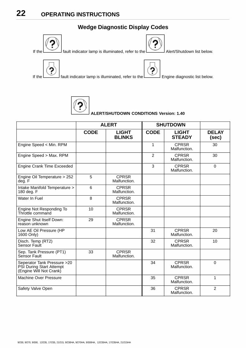
Wedge Diagnostic Display Codes
If the fault indicator lamp is illuminated, refer to the Alert/Shutdown list below.
If the fault indicator lamp is illuminated, refer to the Engine diagnostic list below.
ALERT/SHUTDOWN CONDITIONS Version: 1.40
ALERT SHUTDOWN
CODE LIGHTBLINKS
CODE LIGHTSTEADY
DELAY (sec)
Engine Speed < Min. RPM 1 CPRSRMalfunction.
30
Engine Speed > Max. RPM 2 CPRSRMalfunction.
30
Engine Crank Time Exceeded 3 CPRSRMalfunction.
0
Engine Oil Temperature > 252deg. F
5 CPRSRMalfunction.
Intake Manifold Temperature >180 deg. F
6 CPRSRMalfunction.
Water In Fuel 8 CPRSRMalfunction.
Engine Not Responding ToThrottle command
10 CPRSRMalfunction.
Engine Shut Itself Down:reason unknown
29 CPRSRMalfunction.
Low AE Oil Pressure (HP1600 Only)
31 CPRSRMalfunction.
20
Disch. Temp (RT2)Sensor Fault
32 CPRSRMalfunction.
10
Sep. Tank Pressure (PT1)Sensor Fault
33 CPRSRMalfunction.
Seperator Tank Pressure >20PSI During Start Attempt(Engine Will Not Crank)
34 CPRSRMalfunction.
0
Machine Over Pressure 35 CPRSRMalfunction.
1
Safety Valve Open 36 CPRSRMalfunction.
2
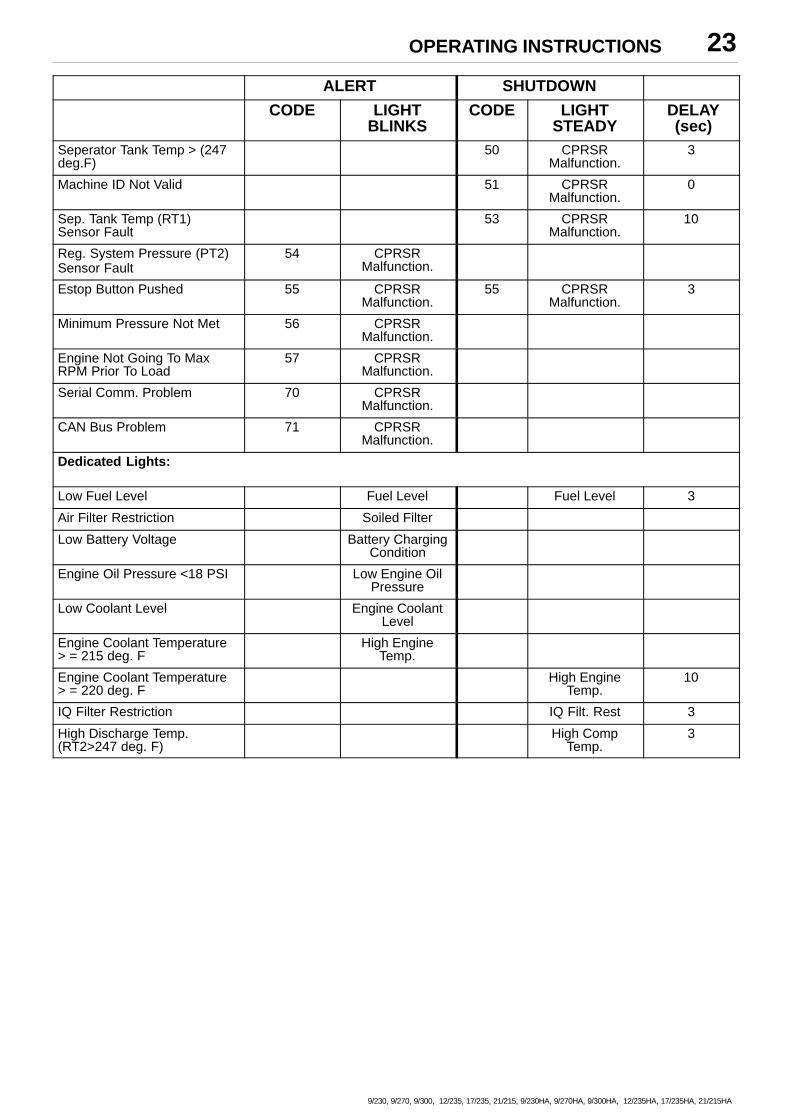
OPERATING INSTRUCTIONS 23
9/230, 9/270, 9/300, 12/235, 17/235, 21/215, 9/230HA, 9/270HA, 9/300HA, 12/235HA, 17/235HA, 21/215HA
ALERT SHUTDOWN
CODE LIGHTBLINKS
CODE LIGHTSTEADY
DELAY (sec)
Seperator Tank Temp > (247deg.F)
50 CPRSRMalfunction.
3
Machine ID Not Valid 51 CPRSRMalfunction.
0
Sep. Tank Temp (RT1)Sensor Fault
53 CPRSRMalfunction.
10
Reg. System Pressure (PT2)Sensor Fault
54 CPRSRMalfunction.
Estop Button Pushed 55 CPRSRMalfunction.
55 CPRSRMalfunction.
3
Minimum Pressure Not Met 56 CPRSRMalfunction.
Engine Not Going To MaxRPM Prior To Load
57 CPRSRMalfunction.
Serial Comm. Problem 70 CPRSRMalfunction.
CAN Bus Problem 71 CPRSRMalfunction.
Dedicated Lights:
Low Fuel Level Fuel Level Fuel Level 3
Air Filter Restriction Soiled Filter
Low Battery Voltage Battery ChargingCondition
Engine Oil Pressure <18 PSI Low Engine OilPressure
Low Coolant Level Engine CoolantLevel
Engine Coolant Temperature > = 215 deg. F
High EngineTemp.
Engine Coolant Temperature > = 220 deg. F
High EngineTemp.
10
IQ Filter Restriction IQ Filt. Rest 3
High Discharge Temp.(RT2>247 deg. F)
High CompTemp.
3
OPERATING INSTRUCTIONS24
9/230, 9/270, 9/300, 12/235, 17/235, 21/215, 9/230HA, 9/270HA, 9/300HA, 12/235HA, 17/235HA, 21/215HA
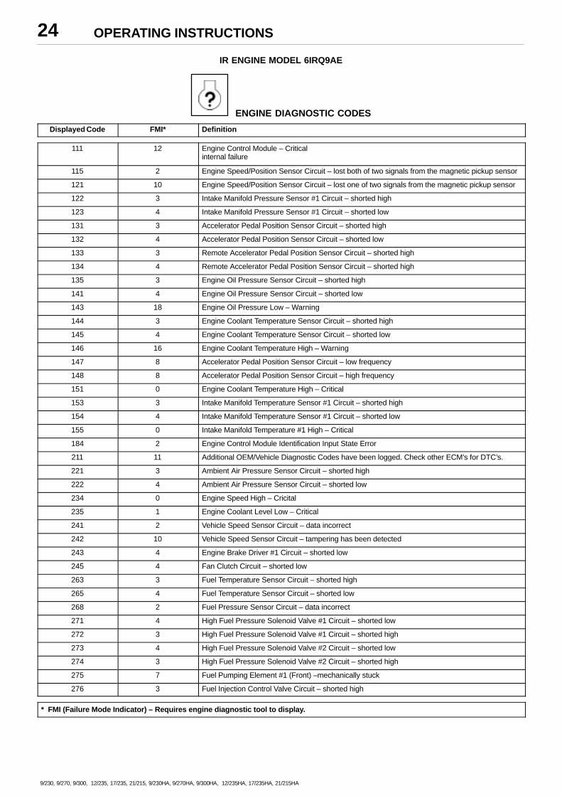
IR ENGINE MODEL 6IRQ9AE
ENGINE DIAGNOSTIC CODES
Displayed Code FMI* Definition
111 12 Engine Control Module – Criticalinternal failure
115 2 Engine Speed/Position Sensor Circuit – lost both of two signals from the magnetic pickup sensor
121 10 Engine Speed/Position Sensor Circuit – lost one of two signals from the magnetic pickup sensor
122 3 Intake Manifold Pressure Sensor #1 Circuit – shorted high
123 4 Intake Manifold Pressure Sensor #1 Circuit – shorted low
131 3 Accelerator Pedal Position Sensor Circuit – shorted high
132 4 Accelerator Pedal Position Sensor Circuit – shorted low
133 3 Remote Accelerator Pedal Position Sensor Circuit – shorted high
134 4 Remote Accelerator Pedal Position Sensor Circuit – shorted high
135 3 Engine Oil Pressure Sensor Circuit – shorted high
141 4 Engine Oil Pressure Sensor Circuit – shorted low
143 18 Engine Oil Pressure Low – Warning
144 3 Engine Coolant Temperature Sensor Circuit – shorted high
145 4 Engine Coolant Temperature Sensor Circuit – shorted low
146 16 Engine Coolant Temperature High – Warning
147 8 Accelerator Pedal Position Sensor Circuit – low frequency
148 8 Accelerator Pedal Position Sensor Circuit – high frequency
151 0 Engine Coolant Temperature High – Critical
153 3 Intake Manifold Temperature Sensor #1 Circuit – shorted high
154 4 Intake Manifold Temperature Sensor #1 Circuit – shorted low
155 0 Intake Manifold Temperature #1 High – Critical
184 2 Engine Control Module Identification Input State Error
211 11 Additional OEM/Vehicle Diagnostic Codes have been logged. Check other ECM’s for DTC’s.
221 3 Ambient Air Pressure Sensor Circuit – shorted high
222 4 Ambient Air Pressure Sensor Circuit – shorted low
234 0 Engine Speed High – Cricital
235 1 Engine Coolant Level Low – Critical
241 2 Vehicle Speed Sensor Circuit – data incorrect
242 10 Vehicle Speed Sensor Circuit – tampering has been detected
243 4 Engine Brake Driver #1 Circuit – shorted low
245 4 Fan Clutch Circuit – shorted low
263 3 Fuel Temperature Sensor Circuit – shorted high
265 4 Fuel Temperature Sensor Circuit – shorted low
268 2 Fuel Pressure Sensor Circuit – data incorrect
271 4 High Fuel Pressure Solenoid Valve #1 Circuit – shorted low
272 3 High Fuel Pressure Solenoid Valve #1 Circuit – shorted high
273 4 High Fuel Pressure Solenoid Valve #2 Circuit – shorted low
274 3 High Fuel Pressure Solenoid Valve #2 Circuit – shorted high
275 7 Fuel Pumping Element #1 (Front) –mechanically stuck
276 3 Fuel Injection Control Valve Circuit – shorted high
* FMI (Failure Mode Indicator) – Requires engine diagnostic tool to display.
OPERATING INSTRUCTIONS 25
9/230, 9/270, 9/300, 12/235, 17/235, 21/215, 9/230HA, 9/270HA, 9/300HA, 12/235HA, 17/235HA, 21/215HA
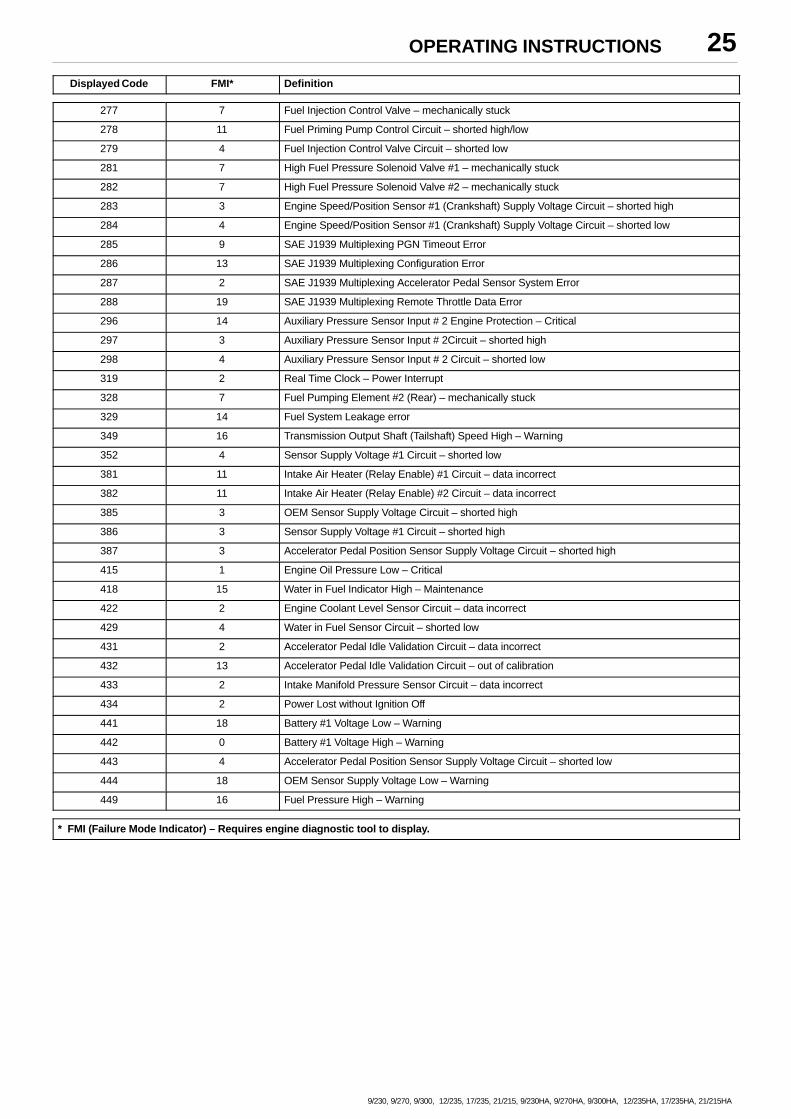
Displayed Code FMI* Definition
277 7 Fuel Injection Control Valve – mechanically stuck
278 11 Fuel Priming Pump Control Circuit – shorted high/low
279 4 Fuel Injection Control Valve Circuit – shorted low
281 7 High Fuel Pressure Solenoid Valve #1 – mechanically stuck
282 7 High Fuel Pressure Solenoid Valve #2 – mechanically stuck
283 3 Engine Speed/Position Sensor #1 (Crankshaft) Supply Voltage Circuit – shorted high
284 4 Engine Speed/Position Sensor #1 (Crankshaft) Supply Voltage Circuit – shorted low
285 9 SAE J1939 Multiplexing PGN Timeout Error
286 13 SAE J1939 Multiplexing Configuration Error
287 2 SAE J1939 Multiplexing Accelerator Pedal Sensor System Error
288 19 SAE J1939 Multiplexing Remote Throttle Data Error
296 14 Auxiliary Pressure Sensor Input # 2 Engine Protection – Critical
297 3 Auxiliary Pressure Sensor Input # 2Circuit – shorted high
298 4 Auxiliary Pressure Sensor Input # 2 Circuit – shorted low
319 2 Real Time Clock – Power Interrupt
328 7 Fuel Pumping Element #2 (Rear) – mechanically stuck
329 14 Fuel System Leakage error
349 16 Transmission Output Shaft (Tailshaft) Speed High – Warning
352 4 Sensor Supply Voltage #1 Circuit – shorted low
381 11 Intake Air Heater (Relay Enable) #1 Circuit – data incorrect
382 11 Intake Air Heater (Relay Enable) #2 Circuit – data incorrect
385 3 OEM Sensor Supply Voltage Circuit – shorted high
386 3 Sensor Supply Voltage #1 Circuit – shorted high
387 3 Accelerator Pedal Position Sensor Supply Voltage Circuit – shorted high
415 1 Engine Oil Pressure Low – Critical
418 15 Water in Fuel Indicator High – Maintenance
422 2 Engine Coolant Level Sensor Circuit – data incorrect
429 4 Water in Fuel Sensor Circuit – shorted low
431 2 Accelerator Pedal Idle Validation Circuit – data incorrect
432 13 Accelerator Pedal Idle Validation Circuit – out of calibration
433 2 Intake Manifold Pressure Sensor Circuit – data incorrect
434 2 Power Lost without Ignition Off
441 18 Battery #1 Voltage Low – Warning
442 0 Battery #1 Voltage High – Warning
443 4 Accelerator Pedal Position Sensor Supply Voltage Circuit – shorted low
444 18 OEM Sensor Supply Voltage Low – Warning
449 16 Fuel Pressure High – Warning
* FMI (Failure Mode Indicator) – Requires engine diagnostic tool to display.
OPERATING INSTRUCTIONS26
9/230, 9/270, 9/300, 12/235, 17/235, 21/215, 9/230HA, 9/270HA, 9/300HA, 12/235HA, 17/235HA, 21/215HA
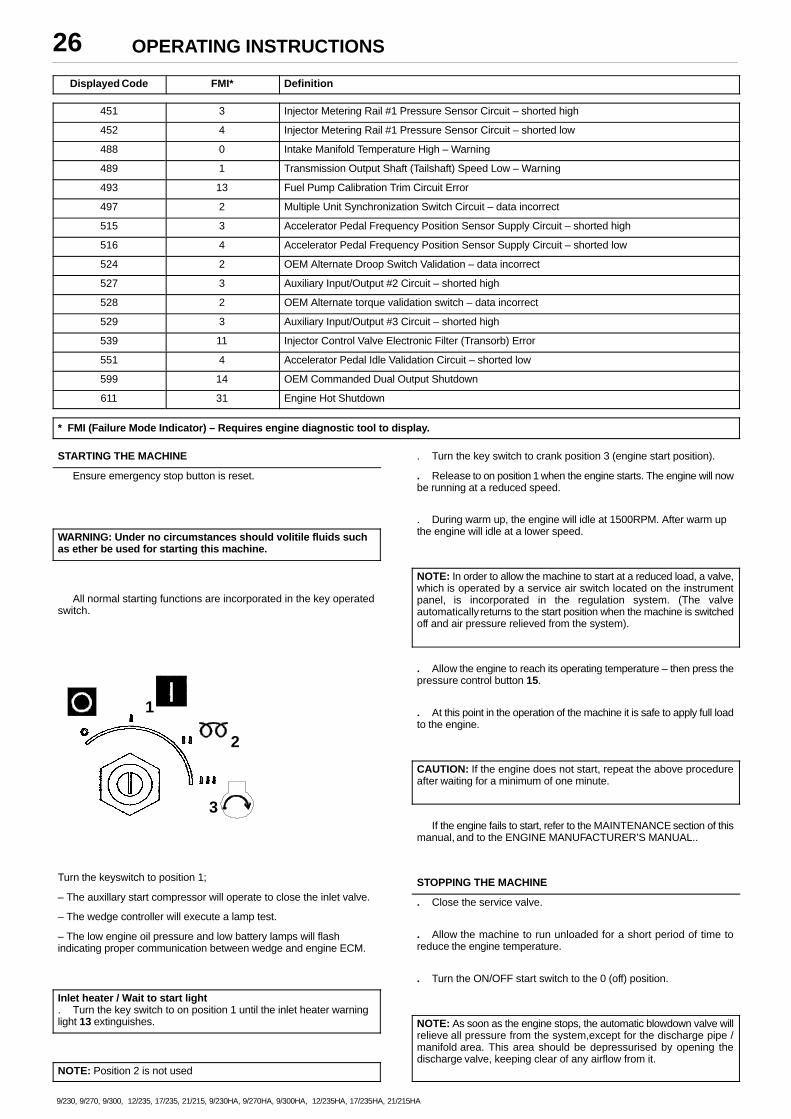
Displayed Code FMI* Definition
451 3 Injector Metering Rail #1 Pressure Sensor Circuit – shorted high
452 4 Injector Metering Rail #1 Pressure Sensor Circuit – shorted low
488 0 Intake Manifold Temperature High – Warning
489 1 Transmission Output Shaft (Tailshaft) Speed Low – Warning
493 13 Fuel Pump Calibration Trim Circuit Error
497 2 Multiple Unit Synchronization Switch Circuit – data incorrect
515 3 Accelerator Pedal Frequency Position Sensor Supply Circuit – shorted high
516 4 Accelerator Pedal Frequency Position Sensor Supply Circuit – shorted low
524 2 OEM Alternate Droop Switch Validation – data incorrect
527 3 Auxiliary Input/Output #2 Circuit – shorted high
528 2 OEM Alternate torque validation switch – data incorrect
529 3 Auxiliary Input/Output #3 Circuit – shorted high
539 11 Injector Control Valve Electronic Filter (Transorb) Error
551 4 Accelerator Pedal Idle Validation Circuit – shorted low
599 14 OEM Commanded Dual Output Shutdown
611 31 Engine Hot Shutdown
* FMI (Failure Mode Indicator) – Requires engine diagnostic tool to display.
STARTING THE MACHINE
Ensure emergency stop button is reset.
WARNING: Under no circumstances should volitile fluids suchas ether be used for starting this machine.
All normal starting functions are incorporated in the key operatedswitch.
1
3
2
Turn the keyswitch to position 1;
– The auxillary start compressor will operate to close the inlet valve.
– The wedge controller will execute a lamp test.
– The low engine oil pressure and low battery lamps will flashindicating proper communication between wedge and engine ECM.
Inlet heater / Wait to start light. Turn the key switch to on position 1 until the inlet heater warninglight 13 extinguishes.
NOTE: Position 2 is not used
. Turn the key switch to crank position 3 (engine start position).
. Release to on position 1 when the engine starts. The engine will nowbe running at a reduced speed.
. During warm up, the engine will idle at 1500RPM. After warm upthe engine will idle at a lower speed.
NOTE: In order to allow the machine to start at a reduced load, a valve,which is operated by a service air switch located on the instrumentpanel, is incorporated in the regulation system. (The valveautomatically returns to the start position when the machine is switchedoff and air pressure relieved from the system).
. Allow the engine to reach its operating temperature – then press thepressure control button 15.
. At this point in the operation of the machine it is safe to apply full loadto the engine.
CAUTION: If the engine does not start, repeat the above procedureafter waiting for a minimum of one minute.
If the engine fails to start, refer to the MAINTENANCE section of thismanual, and to the ENGINE MANUFACTURER’S MANUAL..
STOPPING THE MACHINE
. Close the service valve.
. Allow the machine to run unloaded for a short period of time toreduce the engine temperature.
. Turn the ON/OFF start switch to the 0 (off) position.
NOTE: As soon as the engine stops, the automatic blowdown valve willrelieve all pressure from the system,except for the discharge pipe /manifold area. This area should be depressurised by opening thedischarge valve, keeping clear of any airflow from it.
OPERATING INSTRUCTIONS 27
9/230, 9/270, 9/300, 12/235, 17/235, 21/215, 9/230HA, 9/270HA, 9/300HA, 12/235HA, 17/235HA, 21/215HA
If the automatic blowdown valve fails to operate, then pressure mustbe relieved from the system by means of the service valve(s).
WARNING: When relieving system pressure by means of theservice valve(s), a small amount of pressure will remain in thesystem. No maintenance work should be carried out whilst thissituation exists. This pressure may be relieved by slowlyoperating the manual blowdown valve.
CAUTION: Never allow the machine to stand idle with pressure in thesystem.
EMERGENCY STOPPING
In the event that the unit has to be stopped in an emergency,PRESS THE EMERGENCY STOP SWITCH ON THE FRONT OFTHE MACHINE AND ENSURE THAT IT ENGAGES INDEPRESSED POSITION. (IF FITTED)
If the unit is not fitted with an emergency stop switch, rotate the startswitch to the (0) off position.
RE–STARTING AFTER AN EMERGENCY
Disengage emergency stop control from engaged (depressed)position. (IF FITTED)
If the machine has been switched off because of a machinemalfunction, then identify and correct the fault before attempting tore–start.
If the machine has been switched off for reasons of safety, thenensure that the machine can be operated safely before re–starting.
Refer to the PRIOR TO STARTING and STARTING THE UNITinstructions earlier in this section before re–starting the machine.
MONITORING DURING OPERATION
Should any of the safety shut-down conditions occur, the unit willstop.
Refer to the wedge diagnostic display codes table for a listing ofshutdown conditions.
CAUTION: To ensure an adequate flow of oil to the compressor at lowtemperature, never allow the discharge pressure to fall below 3,5 bar.
DECOMMISSIONING
When the machine is to be permanently decommissioned ordismantled, it is important to ensure that all hazard risks are eithereliminated or notified to the recipient of the machine. In particular:–
. Do not destroy batteries or components containing asbestoswithout containing the materials safely.
. Do not dispose of any pressure vessel that is not clearly markedwith its relevant data plate information or rendered unusable by drilling,cutting etc.
. Do not allow lubricants or coolants to be released into land surfacesor drains.
. Do not dispose of a complete machine without documentationrelating to instructions for its use.
MAINTENANCE28
9/230, 9/270, 9/300, 12/235, 17/235, 21/215, 9/230HA, 9/270HA, 9/300HA, 12/235HA, 17/235HA, 21/215HA
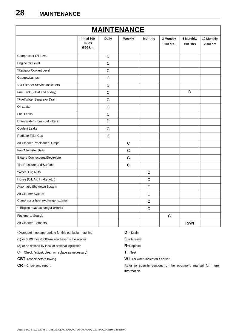
MAINTENANCEInitial 500
miles/850 km
Daily Weekly Monthly 3 Monthly.
500 hrs.
6 Monthly.
1000 hrs
12 Monthly.
2000 hrs
Compressor Oil Level C
Engine Oil Level C
*Radiator Coolant Level C
Gauges/Lamps C
*Air Cleaner Service Indicators C
Fuel Tank (Fill at end of day) C D
*Fuel/Water Separator Drain C
Oil Leaks C
Fuel Leaks C
Drain Water From Fuel Filters D
Coolant Leaks C
Radiator Filler Cap C
Air Cleaner Precleaner Dumps C
Fan/Alternator Belts C
Battery Connections/Electrolyte C
Tire Pressure and Surface C
*Wheel Lug Nuts C
Hoses (Oil, Air, Intake, etc.) C
Automatic Shutdown System C
Air Cleaner System C
Compressor heat exchanger exterior C
* Engine heat exchanger exterior C
Fasteners, Guards C
Air Cleaner Elements R/WI
*Disregard if not appropriate for this particular machine.
(1) or 3000 miles/5000km whichever is the sooner
(2) or as defined by local or national legislation
C = Check (adjust, clean or replace as necessary)
CBT =check before towing.
CR = Check and report
D = Drain
G = Grease
R=Replace
T = Test
W I =or when indicated if earlier.
Refer to specific sections of the operator’s manual for more
information.
MAINTENANCE 29
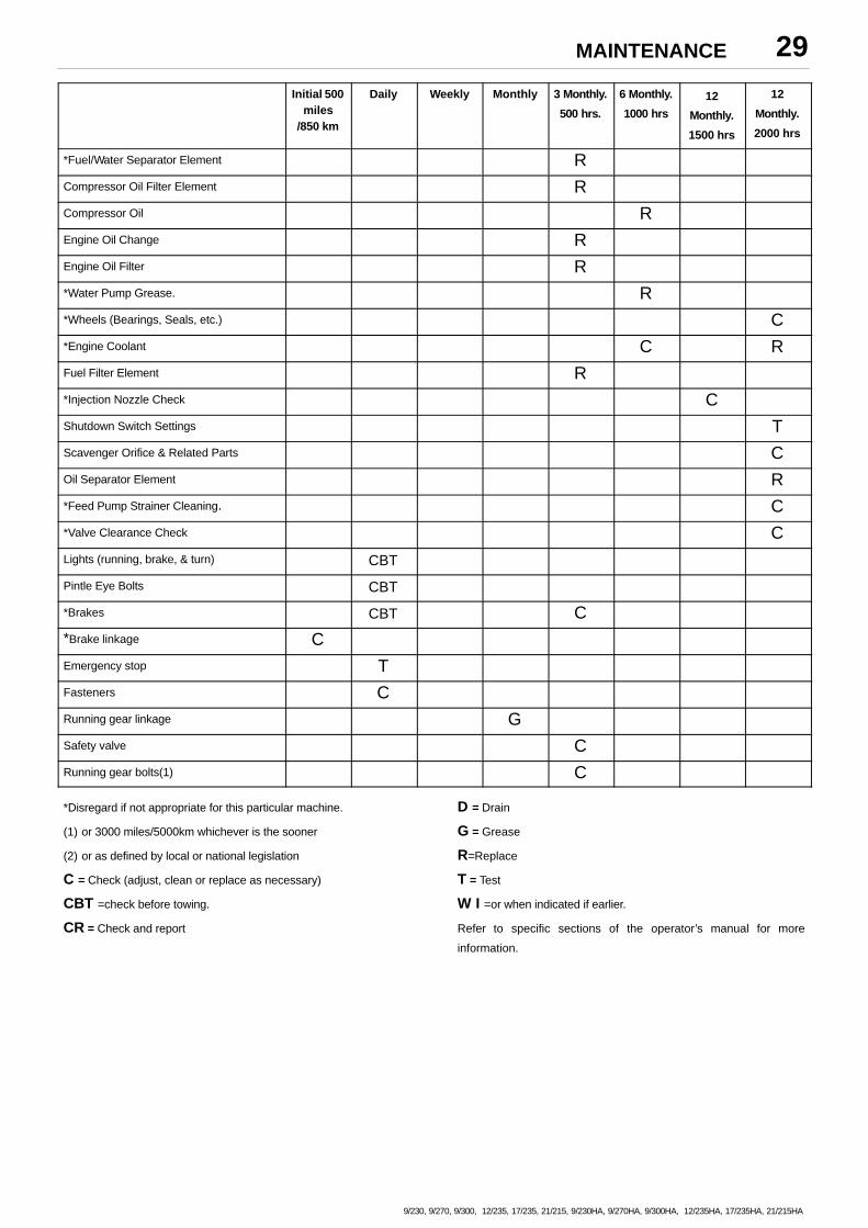
9/230, 9/270, 9/300, 12/235, 17/235, 21/215, 9/230HA, 9/270HA, 9/300HA, 12/235HA, 17/235HA, 21/215HA
Initial 500miles
/850 km
Daily Weekly Monthly 3 Monthly.
500 hrs.
6 Monthly.
1000 hrs
12
Monthly.
1500 hrs
12
Monthly.
2000 hrs
*Fuel/Water Separator Element RCompressor Oil Filter Element RCompressor Oil REngine Oil Change REngine Oil Filter R*Water Pump Grease. R*Wheels (Bearings, Seals, etc.) C*Engine Coolant C RFuel Filter Element R*Injection Nozzle Check CShutdown Switch Settings TScavenger Orifice & Related Parts COil Separator Element R*Feed Pump Strainer Cleaning. C*Valve Clearance Check CLights (running, brake, & turn) CBT
Pintle Eye Bolts CBT
*Brakes CBT C*Brake linkage CEmergency stop TFasteners CRunning gear linkage GSafety valve CRunning gear bolts(1) C
*Disregard if not appropriate for this particular machine.
(1) or 3000 miles/5000km whichever is the sooner
(2) or as defined by local or national legislation
C = Check (adjust, clean or replace as necessary)
CBT =check before towing.
CR = Check and report
D = Drain
G = Grease
R=Replace
T = Test
W I =or when indicated if earlier.
Refer to specific sections of the operator’s manual for more
information.
MAINTENANCE30
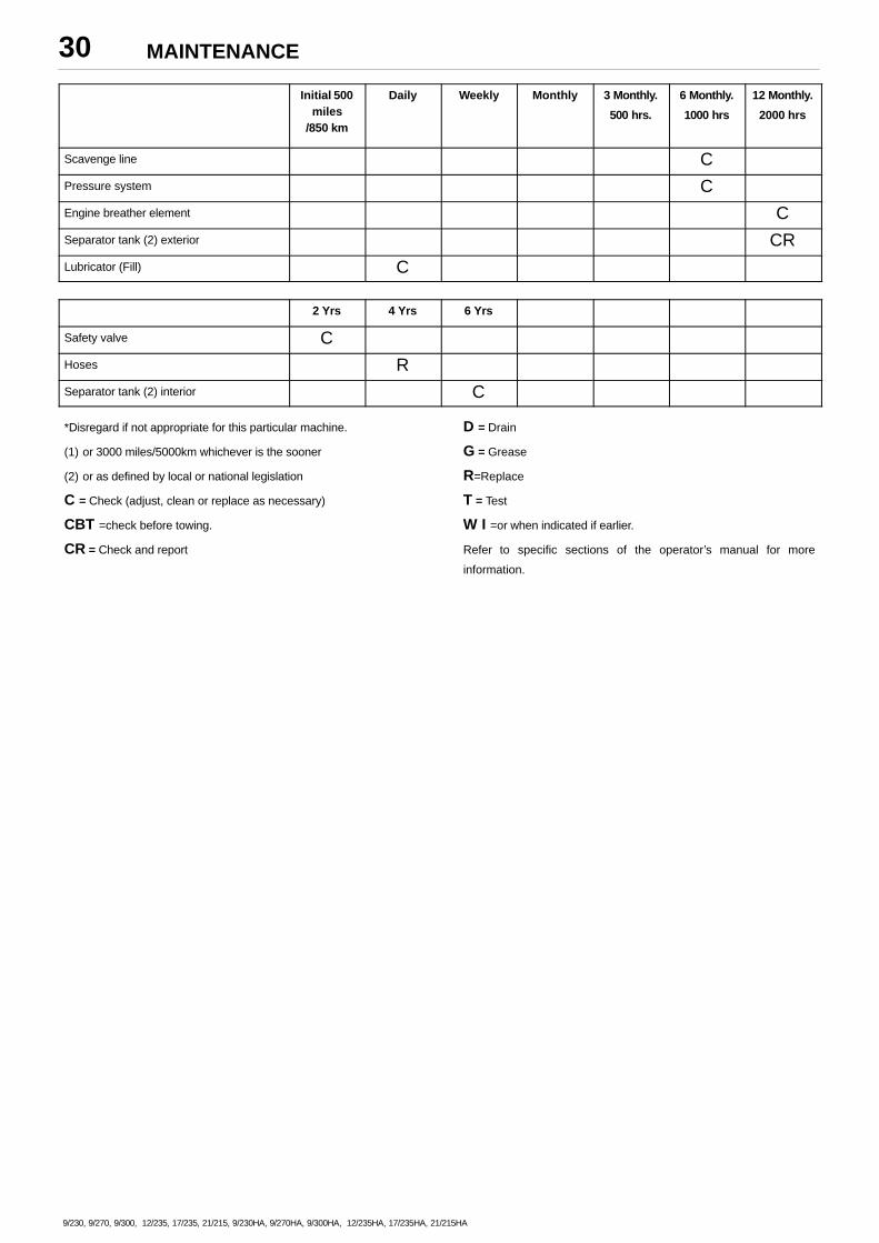
9/230, 9/270, 9/300, 12/235, 17/235, 21/215, 9/230HA, 9/270HA, 9/300HA, 12/235HA, 17/235HA, 21/215HA
Initial 500miles
/850 km
Daily Weekly Monthly 3 Monthly.
500 hrs.
6 Monthly.
1000 hrs
12 Monthly.
2000 hrs
Scavenge line CPressure system CEngine breather element CSeparator tank (2) exterior CRLubricator (Fill) C
2 Yrs 4 Yrs 6 Yrs
Safety valve CHoses RSeparator tank (2) interior C
*Disregard if not appropriate for this particular machine.
(1) or 3000 miles/5000km whichever is the sooner
(2) or as defined by local or national legislation
C = Check (adjust, clean or replace as necessary)
CBT =check before towing.
CR = Check and report
D = Drain
G = Grease
R=Replace
T = Test
W I =or when indicated if earlier.
Refer to specific sections of the operator’s manual for more
information.
MAINTENANCE 31
9/230, 9/270, 9/300, 12/235, 17/235, 21/215, 9/230HA, 9/270HA, 9/300HA, 12/235HA, 17/235HA, 21/215HA
ROUTINE MAINTENANCE
This section refers to the various components which requireperiodic maintenance and replacement.
The SERVICE/MAINTENANCE CHART indicates the variouscomponents’ descriptions and the intervals when maintenance has totake place. Oil capacities, etc., can be found in the GENERALINFORMATION section of this manual.
For any specification or specific requirement on service orpreventative maintenance for the engine, refer to the EngineManufacturer’s Manual.
Compressed air can be dangerous if incorrectly handled. Beforedoing any work on the unit, ensure that all pressure is vented from thesystem and that the machine cannot be started accidentally.
If the automatic blowdown fails to operate, then pressure must begradually relieved by operating the manual blowdown valve. Suitablepersonal protective equipment should be worn.
Ensure that maintenance personnel are adequately trained,competent and have read the Maintenance Manuals.
Prior to attempting any maintenance work, ensure that:–
. all air pressure is fully discharged and isolated from the system. Ifthe automatic blowdown valve is used for this purpose, then allowenough time for it to complete the operation.
NOTE: Pressure will always remain in the part of the system betweenthe minimum pressure valve and the discharge valve after operation ofthe auto blowdown valve.
THIS PRESSURE MUST BE RELIEVED BY CAREFULLY:
(a) DISCONNECTING ANY DOWNSTREAM EQUIPMENT.
(b) OPENING THE DISCHARGE VALVE TO ATMOSPHERE.
(USE HEARING PROTECTION IF NECESSARY).
. the machine cannot be started accidently or otherwise, by postingwarning signs and/or fitting appropriate anti–start devices.
. all residual electrical power sources (mains and battery) areisolated.
Prior to opening or removing panels or covers to work insidea machine, ensure that:–
. anyone entering the machine is aware of the reduced level ofprotection and the additional hazards, including hot surfaces andintermittently moving parts.
. the machine cannot be started accidently or otherwise, by postingwarning signs and/or fitting appropriate anti–start devices.
Prior to attempting any maintenance work on a runningmachine, ensure that:–
. the work carried out is limited to only those tasks which require themachine to run.
. the work carried out with safety protection devices disabled orremoved is limited to only those tasks which require the machine to berunning with safety protection devices disabled or removed.
. all hazards present are known (e.g. pressurised components,electrically live components, removed panels, covers and guards,extreme temperatures, inflow and outflow of air, intermittently movingparts, safety valve discharge etc.).
. appropriate personal protective equipment is worn.
. loose clothing, jewellery, long hair etc. is made safe.
. warning signs indicating that Maintenance Work is in Progress areposted in a position that can be clearly seen.
Upon completion of maintenance tasks and prior to returningthe machine into service, ensure that:–
. the machine is suitably tested.
. all guards and safety protection devices are refitted.
. all panels are replaced, canopy and doors closed.
. hazardous materials are effectively contained and disposed of.
PROTECTIVE SHUTDOWN SYSTEM
Refer to the Wedge diagnostic display codes table for a listing ofshutdown conditions.
Low engine fuel level switch.
At three month intervals, test the low engine fuel level switch circuitas follows:
. Start the machine.
Note: Do not press the load button.
. Disconnect the switch, the machine should shutdown.
. Re–connect the switch.
At twelve month intervals, test the low engine fuel level switch byremoving and operating the float manually.
CAUTION: Never remove or replace switches when the machineis running.
SCAVENGE LINE
The scavenge line runs from the combined orifice/drop tube in theseparator tank, to the orifice fitting located in the airend.
Examine the orifice, check valve and hoses at every service or inthe event of oil carryover into the discharge air.
It is good preventative maintenance to check that the scavenge lineand tube are clear of any obstruction each time the compressorlubricant is changed as any blockage will result in oil carryover into thedischarge air.
COMPRESSOR OIL FILTER
Refer to the MAINTENANCE CHART in this section for therecommended servicing intervals.
Removal
WARNING: Do not remove the filter(s) without first making surethat the machine is stopped and the system has been completelyrelieved of all air pressure. (Refer to STOPPING THE UNIT in theOPERATING INSTRUCTIONS section of this manual).
MAINTENANCE32
9/230, 9/270, 9/300, 12/235, 17/235, 21/215, 9/230HA, 9/270HA, 9/300HA, 12/235HA, 17/235HA, 21/215HA
Clean the exterior of the filter housing and remove the spin–onelement by turning it in a counter–clockwise direction.
Inspection
Examine the filter element.
CAUTION: If there is any indication of the formation of varnishes,shellacs or lacquers on the filter element, it is a warning that thecompressor lubricating and cooling oil has deteriorated and that itshould be changed immediately. Refer to LUBRICATION later in thissection.
Reassembly
Clean the filter gasket contact area and install the new element byscrewing in a clockwise direction until the gasket makes contact withthe filter housing. Tighten a further 1/2 to 3/4 of a revolution.
CAUTION: Start the machine (refer to PRIOR TO STARTING andSTARTING THE UNIT in the OPERATING INSTRUCTIONS sectionof this manual) and check for leakage before the machine is put backinto service.
COMPRESSOR OIL SEPARATOR ELEMENT
Refer to the SERVICE / MAINTENANCE CHART in this section forservice intervals.
Removal
WARNING: Do not remove the filter(s) without first making surethat the machine is stopped and the system has been completelyrelieved of all air pressure. (Refer to STOPPING THE UNIT in theOPERATING INSTRUCTIONS section of this manual).
Disconnect all hoses and tubes from the separator tank cover plate.Remove the drop–tube from the separator tank cover plate and thenremove the cover plate. Remove the separator element.
Inspection
Examine the filter element. Examine all hoses and tubes, andreplace if necessary.
Reassembly
Thoroughly clean the orifice/drop tube and filter gasket contact areabefore reassembly. Install the new element.
WARNINGDo not remove the staple from the anti–static gasket on the
separator element since it serves to ground any possible staticbuild–up. Do not use gasket sealant since this will affect electricalconductance.
Reposition the cover plate, taking care not to damage the gasket,and replace the cover plate screws tightening in a criss–cross patternto the recommended torque (refer to the TORQUE SETTING TABLElater in this section).
Replace the drop–tube and reconnect all hoses and tubes to theseparator tank cover plate.
Replace the compressor oil (refer to LUBRICATION later in thissection).
CAUTION: Start the machine (refer to PRIOR TO STARTING andSTARTING THE UNIT in the OPERATING INSTRUCTIONS sectionof this manual) and check for leakage before the machine is put backinto service.
COMPRESSOR OIL COOLER AND ENGINE RADIATOR AIRCHARGE COOLER
When grease, oil and dirt accumulate on the exterior surfaces of theoil cooler and radiator, the efficiency is impaired. It is recommended thateach month the oil cooler and radiator be cleaned by directing a jet ofcompressed air, (carrying if possible a non–flammable cleaningsolvent) over the exterior core of the cooler/radiator. This shouldremove any accumulation of oil, grease and dirt from the exterior coreof the cooler so that the entire cooling area can radiate the heat of thelubricating and cooling oil/water into the air stream.
WARNING: Hot engine coolant and steam can cause injury. Whenadding coolant or antifreeze solution to the engine radiator, stopthe engine at least one minute prior to releasing the radiator fillercap. Using a cloth to protect the hand, slowly release the filler cap,absorbing any released fluid with the cloth. Do not remove thefiller cap until all excess fluid is released and the engine coolingsystem fully depressurised.
WARNING: Follow the instructions provided by the antifreezesupplier when adding or draining the antifreeze solution. It isadvisable to wear personal protective equipment to prevent skinand eye contact with the antifreeze solution.
AIR FILTER ELEMENT
The air filter should be inspected regularly (refer to theSERVICE/MAINTENANCE CHART) and the element replaced whenthe restriction indicator lamp illuminates. The dust collector box(es)should be cleaned daily (more frequently in dusty operatingconditions) and not allowed to become more than half full.
The safety element should be renewed every 3000 hours or everythird change of the main element, whichever comes first.
Removal
CAUTION: Never remove and replace element(s) when the machineis running.
Clean the exterior of the filter housing and remove the filter elementby releasing the nut.
If the safety element is to be renewed, thoroughly clean the interiorof the filter housing prior to removing the safety element.
Inspection
Check for cracks, holes or any other damage to the element byholding it up to a light source, or by passing a lamp inside.
MAINTENANCE 33
9/230, 9/270, 9/300, 12/235, 17/235, 21/215, 9/230HA, 9/270HA, 9/300HA, 12/235HA, 17/235HA, 21/215HA
CAUTION: If inspection reveals damage to the main element, thesafety element must be replaced.
Check the seal at the end of the element and replace if any sign ofdamage is evident.
Reassembly
Assemble the new element into the filter housing ensuring that theseal seats properly.
Secure the element in the housing by hand tightening the nut.
Assemble the dust collector box parts, ensuring that they arecorrectly positioned.
Before restarting the machine, check that all clamps are tight.
NOTE: In the event that a new filter element is not readily available, theelement can be re–used after cleaning. In this case the followingprocedure must be carried out:
Clean the element by directing a jet of clean, dry compressed air,no more than 5 bar, at an angle of 45 degrees to the outside of theelement. Carefully blow any dust from each fold of the element.
Compressed air cleaning is only recommended when a newelement is not available.
CAUTION: Safety elements must not be cleaned and re–used.
VENTILATION
Always check that the air inlets and outlets are clear of debris etc.
CAUTION: NEVER clean by blowing air inwards.
COOLING FAN DRIVE
Periodically check that the fan mounting bolt in the fan hub has notloosened. If, for any reason, it becomes necessary to remove the fanor re–tighten the fan mounting bolt, apply a good grade of commerciallyavailable thread locking compound to the bolt threads and tighten to thetorque value shown in the TORQUE SETTING TABLE later in thissection.
The fan belt(s) should be checked regularly for wear and correcttensioning.
FUEL SYSTEM
The fuel tank should be filled daily or every eight hours. To minimisecondensation in the fuel tank(s), it is advisable to top up after themachine is shut down or at the end of each working day. At six monthintervals drain any sediment or condensate that may haveaccumulated in the tank(s).
FUEL FILTER WATER SEPARATOR
The fuel filter water separator contains a filter element which shouldbe replaced at regular intervals (see the SERVICE/MAINTENANCECHART).
CHARGE COOLER PIPEWORK:–
Inspect all hoses and clips on the charge cooler pipe work.
Engine damage will occur if the charge cooling system leaks.
HOSES
All components of the engine cooling air intake system should bechecked periodically to keep the engine at peak efficiency.
At the recommended intervals, (see theSERVICE/MAINTENANCE CHART), inspect all of the intake lines tothe air filter, and all flexible hoses used for air lines, oil lines and fuellines.
Periodically inspect all pipework for cracks, leaks, etc. and replaceimmediately if damaged.
ELECTRICAL SYSTEM
WARNING: Always disconnect the battery cables beforeperforming any maintenance or service.
Inspect the safety shutdown system switches and the instrumentpanel relay contacts for evidence of arcing and pitting. Clean wherenecessary.
Check the mechanical action of the components.
Check the security of electrical terminals on the switches and relaysi.e. nuts or screws loose, which may cause local hot spot oxidation.
Inspect the components and wiring for signs of overheating i.e.discolouration, charring of cables, deformation of parts, acrid smellsand blistered paint.
BATTERY
Keep the battery terminals and cable clamps clean and lightlycoated with petroleum jelly to prevent corrosion.
The retaining clamp should be kept tight enough to prevent thebattery from moving.
PRESSURE SYSTEM
At 3 month intervals it is necessary to inspect the externalsurfaces of the system (from the airend through to the dischargevalve(s)) including hoses, tubes, tube fittings and the separator tank,for visible signs of impact damage, excessive corrosion, abrasion,tightness and chafing. Any suspect parts should be replaced beforethe machine is put back into service.
TYRES/TYRE PRESSURE
See the GENERAL INFORMATION section of this manual.
MAINTENANCE34
9/230, 9/270, 9/300, 12/235, 17/235, 21/215, 9/230HA, 9/270HA, 9/300HA, 12/235HA, 17/235HA, 21/215HA
RUNNING GEAR/WHEELS
Check the wheel nut torque 20 miles (30 kilometres) after refittingthe wheels. Refer to the TORQUE SETTING TABLE later in thissection.
The bolts securing the running gear to the chassis should bechecked periodically for tightness (refer to theSERVICE/MAINTENANCE CHART for frequency) and re–tightenedwhere necessary. Refer to the TORQUE SETTING TABLE later in thissection.
LUBRICATION
The engine is initially supplied with engine oil sufficient for a nominalperiod of operation (for more information, consult The EngineManufacturer’s Manual).
CAUTION: Always check the oil levels before a new machine is put intoservice.
If, for any reason, the unit has been drained, it must be re–filled withnew oil before it is put into operation.
ENGINE LUBRICATING OIL
The engine oil should be changed at the engine manufacturer’srecommended intervals. Refer to the SERVICE / MAINTENANCECHART.
ENGINE LUBRICATING OIL SPECIFICATION
Refer to the Engine Manufacturer’s Manual or LubricationSpecification list.
ENGINE OIL FILTER ELEMENT
The engine oil filter element should be changed at the enginemanufacturer’s recommended intervals. Refer to the SERVICE /MAINTENANCE CHART..
COMPRESSOR LUBRICATING OIL
Refer to the SERVICE/MAINTENANCE CHART in this section forservice intervals.
NOTE: If the machine has been operating under adverse conditions,or has suffered long shutdown periods, then more frequent serviceintervals will be required.
WARNING: DO NOT, under any circumstances, remove any drainplugs or the oil filler plug from the compressor lubricating andcooling system without first making sure that the machine isstopped and the system has been completely relieved of all airpressure (refer to STOPPING THE UNIT in the OPERATINGINSTRUCTIONS section of this manual).
Completely drain the receiver/separator system including the pipingand oil cooler by removing the drain plug(s) and collecting the used oilin a suitable container.
Replace the drain plug(s) ensuring that each one is secure.
NOTE: If the oil is drained immediately after the machine has beenrunning, then most of the sediment will be in suspension and willtherefore drain more readily.
CAUTION: Some oil mixtures are incompatible and result in theformation of varnishes, shellacs or lacquers which may be insoluble.
NOTE: Always specify INGERSOLL–RAND Pro–TecTM oil for useat all ambient temperatures above –23�C.
RUNNING GEAR WHEEL BEARINGS
Wheel bearings should be packed with grease every 6 months. Thetype of grease used should conform to specification MIL–G–10924.
MAINTENANCE 35
9/230, 9/270, 9/300, 12/235, 17/235, 21/215, 9/230HA, 9/270HA, 9/300HA, 12/235HA, 17/235HA, 21/215HA
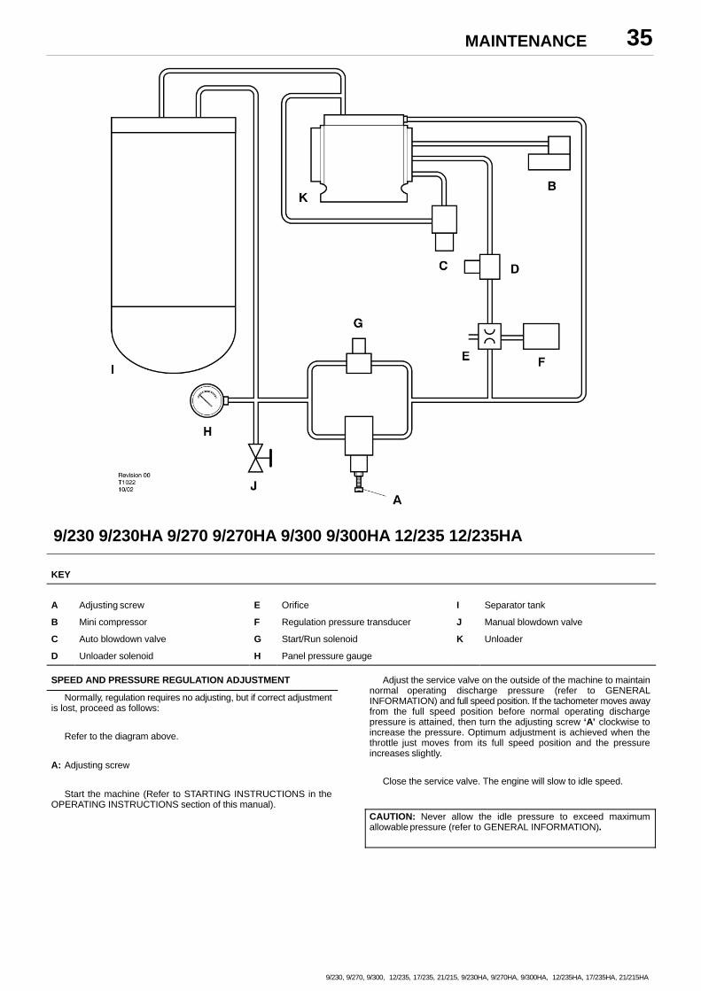
9/230 9/230HA 9/270 9/270HA 9/300 9/300HA 12/235 12/235HA
KEY
A Adjusting screw E Orifice I Separator tank
B Mini compressor F Regulation pressure transducer J Manual blowdown valve
C Auto blowdown valve G Start/Run solenoid K Unloader
D Unloader solenoid H Panel pressure gauge
SPEED AND PRESSURE REGULATION ADJUSTMENT
Normally, regulation requires no adjusting, but if correct adjustmentis lost, proceed as follows:
Refer to the diagram above.
A: Adjusting screw
Start the machine (Refer to STARTING INSTRUCTIONS in theOPERATING INSTRUCTIONS section of this manual).
Adjust the service valve on the outside of the machine to maintainnormal operating discharge pressure (refer to GENERALINFORMATION) and full speed position. If the tachometer moves awayfrom the full speed position before normal operating dischargepressure is attained, then turn the adjusting screw ‘A’ clockwise toincrease the pressure. Optimum adjustment is achieved when thethrottle just moves from its full speed position and the pressureincreases slightly.
Close the service valve. The engine will slow to idle speed.
CAUTION: Never allow the idle pressure to exceed maximumallowable pressure (refer to GENERAL INFORMATION).
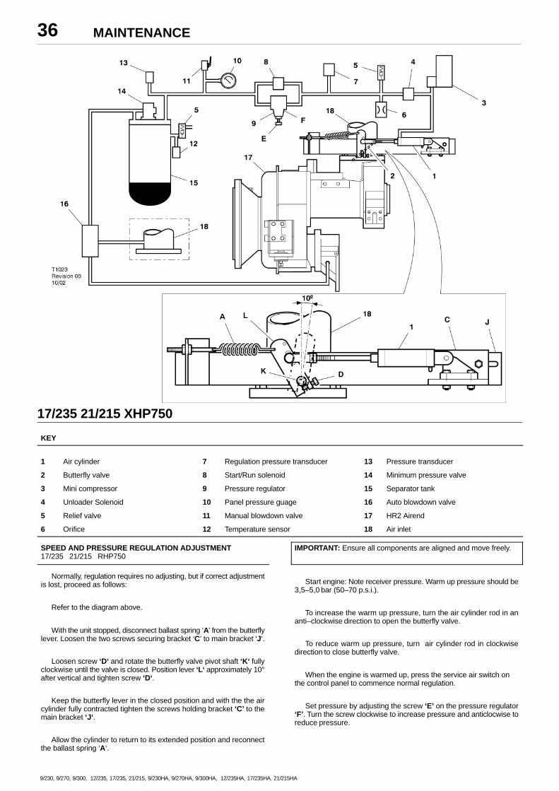
MAINTENANCE36
9/230, 9/270, 9/300, 12/235, 17/235, 21/215, 9/230HA, 9/270HA, 9/300HA, 12/235HA, 17/235HA, 21/215HA
17/235 21/215 XHP750
KEY
1 Air cylinder 7 Regulation pressure transducer 13 Pressure transducer
2 Butterfly valve 8 Start/Run solenoid 14 Minimum pressure valve
3 Mini compressor 9 Pressure regulator 15 Separator tank
4 Unloader Solenoid 10 Panel pressure guage 16 Auto blowdown valve
5 Relief valve 11 Manual blowdown valve 17 HR2 Airend
6 Orifice 12 Temperature sensor 18 Air inlet
SPEED AND PRESSURE REGULATION ADJUSTMENT17/235 21/215 RHP750
Normally, regulation requires no adjusting, but if correct adjustmentis lost, proceed as follows:
Refer to the diagram above.
With the unit stopped, disconnect ballast spring ‘A’ from the butterflylever. Loosen the two screws securing bracket ‘C’ to main bracket ‘J‘.
Loosen screw ‘D‘ and rotate the butterfly valve pivot shaft ‘K‘ fullyclockwise until the valve is closed. Position lever ‘L‘ approximately 10°after vertical and tighten screw ‘D‘.
Keep the butterfly lever in the closed position and with the the aircylinder fully contracted tighten the screws holding bracket ‘C’ to themain bracket ‘J‘.
Allow the cylinder to return to its extended position and reconnectthe ballast spring ‘A‘.
IMPORTANT: Ensure all components are aligned and move freely.
Start engine: Note receiver pressure. Warm up pressure should be3,5–5,0 bar (50–70 p.s.i.).
To increase the warm up pressure, turn the air cylinder rod in ananti–clockwise direction to open the butterfly valve.
To reduce warm up pressure, turn air cylinder rod in clockwisedirection to close butterfly valve.
When the engine is warmed up, press the service air switch onthe control panel to commence normal regulation.
Set pressure by adjusting the screw ‘E’ on the pressure regulator‘F’. Turn the screw clockwise to increase pressure and anticlocwise toreduce pressure.
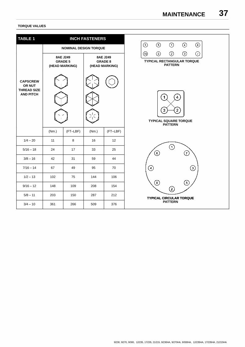
MAINTENANCE 37
9/230, 9/270, 9/300, 12/235, 17/235, 21/215, 9/230HA, 9/270HA, 9/300HA, 12/235HA, 17/235HA, 21/215HA
TORQUE VALUES
TABLE 1 INCH FASTENERS
NOMINAL DESIGN TORQUE
8AE J249GRADE 5
(HEAD MARKING)
8AE J249GRADE 8
(HEAD MARKING)TYPICAL RECTANGULAR TORQUE
PATTERN
CAPSCREWOR NUT
THREAD SIZEAND PITCH
TYPICAL SQUARE TORQUEPATTERN
(Nm.) (FT–LBF) (Nm.) (FT–LBF)
1/4 – 20 11 8 16 12
5/16 – 18 24 17 33 25
3/8 – 16 42 31 59 44
7/16 – 14 67 49 95 70
1/2 – 13 102 75 144 106
9/16 – 12 148 109 208 154
5/8 – 11 203 150 287 212TYPICAL CIRCULAR TORQUE
3/4 – 10 361 266 509 376
TYPICAL CIRCULAR TORQUEPATTERN
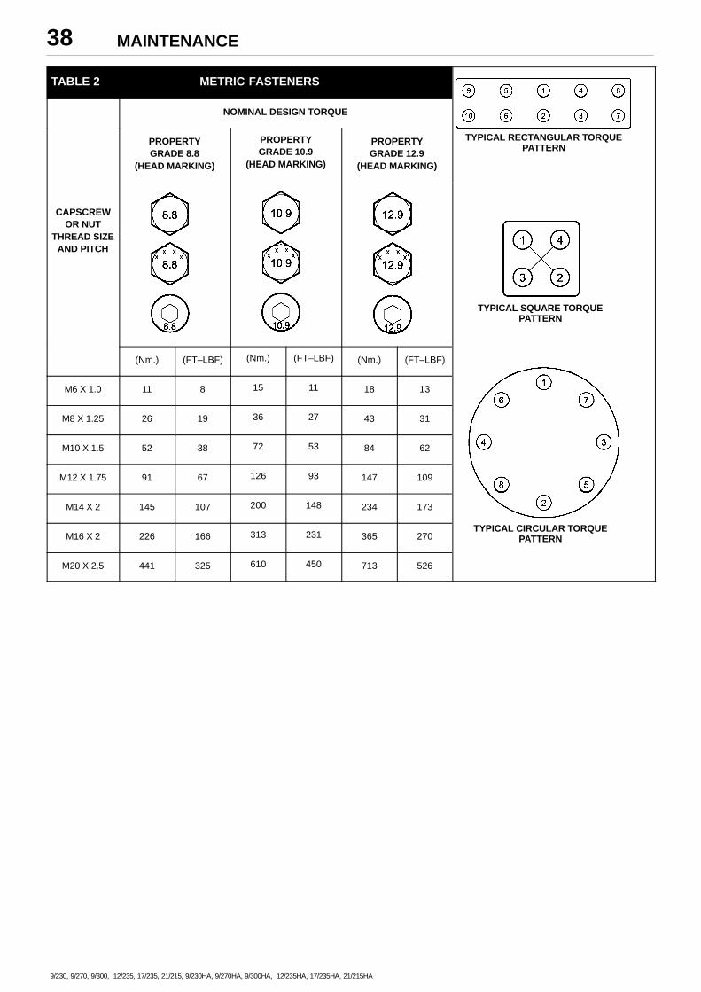
MAINTENANCE38
9/230, 9/270, 9/300, 12/235, 17/235, 21/215, 9/230HA, 9/270HA, 9/300HA, 12/235HA, 17/235HA, 21/215HA
TABLE 2 METRIC FASTENERS
NOMINAL DESIGN TORQUE
PROPERTYGRADE 8.8
(HEAD MARKING)
PROPERTYGRADE 10.9
(HEAD MARKING)
PROPERTYGRADE 12.9
(HEAD MARKING)
TYPICAL RECTANGULAR TORQUEPATTERN
CAPSCREWOR NUT
THREAD SIZEAND PITCH
TYPICAL SQUARE TORQUEPATTERN
(Nm.) (FT–LBF) (Nm.) (FT–LBF) (Nm.) (FT–LBF)
M6 X 1.0 11 8 15 11 18 13
M8 X 1.25 26 19 36 27 43 31
M10 X 1.5 52 38 72 53 84 62
M12 X 1.75 91 67 126 93 147 109
M14 X 2 145 107 200 148 234 173
M16 X 2 226 166 313 231 365 270TYPICAL CIRCULAR TORQUE
PATTERN
M20 X 2.5 441 325 610 450 713 526
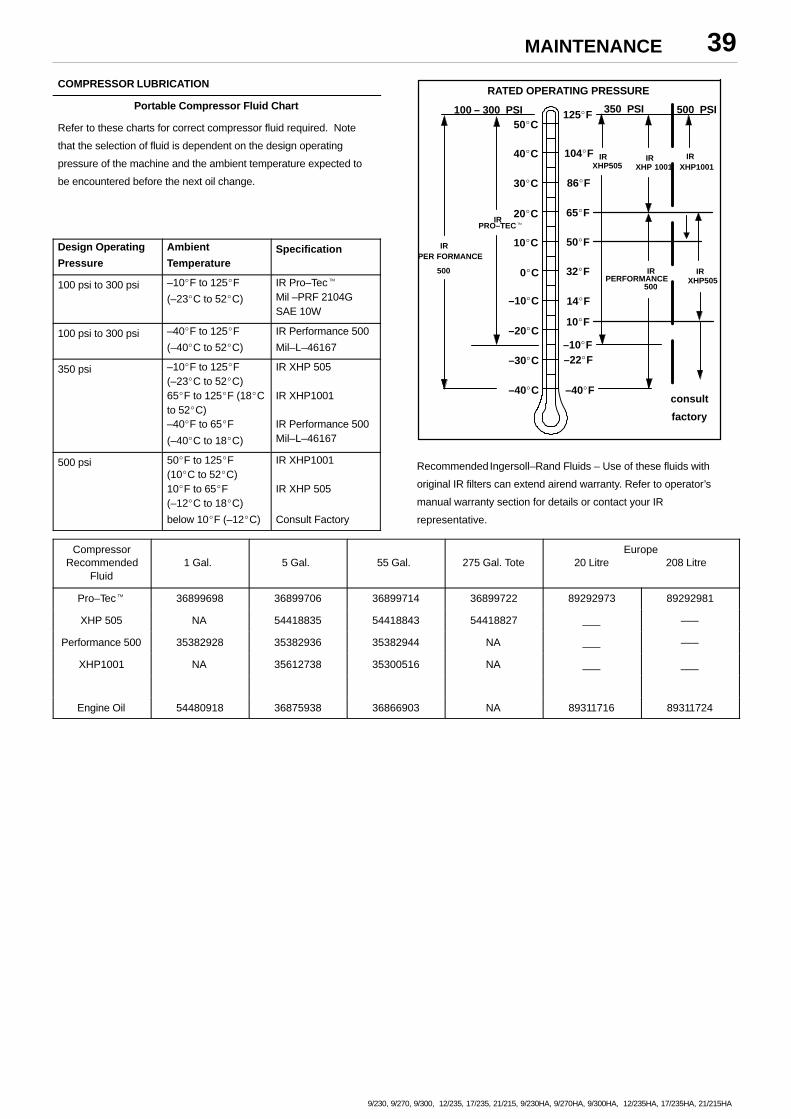
MAINTENANCE 39
9/230, 9/270, 9/300, 12/235, 17/235, 21/215, 9/230HA, 9/270HA, 9/300HA, 12/235HA, 17/235HA, 21/215HA
COMPRESSOR LUBRICATION
Portable Compressor Fluid Chart
Refer to these charts for correct compressor fluid required. Note
that the selection of fluid is dependent on the design operating
pressure of the machine and the ambient temperature expected to
be encountered before the next oil change.
Design Operating
Pressure
Ambient
TemperatureSpecification
100 psi to 300 psi –10�F to 125�F
(–23�C to 52�C)
IR Pro–Tec�Mil –PRF 2104GSAE 10W
100 psi to 300 psi –40�F to 125�F
(–40�C to 52�C)
IR Performance 500
Mil–L–46167
350 psi –10�F to 125�F(–23�C to 52�C)65�F to 125�F (18�Cto 52�C) –40�F to 65�F
(–40�C to 18�C)
IR XHP 505
IR XHP1001
IR Performance 500Mil–L–46167
500 psi 50�F to 125�F (10�C to 52�C)10�F to 65�F (–12�C to 18�C)
below 10�F (–12�C)
IR XHP1001
IR XHP 505
Consult Factory
IRXHP505
IRXHP1001
IRPER FORMANCE
500
IRPRO–TEC�
100 – 300 PSI
RATED OPERATING PRESSURE
350 PSI 500 PSI
IRXHP 1001
IR
500PERFORMANCE
IRXHP505
10�F
125�F50�C
40�C
30�C
20�C
10�C
0�C
–10�C
–20�C
–30�C
–40�C
104�F
86�F
65�F
50�F
32�F
14�F
–10�F–22�F
–40�Fconsult
factory
Recommended Ingersoll–Rand Fluids – Use of these fluids with
original IR filters can extend airend warranty. Refer to operator’s
manual warranty section for details or contact your IR
representative.
CompressorRecommended
Fluid1 Gal. 5 Gal. 55 Gal. 275 Gal. Tote
Europe20 Litre 208 Litre
Pro–Tec� 36899698 36899706 36899714 36899722 89292973 89292981
XHP 505 NA 54418835 54418843 54418827 ___ –––
Performance 500 35382928 35382936 35382944 NA ___ –––
XHP1001 NA 35612738 35300516 NA ___ ___
Engine Oil 54480918 36875938 36866903 NA 89311716 89311724
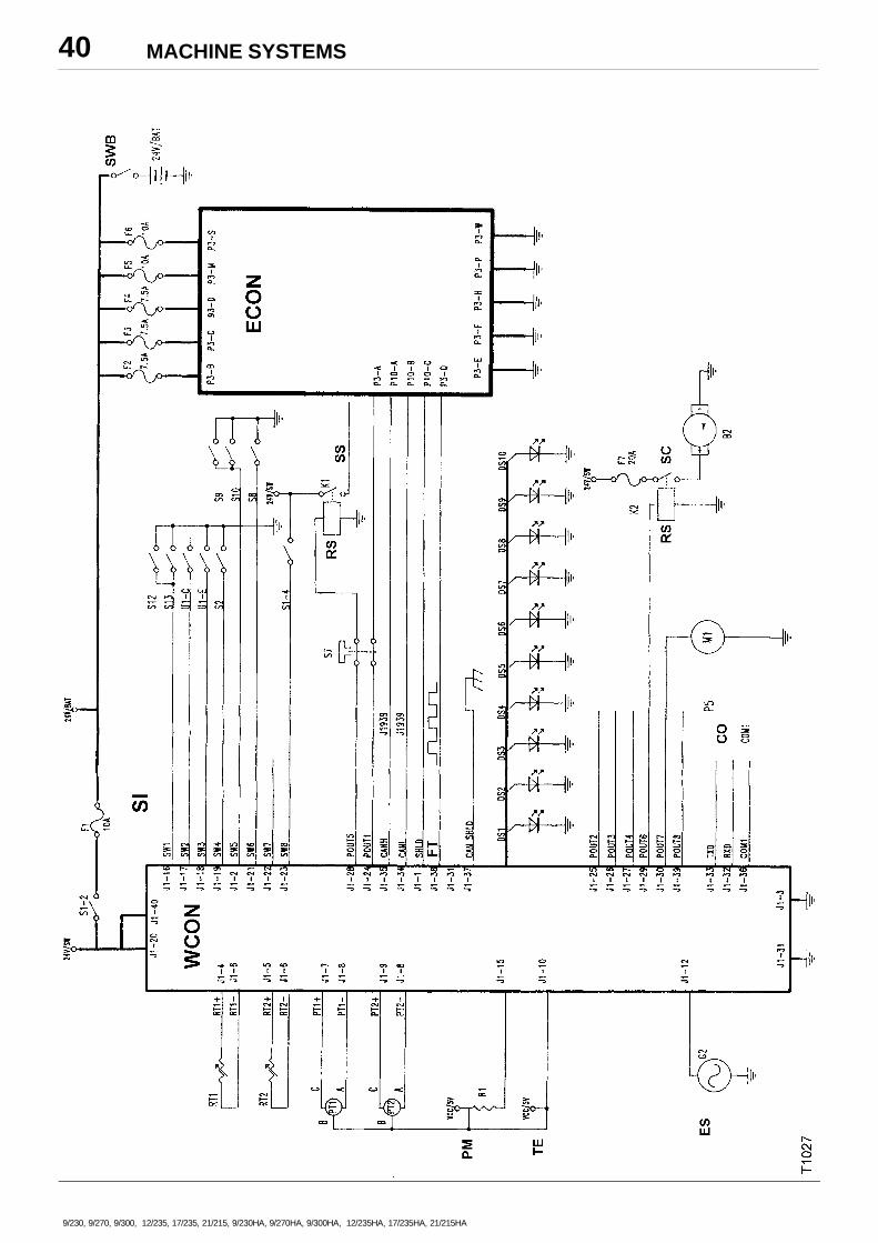
MACHINE SYSTEMS40
9/230, 9/270, 9/300, 12/235, 17/235, 21/215, 9/230HA, 9/270HA, 9/300HA, 12/235HA, 17/235HA, 21/215HA
MACHINE SYSTEMS 41
9/230, 9/270, 9/300, 12/235, 17/235, 21/215, 9/230HA, 9/270HA, 9/300HA, 12/235HA, 17/235HA, 21/215HA
KEY
BAT Battery
CO RS232C comms
DS1 LED, high airend temperature
DS2 LED, low engine oil pressure
DS3 LED, high engine temperature
DS4 LED, low fuel
DS5 LED, alternator
DS6 LED, low coolant
DS7 LED, air filter restriction
DS8 LED, IQ filter restriction
DS9 LED, Engine fault
DS10 LED, compressor fault
ECON Engine controller
ES Engine speed
FT Frequency throttle.Range = 150Hz(1200 RPM) to 375Hz(1800 RPM) at 24VDC
G7 Fly wheel
POUT1 Engine key switch
POUT2 Solenoid, start/run
POUT3 Low fuel warning beacon
POUT4 Spare
POUT5 Start relay
POUT6 Start compressor
POUT7 Hour meter
POUT8 Solenoid, unloader
PT1 Pressure trancducer, separator tank.
0–225 PSIG – 9/235, 9/270, 9/300, 12/235.0–225 PSIG – HP935, VHP750, MHP825, XP1060.
0–500 PSIG – 21/215, 17/235, XHP750.
PT2 Pressure trancducer, regulation system 0–100 PSIG
PM Plug, machine ID
RS Relay–spst
RT1 Thermistor, seperator tank temperature –30 – 255�F
RT2 Thermistor, Thermistor, airend discharge temperature –30 –
255�F
S7 Emergency stop
SC Start compressor
SI Switch inputs
SS Starter solenoid
SW1 IQ filter restriction
SW2 Alert, low fuel
SW3 Low fuel shutdown
SW4 Switch, service air
SW5 Air filter rest (option)
SW6 Switch, airend oil pressure (12PSI N.O.)
SW7 Spare
SW8 Switch, start
SWB Switch batery disconnect
TE Transducer exitation
WCON Wedge controller
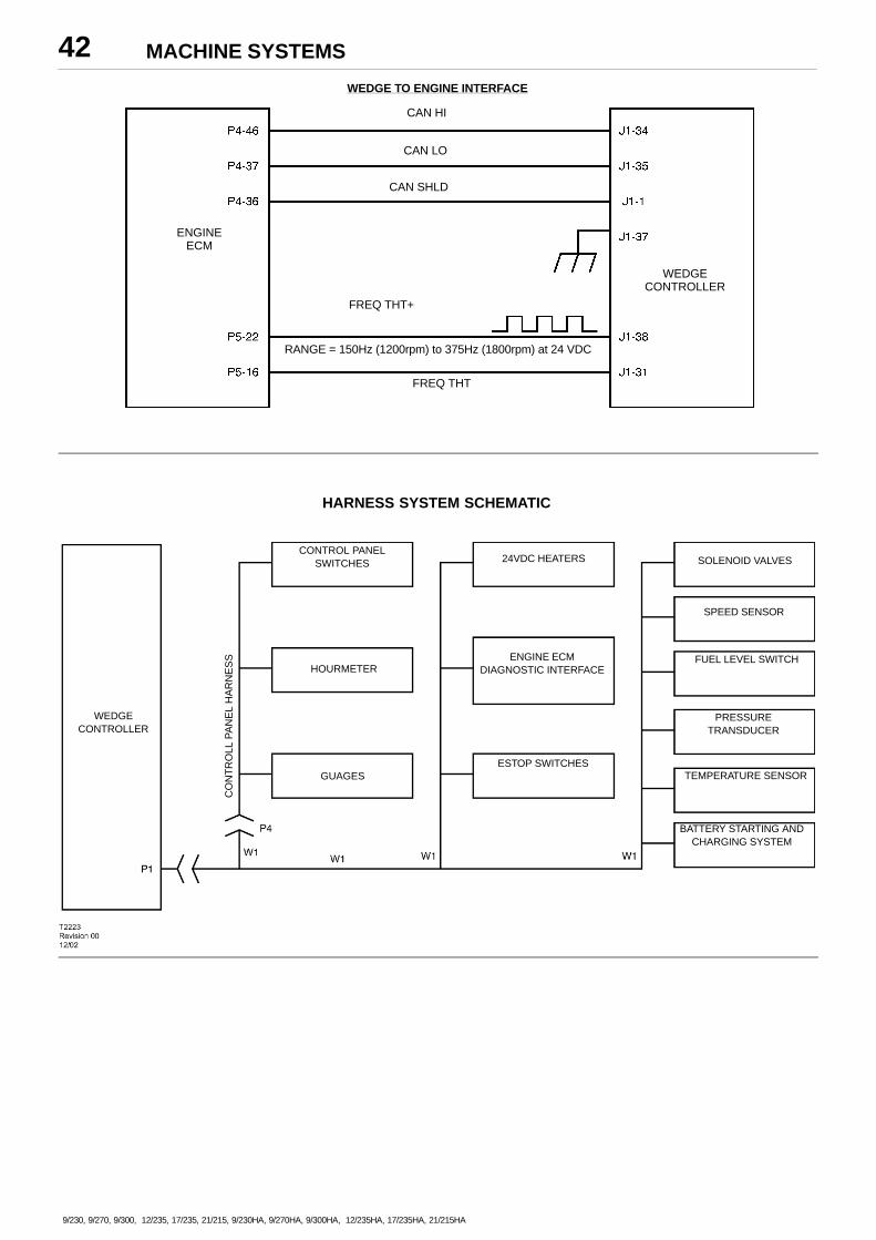
MACHINE SYSTEMS42
9/230, 9/270, 9/300, 12/235, 17/235, 21/215, 9/230HA, 9/270HA, 9/300HA, 12/235HA, 17/235HA, 21/215HA
CAN HI
CAN LO
CAN SHLD
RANGE = 150Hz (1200rpm) to 375Hz (1800rpm) at 24 VDC
FREQ THT
WEDGECONTROLLER
FREQ THT+
ENGINEECM
WEDGE TO ENGINE INTERFACE
ENGINE ECMDIAGNOSTIC INTERFACE
CO
NT
RO
LL P
AN
EL
HA
RN
ES
S
SOLENOID VALVES24VDC HEATERS
GUAGES
HOURMETER
CONTROL PANELSWITCHES
WEDGECONTROLLER
SPEED SENSOR
FUEL LEVEL SWITCH
PRESSURETRANSDUCER
TEMPERATURE SENSOR
BATTERY STARTING ANDCHARGING SYSTEM
ESTOP SWITCHES
HARNESS SYSTEM SCHEMATIC
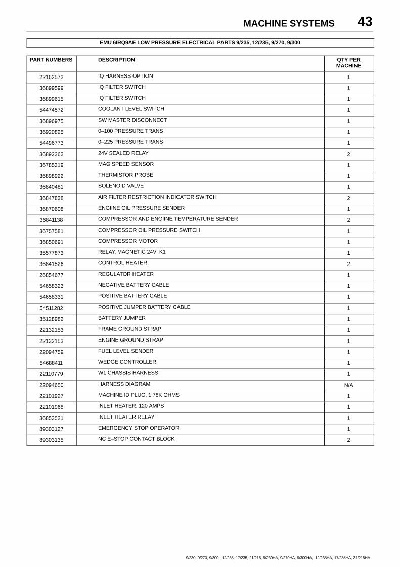
MACHINE SYSTEMS 43
9/230, 9/270, 9/300, 12/235, 17/235, 21/215, 9/230HA, 9/270HA, 9/300HA, 12/235HA, 17/235HA, 21/215HA
EMU 6IRQ9AE LOW PRESSURE ELECTRICAL PARTS 9/235, 12/235, 9/270, 9/300
PART NUMBERS DESCRIPTION QTY PERMACHINE
22162572 IQ HARNESS OPTION 1
36899599 IQ FILTER SWITCH 1
36899615 IQ FILTER SWITCH 1
54474572 COOLANT LEVEL SWITCH 1
36896975 SW MASTER DISCONNECT 1
36920825 0–100 PRESSURE TRANS 1
54496773 0–225 PRESSURE TRANS 1
36892362 24V SEALED RELAY 2
36785319 MAG SPEED SENSOR 1
36898922 THERMISTOR PROBE 1
36840481 SOLENOID VALVE 1
36847838 AIR FILTER RESTRICTION INDICATOR SWITCH 2
36870608 ENGIINE OIL PRESSURE SENDER 1
36841138 COMPRESSOR AND ENGIINE TEMPERATURE SENDER 2
36757581 COMPRESSOR OIL PRESSURE SWITCH 1
36850691 COMPRESSOR MOTOR 1
35577873 RELAY, MAGNETIC 24V K1 1
36841526 CONTROL HEATER 2
26854677 REGULATOR HEATER 1
54658323 NEGATIVE BATTERY CABLE 1
54658331 POSITIVE BATTERY CABLE 1
54511282 POSITIVE JUMPER BATTERY CABLE 1
35128982 BATTERY JUMPER 1
22132153 FRAME GROUND STRAP 1
22132153 ENGINE GROUND STRAP 1
22094759 FUEL LEVEL SENDER 1
54688411 WEDGE CONTROLLER 1
22110779 W1 CHASSIS HARNESS 1
22094650 HARNESS DIAGRAM N/A
22101927 MACHINE ID PLUG, 1.78K OHMS 1
22101968 INLET HEATER, 120 AMPS 1
36853521 INLET HEATER RELAY 1
89303127 EMERGENCY STOP OPERATOR 1
89303135 NC E–STOP CONTACT BLOCK 2
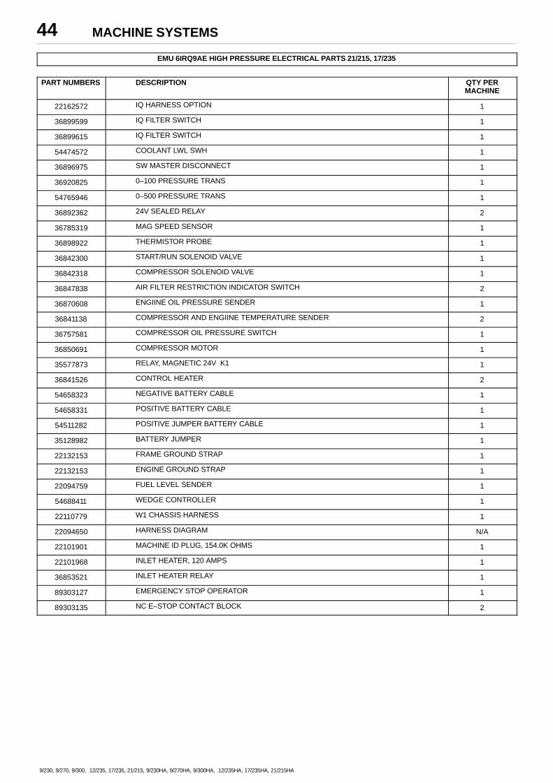
MACHINE SYSTEMS44
9/230, 9/270, 9/300, 12/235, 17/235, 21/215, 9/230HA, 9/270HA, 9/300HA, 12/235HA, 17/235HA, 21/215HA
EMU 6IRQ9AE HIGH PRESSURE ELECTRICAL PARTS 21/215, 17/235
PART NUMBERS DESCRIPTION QTY PERMACHINE
22162572 IQ HARNESS OPTION 1
36899599 IQ FILTER SWITCH 1
36899615 IQ FILTER SWITCH 1
54474572 COOLANT LWL SWH 1
36896975 SW MASTER DISCONNECT 1
36920825 0–100 PRESSURE TRANS 1
54765946 0–500 PRESSURE TRANS 1
36892362 24V SEALED RELAY 2
36785319 MAG SPEED SENSOR 1
36898922 THERMISTOR PROBE 1
36842300 START/RUN SOLENOID VALVE 1
36842318 COMPRESSOR SOLENOID VALVE 1
36847838 AIR FILTER RESTRICTION INDICATOR SWITCH 2
36870608 ENGIINE OIL PRESSURE SENDER 1
36841138 COMPRESSOR AND ENGIINE TEMPERATURE SENDER 2
36757581 COMPRESSOR OIL PRESSURE SWITCH 1
36850691 COMPRESSOR MOTOR 1
35577873 RELAY, MAGNETIC 24V K1 1
36841526 CONTROL HEATER 2
54658323 NEGATIVE BATTERY CABLE 1
54658331 POSITIVE BATTERY CABLE 1
54511282 POSITIVE JUMPER BATTERY CABLE 1
35128982 BATTERY JUMPER 1
22132153 FRAME GROUND STRAP 1
22132153 ENGINE GROUND STRAP 1
22094759 FUEL LEVEL SENDER 1
54688411 WEDGE CONTROLLER 1
22110779 W1 CHASSIS HARNESS 1
22094650 HARNESS DIAGRAM N/A
22101901 MACHINE ID PLUG, 154.0K OHMS 1
22101968 INLET HEATER, 120 AMPS 1
36853521 INLET HEATER RELAY 1
89303127 EMERGENCY STOP OPERATOR 1
89303135 NC E–STOP CONTACT BLOCK 2
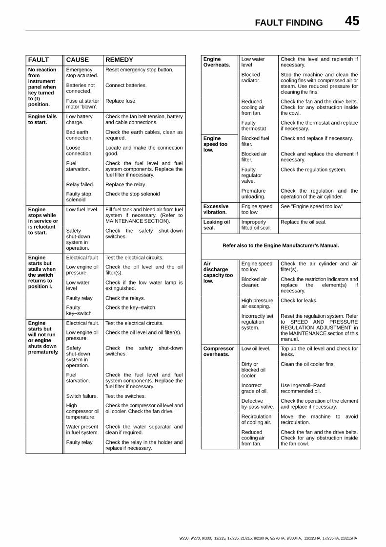
FAULT FINDING 45
9/230, 9/270, 9/300, 12/235, 17/235, 21/215, 9/230HA, 9/270HA, 9/300HA, 12/235HA, 17/235HA, 21/215HA
FAULT CAUSE REMEDYNo reactionfrom
Emergencystop actuated.
Reset emergency stop button.
instrumentpanel whenkey turned
Batteries notconnected.
Connect batteries.
to (I)position.
Fuse at startermotor ‘blown’.
Replace fuse.
Engine failsto start.
Low batterycharge.
Check the fan belt tension, batteryand cable connections.
Bad earthconnection.
Check the earth cables, clean asrequired.
Looseconnection.
Locate and make the connectiongood.
Fuelstarvation.
Check the fuel level and fuelsystem components. Replace thefuel filter if necessary.
Relay failed. Replace the relay.
Faulty stopsolenoid
Check the stop solenoid
Enginestops whilein service or
Low fuel level. Fill fuel tank and bleed air from fuelsystem if necessary. (Refer toMAINTENANCE SECTION).
is reluctantto start. Safety
shut-downsystem inoperation.
Check the safety shut-downswitches.
Engine Electrical fault Test the electrical circuits.starts butstalls whenthe switch
Low engine oilpressure.
Check the oil level and the oilfilter(s).the switch
returns toposition I.
Low waterlevel
Check if the low water lamp isextinguished.
Faulty relay Check the relays.
Faultykey–switch
Check the key–switch.
Engine Electrical fault. Test the electrical circuits.starts butwill not runor engine
Low engine oilpressure.
Check the oil level and oil filter(s).
or engineshuts downprematurely.
Safetyshut-downsystem inoperation.
Check the safety shut-downswitches.
Fuelstarvation.
Check the fuel level and fuelsystem components. Replace thefuel filter if necessary.
Switch failure. Test the switches.
Highcompressor oiltemperature.
Check the compressor oil level andoil cooler. Check the fan drive.
Water presentin fuel system.
Check the water separator andclean if required.
Faulty relay. Check the relay in the holder andreplace if necessary.
EngineOverheats.
Low waterlevel
Check the level and replenish ifnecessary.
Blockedradiator.
Stop the machine and clean thecooling fins with compressed air orsteam. Use reduced pressure forcleaning the fins.
Reducedcooling airfrom fan.
Check the fan and the drive belts.Check for any obstruction insidethe cowl.
Faultythermostat
Check the thermostat and replaceif necessary.
Enginespeed too
Blocked fuelfilter.
Check and replace if necessary.
low.Blocked airfilter.
Check and replace the element ifnecessary.
Faultyregulatorvalve.
Check the regulation system.
Prematureunloading.
Check the regulation and theoperation of the air cylinder.
Excessivevibration.
Engine speedtoo low.
See ”Engine speed too low”
Leaking oilseal.
Improperlyfitted oil seal.
Replace the oil seal.
Refer also to the Engine Manufacturer’s Manual.
Airdischarge
Engine speedtoo low.
Check the air cylinder and airfilter(s).
capacity toolow. Blocked air
cleaner.Check the restriction indicators andreplace the element(s) ifnecessary.
High pressureair escaping.
Check for leaks.
Incorrectly setregulationsystem.
Reset the regulation system. Referto SPEED AND PRESSUREREGULATION ADJUSTMENT inthe MAINTENANCE section of thismanual.
Compressoroverheats.
Low oil level. Top up the oil level and check forleaks.
Dirty orblocked oilcooler.
Clean the oil cooler fins.
Incorrectgrade of oil.
Use Ingersoll–Randrecommended oil.
Defectiveby-pass valve.
Check the operation of the elementand replace if necessary.
Recirculationof cooling air.
Move the machine to avoidrecirculation.
Reducedcooling airfrom fan.
Check the fan and the drive belts.Check for any obstruction insidethe fan cowl.
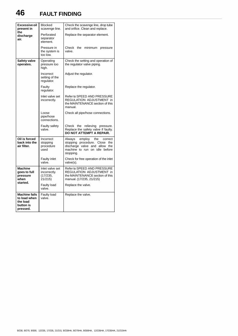
FAULT FINDING46
9/230, 9/270, 9/300, 12/235, 17/235, 21/215, 9/230HA, 9/270HA, 9/300HA, 12/235HA, 17/235HA, 21/215HA
Excessive oilpresent in
Blockedscavenge line.
Check the scavenge line, drop tubeand orifice. Clean and replace.
thedischargeair.
Perforatedseparatorelement.
Replace the separator element.
Pressure inthe system istoo low.
Check the minimum pressurevalve.
Safety valveoperates.
Operatingpressure toohigh.
Check the setting and operation ofthe regulator valve piping.
Incorrectsetting of theregulator.
Adjust the regulator.
Faultyregulator.
Replace the regulator.
Inlet valve setincorrectly.
Refer to SPEED AND PRESSUREREGULATION ADJUSTMENT inthe MAINTENANCE section of thismanual.
Loosepipe/hoseconnections.
Check all pipe/hose connections.
Faulty safetyvalve.
Check the relieving pressure.Replace the safety valve if faulty.DO NOT ATTEMPT A REPAIR.
Oil is forcedback into theair filter.
Incorrectstoppingprocedureused
Always employ the correctstopping procedure. Close thedischarge valve and allow themachine to run on idle beforestopping.
Faulty inletvalve.
Check for free operation of the inletvalve(s).
Machinegoes to fullpressurewhen
Inlet valve setincorrectly.(17/235,21/215)
Refer to SPEED AND PRESSUREREGULATION ADJUSTMENT inthe MAINTENANCE section of thismanual. (17/235, 21/215)
started.Faulty loadvalve.
Replace the valve.
Machine failsto load whenthe loadbutton ispressed.
Faulty loadvalve.
Replace the valve.
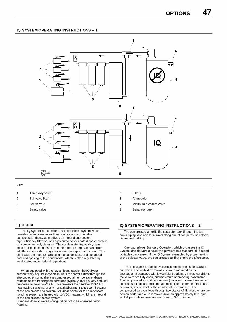
OPTIONS 47
9/230, 9/270, 9/300, 12/235, 17/235, 21/215, 9/230HA, 9/270HA, 9/300HA, 12/235HA, 17/235HA, 21/215HA
IQ SYSTEM OPERATING INSTRUCTIONS – 1
KEY
1 Three way valve
2 Ball valve11/4”
3 Ball valve2”
4 Safety valve
5 Filters
6 Aftercooler
7 Minimum pressure valve
8 Separator tank
IQ SYSTEM
The IQ System is a complete, self–contained system whichprovides cooler, cleaner air than from a standard portablecompressor. The system utilizes an integral aftercooler,high–efficiency filtration, and a patented condensate disposal systemto provide the cool, clean air. The condensate disposal systeminjects all liquid condensed from the moisture separator and filtersinto the engine exhaust system where it is vaporized by heat. Thiseliminates the need for collecting the condensate, and the addedcost of disposing of the condensate, which is often regulated bylocal, state, and/or federal regulations.
When equipped with the low ambient feature, the IQ Systemautomatically adjusts movable louvers to control airflow through theaftercooler, ensuring that the compressed air temperature alwaysremains above freezing temperatures (typically 45�F) at any ambienttemperature down to –20�F. This prevents the need for 120V ACheat tracing systems, or any manual adjustment to prevent freezingof the compressed air system. All drain points for the condensatehandling system are heated with 24VDC heaters, which are integralto the compressor heater system.Standard Non–Louvered configuration not to be operated belowfreezing.
IQ SYSTEM OPERATING INSTRUCTIONS – 2
The compressed air exits the separator tank through the topcover piping, and can then travel along one of two paths, selectablevia manual valving.
One path allows Standard Operation, which bypasses the IQSystem, and delivers air quality equivalent to a standard oil–floodedportable compressor. If the IQ System is enabled by proper settingof the selector valve, the compressed air first enters the aftercooler.
The aftercooler is cooled by the incoming compressor packageair, which is controlled by movable louvers mounted on theaftercooler (if equipped with low ambient option). At most conditions,the louvers are fully open, and maximum aftercooling is available.The compressed air and condensate (water with a small amount ofcompressor lubricant) exits the aftercooler and enters the moistureseparator, where most of the condensate is removed. Thecompressed air then flows through two stages of filtration, where theaerosol water and oil is removed down to approximately 0.01 ppm,and all particulates are removed down to 0.01 micron.
OPTIONS48
9/230, 9/270, 9/300, 12/235, 17/235, 21/215, 9/230HA, 9/270HA, 9/300HA, 12/235HA, 17/235HA, 21/215HA
At the bottom of the moisture separator and both filters arestrainers and constant–bleed orifices, which are sized to allow themaximum flow of condensate while minimizing compressed air loss.
The condensate lines are then piped together, and thecondensate is injected at a single point into the engine exhaustpiping. The compressed air then travels through the minimumpressure valve, and out through the service air valve. The airpressure gauge on the instrument panel indicates the pressureinside the separator tank. A service air pressure gauge is locatedinside the front door of the compressor on the filter support.
If the IQ System is bypassed (Standard Operation selected), thedelivered air pressure will be approximately equal to the separatortank pressure. If the IQ System operation is selected, the deliveredair pressure will be slightly less, depending on the restriction of thefilters.
Low Ambient Option Operation
When the ambient temperature falls to the point that theaftercooler outlet temperature is approaching 45�F, the TemperatureControl Unit (TCU), mounted on the rear of the control panel, willautomatically adjust the louvers to control the cooling airflow throughthe aftercooler.
In the event that the unit is operating under abnormal conditions(i.e., an enclosure door open) which would cause excessive coolingof the aftercooler, a temperature sensor in the aftercooler outletheader will signal the TCU to further close the louvers if thecompressed air temperature falls to approximately 36�F or lower.
There are no user selectable or serviceable components in theTCU. Contact Ingersoll–Rand Service if any abnormal operation ofthe freeze protection control system occurs.
MAINTENANCE
Daily Maintenance:
Verify, during full–load (maximum compressed air delivery) thatthe IQ System filter restriction indicators do not show excessiverestriction. Restriction indicators for the filters are mounted inside thecontrol panel, and will shut down the compressor if restrictionexceeds recommended values.
Weekly Maintenance:
� Remove Y–strainer screens at the bottom of the moistureseparator and both filters and clean out any residue.
� Verify that the orifices below the Y–strainers are not clogged.
� Verify that the piping from the orifice purge points to the exhaustsystem is not clogged.
Yearly Maintenance:
The normal maintenance interval on the primary and secondaryIQ System filters is one year, or earlier if pressure drop becomesexcessive. Restriction indicators for the filters are mounted on thefilter support inside the front door, and will shut down the compressorif restriction exceeds recommended values.
Filter Replacement
� With engine stopped, ensure pressure is relieved from airsystem.
� Remove all wires and hoses connected to drains on bottom ofeach filter housing. Inspect fittings and hoses for any blockage.Clean if necessary.
� Using a chain wrench or similar tool, loosen the housing. Thehousing should be removed by hand after loosening, taking care toprevent the housing from falling to the floor panel.
� Lower the housing to floor panel and lean it against the airend.Remove and replace the filter element, being careful not to damageouter wrap.
Verify the part number of new element vs. old element, as thetwo IQ filters are of different media.
OPTIONS – IQ SYSTEM
SAFETY
CAUTION: The compressor regulation system is adjusted to maintainregulated pressure at the separator tank. DO NOT adjust regulation toprovide full regulation pressure at the service valve when the IQSystem is enabled. This will result inC operation at excessivehorsepower levels, causing overheating, reduced engine life, andreduced airend life.
CAUTION: Excessively restricted filter elements may cause anincrease in the amount of aerosol water and oil carryover, which couldresult in damage to downstream equipment. Normal service intervalsshould not be exceeded.
CAUTION: Blockage of the condensate will result in flooding of thevessels. If flooding occurs, excessive condensate may enter the airstream and could result in damage to downstream equipment.
NOTICE:Do not operate at temperatures less that 2�C (35�F) unless equippedwith low ambient IQ option.
PARTS ORDERING 49
9/230, 9/270, 9/300, 12/235, 17/235, 21/215, 9/230HA, 9/270HA, 9/300HA, 12/235HA, 17/235HA, 21/215HA
GENERALThis publication, which contains an illustrated partsbreakdown, has been prepared as an aid in locatingthose parts which may be required in the maintenanceof the unit. All of the compressor parts, listed in theparts breakdown, are manufactured with the sameprecision as the original equipment. For the greatestprotection always insist on genuine Ingersoll–RandCompany parts for your compressor.
NOTICEIngersoll–Rand Company can bear no responsibility forinjury or damages resulting directly from the use ofnon–approved repair parts.
Ingersoll–Rand Company service facilities and partsare available worldwide. There are Ingersoll– RandCompany Construction Equipment Group SalesOffices and authorized distributors located in theprincipal cities of the United States. In Canada ourcustomers are serviced by the CanadianIngersoll–Rand Company, Limited. There are alsoIngersoll–Rand International autonomous companiesand authorized distributors located in the principal citiesthroughout the free world.
Special order parts may not be included in this manual.Contact the Mocksville Parts Department with the unitserial number for assistance with these special parts.
DESCRIPTIONThe illustrated parts breakdown illustrates and lists thevarious assemblies, subassemblies and detailed partswhich make up this particular machine. This covers thestandard models and the more popular options that areavailable.
A series of illustrations show each part distinctly and inlocation relative to the other parts in the assembly. Thepart number, the description of the part and the quantityof parts required are shown on each illustration or onadjacent page. The quantities specified are the numberof parts used per one assembly and are not necessarilythe total number of parts used in the machine. Whereno quantity is specified the quantity is assumed to beone.
Each description of a part is based upon the “noun first”method, i.e., the identifying noun or item name isalways the first part of the description. The noun nameis generally followed by a single descriptive modifier.The descriptive modifier may be followed by words orabbreviations such as upper, lower, inner, outer, front,rear, RH, LH, etc. when they are essential.
In referring to the rear, the front or to either side of theunit, always consider the drawbar end of the unit as thefront. Standing at the rear of the unit facing thedrawbar (front) will determine the right and left sides.
FASTENERSBoth SAE/inch, ISO/metric hardware have been usedin the design and assembly of these units. In thedisassembly and reassembly of parts, extreme caremust be taken to avoid damaging threads by the use ofwrong fasteners. In order to clarify the proper usageand for exact replacement parts, all standard fastenershave been identified by part number, size anddescription. This will enable a customer to obtainfasteners locally rather than ordering from the factory.These parts are identified in tables that will be found atthe rear of the parts illustrations. Any fastener that hasnot been identified by both part number and size is aspecially engineered part that must be ordered by partnumber to obtain the exact replacement part.
PARTS ORDERING50
9/230, 9/270, 9/300, 12/235, 17/235, 21/215, 9/230HA, 9/270HA, 9/300HA, 12/235HA, 17/235HA, 21/215HA
MARKINGS AND DECALS
NOTICEDo not paint over safety warnings or instructionaldecals. If safety warning decals become illegible,immediately order replacements from the factory.
Part numbers for original individual decals andtheir mounting locations are shown within PartsList Section. These are available as long as aparticular model is in production.
Afterwards, service sets of exterior decals and currentproduction safety warning decals are available.Contact the Product Support Group at Mocksville foryour particular needs and availability.
HOW TO USE PARTS LISTa. Turn to Parts List.
b. Locate the area or system of the compressor inwhich the desired part is used and find illustrationpage number.
c. Locate the desired part on the illustration by visualidentification and make note of part number anddescription.
HOW TO ORDERThe satisfactory ordering of parts by a purchaser isgreatly dependent upon the proper use of all availableinformation. By supplying your nearest sales office,autonomous company or authorized distributor, withcomplete information, you will enable them to fill yourorder correctly and to avoid any unnecessary delays.
In order that all avoidable errors may be eliminated, thefollowing instructions are offered as a guide to thepurchaser when ordering replacement parts:
a. Always specify the model number of the unit asshown on the general data decal attached to theunit.
b. Always specify the serial number of the unit. THISIS IMPORTANT. The serial number of the unit willbe found stamped on a plate attached to the unit.(The serial number on the unit is also permanentlystamped in the metal of the frame side rail.)
c. Always specify the number of the parts listpublication.
d. Always specify the quantity of parts required.
e. Always specify the part number, as well as thedescription of the part, or parts, exactly as it isgiven on the parts list illustration.
In the event parts are being returned to your nearestsales office, autonomous company or authorizeddistributor, for inspection or repair, it is important toinclude the serial number of the unit from which theparts were removed.
TERMS AND CONDITIONS ON PARTSORDERS
Acceptance: Acceptance of an offer is expresslylimited to the exact terms contained herein. Ifpurchaser’s order form is used for acceptance of anoffer, it is expressly understood and agreed that theterms and conditions of such order form shall not applyunless expressly agreed to by Ingersoll–RandCompany (“Company”) in writing. No additional orcontrary terms will be binding upon the Companyunless expressly agreed to in writing.
Taxes: Any tax or other governmental charge now orhereafter levied upon the production, sale, use orshipment of material and equipment ordered or sold isnot included in the Company’s price and will be chargedto and paid for by the Purchaser.
Shipping dates shall be extended for delays due to actsof God, acts of Purchaser, acts of Government, fires,floods, strikes, riot, war, embargo, transportationshortages, delay or default on the part of theCompany’s vendors, or any other cause beyond theCompany’s reasonable control.
Should Purchaser request special shipping instruction,such as exclusive use of shipping facilities, including airfreight when common carrier has been quoted andbefore change order to purchase order can be receivedby the Company, the additional charges will be honoredby the Purchaser.
Warranty: The Company warrants that partsmanufactured by it will be as specified and will be freefrom defects in materials and workmanship. TheCompany’s liability under this warranty shall be limitedto the repair or replacement of any part which wasdefective at the time of shipment provided Purchasernotifies the Company of any such defect promptly upondiscovery, but in no event later than three (3) monthsfrom the date of shipment of such part by the Company.The only exception to the previous statement is theextended warranty as it applies to the special airendexchange program.
Repairs and replacements shall be made by theCompany F.O.B. point of shipment. The Company shallnot be responsible for costs of transportation, removalor installation.
Warranties applicable to material and equipmentsupplied by the Company but wholly manufactured byothers shall be limited to the warranties extended to theCompany by the manufacturer which are able to beconveyed to the Purchaser.
Delivery: Shipping dates are approximate. TheCompany will use best efforts to ship by the datesspecified; however, the Company shall not be liable forany delay or failure in the estimated delivery orshipment of material and equipment or for anydamages suffered by reason thereof.
PARTS ORDERING 51
9/230, 9/270, 9/300, 12/235, 17/235, 21/215, 9/230HA, 9/270HA, 9/300HA, 12/235HA, 17/235HA, 21/215HA
The company makes no other warranty orrepresentation of any kind whatsoever, expressed orimplied, except that of title, and all implied warranties,including any warranty of merchantability and fitness fora particular purpose, are hereby disclaimed.
Limitation of Liability: The remedies of the Purchaser set forth herein areexclusive, and the total liability of the Company withrespect to this order whether based on contract,warranty, negligence, indemnity, strict liability orotherwise, shall not exceed the purchase price of thepart upon which such liability is based.
The Company shall in no event be liable to thePurchaser, any successors in interest or anybeneficiary of this order for any consequential,incidental, indirect, special or punitive damages arisingout of this order or any breach thereof, or any defect in,or failure of, or malfunction of the parts hereunder,whether based upon loss of use, lost profits or revenue,interest, lost goodwill, work stoppage, impairment ofother goods, loss by reason of shutdown or non–operation, increased expenses of operation or claims ofcustomers of Purchaser for service interruptionwhether or not such loss or damage is based oncontract, warranty, negligence, indemnity, strict liabilityor otherwise.
AIREND EXCHANGE PROGRAMIngersoll–Rand offers an airend exchange program tobenefit portable compressor users.
On the airend exchange program the exchange price isdetermined by the age and condition of the airend.
Your nearest sales office, autonomous company orauthorized distributor must first contact the PartsService Department at the factory at which yourportable air compressor was manufactured for anairend exchange number. The airend must be taggedwith this preassigned number and returned to thefactory prepaid. The airend must be intact, with noexcluded parts, otherwise the exchange agreementmay be cancelled. The warranty on an exchange orfactory rebuilt airend is 365 days.Airends being returned to the factory in connection witha WARRANTY CLAIM must be processed through theCustomer Service Department. If returned without aWarranty MRR (Material Return Request) Number, nowarranty claim will be considered.
PARTS ORDERING52
9/230, 9/270, 9/300, 12/235, 17/235, 21/215, 9/230HA, 9/270HA, 9/300HA, 12/235HA, 17/235HA, 21/215HA
For parts, service or information regarding your local U.S, Latin America or Asia Pacific distributor, please contact:
Ingersoll–Rand Company
501 Sanford Avenue
P.O. Box 868
Mocksville, N.C. 27028
Telephone:
800–633–5206 (US & Canada)
305–222–0835 (Latin America)
65–860–6863 (Asia Pacific)
Fax:
336–751–1579 (US & Canada)
336–751–4325 (Latin America)
336–751–4325 (Asia Pacific)
Facility:
Office hours: Monday – Friday 8:00 a.m. to 5:30 p.m. (EST)
Telephone: +44 (0) 1942 257 171
Fax: +44 (0) 1942 523 417
Facility:
Office hours: Monday – Friday 8:00 a.m. to 4:30 p.m. (GMT)
For information on how to order parts or information regarding your local distributor (Europe, Middle East, Africa) please contact:
Portable Power Aftermarket ESAIngersoll–Rand European Sales LtdSwan Lane, Hindley GreenWigan WN2 4 EZUnited Kingdom
Emergency order telephone # +44 (0) 777 617 0921


Printed in the United Kingdom


, 242[235], 243[236], 244[237] AND 285 [270] OF PRESIDENTIAL DECREE NO. 442, OTHERWISE KNOWN AS](https://img.pdfslide.us/doc/110x75/60e786ea7912195d7a4f45db/seventeenth-congress-of-the-republic-of-the-pdf-2016-9-27-240234c.jpg)