Embed Size (px)
DESCRIPTION
919
Citation preview
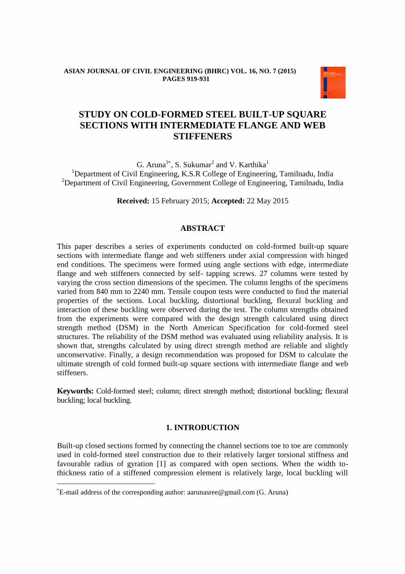
ASIAN JOURNAL OF CIVIL ENGINEERING (BHRC) VOL. 16, NO. 7 (2015)
PAGES 919-931
STUDY ON COLD-FORMED STEEL BUILT-UP SQUARE
SECTIONS WITH INTERMEDIATE FLANGE AND WEB
STIFFENERS
G. Aruna1, S. Sukumar2 and V. Karthika1 1Department of Civil Engineering, K.S.R College of Engineering, Tamilnadu, India
2Department of Civil Engineering, Government College of Engineering, Tamilnadu, India
Received: 15 February 2015; Accepted: 22 May 2015
ABSTRACT
This paper describes a series of experiments conducted on cold-formed built-up square
sections with intermediate flange and web stiffeners under axial compression with hinged
end conditions. The specimens were formed using angle sections with edge, intermediate
flange and web stiffeners connected by self- tapping screws. 27 columns were tested by
varying the cross section dimensions of the specimen. The column lengths of the specimens
varied from 840 mm to 2240 mm. Tensile coupon tests were conducted to find the material
properties of the sections. Local buckling, distortional buckling, flexural buckling and
interaction of these buckling were observed during the test. The column strengths obtained
from the experiments were compared with the design strength calculated using direct
strength method (DSM) in the North American Specification for cold-formed steel
structures. The reliability of the DSM method was evaluated using reliability analysis. It is
shown that, strengths calculated by using direct strength method are reliable and slightly
unconservative. Finally, a design recommendation was proposed for DSM to calculate the
ultimate strength of cold formed built-up square sections with intermediate flange and web
stiffeners.
Keywords: Cold-formed steel; column; direct strength method; distortional buckling; flexural
buckling; local buckling.
1. INTRODUCTION
Built-up closed sections formed by connecting the channel sections toe to toe are commonly
used in cold-formed steel construction due to their relatively larger torsional stiffness and
favourable radius of gyration [1] as compared with open sections. When the width to-
thickness ratio of a stiffened compression element is relatively large, local buckling will
E-mail address of the corresponding author: [email protected] (G. Aruna)
G. Aruna, S. Sukumar and V. Karthika
920
reduce the full strength of the member [2]. However, local buckling stress could be
enhanced by adding intermediate web stiffeners [3]. In this study, the cold-formed steel
built-up square sections with intermediate flange and web stiffeners are investigated.
Limited research is carried out on cold-formed built-up closed sections in the past years.
Young and Ju Chen [3] carried out a series of column tests on cold-formed steel built-up
closed sections with intermediate stiffeners. Jessica Whittle and Chris Ramseyer [4]
investigated the buckling capacities of axially loaded, cold formed built-up C channels. The
Evaluation of the slenderness ratio in built-up cold-formed box sections was investigated by
Wilson Reyes and Andres Guzmanc [5]. Design of built-up cold-formed steel columns
according to the direct strength method was presented by Georgieva et al. [6]. Experimental
and Numerical investigation was carried out on built-up- Z members under bending and
compression by Iveta Georgieva et al. [7]. There are not many test data reported on cold-
formed steel square sections with intermediate flange and web stiffeners.
In this paper, explains a series of experiments conducted on cold-formed steel built-up
square sections with intermediate flange and web stiffeners. The column strengths obtained
from the experiments were compared with the design strength calculated using direct
strength method in the North American Specification for cold-formed steel structures. The
reliability analysis was carried out to assess the reliability of the DSM. And also a design
recommendation was proposed to calculate the ultimate strength of cold-formed steel built-
up square sections with intermediate flange and web stiffeners.
2. EXPERIMENTAL INVESTIGATION
2.1 Specimens
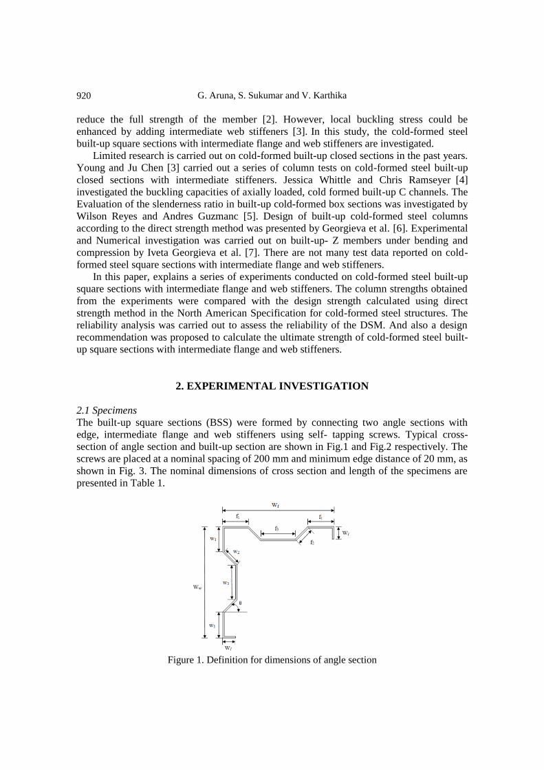
The built-up square sections (BSS) were formed by connecting two angle sections with
edge, intermediate flange and web stiffeners using self- tapping screws. Typical cross-
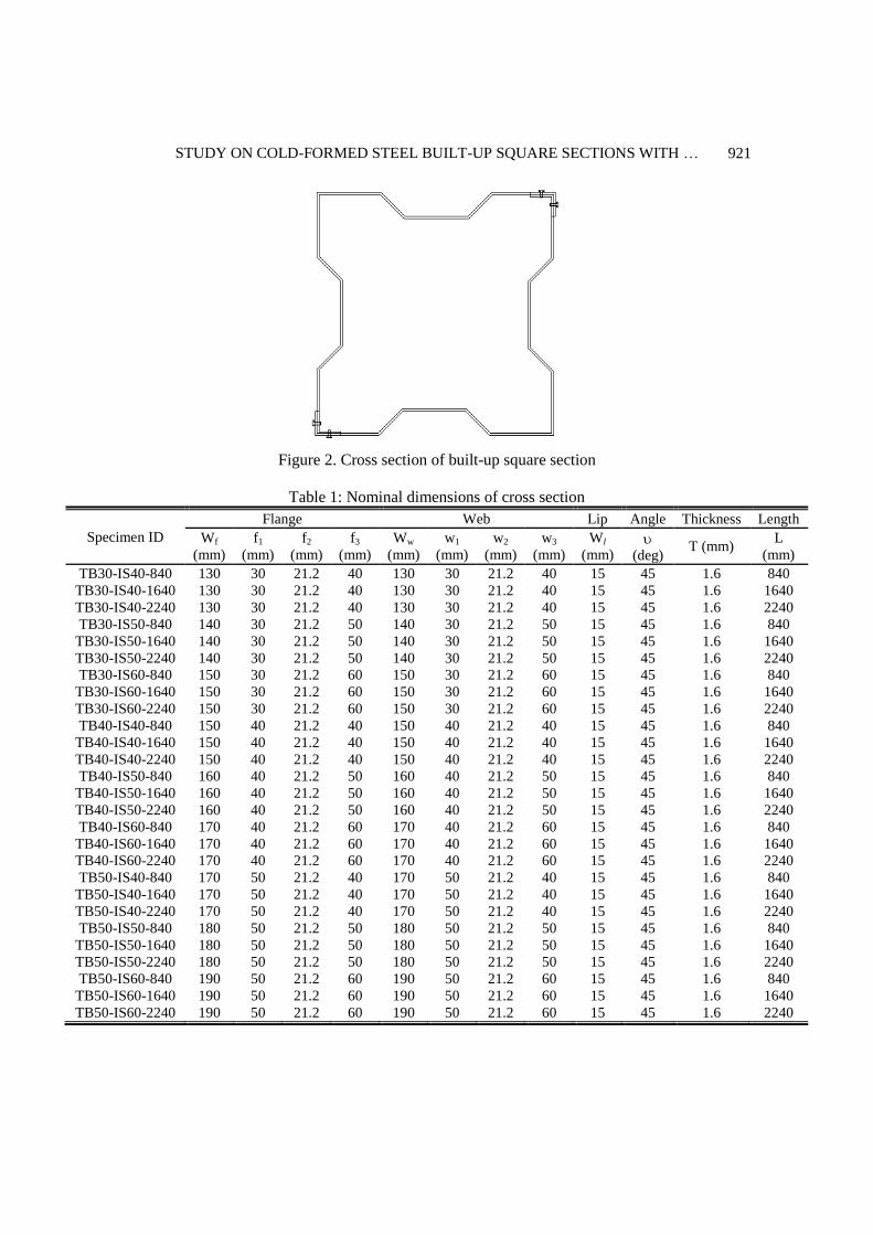
section of angle section and built-up section are shown in Fig.1 and Fig.2 respectively. The
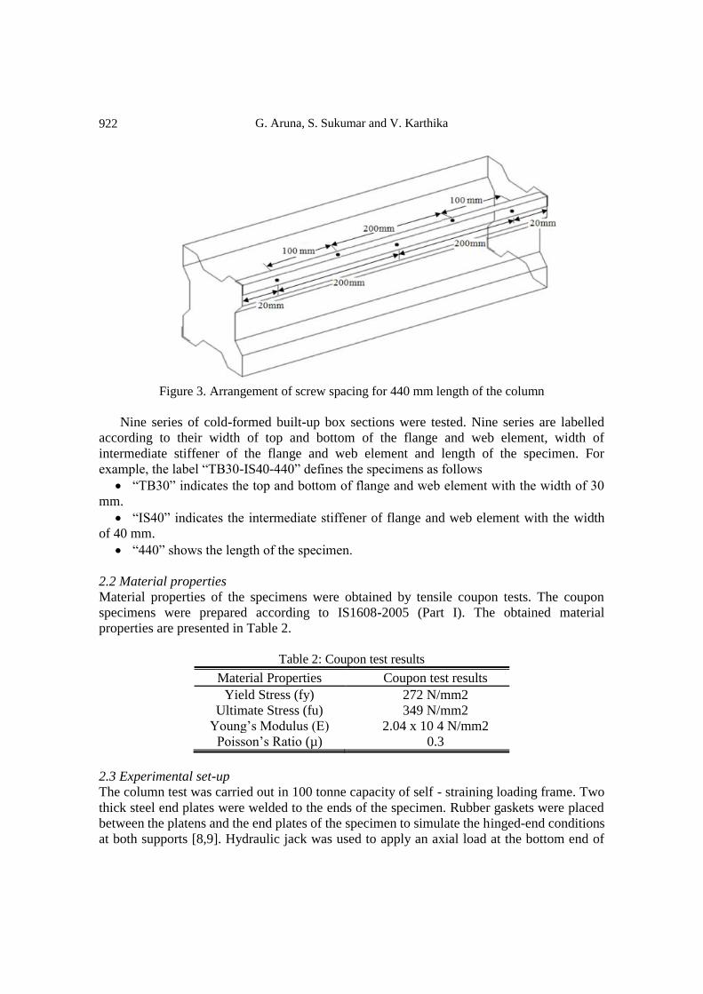
screws are placed at a nominal spacing of 200 mm and minimum edge distance of 20 mm, as
shown in Fig. 3. The nominal dimensions of cross section and length of the specimens are
presented in Table 1.
Figure 1. Definition for dimensions of angle section
STUDY ON COLD-FORMED STEEL BUILT-UP SQUARE SECTIONS WITH …
921
Figure 2. Cross section of built-up square section
Table 1: Nominal dimensions of cross section
Specimen ID
Flange Web Lip Angle Thickness Length
Wf
(mm)
f1
(mm)
f2
(mm)
f3
(mm)
Ww
(mm)
w1
(mm)
w2
(mm)
w3
(mm)
Wl
(mm)
(deg) T (mm)
L
(mm)
TB30-IS40-840 130 30 21.2 40 130 30 21.2 40 15 45 1.6 840
TB30-IS40-1640 130 30 21.2 40 130 30 21.2 40 15 45 1.6 1640
TB30-IS40-2240 130 30 21.2 40 130 30 21.2 40 15 45 1.6 2240
TB30-IS50-840 140 30 21.2 50 140 30 21.2 50 15 45 1.6 840
TB30-IS50-1640 140 30 21.2 50 140 30 21.2 50 15 45 1.6 1640
TB30-IS50-2240 140 30 21.2 50 140 30 21.2 50 15 45 1.6 2240
TB30-IS60-840 150 30 21.2 60 150 30 21.2 60 15 45 1.6 840
TB30-IS60-1640 150 30 21.2 60 150 30 21.2 60 15 45 1.6 1640
TB30-IS60-2240 150 30 21.2 60 150 30 21.2 60 15 45 1.6 2240
TB40-IS40-840 150 40 21.2 40 150 40 21.2 40 15 45 1.6 840
TB40-IS40-1640 150 40 21.2 40 150 40 21.2 40 15 45 1.6 1640
TB40-IS40-2240 150 40 21.2 40 150 40 21.2 40 15 45 1.6 2240
TB40-IS50-840 160 40 21.2 50 160 40 21.2 50 15 45 1.6 840
TB40-IS50-1640 160 40 21.2 50 160 40 21.2 50 15 45 1.6 1640
TB40-IS50-2240 160 40 21.2 50 160 40 21.2 50 15 45 1.6 2240
TB40-IS60-840 170 40 21.2 60 170 40 21.2 60 15 45 1.6 840
TB40-IS60-1640 170 40 21.2 60 170 40 21.2 60 15 45 1.6 1640
TB40-IS60-2240 170 40 21.2 60 170 40 21.2 60 15 45 1.6 2240
TB50-IS40-840 170 50 21.2 40 170 50 21.2 40 15 45 1.6 840
TB50-IS40-1640 170 50 21.2 40 170 50 21.2 40 15 45 1.6 1640
TB50-IS40-2240 170 50 21.2 40 170 50 21.2 40 15 45 1.6 2240
TB50-IS50-840 180 50 21.2 50 180 50 21.2 50 15 45 1.6 840
TB50-IS50-1640 180 50 21.2 50 180 50 21.2 50 15 45 1.6 1640
TB50-IS50-2240 180 50 21.2 50 180 50 21.2 50 15 45 1.6 2240
TB50-IS60-840 190 50 21.2 60 190 50 21.2 60 15 45 1.6 840
TB50-IS60-1640 190 50 21.2 60 190 50 21.2 60 15 45 1.6 1640
TB50-IS60-2240 190 50 21.2 60 190 50 21.2 60 15 45 1.6 2240
G. Aruna, S. Sukumar and V. Karthika
922
Figure 3. Arrangement of screw spacing for 440 mm length of the column
Nine series of cold-formed built-up box sections were tested. Nine series are labelled
according to their width of top and bottom of the flange and web element, width of
intermediate stiffener of the flange and web element and length of the specimen. For
example, the label “TB30-IS40-440” defines the specimens as follows
“TB30” indicates the top and bottom of flange and web element with the width of 30
mm.
“IS40” indicates the intermediate stiffener of flange and web element with the width
of 40 mm.
“440” shows the length of the specimen.
2.2 Material properties
Material properties of the specimens were obtained by tensile coupon tests. The coupon
specimens were prepared according to IS1608-2005 (Part I). The obtained material
properties are presented in Table 2.
Table 2: Coupon test results
Material Properties Coupon test results
Yield Stress (fy) 272 N/mm2
Ultimate Stress (fu) 349 N/mm2
Young’s Modulus (E) 2.04 x 10 4 N/mm2
Poisson’s Ratio (µ) 0.3
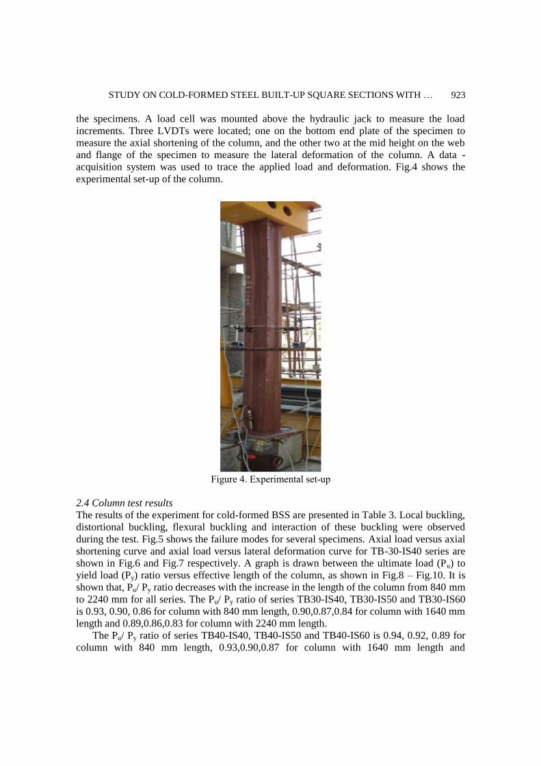
2.3 Experimental set-up
The column test was carried out in 100 tonne capacity of self - straining loading frame. Two
thick steel end plates were welded to the ends of the specimen. Rubber gaskets were placed
between the platens and the end plates of the specimen to simulate the hinged-end conditions
at both supports [8,9]. Hydraulic jack was used to apply an axial load at the bottom end of
STUDY ON COLD-FORMED STEEL BUILT-UP SQUARE SECTIONS WITH …
923
the specimens. A load cell was mounted above the hydraulic jack to measure the load
increments. Three LVDTs were located; one on the bottom end plate of the specimen to
measure the axial shortening of the column, and the other two at the mid height on the web
and flange of the specimen to measure the lateral deformation of the column. A data -
acquisition system was used to trace the applied load and deformation. Fig.4 shows the
experimental set-up of the column.
Figure 4. Experimental set-up
2.4 Column test results
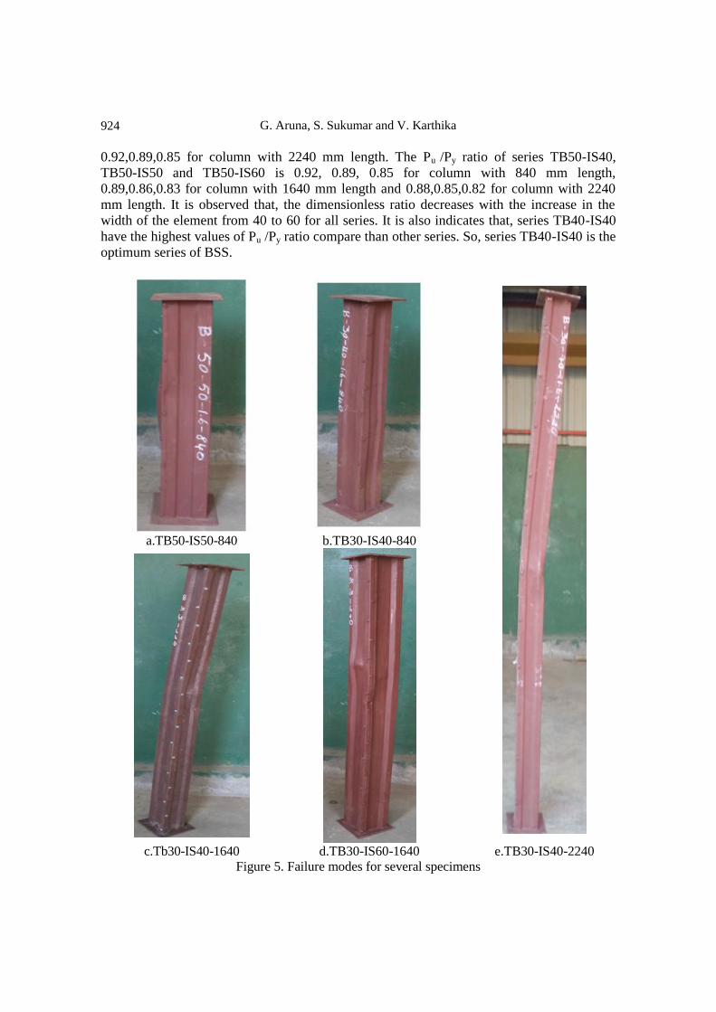
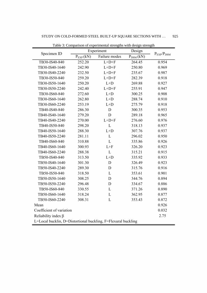
The results of the experiment for cold-formed BSS are presented in Table 3. Local buckling,
distortional buckling, flexural buckling and interaction of these buckling were observed
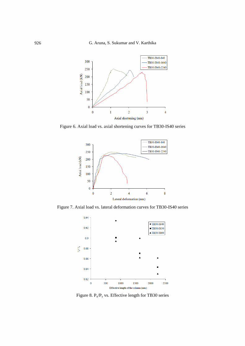
during the test. Fig.5 shows the failure modes for several specimens. Axial load versus axial
shortening curve and axial load versus lateral deformation curve for TB-30-IS40 series are
shown in Fig.6 and Fig.7 respectively. A graph is drawn between the ultimate load (Pu) to
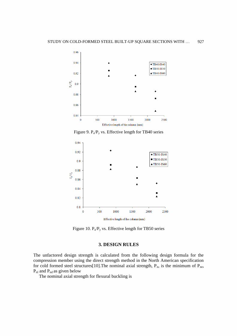
yield load (Py) ratio versus effective length of the column, as shown in Fig.8 – Fig.10. It is
shown that, Pu/ Py ratio decreases with the increase in the length of the column from 840 mm
to 2240 mm for all series. The Pu/ Py ratio of series TB30-IS40, TB30-IS50 and TB30-IS60
is 0.93, 0.90, 0.86 for column with 840 mm length, 0.90,0.87,0.84 for column with 1640 mm
length and 0.89,0.86,0.83 for column with 2240 mm length.
The Pu/ Py ratio of series TB40-IS40, TB40-IS50 and TB40-IS60 is 0.94, 0.92, 0.89 for
column with 840 mm length, 0.93,0.90,0.87 for column with 1640 mm length and
G. Aruna, S. Sukumar and V. Karthika
924
0.92,0.89,0.85 for column with 2240 mm length. The Pu /Py ratio of series TB50-IS40,
TB50-IS50 and TB50-IS60 is 0.92, 0.89, 0.85 for column with 840 mm length,
0.89,0.86,0.83 for column with 1640 mm length and 0.88,0.85,0.82 for column with 2240
mm length. It is observed that, the dimensionless ratio decreases with the increase in the
width of the element from 40 to 60 for all series. It is also indicates that, series TB40-IS40
have the highest values of Pu /Py ratio compare than other series. So, series TB40-IS40 is the
optimum series of BSS.
a.TB50-IS50-840 b.TB30-IS40-840
c.Tb30-IS40-1640 d.TB30-IS60-1640 e.TB30-IS40-2240
Figure 5. Failure modes for several specimens
STUDY ON COLD-FORMED STEEL BUILT-UP SQUARE SECTIONS WITH …
925
Table 3: Comparison of experimental strengths with design strength
Specimen ID Experiment Design
PEXP/PDSM PEXP (kN) Failure modes PDSM (kN)
TB30-IS40-840 252.20 L+D+F 264.45 0.954
TB30-IS40-1640 242.90 L+D+F 250.80 0.969
TB30-IS40-2240 232.50 L+D+F 235.67 0.987
TB30-IS50-840 259.20 L+D+F 282.39 0.918
TB30-IS50-1640 250.20 L+D 269.88 0.927
TB30-IS50-2240 242.40 L+D+F 255.91 0.947
TB30-IS60-840 272.60 L+D 300.25 0.908
TB30-IS60-1640 262.80 L+D 288.74 0.910
TB30-IS60-2240 253.19 L+D 275.79 0.918
TB40-IS40-840 286.30 D 300.35 0.953
TB40-IS40-1640 279.20 D 289.18 0.965
TB40-IS40-2240 270.00 L+D+F 276.60 0.976
TB40-IS50-840 298.20 L 318.13 0.937
TB40-IS50-1640 288.30 L+D 307.76 0.937
TB40-IS50-2240 281.11 L 296.02 0.950
TB40-IS60-840 310.88 L 335.86 0.926
TB40-IS60-1640 300.93 L+F 326.20 0.923
TB40-IS60-2240 288.38 L 315.21 0.915
TB50-IS40-840 313.50 L+D 335.92 0.933
TB50-IS40-1640 301.30 D 326.49 0.923
TB50-IS40-2240 289.30 D 315.76 0.916
TB50-IS50-840 318.50 L 353.61 0.901
TB50-IS50-1640 308.25 D 344.76 0.894
TB50-IS50-2240 296.48 D 334.67 0.886
TB50-IS60-840 330.55 L 371.26 0.890
TB50-IS60-1640 318.24 L 362.95 0.877
TB50-IS60-2240 308.31 L 353.43 0.872
Mean 0.926
Coefficient of variation 0.032
Reliability index 2.75
L=Local bucklin, D=Distortional buckling, F=Flexural buckling
G. Aruna, S. Sukumar and V. Karthika
926
Figure 6. Axial load vs. axial shortening curves for TB30-IS40 series
Figure 7. Axial load vs. lateral deformation curves for TB30-IS40 series
Figure 8. Pu/Py vs. Effective length for TB30 series
STUDY ON COLD-FORMED STEEL BUILT-UP SQUARE SECTIONS WITH …
927
Figure 9. Pu/Py vs. Effective length for TB40 series
Figure 10. Pu/Py vs. Effective length for TB50 series
3. DESIGN RULES
The unfactored design strength is calculated from the following design formula for the
compression member using the direct strength method in the North American specification
for cold formed steel structures[10].The nominal axial strength, Pn, is the minimum of Pne,
Pnl and Pnd as given below
The nominal axial strength for flexural buckling is
G. Aruna, S. Sukumar and V. Karthika
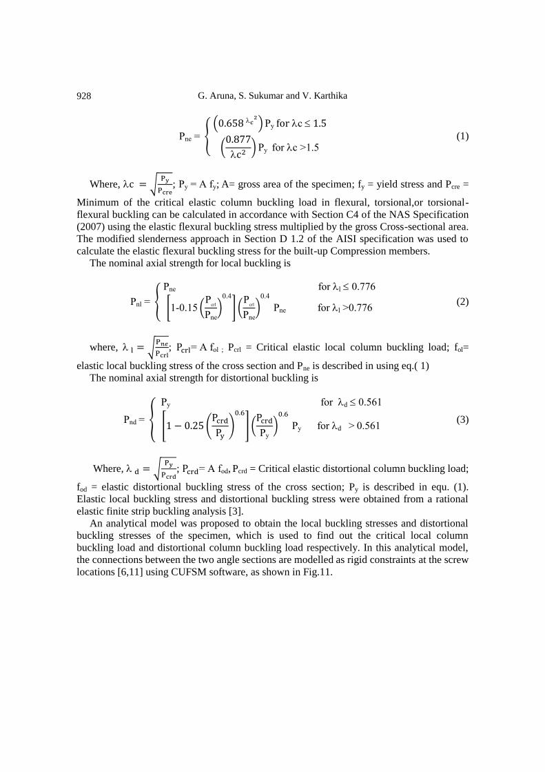
928
Pne { (
)P c
(
) P for c .
(1)
Where, √
; P f ; A= gross area of the specimen; fy = yield stress and Pcre =
Minimum of the critical elastic column buckling load in flexural, torsional,or torsional-
flexural buckling can be calculated in accordance with Section C4 of the NAS Specification
(2007) using the elastic flexural buckling stress multiplied by the gross Cross-sectional area.
The modified slenderness approach in Section D 1.2 of the AISI specification was used to
calculate the elastic flexural buckling stress for the built-up Compression members.
The nominal axial strength for local buckling is
Pnl {
Pne for l 0.
[ 0. (P
crl
Pne
)0.4
] (P
crl
Pne
)0.4
Pne for l 0. (2)
where, √
; fol ; Pcrl = Critical elastic local column buckling load; fol=
elastic local buckling stress of the cross section and Pne is described in using eq.( 1)
The nominal axial strength for distortional buckling is
Pnd {
P for d 0.
[ ( )
] ( P
)
P for d 0. (3)
Where, √
; fod, Pcrd = Critical elastic distortional column buckling load;
fod = elastic distortional buckling stress of the cross section; Py is described in equ. (1).
Elastic local buckling stress and distortional buckling stress were obtained from a rational
elastic finite strip buckling analysis [3].
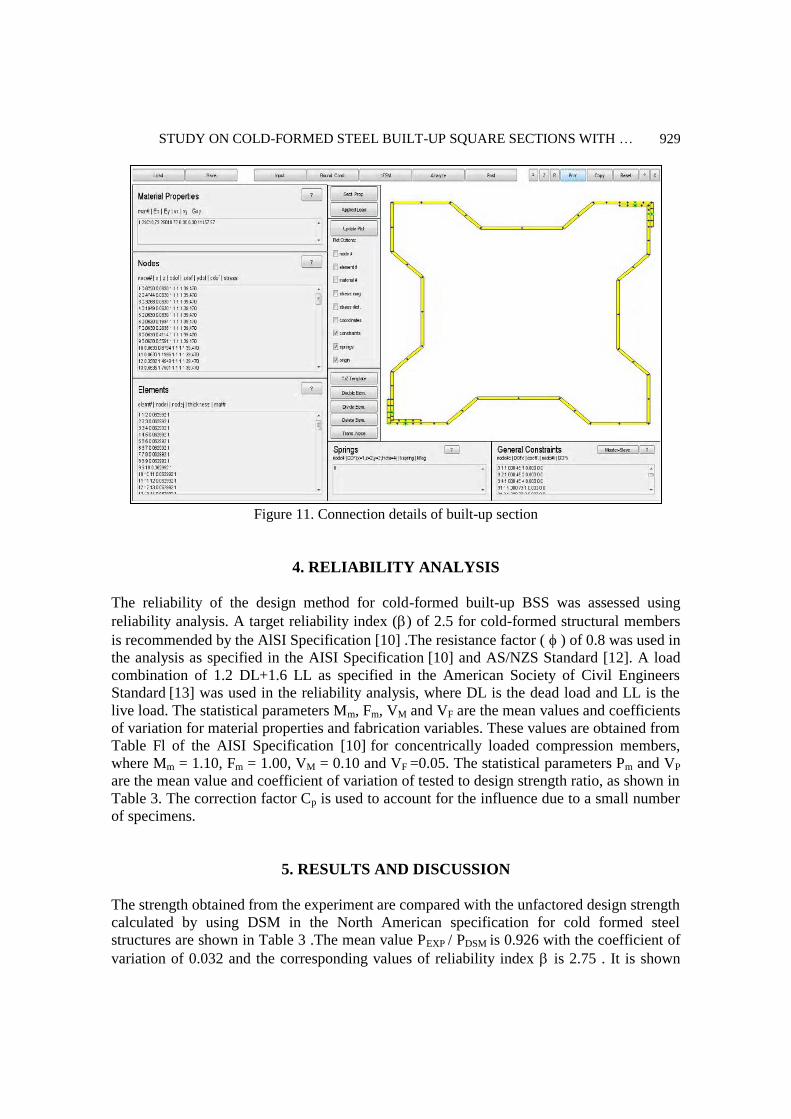
An analytical model was proposed to obtain the local buckling stresses and distortional
buckling stresses of the specimen, which is used to find out the critical local column
buckling load and distortional column buckling load respectively. In this analytical model,
the connections between the two angle sections are modelled as rigid constraints at the screw
locations [6,11] using CUFSM software, as shown in Fig.11.
STUDY ON COLD-FORMED STEEL BUILT-UP SQUARE SECTIONS WITH …
929
Figure 11. Connection details of built-up section
4. RELIABILITY ANALYSIS
The reliability of the design method for cold-formed built-up BSS was assessed using
reliability analysis. A target reliability index () of 2.5 for cold-formed structural members
is recommended by the AlSI Specification [10] .The resistance factor ( ) of 0.8 was used in
the analysis as specified in the AISI Specification [10] and AS/NZS Standard [12]. A load
combination of 1.2 DL+1.6 LL as specified in the American Society of Civil Engineers
Standard [13] was used in the reliability analysis, where DL is the dead load and LL is the
live load. The statistical parameters Mm, Fm, VM and VF are the mean values and coefficients
of variation for material properties and fabrication variables. These values are obtained from
Table Fl of the AISI Specification [10] for concentrically loaded compression members,
where Mm = 1.10, Fm = 1.00, VM = 0.10 and VF =0.05. The statistical parameters Pm and VP
are the mean value and coefficient of variation of tested to design strength ratio, as shown in
Table 3. The correction factor Cp is used to account for the influence due to a small number
of specimens.
5. RESULTS AND DISCUSSION
The strength obtained from the experiment are compared with the unfactored design strength
calculated by using DSM in the North American specification for cold formed steel
structures are shown in Table 3 .The mean value PEXP / PDSM is 0.926 with the coefficient of
variation of 0.032 and the corresponding values of reliability index is 2.75 . It is shown
G. Aruna, S. Sukumar and V. Karthika
930
that the reliability index is higher than the target value 2.5 of AISI [10]. So it is indicates
that design strengths calculated by using DSM are slightly unconservative but reliable.
6. DESIGN RECOMMENDATION
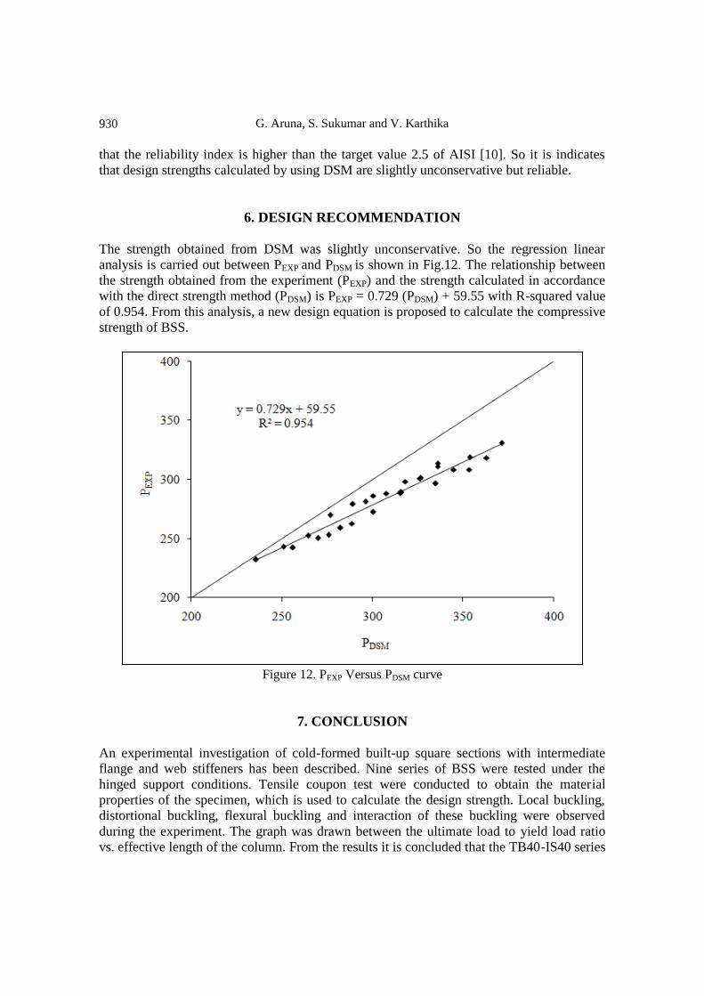
The strength obtained from DSM was slightly unconservative. So the regression linear
analysis is carried out between PEXP and PDSM is shown in Fig.12. The relationship between
the strength obtained from the experiment (PEXP) and the strength calculated in accordance
with the direct strength method (PDSM) is PEXP = 0.729 (PDSM) + 59.55 with R-squared value
of 0.954. From this analysis, a new design equation is proposed to calculate the compressive
strength of BSS.
Figure 12. PEXP Versus PDSM curve
7. CONCLUSION
An experimental investigation of cold-formed built-up square sections with intermediate
flange and web stiffeners has been described. Nine series of BSS were tested under the
hinged support conditions. Tensile coupon test were conducted to obtain the material
properties of the specimen, which is used to calculate the design strength. Local buckling,
distortional buckling, flexural buckling and interaction of these buckling were observed
during the experiment. The graph was drawn between the ultimate load to yield load ratio
vs. effective length of the column. From the results it is concluded that the TB40-IS40 series
STUDY ON COLD-FORMED STEEL BUILT-UP SQUARE SECTIONS WITH …
931
is stronger than other series. The strengths obtained from the experiment were compared
with the design strengths calculated using direct strength method in the North American
specifications for cold-formed steel structures. The appropriateness of the direct strength
method on BSS has been assessed by reliability analysis. It is shown that the reliability of
DSM is reliable and slightly unconservative. So, a new design equation was proposed to
calculate the ultimate compressive strength of BSS.
REFERENCES
1. Yu WW. Cold-Formed Steel Design, 3rd Ed, Wiley, New York, 2000.
2. Hancock GJ. Design of Cold-Formed Steel Structures, 3rd Ed, Australian Institute of
Steel Construction, Sydney, Australia, 1998.
3. Young B, Chen J. Design of cold-formed steel built-up closed sections with
intermediate stiffeners, Journal of Structural Engineering, ASCE, 134(2008) 727-37.
4. Whittle J, Ramseyer C. Buckling capacities of axially loaded, cold-formed, built-up C-
channels, Thin Walled Structures, 47(2009) 190-201.
5. Reyes W, Guzmanc A. Evaluation of the slenderness ratio in built-up cold-formed box
sections, Journal of Constructional Steel Research, 67(2011) 929-35.
6. Georgieva L, Schueremans L, Vandewalle L, Pyl L. Design of built-up cold-formed
steel columns according to the direct strength method, Steel Structures and Bridges,
40(2012) 119-24.
7. Georgieva I, Schueremans L, Pyl L. Experimental investigation of built-up double –Z
members in bending and compression, Thin Walled Structures, 53(2012) 48-57.
8. Sukumar S, Parameswaran P, Jayagopal LS. Local distortional and euler-buckling of
thin walled built-up open sections under compression, Journal of Structural
Engineering, SERC India, 32(2006) 447-54.
9. Anbarasu M, Sukumar S. Effect of connectors interaction in behaviour and ultimate
strength of intermediate length cold formed steel open columns, Asian Journal of Civil
Engineering, 14(2013) 305-17.
10. AISI-S100. North American Specification for the Design of Cold-Formed Steel
Structural Members Specifications, 2007.
11. Schafer B. Design Manual for Direct Strength Method of Cold-Formed Steel Design,
2002.
12. AS/NZS. Cold-formed Steel Structures, Sydney, Australia, New Zealand Standard,
AS/NZS 4600, Standards Australia, 2005.
13. ASCE. Minimum Design Loads for Buildings and Other Structures, ASCE/SEI 7-05,
American Society of Civil Engineers Standard, 2006.