Embed Size (px)
Citation preview

9140Dry-Well Calibrator
User’s Guide
January 2013© 2013 Fluke Corporation. All rights reserved. Specifications are subject to change without notice. All product names are trademarks of their respective companies.
PN 3729482


Table of Contents
1 Before You Start . . . . . . . . . . . . . . . . . . . . . . . . . . 11.1 Symbols Used . . . . . . . . . . . . . . . . . . . . . . . . . . . . 1
1.2 Safety Information . . . . . . . . . . . . . . . . . . . . . . . . . . 21.2.1 WARNINGS . . . . . . . . . . . . . . . . . . . . . . . . . . . . . . . . . . . 21.2.2 CAUTIONS . . . . . . . . . . . . . . . . . . . . . . . . . . . . . . . . . . . 4
1.3 Authorized Service Centers. . . . . . . . . . . . . . . . . . . . . . 5
2 Introduction . . . . . . . . . . . . . . . . . . . . . . . . . . . . 7
3 Specifications and Environmental Conditions . . . . . . . . . . 93.1 Specifications . . . . . . . . . . . . . . . . . . . . . . . . . . . . . 9
3.2 Environmental Conditions . . . . . . . . . . . . . . . . . . . . . . 9
3.3 Warranty . . . . . . . . . . . . . . . . . . . . . . . . . . . . . . . 10
4 Quick Start . . . . . . . . . . . . . . . . . . . . . . . . . . . . 114.1 Unpacking . . . . . . . . . . . . . . . . . . . . . . . . . . . . . . 11
4.2 Set-Up . . . . . . . . . . . . . . . . . . . . . . . . . . . . . . . . 11
4.3 Power . . . . . . . . . . . . . . . . . . . . . . . . . . . . . . . . 11
4.4 Setting the Temperature . . . . . . . . . . . . . . . . . . . . . . . 12
5 Parts and Controls . . . . . . . . . . . . . . . . . . . . . . . . 135.1 Rear Panel . . . . . . . . . . . . . . . . . . . . . . . . . . . . . . 13
5.2 Front Panel . . . . . . . . . . . . . . . . . . . . . . . . . . . . . 14
5.3 Constant Temperature Block Assembly . . . . . . . . . . . . . . . 155.3.1 Constant Temperature Block . . . . . . . . . . . . . . . . . . . . . . . . . . 155.3.2 Probe Sleeves and Tongs . . . . . . . . . . . . . . . . . . . . . . . . . . . . 15
6 General Operation . . . . . . . . . . . . . . . . . . . . . . . . 176.1 Calibrator Set-Up . . . . . . . . . . . . . . . . . . . . . . . . . . 17
6.2 Changing Display Units . . . . . . . . . . . . . . . . . . . . . . . 17
6.3 Switching to 230 V Operation. . . . . . . . . . . . . . . . . . . . 17
6.4 Setting the Temperature . . . . . . . . . . . . . . . . . . . . . . . 18
6.5 Calibrating Probes . . . . . . . . . . . . . . . . . . . . . . . . . . 18
7 Controller Operation . . . . . . . . . . . . . . . . . . . . . . . 217.1 Well Temperature . . . . . . . . . . . . . . . . . . . . . . . . . . 21
i

7.2 Temperature Set-point . . . . . . . . . . . . . . . . . . . . . . . . 217.2.1 Programmable Set-points . . . . . . . . . . . . . . . . . . . . . . . . . . . . 217.2.2 Set-point Value . . . . . . . . . . . . . . . . . . . . . . . . . . . . . . . . . 237.2.3 Temperature Scale Units . . . . . . . . . . . . . . . . . . . . . . . . . . . . 23
7.3 Scan . . . . . . . . . . . . . . . . . . . . . . . . . . . . . . . . . 247.3.1 Scan Control . . . . . . . . . . . . . . . . . . . . . . . . . . . . . . . . . . 247.3.2 Scan Rate . . . . . . . . . . . . . . . . . . . . . . . . . . . . . . . . . . . . 24
7.4 Temperature Display Hold . . . . . . . . . . . . . . . . . . . . . 257.4.1 Hold Temperature Display . . . . . . . . . . . . . . . . . . . . . . . . . . . 257.4.2 Mode Setting . . . . . . . . . . . . . . . . . . . . . . . . . . . . . . . . . . 257.4.3 Switch Wiring . . . . . . . . . . . . . . . . . . . . . . . . . . . . . . . . . . 257.4.4 Switch Test Example . . . . . . . . . . . . . . . . . . . . . . . . . . . . . . 26
7.5 Secondary Menu. . . . . . . . . . . . . . . . . . . . . . . . . . . 267.5.1 Heater Power . . . . . . . . . . . . . . . . . . . . . . . . . . . . . . . . . . 267.5.2 Proportional Band. . . . . . . . . . . . . . . . . . . . . . . . . . . . . . . . 27
7.6 Controller Configuration . . . . . . . . . . . . . . . . . . . . . . 297.6.1 Calibration Parameters . . . . . . . . . . . . . . . . . . . . . . . . . . . . . 29
7.6.1.1 R0 . . . . . . . . . . . . . . . . . . . . . . . . . . . . . . . . . . . . . . . . . . . . 297.6.1.2 ALPHA . . . . . . . . . . . . . . . . . . . . . . . . . . . . . . . . . . . . . . . . . 307.6.1.3 DELTA . . . . . . . . . . . . . . . . . . . . . . . . . . . . . . . . . . . . . . . . . 30
7.7 Operating Parameters . . . . . . . . . . . . . . . . . . . . . . . . 30
7.8 Serial Interface Parameters . . . . . . . . . . . . . . . . . . . . . 307.8.0.1 Baud Rate . . . . . . . . . . . . . . . . . . . . . . . . . . . . . . . . . . . . . . . . 30
7.8.1 Sample Period. . . . . . . . . . . . . . . . . . . . . . . . . . . . . . . . . . 317.8.1.1 Duplex Mode . . . . . . . . . . . . . . . . . . . . . . . . . . . . . . . . . . . . . . 317.8.1.2 Linefeed . . . . . . . . . . . . . . . . . . . . . . . . . . . . . . . . . . . . . . . . . 32
8 Digital Communication Interface . . . . . . . . . . . . . . . . 338.1 Serial Communications . . . . . . . . . . . . . . . . . . . . . . . 33
8.1.1 Wiring . . . . . . . . . . . . . . . . . . . . . . . . . . . . . . . . . . . . . . 338.1.2 Setup . . . . . . . . . . . . . . . . . . . . . . . . . . . . . . . . . . . . . . 33
8.1.2.1 Baud Rate . . . . . . . . . . . . . . . . . . . . . . . . . . . . . . . . . . . . . . . . 348.1.2.2 Sample Period. . . . . . . . . . . . . . . . . . . . . . . . . . . . . . . . . . . . . . 348.1.2.3 Duplex Mode . . . . . . . . . . . . . . . . . . . . . . . . . . . . . . . . . . . . . . 348.1.2.4 Linefeed . . . . . . . . . . . . . . . . . . . . . . . . . . . . . . . . . . . . . . . . . 34
8.1.3 Serial Operation . . . . . . . . . . . . . . . . . . . . . . . . . . . . . . . . . 34
8.2 Interface Commands . . . . . . . . . . . . . . . . . . . . . . . . 35
9 Test Probe Calibration . . . . . . . . . . . . . . . . . . . . . . 399.1 Comparison Methods . . . . . . . . . . . . . . . . . . . . . . . . 39
9.1.1 Calibrating a Single Probe . . . . . . . . . . . . . . . . . . . . . . . . . . . 399.1.2 Comparison Calibration. . . . . . . . . . . . . . . . . . . . . . . . . . . . . 399.1.3 Calibration of Multiple Probes . . . . . . . . . . . . . . . . . . . . . . . . . 40
9.2 Dry-well Characteristics. . . . . . . . . . . . . . . . . . . . . . . 409.2.1 Vertical Gradient . . . . . . . . . . . . . . . . . . . . . . . . . . . . . . . . 409.2.2 Heating and Cooling Rates . . . . . . . . . . . . . . . . . . . . . . . . . . . 409.2.3 Stabilization and Accuracy . . . . . . . . . . . . . . . . . . . . . . . . . . . 41
ii

10 Calibration Procedure . . . . . . . . . . . . . . . . . . . . . . 4310.1 Calibration Points . . . . . . . . . . . . . . . . . . . . . . . . . . 43
10.2 Calibration Procedure . . . . . . . . . . . . . . . . . . . . . . . . 4310.2.1 Compute DELTA: . . . . . . . . . . . . . . . . . . . . . . . . . . . . . . . . 4310.2.2 Compute R0 & ALPHA: . . . . . . . . . . . . . . . . . . . . . . . . . . . . . 4410.2.3 Accuracy & Repeatability. . . . . . . . . . . . . . . . . . . . . . . . . . . . 45
11 Maintenance . . . . . . . . . . . . . . . . . . . . . . . . . . . 47
12 Troubleshooting. . . . . . . . . . . . . . . . . . . . . . . . . . 4912.1 Troubleshooting Problems, Possible Causes, and Solutions . . . . 49
12.2 CE Comments . . . . . . . . . . . . . . . . . . . . . . . . . . . . 5012.2.1 EMC Directive . . . . . . . . . . . . . . . . . . . . . . . . . . . . . . . . . 5012.2.2 Low Voltage Directive (Safety) . . . . . . . . . . . . . . . . . . . . . . . . . 50
iii

iv
Figures
Figure 1 9140 Back Panel . . . . . . . . . . . . . . . . . . . . . . . . . . . . . 13Figure 2 9140 Front Panel . . . . . . . . . . . . . . . . . . . . . . . . . . . . . 14Figure 3 Inserts available for the 9140 block assembly . . . . . . . . . . . . . . 15Figure 4 Controller Operation Flowchart . . . . . . . . . . . . . . . . . . . . . 22Figure 5 Well temperature fluctuation at various proportional band settings . . . 27Figure 6 Serial Cable Wiring . . . . . . . . . . . . . . . . . . . . . . . . . . . 33Figure 7 Typical Heating Rate . . . . . . . . . . . . . . . . . . . . . . . . . . . 41Figure 8 Typical Cooling Rate. . . . . . . . . . . . . . . . . . . . . . . . . . . 41

v
Tables
Table 1 International Electrical Symbols . . . . . . . . . . . . . . . . . . . . . 1Table 2 9140 controller communications commands. . . . . . . . . . . . . . . 36Table 3 9140 controller communications commands continued . . . . . . . . . 37


1 Before You Start
1.1 Symbols UsedTable 1 lists the symbols used on the instrument or in this manual and themeaning of each symbol.
Symbol Description
AC (Alternating Current)
AC-DC
Battery
Complies with European Union directives
DC
Double Insulated
Electric Shock
Fuse
PE Ground
Hot Surface (Burn Hazard)
Read the User’s Manual (Important Information)
Off
On
1
1 Before You StartSymbols Used
Table 1 International Electrical Symbols

Symbol Description
Canadian Standards Association
OVERVOLTAGE (Installation) CATEGORY II, Pollution Degree 2 per IEC1010-1 re-fers to the level of Impulse Withstand Voltage protection provided. Equipment ofOVERVOLTAGE CATEGORY II is energy-consuming equipment to be supplied fromthe fixed installation. Examples include household, office, and laboratory appliances.
C-TIC Australian EMC
The European Waste Electrical and Electronic Equipment (WEEE) Directive(2002/96/EC) mark.
1.2 Safety InformationUse the instrument only as specified in this manual. Otherwise, the protectionprovided by the instrument may be impaired. Refer to the safety informationbelow and throughout the manual.
The following definitions apply to the terms “Warning” and “Caution”.
• “Warning” identifies conditions and actions that may pose hazards to theuser.
• “Caution” identifies conditions and actions that may damage the instru-ment being used.
1.2.1 WARNINGSTo avoid personal injury, follow these guidelines.
GENERAL
• DO NOT use this instrument in environments other than those listed inthe User’s Guide.
• Inspect the instrument for damage before each use. DO NOT use the in-strument if it appears damaged or operates abnormally.
• Follow all safety guidelines listed in the user’s manual.
• Calibration Equipment should only be used by Trained Personnel.
• If this equipment is used in a manner not specified by the manufacturer,the protection provided by the equipment may be impaired.
• Before initial use, or after transport, or after storage in humid or semi-hu-mid environments, or anytime the dry-well has not been energized formore than 10 days, the instrument needs to be energized for a "dry-out"period of 2 hours before it can be assumed to meet all of the safety re-quirements of the IEC 1010-1. If the product is wet or has been in a wetenvironment, take necessary measures to remove moisture prior to apply-
9140 Dry-well CalibratorUser’s Guide
2

ing power such as storage in a low humidity temperature chamber operat-ing at 50°C for 4 hours or more.
• DO NOT use this instrument for any application other than calibrationwork. The instrument was designed for temperature calibration. Any otheruse of the instrument may cause unknown hazards to the user.
• Completely unattended operation is not recommended.
• Overhead clearance is required. DO NOT place the instrument under acabinet or other structure. Always leave enough clearance to allow forsafe and easy insertion and removal of probes.
• If the instrument is used in a manner not in accordance with the equip-ment design, the operation of the dry-well may be impaired or safety haz-ards may arise.
• This instrument is intended for indoor use only.
BURN HAZARDS
• DO NOT turn the instrument upside down with the inserts in place; theinserts will fall out.
• DO NOT operate near flammable materials.
• Use of this instrument at HIGH TEMPERATURES for extended periodsof time requires caution.
• DO NOT touch the well access surface of the instrument.
• The block vent may be very hot due to the fan blowing across the heaterblock of the dry-well.
• The temperature of the well access is the same as the actual display tem-perature, e.g. if the instrument is set to 700°C and the display reads700°C, the well is at 700°C.
• For top loading dry-wells, the top sheet metal of the dry-well may exhibitextreme temperatures for areas close to the well access.
• The air over the well can reach temperatures greater that 200°C for hightemperature (400°C and higher) dry-wells. Note: Probes and inserts maybe hot and should only be inserted and removed from the instrumentwhen the instrument is set at temperatures less than 50°C. Use extremecare when removing hot inserts.
• DO NOT turn off the instrument at temperatures higher than 100°C. Thiscould create a hazardous situation. Select a set-point less than 100°C andallow the instrument to cool before turning it off.
• The high temperatures present in dry-wells designed for operation at300°C and higher may result in fires and severe burns if safety precau-tions are not observed.
• For compliance with IEC 1010-1, it is recommended that the cutout modealways be set to the manual mode requiring user intervention to reset theinstrument.
3
1 Before You StartSafety Information

ELECTRICAL SHOCK
• These guidelines must be followed to ensure that the safety mechanismsin this instrument will operate properly. This instrument must be pluggedinto a 115 VAC, 60Hz (230 VAC, 50Hz optional), AC only electric outlet.The power cord of the instrument is equipped with a three-prongedgrounding plug for your protection against electrical shock hazards. Itmust be plugged directly into a properly grounded three-prong receptacle.The receptacle must be installed in accordance with local codes and ordi-nances. Consult a qualified electrician. DO NOT use an extension cord oradapter plug.
• If supplied with user accessible fuses, always replace the fuse with one ofthe same rating, voltage, and type.
• Always replace the power cord with an approved cord of the correct rat-ing and type.
• HIGH VOLTAGE is used in the operation of this equipment. SEVEREINJURY or DEATH may result if personnel fail to observe safety precau-tions. Before working inside the equipment, turn power off and discon-nect power cord.
1.2.2 CAUTIONS• Always operate this instrument at room temperature between 41°F and
122°F (5°C to 50°C). Allow sufficient air circulation by leaving at least 6inches (15 cm) of clearance around the instrument. Overhead clearance isrequired. DO NOT place unit under any structure.
• Component lifetime can be shortened by continuous high temperature op-eration.
• DO NOT leave the sleeve(s) in the instrument for prolonged periods. Dueto the high operating temperatures of the instrument, the sleeves should beremoved after each use and buffed with a Scotch-Brite® pad or emerycloth. (See Maintenance, Section .)
• DO NOT apply any type of voltage to the display hold terminals. Apply-ing a voltage to the terminals may cause damage to the controller.
• DO NOT use fluids to clean out the well. Fluids could leak into electron-ics and damage the instrument.
• Never introduce any foreign material into the probe hole of the insert.Fluids, etc. can leak into the instrument causing damage.
• DO NOT change the values of the calibration constants from the factoryset values. The correct setting of these parameters is important to thesafety and proper operation of the calibrator.
• DO NOT slam the probe sheath in to the well. This type of action cancause a shock to the sensor and affect the calibration.
9140 Dry-well CalibratorUser’s Guide
4

• The instrument and any thermometer probes used with it are sensitive in-struments that can be easily damaged. Always handle these devices withcare. DO NOT allow them to be dropped, struck, stressed, or overheated.
• The Factory Reset Sequence (see Section 12.1, Troubleshooting) shouldbe performed only by authorized personnel if no other action is successfulin correcting a malfunction. You must have a copy of the most recent Re-port of Calibration to restore the calibration parameters.
• DO NOT operate this instrument in an excessively wet, oily, dusty, ordirty environment. Always keep the well and inserts clean and clear offoreign material.
• The dry-well is a precision instrument. Although it has been designed foroptimum durability and trouble free operation, it must be handled withcare. Always carry the instrument in an upright position to prevent theprobe sleeves from dropping out. The convenient handle allows for handcarrying the instrument.
• If a mains supply power fluctuation occurs, immediately turn off the in-strument. Power bumps from brown-outs could damage the instrument.Wait until the power has stabilized before re-energizing the instrument.
• The probe and the block may expand at different rates. Allow for probeexpansion inside the well as the block heats. Otherwise, the probe maybecome stuck in the well.
• Most probes have handle temperature limits. Be sure that the probe handletemperature limit is not exceeded in the air above the instrument. If theprobe handle limits are exceeded, the probe may be permanently dam-aged.
1.3 Authorized Service CentersPlease contact one of the following authorized Service Centers to coordinateservice on your Hart product:
Fluke Corporation, Hart Scientific Division
799 E. Utah Valley Drive
American Fork, UT 84003-9775
USA
Phone: +1.801.763.1600
Telefax: +1.801.763.1010
E-mail: [email protected]
Fluke Nederland B.V.
Customer Support Services
5
1 Before You StartAuthorized Service Centers

Science Park Eindhoven 5108
5692 EC Son
NETHERLANDS
Phone: +31-402-675300
Telefax: +31-402-675321
E-mail: [email protected]
Fluke Int'l Corporation
Service Center - Instrimpex
Room 2301 Sciteck Tower
22 Jianguomenwai Dajie
Chao Yang District
Beijing 100004, PRC
CHINA
Phone: +86-10-6-512-3436
Telefax: +86-10-6-512-3437
E-mail: [email protected]
Fluke South East Asia Pte Ltd.
Fluke ASEAN Regional Office
Service Center
60 Alexandra Terrace #03-16
The Comtech (Lobby D)
118502
SINGAPORE
Phone: +65 6799-5588
Telefax: +65 6799-5588
E-mail: [email protected]
When contacting these Service Centers for support, please have the followinginformation available:
• Model Number
• Serial Number
• Voltage
• Complete description of the problem
9140 Dry-well CalibratorUser’s Guide
6

2 Introduction
The Hart Scientific 9140 Mid-Range Field Calibrator may be used as a portableinstrument or bench top temperature calibrator for calibrating thermocoupleand RTD temperature probes. The 9140 is small enough to use in the field, andaccurate enough to use in the lab.
The instrument features:
• Rapid heating and cooling
• Interchangeable multiple hole aluminum probe sleeves
• Convenient hand strap
• RS-232 interface capability
Built in programmable features include:
• Temperature scan rate control
• Temperature switch hold
• Eight Setpoint memory
• Adjustable readout in °C or °F
The temperature is accurately controlled by Hart’s hybrid analog/digital con-troller. The controller uses a precision platinum RTD as a sensor and controlsthe well temperature with a solid state relay (triac) driven heater.
The LED front panel continuously shows the current well temperature. Thetemperature may be easily set with the control buttons to any desired tempera-ture within the specified range. The instrument’s multiple fault protection de-vices insure user and instrument safety and protection.
The 9140 dry-well calibrator was designed for portability, low cost, and ease ofoperation. Through proper use the instrument will provide continued accuratecalibration of temperature sensors and devices. The user should be familiarwith the safety guidelines and operating procedures of the calibrator as de-scribed in the instruction manual.
7
2 Introduction


3 Specifications and EnvironmentalConditions
3.1 SpecificationsThe following table lists the specifications for this instrument. Accuracy speci-fications are applicable for a one-year calibration interval. In line with normalprudent metrology practices, Hart Scientific recommends a short-cycle intervalof six months for new units during the first year.
Power 115 VAC (±10%), 4.4 A or 230 VAC (±10%), 2.2 A, switchable 500 W
Ambient Temperature 5–50°C (41–122°F)
Operating Range 35–350°C (95–662°F)
Resolution 0.1°C or °F resolution
Readout Switchable°C or °F
Accuracy ±0.5°C (±0.9°F), in holes greater than 1/4" (6.35 mm) accuracy is ±1°C(±1.8°F)
Stability ±0.03°C at 50°C, ±0.05°C at 350°C
Uniformity ±0.4°C typical, ±0.1°C with similarly sized wells
Controller Digital controller with data retention
Heater 500W
Heating Time 12 minutes from ambient to 350°C
Cooling Time 15 minutes from 350°C to 100°C
Cooling 2 speed internal fan
Stabilization Time 7 minutes
Immersion Depth 124 mm (4.88 inches)
Fault Protection Sensor burnout and short protection, over temperature thermal cut-out, elec-trical fuses
Test Wells 31.8 mm dia. x 123.7 mm deep (1.25" x 4.87"). Multi-hole inserts areavailable.
Exterior Dimension 152.4 mm H x 85.7 mm W x 196.9 mm D (6" x 3.375" x 7.75")
Weight 2.7 kg (6 lbs.)
Fuse Rating 115 V: 6 A (fast acting), 250 V230 V: 3.15 A (fast acting), 250 V
Safety OVERVOLTAGE (Installation) CATEGORY II, Pollution Degree 2 perIEC1010-1
3.2 Environmental ConditionsAlthough the instrument has been designed for optimum durability and trou-ble-free operation, it must be handled with care. The instrument should not be
9
3 Specifications and Environmental ConditionsSpecifications


4 Quick Start
4.1 UnpackingUnpack the dry-well carefully and inspect it for any damage that may have oc-curred during shipment. If there is shipping damage, notify the carrierimmediately.
Verify that the following components are present:
• 9140 Dry-well
• Insert
• Insert Removal Tool
• Power Cord
• Serial Cable
• User's Guide
• 9930 Software Package
4.2 Set-UpPlace the calibrator on a flat surface with at least 6 inches of free space aroundthe instrument. Plug the power cord into a grounded mains outlet. Observe thatthe nominal voltage corresponds to that indicated on the back of the calibrator.
Carefully insert the probe sleeve into the well. Probe sleeves should be of thesmallest hole diameter possible still allowing the probe to slide in and out eas-ily. Sleeves of various sizes are available from Hart Scientific. The well must beclear of any foreign objects, dirt and grit before the sleeve is inserted. Thesleeve is inserted with the two small tong holes positioned upward.
Turn on the power to the calibrator by toggling the switch on the power entrymodule. The fan should begin quietly blowing air through the instrument andthe controller display should illuminate after 3 seconds. After a brief self testthe controller should begin normal operation. If the unit fails to operate pleasecheck the power connection.
The display will begin to show the well temperature and the well heater willstart operating to bring the temperature of the well to the set-point temperature.After using the calibrator, allow the well to cool by setting the temperature to25°C and waiting for the instrument to reach temperature before turning the in-strument off.
4.3 PowerPlug the dry-well power cord into a mains outlet of the proper voltage, fre-quency, and current capability. Refer to Section 3.1, Specifications, for powerdetails. Turn the dry-well on using the rear panel “POWER” switch. The
11
4 Quick StartUnpacking

dry-well will turn on and begin to heat to the previously programmed tempera-ture set-point. The front panel LED display will indicate the actual dry-welltemperature.
4.4 Setting the TemperatureSection 7.2 explains in detail how to set the temperature set-point on the cali-brator using the front panel keys. The procedure is summarized here.
(1) Press “SET” twice to access the set-point value.
(2) Press “UP” or “DOWN” to change the set-point value.
(3) Press “SET” to program in the new set-point.
(4) Press “EXIT” to return to the temperature display.
When the set-point temperature is changed the controller will switch the wellheater on or off to raise or lower the temperature. The displayed well tempera-ture will gradually change until it reaches the set-point temperature. The wellmay require 5 to 10 minutes to reach the set-point depending on the span. An-other 5 to 10 minutes is required to stabilize within ±0.1°C of the set-point. Ul-timate stability may take 15 to 20 minutes more of stabilization time.
9140 Dry-well CalibratorUser’s Guide
12

5 Parts and Controls
The user should become familiar with the dry-well calibrator and its parts:
5.1 Rear PanelFigure 1 on page 13.
Power Cord - At the rear of the calibrator is the removable power cord inletthat plugs into an IEC grounded socket.
Power Switch - The power switch is located on the power entry module(PEM). The PEM also houses the fuses and the dual voltage selector. The PEMand Heater Voltage Switch (see below) allow the unit to be field switchable for115 VAC (±10%) or 230 VAC (±10%) operation.
Heater Voltage Switch - To be used only when changing the input voltage.(See Section 6.3 for instructions on changing the input voltage.)
Note: The input voltage and heater voltage switch settings should always be thesame value.
Serial Port - A DB-9 male connector is present for interfacing the calibrator toa computer or terminal with serial RS-232 communications.
Fan - The fan inside the calibrator runs continuously when the unit is being op-erated to provide cooling for the instrument. It has two speeds, a slow speed forcontrol operation and a faster speed for rapid cooling. Slots at the top and
13
5 Parts and ControlsRear Panel
Figure 1 9140 Back Panel


EXIT – Used to exit a function and to skip to the next function. Any changesmade to the displayed value are ignored.
5.3 Constant Temperature Block AssemblyFigure 3 on page 15.
5.3.1 Constant Temperature BlockThe “Block” is made of aluminum and provides a relatively constant and accu-rate temperature environment in which the sensor that is to be calibrated is in-serted. A 1.25 inch diameter well is provided that may be used for sensors ofthat size or may be sleeved down with various sized multi-hole probe sleeves.Heaters surround the block assembly and provides even heat to the sensor. Ahigh-temperature platinum RTD is imbedded at the base of the block assemblyto sense and control the temperature of the block. The entire assembly is sus-pended in an air cooled chamber thermally isolated from the chassis andelectronics.
CAUTION: The block vent cover may be very hot due to the fan blowingupward. Please use caution.
5.3.2 Probe Sleeves and TongsThe calibrator is supplied with a multi-hole aluminum probe sleeve for inser-tion into the calibrator well and tongs for removing sleeves. Probe sleeves ofvarious hole sizes are available to allow the user’s probe to fit snugly into thewell whatever the diameter of the probe.
One insert, whichever is ordered, is shipped with the unit:
• Insert A (variety block): 1/2”, 3/8”,3/16”,1/8”, and 1/16” holes
• Insert B (comparison block): 2 3/8”,2 1/4”, and 2 3/16” holes
• Insert C (1/4” comparison block): 6 1/4” holes
or
15
5 Parts and ControlsConstant Temperature Block Assembly
1/4"
3/16"1/8"
1/2"
1/16"
3/8"
Insert “A”
3/8" 3/8"
1/4"
1/4" 3/16"
3/16"
Insert “B”
1/4"Insert “C”
6 mm
Insert “D”
4 mm
6 mm
3 mm
3 mm
4 mm
Figure 3 Inserts available for the 9140 block assembly

• Insert D (comparison block): 2 each at 3 mm, 4 mm, and 6 mm
9140 Dry-well CalibratorUser’s Guide
16

6 General Operation
6.1 Calibrator Set-UpPlace the calibrator on a flat surface with at least 6 inches of free space aroundthe instrument. Overhead clearance is required. DO NOT place under a cabinetor other structure.Plug the power cord into a grounded mains outlet. Observethat the nominal voltage corresponds to that indicated on the back of thecalibrator.
Gently insert the probe sleeve into the well. The probe sleeve should be of thesmallest hole size possible while allowing the probe to slide in and out easily.Sleeves of various sizes are available from the manufacturer. The well must beclear of any foreign objects, dirt and grit before the sleeve is inserted. Thesleeve is inserted with the two small tong holes positioned upward.
Turn on the power to the calibrator by toggling the switch at the rear of the in-strument to the “l” (on) position. The fan will begin circulating air through theinstrument. After a brief self test the controller should begin normal operationshowing the well temperature. The block will heat or cool until it reaches theprogrammed set-point.
6.2 Changing Display UnitsThe 9140 can display temperature in Celsius or Fahrenheit. The temperatureunits are shipped from the factory set to Celsius. To change to Fahrenheit orback to Celsius there are two ways:
1 - Press the “SET” and “UP” simultaneously. This will change display units.
2 - Press the “SET” key three times from the temperature display to show
Un= C
Press the “UP” or “DOWN” key to change units.
6.3 Switching to 230 V OperationThe 9140 is switchable from 115 VAC to 230 VAC 50/60 Hz. Switching thevoltage can change the calibration, so it is recommended to recalibrate the unitafter changing the input voltage.
To change from 115 VAC to 230 VAC:
• Unplug the unit
• With a small straight slot screwdriver remove the fuse holder located onthe rear panel. Replace the two 6 amps fuses with 3 amp 250 V fuses.
• Replace the fuse holder with the “230V” in the display window.
17
6 General OperationCalibrator Set-Up

• Using the same straight slot screwdriver, move the heater switch to dis-play “230V”. See the rear panel drawing in Figure 1 on page 13.
NOTE: If the heater switch and the fuse holder do not both read 230V whencomplete, the unit will either not heat or only heat at a fraction of its capacity.If not done properly, the unit could become damaged and void the calibrationand warranty.
CAUTION: DO NOT plug the unit into 230 V if the heater switch and fuseholder read 115. This will cause the fuse to blow and may damage the in-strument.
6.4 Setting the TemperatureSection 7.2 explains in detail how to set the temperature set-point on the cali-brator using the front panel keys. The procedure is summarized here.
(1) Press “SET” twice to access the set-point value.
(2) Press “UP” or “DOWN” to change the set-point value.
(3) Press “SET” to program in the new set-point.
(4) Press “EXIT” to return to the temperature display.
When the set-point temperature is changed the controller will switch the wellheater on or off to raise or lower the temperature. The cycle indicator, a twocolor LED, will also indicate on (red and heating) or off (green and cooling).The displayed well temperature will gradually change until it reaches theset-point temperature. The well may require 5 to 20 minutes to reach theset-point depending on the span. Another 5 to 10 minutes is required for thetemperature to stabilize.
6.5 Calibrating ProbesThe dry-well block provides a constant temperature environment in whichprobes may be compared. The probes inserted into the block may be comparedto the well temperature displayed on the front panel of the calibrator. Theprobes should be inserted the full depth of the well since the temperature at thebottom of the well will most closely agree with the displayed temperature.
For greater accuracy the probes may be compared to a reference thermometerinserted into the block. The reference thermometer may be inserted into onehole while the probes to be calibrated are inserted into another. The drawbackto this method is that because of temperature variations throughout the blockthere may be a small temperature difference between one hole and anotherwhich can cause errors.
9140 Dry-well CalibratorUser’s Guide
18

Using the same hole for the reference thermometer and the test probe may havebetter results. This however requires switching the probes which takes moretime. One must allow a few minutes after inserting the probes for the tempera-ture to stabilize before making measurements. Because of temperature varia-tions along the length of the well, best results are obtained when comparingprobes of similar construction and inserting them the same depth into the well.
19
6 General OperationCalibrating Probes


7 Controller Operation
This chapter discusses in detail how to operate the dry-well temperature con-troller using the front control panel. Using the front panel key-switches andLED display the user may monitor the well temperature, set the temperatureset-point in degrees C or F, monitor the heater output power, adjust the control-ler proportional band, and program the calibration parameters, operating pa-rameters, and serial interface configuration. Operation of the functions andparameters are shown in the flowchart in Figure 4 on page 22. This chart maybe copied for reference.
In the following discussion a button with the word SET, UP, EXIT or DOWNinside indicates the panel button while the dotted box indicates the displayreading. Explanation of the button or display reading are to the right of eachbutton or display value.
7.1 Well TemperatureThe digital LED display on the front panel allows direct viewing of the actualwell temperature. This temperature value is what is normally shown on the dis-play. The units, C or F, of the temperature value are displayed at the right. Forexample,
100.0 C Well temperature in degrees Celsius
The temperature display function may be accessed from any other function bypressing the “EXIT” button.
7.2 Temperature Set-pointThe temperature set-point can be set to any value within the range and with res-olution as given in the specifications. Be careful not to exceed the safe uppertemperature limit of any device inserted into the well.
Setting the temperature involves two steps: (1) select the set-point memory and(2) adjust the set-point value.
7.2.1 Programmable Set-pointsThe controller stores 8 set-point temperatures in memory. The set-points can bequickly recalled to conveniently set the calibrator to a previously programmedtemperature set-point.
To set the temperature one must first select the set-point memory. This functionis accessed from the temperature display function by pressing “SET”. Thenumber of the set-point memory currently being used is shown at the left on thedisplay followed by the current set-point value.
21
7 Controller OperationWell Temperature

9140 Dry-well CalibratorUser’s Guide
22
Figure 4 Controller Operation Flowchart

100.0 C Well temperature in degrees Celsius
S Access set-point memory
1. 100. Set-point memory 1, 100°C currently used
To change to another set-point memory press “UP” or “DOWN”.
4. 300. New set-point memory 4, 300°C
Press “SET” to accept the new selection and access the set-point value.
S Accept selected set-point memory
7.2.2 Set-point ValueThe set-point value may be adjusted after selecting the set-point memory and
pressing “SET”.
4. 200. Set-point 4 value in°C
If the set-point value need not be changed then press “EXIT” to resume dis-playing the well temperature. To change the set-point value, press “SET” andthen press “UP” or “DOWN.”
220.0 New set-point value
When the desired set-point value is reached press “SET” to accept the newvalue and access the temperature scale units selection. If “EXIT” is pressed in-stead then any changes made to the set-point will be ignored.
S Accept new set-point value
7.2.3 Temperature Scale UnitsThe temperature scale units of the controller maybe set by the user to degreesCelsius (°C) or Fahrenheit (°F). The units are used in displaying the well tem-perature, set-point, and proportional band.
Press “SET” after adjusting the set-point value to change display units.
Un= C Scale units currently selected
Press “UP” or “DOWN” to change the units.
23
7 Controller OperationTemperature Set-point

Un= F New units selected
7.3 ScanThe scan rate can be set and enabled so that when the set-point is changed thedry-well heats or cools at a specified rate (degrees per minute) until it reachesthe new set-point. With the scan disabled the dry-well heats or cools at themaximum possible rate.
7.3.1 Scan ControlThe scan is controlled with the scan on/off function that appears in the mainmenu after the temperature scale units.
Sc=OFF Scan function off
Press “UP” or “DOWN” to toggle the scan on or off.
Sc=On Scan function on
Press “SET” to accept the present setting and continue.
S Accept scan setting
7.3.2 Scan RateThe next function in the main menu is the scan rate. The scan rate can be setfrom .1 to 99.9°C/min. The maximum scan rate however is actually limited bythe natural heating or cooling rate of the instrument. This is often less than100°C/min, especially when cooling.
The scan rate function appears in the main menu after the scan control function.The scan rate units are in degrees per minute, degrees C or F depending on theselected units.
Sr= 10.0 Scan rate in°C/min
Press “UP” or “DOWN” to change the scan rate.
Sr= 2.0 New scan rate
Press “SET” to accept the new scan rate and continue.
S Accept scan rate
9140 Dry-well CalibratorUser’s Guide
24

7.4 Temperature Display HoldThe 9140 has a display hold function which allows action of an external switchto freeze the displayed temperature and stop the set-point from scanning. Thisis useful for testing thermal switches and cutouts. This section explains thefunctions available for operating the temperature hold feature. An example fol-lows showing how to set up and use the hold feature to test a switch.
7.4.1 Hold Temperature DisplayThe hold feature is enabled by simply pressing the “UP” button. The hold tem-perature display shows the hold temperature on the right and the switch statuson the left. For the status “c” means the switch is closed and “o” means theswitch is open. The status flashes when the switch is in its active position (op-posite the normal position). The hold temperature shows what the temperatureof the well was when the switch changed from its normal position to its activeposition. While the switch is in the normal position the hold temperature willfollow the well temperature. Operation of the hold temperature display is out-lined below.
143.5 C Well temperature display
U Access hold display
c 144.8 Switch status and hold temperature
To return to the normal well temperature display press “DOWN”.
7.4.2 Mode SettingThe Hold Function is always in the automatic mode. In this mode the normalposition is set to whatever the switch position is when the set-point is changed.For example, if the switch is currently open when the set-point is changed, theclosed position then becomes the new active position. The normal position isset automatically under any of the following conditions, (1) a new set-pointnumber is selected, (2) the set-point value is changed, (3) a new set-point is setthrough the communications channels.
The operating mode of the temperature hold is set in the primary menu after thescan rate setting.
7.4.3 Switch WiringThe thermal switch or cutout is wired to the calibrator at the two terminals inthe front of the dry-well calibrator labeled “SWITCH HOLD”. The switchwires may be connected to the terminals either way. Internally the black termi-nal connects to ground. The red terminal connects to +5V through a 100 kΩ re-
25
7 Controller OperationTemperature Display Hold

sistor. The calibrator measures the voltage at the red terminal and interprets+5V as open and 0V as closed.
7.4.4 Switch Test ExampleThis section describes a possible application for the temperature hold featureand how the instrument is set up and operated.
Suppose you have a thermal switch which is supposed to open at about 75°Cand close at about 50°C and you want to test the switch to see how accurate andrepeatable it is. You can use the temperature hold feature and the scan functionto test the switch. Measurements can be made by observing the display or, pref-erably, by collecting data using a computer connected to the RS-232 port. Toset up the test do the following steps.
1. Connect the switch wires to the terminals on the front of the dry-well andplace the switch in the well.
2. Enable set-point scanning by setting the scan to “ON” in the primary menu(see section 7.3.1).
3. Set the scan rate to a low value, say 1.0°C/min. (see section 7.3.2). If thescan rate is too high you may lose accuracy because of transient temperaturegradients. If the scan rate is too low the duration of the test may be longer thanis necessary. You may need to experiment to find the best scan rate.
4. Set the first program set-point to a value below the expected lower switchtemperature, say 40°C, in the program menu.
5. Set the second program set-point to a value above the expected upper switchtemperature, say 90°C.
6. Set the program soak time to allow enough time to collect a number of datapoints, say 2 minutes.
7. Collect data on a computer connected to the RS-232 port. Refer to Section 8for instructions on configuring the RS-232 communications interface.
7.5 Secondary MenuFunctions which are used less often are accessed within the secondary menu.The secondary menu is accessed by pressing “SET” and “EXIT” simulta-neously and then releasing. The first function in the secondary menu is theheater power display. (See Figure 4.)
7.5.1 Heater PowerThe temperature controller controls the temperature of the well by pulsing theheater on and off. The total power being applied to the heater is determined bythe duty cycle or the ratio of heater on time to the pulse cycle time. By knowingthe amount of heating the user can tell if the calibrator is heating up to theset-point, cooling down, or controlling at a constant temperature. Monitoringthe percent heater power will let the user know how stable the well temperature
9140 Dry-well CalibratorUser’s Guide
26

is. With good control stability the percent heating power should not fluctuatemore than ±1% within one minute.
The heater power display is accessed in the secondary menu. Press “SET” and“EXIT” simultaneously and release. The heater power will be displayed as apercentage of full power.
100.0 C Well temperature
S+E Access heater power in secondary menu
SEC Flashes SEC for secondary menu and then displays theheater power
12.0P Heater power in percent
To exit out of the secondary menu press “EXIT”. To continue on to the propor-tional band setting function press “SET”.
7.5.2 Proportional BandIn a proportional controller such as this the heater output power is proportionalto the well temperature over a limited range of temperatures around theset-point. This range of temperature is called the proportional band. At the bot-tom of the proportional band the heater output is 100%. At the top of the pro-portional band the heater output is 0. Thus as the temperature rises the heaterpower is reduced, which consequently tends to lower the temperature backdown. In this way the temperature is maintained at a fairly constant level.
27
7 Controller OperationSecondary Menu
Proportional Band too Narrow Proportional Band too Wide
Optimum Proportional Band
Figure 5 Well temperature fluctuation at various proportional band settings

The temperature stability of the well and response time depend on the width ofthe proportional band. If the band is too wide the well temperature will deviateexcessively from the set-point due to varying external conditions. This is be-cause the power output changes very little with temperature and the controllercannot respond very well to changing conditions or noise in the system. If theproportional band is too narrow the temperature may swing back and forth be-cause the controller overreacts to temperature variations. For best control stabil-ity the proportional band must be set for the optimum width.
The proportional band width is set at the factory to about 15.0°C. The propor-tional band width may be altered by the user if he desires to optimize the con-trol characteristics for a particular application.
The proportional band width is easily adjusted from the front panel. The widthmay be set to discrete values in degrees C or F depending on the selected units.The proportional band adjustment is be accessed within the secondary menu.Press “SET” and “EXIT” to enter the secondary menu and show the heaterpower. Then press “SET” to access the proportional band.
S+E Access heater power in secondary menu
SEC Flashes SEC for secondary menu and then displays theheater power
12.0P Heater power in percent
S Access proportional band
PROP Flashes Prop then displays the setting
4.1 Proportional band setting
To change the proportional band press “UP” or “DOWN”.
10.0 New proportional band setting
To accept the new setting press “SET”. Press “EXIT” to continue without stor-ing the new value.
S Accept the new proportional band setting
9140 Dry-well CalibratorUser’s Guide
28

7.6 Controller ConfigurationThe controller has a number of configuration and operating options and calibra-tion parameters which are programmable via the front panel. These are ac-cessed from the secondary menu after the proportional band function bypressing “SET”. Pressing “SET” again enters the first of three sets of configu-ration parameters — calibration parameters, operating parameters and serial in-terface parameters. The menus are selected using the “UP” and “DOWN” keysand then pressing “SET”.
7.6.1 Calibration ParametersThe operator of the instrument controller has access to a number of the calibra-tion constants namely R0, ALPHA, and DELTA. These values are set at thefactory and must not be altered. The correct values are important to the accu-racy and proper and safe operation of the instrument. Access to these parame-ters is available to the user so that in the event that the controller memory failsthe user may restore these values to the factory settings. The user should have alist of these constants and their settings with the instrument manual.
CAUTION: DO NOT change the values of the instrument calibration con-stants from the factory set values. The correct setting of these parametersis important to the safety and proper operation of the instrument.
The calibration parameters menu is indicated by,
CAL Calibration parameters menu
Press “SET” five times to enter the menu. The calibration parameters menucontains the parameters, R0, ALPHA, and DELTA, which characterize the re-sistance-temperature relationship of the platinum control sensor. These parame-ters may be adjusted to improve the accuracy of the calibrator. This procedureis explained in detail in Section 10, Calibration Procedure.
The calibration parameters are accessed by pressing “SET” after the name ofthe parameter is displayed. The value of the parameter may be changed usingthe “UP” and “DOWN” buttons. After the desired value is reached press “SET”to set the parameter to the new value. Pressing “EXIT” causes the parameter tobe skipped ignoring any changes that may have been made.
7.6.1.1 R0
This probe parameter refers to the resistance of the control probe at 0°C. Thevalue of this parameter is set at the factory for best instrument accuracy.
29
7 Controller OperationController Configuration

7.6.1.2 ALPHA
This probe parameter refers to the average sensitivity of the probe between 0and 100°C. The value of this parameter is set at the factory for best instrumentaccuracy.
7.6.1.3 DELTA
This probe parameter characterizes the curvature of the resistance-temperaturerelationship of the sensor. The value of this parameter is set at the factory forbest instrument accuracy.
7.7 Operating ParametersThe operating parameters menu is indicated by,
PAr Operating parameters menu
The operating parameters menu contains NOTHING AT PRESENT.
7.8 Serial Interface ParametersThe serial RS-232 interface parameters menu is indicated by,
SErIAL Serial RS-232 interface parameters menu
Press “UP” to enter the menu. The serial interface parameters menu containsparameters which determine the operation of the serial interface. These controlsonly apply to instruments fitted with the serial interface. The parameters in themenu are — baud rate, sample period, duplex mode, and linefeed.
7.8.0.1 Baud Rate
The baud rate is the first parameter in the menu. The baud rate setting deter-mines the serial communications transmission rate.
The baud rate parameter is indicated by,
bAUd Serial baud rate parameter
Press “SET” to choose to set the baud rate. The current baud rate value willthen be displayed.
2400 b Current baud rate
The baud rate of the serial communications may be programmed to 300, 600,1200, 2400, 4800, or 9600 baud. The default factory setting is 2400 baud. Use“UP” or “DOWN” to change the BAUD rate value.
9140 Dry-well CalibratorUser’s Guide
30

4800 b New baud rate
Press “SET” to set the baud rate to the new value or “EXIT” to abort the opera-tion and skip to the next parameter in the menu.
7.8.1 Sample PeriodThe sample period is the next parameter in the serial interface parameter menu.The sample period is the time period in seconds between temperature measure-ments transmitted from the serial interface. If the sample rate is set to 5, the in-strument transmits the current measurement over the serial interfaceapproximately every five seconds. The automatic sampling is disabled with asample period of 0. The sample period is indicated by,
SPEr Serial sample period parameter
Press “SET” to choose to set the sample period. The current sample periodvalue will be displayed.
SP= 1 Current sample period (seconds)
Adjust the value with “UP” or “DOWN” and then use “SET” to set the samplerate to the displayed value. Press “EXIT” to continue without changes.
SP= 60 New sample period
7.8.1.1 Duplex Mode
The next parameter is the duplex mode. The duplex mode may be set to full du-plex or half duplex. With full duplex any commands received by the calibratorvia the serial interface are immediately echoed or transmitted back to the deviceof origin. With half duplex the commands are executed but not echoed. The du-plex mode parameter is indicated by,
dUPL Serial duplex mode parameter
Press “SET” to access the mode setting.
d=FULL Current duplex mode setting
The mode may be changed using “UP” or “DOWN” and pressing “SET”.
d=HALF New duplex mode setting
31
7 Controller OperationSerial Interface Parameters

7.8.1.2 Linefeed
The final parameter in the serial interface menu is the linefeed mode. This pa-rameter enables (on) or disables (off) transmission of a linefeed character (LF,ASCII 10) after transmission of any carriage-return. The linefeed parameter isindicated by,
LF Serial linefeed parameter
Press “SET” to access the linefeed parameter.
LF= On Current linefeed setting
The mode may be changed using “UP” or “DOWN” and pressing “SET”.
LF= OFF New linefeed setting
9140 Dry-well CalibratorUser’s Guide
32
8 Digital Communication Interface
The dry-well calibrator is capable of communicating with and being controlledby other equipment through the digital serial interface.
With a digital interface the instrument may be connected to a computer or otherequipment. This allows the user to set the set-point temperature, monitor thetemperature, and access any of the other controller functions, all using remotecommunications equipment. Communications commands are summarized inTable 2 on page 36.
8.1 Serial CommunicationsThe calibrator is installed with an RS-232 serial interface that allows serial dig-ital communications over fairly long distances. With the serial interface the usermay access any of the functions, parameters and settings discussed in Section 7with the exception of the BAUD rate setting.
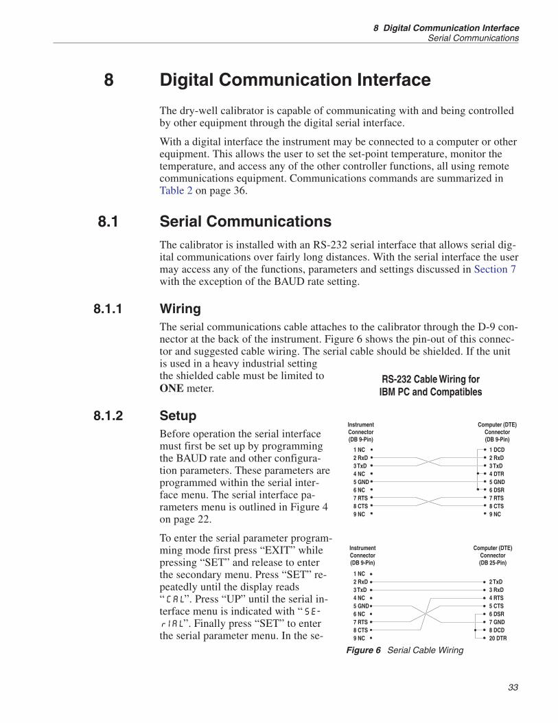
8.1.1 WiringThe serial communications cable attaches to the calibrator through the D-9 con-nector at the back of the instrument. Figure 6 shows the pin-out of this connec-tor and suggested cable wiring. The serial cable should be shielded. If the unitis used in a heavy industrial settingthe shielded cable must be limited toONE meter.
8.1.2 SetupBefore operation the serial interfacemust first be set up by programmingthe BAUD rate and other configura-tion parameters. These parameters areprogrammed within the serial inter-face menu. The serial interface pa-rameters menu is outlined in Figure 4on page 22.
To enter the serial parameter program-ming mode first press “EXIT” whilepressing “SET” and release to enterthe secondary menu. Press “SET” re-peatedly until the display reads“CAL”. Press “UP” until the serial in-terface menu is indicated with “SE-rIAL”. Finally press “SET” to enterthe serial parameter menu. In the se-
33
8 Digital Communication InterfaceSerial Communications
Figure 6 Serial Cable Wiring

rial interface parameters menu are the BAUD rate, the sample rate, the duplexmode, and the linefeed parameter.
8.1.2.1 Baud Rate
The baud rate is the first parameter in the menu. The display will prompt withthe baud rate parameter by showing “BAUd”. Press “SET” to choose to set thebaud rate. The current baud rate value will then be displayed. The baud rate ofthe 9140 serial communications may be programmed to 300, 600, 1200, 2400,4800, or 9600 baud. The baud rate is pre-programmed to 1200 baud. Use “UP”or “DOWN” to change the baud rate value. Press “SET” to set the baud rate tothe new value or “EXIT” to abort the operation and skip to the next parameterin the menu.
8.1.2.2 Sample Period
The sample period is the next parameter in the menu and prompted with“SPEr”. The sample period is the time period in seconds between temperaturemeasurements transmitted from the serial interface. If the sample rate is set to 5for instance then the instrument will transmit the current measurement over theserial interface approximately every five seconds. The automatic sampling isdisabled with a sample period of 0. Press “SET” to choose to set the sample pe-riod. Adjust the period with “UP” or “DOWN” and then use “SET” to set thesample rate to the displayed value.
8.1.2.3 Duplex Mode
The next parameter is the duplex mode indicated with “dUPL”. The duplexmode may be set to half duplex (“HALF”) or full duplex (“FULL”). With fullduplex any commands received by the thermometer via the serial interface areimmediately echoed or transmitted back to the device of origin. With half du-plex the commands are executed but not echoed. The default setting is full du-plex. The mode may be changed using “UP” or “DOWN” and pressing “SET”.
8.1.2.4 Linefeed
The final parameter in the serial interface menu is the linefeed mode. This pa-rameter enables (“On”) or disables (“OFF”) transmission of a linefeed charac-ter (LF, ASCII 10) after transmission of any carriage-return. The default settingis with linefeed on. The mode may be changed using “UP” or “DOWN” andpressing “SET”.
8.1.3 Serial OperationOnce the cable has been attached and the interface set up properly the control-ler immediately begins transmitting temperature readings at the programmedrate. The serial communications uses 8 data bits, one stop bit, and no parity.The set-point and other commands may be sent via the serial interface to set thetemperature set-point and view or program the various parameters. The inter-
9140 Dry-well CalibratorUser’s Guide
34

face commands are discussed in Section. All commands are ASCII characterstrings terminated with a carriage-return character (CR, ASCII 13).
8.2 Interface CommandsThe various commands for accessing the calibrator functions via the digital in-terfaces are listed in this section (see Table 2). These commands are used withthe RS-232 serial interface. The commands are terminated with a carriage-re-turn character. The interface makes no distinction between upper and lowercase letters, hence either may be used. Commands may be abbreviated to theminimum number of letters which determines a unique command. A commandmay be used to either set a parameter or display a parameter depending onwhether or not a value is sent with the command following a “=” character. Forexample “s”<CR> returns the current set-point and “s=150.0”<CR> sets theset-point to 150.0 degrees.
In the following list of commands, characters or data within brackets, “[” and“]”, are optional for the command. A slash, “/”, denotes alternate characters ordata. Numeric data, denoted by “n”, may be entered in decimal or exponentialnotation. Characters are shown in lower case although upper case may be used.Spaces may be added within command strings and will simply be ignored.Backspace (BS, ASCII 8) may be used to erase the previous character. A termi-nating CR is implied with all commands.
35
8 Digital Communication InterfaceInterface Commands

9140 Dry-well CalibratorUser’s Guide
36
Command DescriptionCommandFormat
CommandExample Returned
ReturnedExample
AcceptableValues
Display Temperature
Read current set-point s[etpoint] s set: 9999.99 {C or F} set: 150.00 C
Set current set-point to n s[etpoint]=n s=350 InstrumentRange
Read temperature t[emperature] t t: 9999.9 {C or F} t: 55.6 C
Read temperature units u[nits] u u: x u: C
Set temperature units: u[nits]=c/f C or F
Set temperature units to Celsius u[nits]=c u=c
Set temperature units toFahrenheit
u[nits]=f u=f
Read scan mode sc[an] sc sc: {ON or OFF} sc: ON
Set scan mode sc[an]=on/off sc=on ON or OFF
Read scan rate sr[ate] sr srat: 99.9 C/min srat:12.4 C/min
Set scan rate sr[ate]=n sr=1.1 .1 to 99.9
Read hold ho[ld] ho ho: open/closed, 99.9 {Cor F}
ho: open,30.5 C
Secondary Menu
Read proportional band setting pr[op-band] pr pb: 999.9 pb: 15.9
Set proportional band to n pr[op-band]=n pr=8.83 Depends onConfiguration
Read heater power(duty cycle)
po[wer] po po: 999.9 po: 6.5
Configuration Menu
Calibration Menu
Read R0 calibration parameter r[0] r r0: 999.999 r0: 100.7
Set R0 calibration parameter to n r[0]=n r=100.7 97.0 to 105
Read ALPHA calibrationparameter
a[lpha] al al: 9.999999 al: 0.003865
Set ALPHA calibration parameterto n
a[lpha]=n al=0.003865 .002 to .006
Read DELTA calibrationparameter
d[elta] de de: 1.50
Read DELTA calibrationparameter
d[elta]=n de=1.37 de: 9.9999 0–3.0000
Operating Parameters Menu
Serial Interface Menu
Read serial sample setting sa[mple] sa sa: 9 sa: 1
Set serial sampling setting to nseconds
sa[mple]=n sa=0 0 to 999
Set serial duplex mode: du[plex]=f[ull]/h[alf] FULL or HALF
Set serial duplex mode to full du[plex]=f[ull] du=f
Set serial duplex mode to half du[plex]=h[alf] du=h
Table 2 9140 controller communications commands

37
8 Digital Communication InterfaceInterface Commands
Command DescriptionCommandFormat
CommandExample Returned
ReturnedExample
AcceptableValues
Set serial linefeed mode: lf[eed]=on/of[f] ON or OFF
Set serial linefeed mode to on lf[eed]=on lf=on
Set serial linefeed mode to off lf[eed]=of[f] lf=of
Miscellaneous Other Commands
Read firmware version number *ver[sion] *ver ver.9999,9.99 ver.9140,1.21
Read structure of all commands h[elp] h list of commands
Read ALL operating parameters all all list of parameters
Legend: [] Optional Command data
{} Returns either information
n Numeric data supplied by user
9 Numeric data returned to user
x Character data returned to user
Note: When DUPLEX is set to FULL and a command is sent to READ, the command is returned followed by acarriage return and linefeed. Then the value is returned as indicated in the RETURNED column.
Table 3 9140 controller communications commands continued


9 Test Probe Calibration
For optimum accuracy and stability, allow the calibrator to warm up for 10minutes after power-up and then allow adequate stabilization time after reach-ing the set-point temperature. After completing operation of the calibrator, al-low the well to cool by setting the temperature to 100°C for one-half hourbefore switching the power off.
9.1 Comparison MethodsFor information on automating your testing, contact Hart Scientific.
9.1.1 Calibrating a Single ProbeInsert the probe to be calibrated into the well of the dry-well calibrator. Theprobe should fit snugly into the calibrator probe sleeve yet should not be sotight that it cannot be easily removed. Avoid any dirt or grit that may cause theprobe to jam into the sleeve. Best results are obtained with the probe inserted tothe full depth of the well. Once the probe is inserted into the well, allow ade-quate stabilization time to allow the test probe temperature to settle as de-scribed above. Once the probe has settled to the temperature of the well, it maybe compared to the calibrator display temperature. The display temperatureshould be stable to within 0.1°C degree for best results.
CAUTION: Never introduce any foreign material into the probe hole ofthe insert. Fluids etc. can leak into the calibrator causing damage to thecalibrator or binding and damage to your probe.
9.1.2 Comparison CalibrationComparison calibration involves testing a probe against a similar referenceprobe. The advantage to this method is that better accuracy can be achievedsince errors due to dry-well inaccuracy, stem effect, and drift can be reduced.
After inserting the probes to be calibrated, allow sufficient time for the probesto settle and the temperature of the dry-well to stabilize.
Both the reference probe and the probe under test should be the same size andconstruction. Using probes with different lengths, diameters and materials willhave different stem effects causing an unknown temperature difference. Alldry-wells have horizontal and vertical gradients that change with temperature .This is an unknown variable which can be factored out if probes are the sametype, length, diameter, and material. Probes should be inserted to the samedepth in the well.
The following procedure can be used to calibrate a probe against a referencewhile eliminating error due to temperature gradients between wells.
1. Place the reference probe in one well.
39
9 Test Probe CalibrationComparison Methods

2. Place the probe to be calibrated, the unit under test (UUT), in anotherwell.
3. With the reference inserted into one well and the probe under test in-serted into a second well, make measurements of each.
4. Swap the locations of the reference probe and probe under test. Allowplenty of time for thermal settling.
5. Make another set of measurements of the reference probe and the probeunder test.
6. Average the two measurements of the reference probe. Average the twomeasurements of the probe under test. Averaging the two measurementsin this way eliminates error due to temperature gradients between thetwo wells.
7. You may now compare the averaged measurement of the probe undertest with the averaged measurement of the reference probe.
For best results repeat the test several times at the same temperature and at dif-ferent temperatures.
This method can be used with different types of probes but the user must deter-mine the uncertainty of the measurement.
9.1.3 Calibration of Multiple ProbesFully loading the calibrator with probes increases the time required for the tem-perature to stabilize after inserting the probes. Be sure that the temperature hasstabilized before starting the calibration.
Multiple probes may be calibrated simultaneously using either the direct orcomparison calibration method. Stem effect will cause less error in the compar-ison calibration method than with the direct calibration method.
9.2 Dry-well Characteristics
9.2.1 Vertical GradientThere is a temperature gradient vertically in the test well. The heater has beenapplied to the block in such a way as to compensate for nominal heat losses outof the top of the dry-well and minimize vertical temperature gradients. How-ever, actual heat losses will vary depending on the number and types of probesinserted into the calibrator and the block temperature. For best results, insertprobes the full depth of well.
9.2.2 Heating and Cooling RatesFigures 7 and 8 show typical heating cooling rates of the 9140 dry-wellcalibrator.
9140 Dry-well CalibratorUser’s Guide
40

WARNING: DO NOT remove inserts when heating or when the unit ishot.
9.2.3 Stabilization and AccuracyThe stabilization time of the dry-well calibrator will depend on the conditionsand temperatures involved. Typically the test well will be stable to 0.1°C within5 minutes of reaching the set-point temperature as indicated by the display. Ul-
41
9 Test Probe CalibrationDry-well Characteristics
350
300
250
200
150
100
Blo
ckTe
mp
erat
ure
°C
2 4 6 8 10 12
Ambient
Time in Minutes
Figure 7 Typical Heating Rate
350
300
250
200
150
100
Blo
ckTe
mp
erat
ure
°C
2 4 6 8 10 12
Ambient
Time in Minutes
Figure 8 Typical Cooling Rate

timate stability will be achieved 10 to 20 minutes after reaching the settemperature.
Inserting a cold probe into a well will require another period of stabilizing de-pending on the magnitude of the disturbance and the required accuracy. For ex-ample, inserting a .25 inch diameter room temperature probe into a sleeve at300°C will take 5 minutes to be within 0.1°C of its settled point and will take10 minutes to achieve maximum stability.
Speeding up the calibration process can be accomplished by knowing how soonto make the measurement. It is recommended that typical measurements bemade at the desired temperatures with the desired test probes to establish thesetimes.
9140 Dry-well CalibratorUser’s Guide
42

10 Calibration Procedure
Sometimes the user may want to calibrate the dry-well to improve the tempera-ture set-point accuracy. Calibration is done by adjusting the controller probecalibration constants R0 , ALPHA, and DELTA so that the temperature of thedry-well as measured with a standard thermometer agrees more closely with theset-point. The thermometer used must be able to measure the well temperaturewith higher accuracy than the desired accuracy of the dry-well. By using agood thermometer and following this procedure the dry-well can be calibratedto an accuracy of better than 0.5°C over its full range.
10.1 Calibration PointsIn calibrating the dry-well, R0, ALPHA, and DELTA are adjusted to minimizethe set-point error at each of three different dry-well temperatures. Any threereasonably separated temperatures may be used for the calibration. Improvedresults can be obtained for shorter ranges when using temperatures that are justwithin the most useful operating range of the dry-well. The farther apart thecalibration temperatures, the larger will be the calibrated temperature range butthe calibration error will also be greater over the range. If for instance 150°C to350°C is chosen as the calibration range then the calibrator may achieve an ac-curacy of say ±0.3°C over the range 150 to 350°C. Choosing a range of 200°Cto 300°C may allow the calibrator to have a better accuracy of maybe ±0.2°Cover the range 175 to 325°C but outside that range the accuracy may be only±0.5°C.
10.2 Calibration Procedure1. Choose three set points to use in the calibration of the R0, ALPHA, andDELTA parameters. These set points are generally 50.0°C, 200°C, and 350.0°Cbut other set points may be used if desired or necessary.
2. Set the dry-well to the low set-point. When the dry-well reaches theset-point and the display is stable, wait 15 minutes or so and then take a readingfrom the thermometer. Sample the set-point resistance by holding down theSET key and pressing the DOWN key. Write these values down as T1 and R1respectively.
3. Repeat step 2 for the other two set points recording them as T2 and R2 and T3and R3 respectively.
4. Using the recorded data, calculate new values for the R0, ALPHA, andDELTA parameters using the equations given below:
10.2.1 Compute DELTA:A T T= −3 2
B T T= −2 1
43
10 Calibration ProcedureCalibration Points

CT T T T= ⎡
⎣⎢⎤⎦⎥
−⎡⎣⎢
⎤⎦⎥
− ⎡⎣⎢
⎤⎦⎥
−⎡⎣⎢
⎤⎦
3 3 2 2
1001
100 1001
100 ⎥
DT T T T= ⎡
⎣⎢⎤⎦⎥
−⎡⎣⎢
⎤⎦⎥
− ⎡⎣⎢
⎤⎦⎥
−⎡⎣⎢
⎤⎦
2 2 1 1
1001
100 1001
100 ⎥
E R R= −3 2
F R R= −2 1
deltaAF BE
DE CF= −
−
T1-3 - Measured temperature using thermometer.
R1-3 - Value of set-point resistance from display of 9140. (Press SET andDOWN at the same time.)
where
T1 and R1 are the measured temperature and resistance at 50.0 °C
T2 and R2 are the measured temperature and resistance at 200.0 °C
T3 and R3 are the measured temperature and resistance at 350.0 °C
10.2.2 Compute R0 & ALPHA:
a T deltaT T
1 11 1
1001
100= + ⎡
⎣⎢⎤⎦⎥
−⎡⎣⎢
⎤⎦⎥
a T deltaT T
3 33 3
1001
100= + ⎡
⎣⎢⎤⎦⎥
−⎡⎣⎢
⎤⎦⎥
rzeroR a R a
a a= −
−3 1 1 3
1 3
alphaR R
R a R a= −
−1 3
3 1 1 3
delta is the new value of DELTA computed above
5. Program the new values for DELTA (delta), R0 (rzero) & ALPHA (alpha)into the dry-well using the following steps.
a. Press the SET and EXIT keys at the same time and then press SET untilR0 is displayed.
9140 Dry-well CalibratorUser’s Guide
44
b. Press SET then use the UP or DOWN keys until the correct numericalsetting is displayed. Press SET to accept the new value.
c. Repeat step b. for ALPHA and DELTA.
10.2.3 Accuracy & Repeatability1. Check the accuracy of the dry-well at various points over the calibrationrange.
2. If dry-well does not pass specification at all set-points, repeat CalibrationProcedure.
45
10 Calibration ProcedureCalibration Procedure


11 Maintenance
• The calibration instrument has been designed with the utmost care. Easeof operation and simplicity of maintenance have been a central theme inthe product development. Therefore, with proper care the instrumentshould require very little maintenance. Avoid operating the instrument inan oily, wet, dirty, or dusty environment.
• If the outside of the instrument becomes soiled, it may be wiped cleanwith a damp cloth and mild detergent. Do not use harsh chemicals on thesurface which may damage the paint.
• It is important to keep the well of the calibrator clean and clear of any for-eign matter. Do not use fluid to clean out the well.
• The dry-well calibrator should be handled with care. Avoid knocking ordropping the calibrator.
• For dry-wells with removable probe sleeves, the sleeves can become cov-ered with dust and carbon material. If the buildup becomes too thick, itcould cause the sleeves to become jammed in the wells. Avoid this buildup by periodically buffing the sleeves clean.
• If a sleeve should be dropped, examine the sleeve for deformities beforeinserting it in the well. If there is any chance of jamming the sleeve in thewell, file or grind off the protuberance.
• Do not drop the probe stems into the well. This type of action can cause ashock to the sensor.
• If a hazardous material is spilt on or inside the equipment, the user is re-sponsible for taking the appropriate decontamination steps as outlined bythe national safety council with respect to the material.
• If the mains supply cord becomes damaged, replace it with a cord withthe appropriate gauge wire for the current of the instrument. If there areany questions, call Hart Scientific Customer Service for more informa-tion.
• Before using any cleaning or decontamination method except those rec-ommended by Hart, users should check with Hart Scientific CustomerService to be sure that the proposed method will not damage the equip-ment.
• If the instrument is used in a manner not in accordance with the equip-ment design, the operation of the dry-well may be impaired or safety haz-ards may arise.
47
11 Maintenance

12 Troubleshooting
If problems arise while operating the 9140, this section provides some sugges-tions that may help you solve the problem. A wiring diagram is also included.
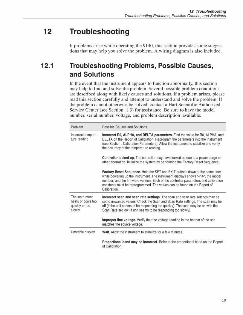
12.1 Troubleshooting Problems, Possible Causes,and SolutionsIn the event that the instrument appears to function abnormally, this sectionmay help to find and solve the problem. Several possible problem conditionsare described along with likely causes and solutions. If a problem arises, pleaseread this section carefully and attempt to understand and solve the problem. Ifthe problem cannot otherwise be solved, contact a Hart Scientific AuthorizedService Center (see Section 1.3) for assistance. Be sure to have the modelnumber, serial number, voltage, and problem description available.
Problem Possible Causes and Solutions
Incorrect tempera-ture reading
Incorrect R0, ALPHA, and DELTA parameters. Find the value for R0, ALPHA, andDELTA on the Report of Calibration. Reprogram the parameters into the instrument(see Section , Calibration Parameters). Allow the instrument to stabilize and verifythe accuracy of the temperature reading.
Controller locked up. The controller may have locked up due to a power surge orother aberration. Initialize the system by performing the Factory Reset Sequence.
Factory Reset Sequence. Hold the SET and EXIT buttons down at the same timewhile powering up the instrument. The instrument displays shows ‘-init-‘, the modelnumber, and the firmware version. Each of the controller parameters and calibrationconstants must be reprogrammed. The values can be found on the Report ofCalibration.
The instrumentheats or cools tooquickly or tooslowly
Incorrect scan and scan rate settings. The scan and scan rate settings may beset to unwanted values. Check the Scan and Scan Rate settings. The scan may beoff (if the unit seems to be responding too quickly). The scan may be on with theScan Rate set low (if unit seems to be responding too slowly).
Improper line voltage. Verify that the voltage reading in the bottom of the unitmatches the source voltage.
Unstable display Wait. Allow the instrument to stabilize for a few minutes.
Proportional band may be incorrect. Refer to the proportional band on the Reportof Calibration.
49
12 TroubleshootingTroubleshooting Problems, Possible Causes, and Solutions

Problem Possible Causes and Solutions
The display showsan error code
Controller problem. The error messages signify the following problems with thecontroller.Err 1 - a RAM errorErr 2 - a NVRAM errorErr 3 - a Structure errorErr 4 - an ADC setup errorErr 5 - an ADC ready errorErr 6 – a defective control sensorErr 7 – a heater errorInitialize the system by performing the Factory Reset Sequence describe above.
Temperature can-not be set above acertain point
Incorrect High Limit parameter. The High Limit parameter may be set below125°C. Check this value as described in Section 7.7, Operating Parameters.
Display is readingincorrectly
The instrument was turned off at high temperatures and reenergized too quickly.Turn the instrument off until the display is completely off and then reenergize.
Display flickerswhen the instru-ment is turned off
This is normal operation and is more prevalent at high temperatures due to SeebeckCoefficient of the thermoelectric cooling devices. Some time is required to fully dis-charge the switching power supply and to complete the power off cycle.
The instrumentdoes not reachtemperature
The specifications for the instrument include an ambient temperature of 23°C. If theambient temperature is above 23°C, the instrument may not be able to reach thelowest specified temperature. Check the ambient temperature if the instrument doesnot reach maximum temperature.
12.2 CE Comments
12.2.1 EMC DirectiveHart Scientific's equipment has been tested to meet the European Electromag-netic Compatibility Directive (EMC Directive, 89/336/EEC). The Declarationof Conformity for your instrument lists the specific standards to which the unitwas tested.
12.2.2 Low Voltage Directive (Safety)In order to,comply with the European Low Voltage Directive (73/23/EEC),Hart Scientific equipment has been designed to meet the IEC 1010-1 (EN61010-1) and IEC 1010-2-010 (EN 61010-2-010) standards.
9140 Dry-well CalibratorUser’s Guide
50