Embed Size (px)
Citation preview

91369 Service Manual
070-1156-00 Rev. A
more time to care

© 2004 Spacelabs Medical, Inc.
All rights reserved. Contents of this publication may not be reproduced in any form without the written permission of Spacelabs Medical. Products of Spacelabs Medical are covered by U.S. and foreign patents and/or pending patents. Printed in U.S.A. Specifications and price change privileges are reserved.
Spacelabs Medical considers itself responsible for the effects on safety, reliability and performance of the equipment only if:
• assembly operations, re-adjustments, modifications or repairs are carried out by persons authorized by Spacelabs Medical, and
• the electrical installation of the relevant room complies with the requirements of the standard in force, and• the equipment is used in accordance with the operations manual.
Spacelabs Medical will make available, on request, such circuit diagrams, component part lists, descriptions, calibration instructions or other information which will assist appropriately qualified technical personnel to repair those parts of the equipment which are classified by Spacelabs Medical as field repairable.
Spacelabs Medical is committed to providing comprehensive customer support beginning with your initial inquiry through purchase, training, and service for the life of your Spacelabs Medical equipment.
CORPORATE OFFICES
U.S.A.
Spacelabs Medical5150 220th Ave SEIssaquah, WA 98029Telephone: 425-657-7200Telephone: 800-522-7025Fax: 425-657-7212
Authorized EC RepresentativeUNITED KINGDOM
Spacelabs Limited71 Great North Road, HatfieldHerts AL9 5ENTelephone: 44-1707-263-570Fax: 44-1707-260-065
BirthNet, Data Shuttle, Flexport, Intesys Clinical Suite, Maternal Obstetrical Monitor, MOM, Mermaid, Multiview, PCIS, PCMS, PrintMaster, Quicknet, Sensorwatch, TRU-CAP, TRU-CUFF, TRU-LINK, UCW, Ultralite, Ultraview, Ultraview Clinical Messenger, Ultraview SL, Uni-Pouch, Universal Flexport, Varitrend and WinDNA are trademarks of Spacelabs Medical, Inc.
Other brands and product names are trademarks of their respective owners.
CAUTION: US Federal law restricts the devices documented herein to sale by, or on the order of, a physician.
RxOnly
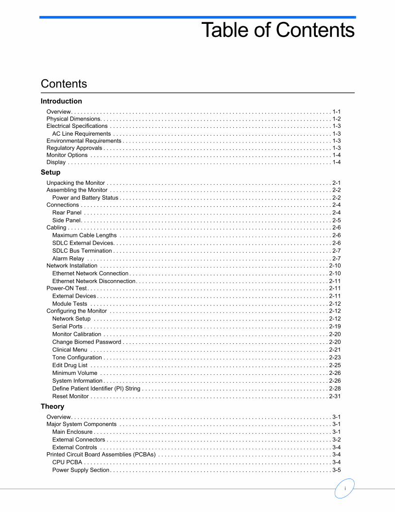
Table of Contents
Contents
IntroductionOverview. . . . . . . . . . . . . . . . . . . . . . . . . . . . . . . . . . . . . . . . . . . . . . . . . . . . . . . . . . . . . . . . . . . . . . . . . . . . . . . . . 1-1Physical Dimensions. . . . . . . . . . . . . . . . . . . . . . . . . . . . . . . . . . . . . . . . . . . . . . . . . . . . . . . . . . . . . . . . . . . . . . . . 1-2Electrical Specifications . . . . . . . . . . . . . . . . . . . . . . . . . . . . . . . . . . . . . . . . . . . . . . . . . . . . . . . . . . . . . . . . . . . . . 1-3
AC Line Requirements . . . . . . . . . . . . . . . . . . . . . . . . . . . . . . . . . . . . . . . . . . . . . . . . . . . . . . . . . . . . . . . . . . . . 1-3Environmental Requirements . . . . . . . . . . . . . . . . . . . . . . . . . . . . . . . . . . . . . . . . . . . . . . . . . . . . . . . . . . . . . . . . . 1-3Regulatory Approvals . . . . . . . . . . . . . . . . . . . . . . . . . . . . . . . . . . . . . . . . . . . . . . . . . . . . . . . . . . . . . . . . . . . . . . . 1-3Monitor Options . . . . . . . . . . . . . . . . . . . . . . . . . . . . . . . . . . . . . . . . . . . . . . . . . . . . . . . . . . . . . . . . . . . . . . . . . . . 1-4Display . . . . . . . . . . . . . . . . . . . . . . . . . . . . . . . . . . . . . . . . . . . . . . . . . . . . . . . . . . . . . . . . . . . . . . . . . . . . . . . . . . 1-4
SetupUnpacking the Monitor . . . . . . . . . . . . . . . . . . . . . . . . . . . . . . . . . . . . . . . . . . . . . . . . . . . . . . . . . . . . . . . . . . . . . . 2-1Assembling the Monitor . . . . . . . . . . . . . . . . . . . . . . . . . . . . . . . . . . . . . . . . . . . . . . . . . . . . . . . . . . . . . . . . . . . . . 2-2
Power and Battery Status . . . . . . . . . . . . . . . . . . . . . . . . . . . . . . . . . . . . . . . . . . . . . . . . . . . . . . . . . . . . . . . . . . 2-2Connections . . . . . . . . . . . . . . . . . . . . . . . . . . . . . . . . . . . . . . . . . . . . . . . . . . . . . . . . . . . . . . . . . . . . . . . . . . . . . . 2-4
Rear Panel . . . . . . . . . . . . . . . . . . . . . . . . . . . . . . . . . . . . . . . . . . . . . . . . . . . . . . . . . . . . . . . . . . . . . . . . . . . . . 2-4Side Panel. . . . . . . . . . . . . . . . . . . . . . . . . . . . . . . . . . . . . . . . . . . . . . . . . . . . . . . . . . . . . . . . . . . . . . . . . . . . . . 2-5
Cabling . . . . . . . . . . . . . . . . . . . . . . . . . . . . . . . . . . . . . . . . . . . . . . . . . . . . . . . . . . . . . . . . . . . . . . . . . . . . . . . . . . 2-6Maximum Cable Lengths . . . . . . . . . . . . . . . . . . . . . . . . . . . . . . . . . . . . . . . . . . . . . . . . . . . . . . . . . . . . . . . . . . 2-6SDLC External Devices. . . . . . . . . . . . . . . . . . . . . . . . . . . . . . . . . . . . . . . . . . . . . . . . . . . . . . . . . . . . . . . . . . . . 2-6SDLC Bus Termination . . . . . . . . . . . . . . . . . . . . . . . . . . . . . . . . . . . . . . . . . . . . . . . . . . . . . . . . . . . . . . . . . . . . 2-7Alarm Relay . . . . . . . . . . . . . . . . . . . . . . . . . . . . . . . . . . . . . . . . . . . . . . . . . . . . . . . . . . . . . . . . . . . . . . . . . . . . 2-7
Network Installation . . . . . . . . . . . . . . . . . . . . . . . . . . . . . . . . . . . . . . . . . . . . . . . . . . . . . . . . . . . . . . . . . . . . . . . 2-10Ethernet Network Connection . . . . . . . . . . . . . . . . . . . . . . . . . . . . . . . . . . . . . . . . . . . . . . . . . . . . . . . . . . . . . . 2-10Ethernet Network Disconnection. . . . . . . . . . . . . . . . . . . . . . . . . . . . . . . . . . . . . . . . . . . . . . . . . . . . . . . . . . . . 2-11
Power-ON Test . . . . . . . . . . . . . . . . . . . . . . . . . . . . . . . . . . . . . . . . . . . . . . . . . . . . . . . . . . . . . . . . . . . . . . . . . . . 2-11External Devices . . . . . . . . . . . . . . . . . . . . . . . . . . . . . . . . . . . . . . . . . . . . . . . . . . . . . . . . . . . . . . . . . . . . . . . . 2-11Module Tests . . . . . . . . . . . . . . . . . . . . . . . . . . . . . . . . . . . . . . . . . . . . . . . . . . . . . . . . . . . . . . . . . . . . . . . . . . 2-12
Configuring the Monitor . . . . . . . . . . . . . . . . . . . . . . . . . . . . . . . . . . . . . . . . . . . . . . . . . . . . . . . . . . . . . . . . . . . . 2-12Network Setup . . . . . . . . . . . . . . . . . . . . . . . . . . . . . . . . . . . . . . . . . . . . . . . . . . . . . . . . . . . . . . . . . . . . . . . . . 2-12Serial Ports . . . . . . . . . . . . . . . . . . . . . . . . . . . . . . . . . . . . . . . . . . . . . . . . . . . . . . . . . . . . . . . . . . . . . . . . . . . . 2-19Monitor Calibration . . . . . . . . . . . . . . . . . . . . . . . . . . . . . . . . . . . . . . . . . . . . . . . . . . . . . . . . . . . . . . . . . . . . . . 2-20Change Biomed Password . . . . . . . . . . . . . . . . . . . . . . . . . . . . . . . . . . . . . . . . . . . . . . . . . . . . . . . . . . . . . . . . 2-20Clinical Menu . . . . . . . . . . . . . . . . . . . . . . . . . . . . . . . . . . . . . . . . . . . . . . . . . . . . . . . . . . . . . . . . . . . . . . . . . . 2-21Tone Configuration . . . . . . . . . . . . . . . . . . . . . . . . . . . . . . . . . . . . . . . . . . . . . . . . . . . . . . . . . . . . . . . . . . . . . . 2-23Edit Drug List . . . . . . . . . . . . . . . . . . . . . . . . . . . . . . . . . . . . . . . . . . . . . . . . . . . . . . . . . . . . . . . . . . . . . . . . . . 2-25Minimum Volume . . . . . . . . . . . . . . . . . . . . . . . . . . . . . . . . . . . . . . . . . . . . . . . . . . . . . . . . . . . . . . . . . . . . . . . 2-26System Information . . . . . . . . . . . . . . . . . . . . . . . . . . . . . . . . . . . . . . . . . . . . . . . . . . . . . . . . . . . . . . . . . . . . . . 2-26Define Patient Identifier (PI) String . . . . . . . . . . . . . . . . . . . . . . . . . . . . . . . . . . . . . . . . . . . . . . . . . . . . . . . . . . 2-28Reset Monitor . . . . . . . . . . . . . . . . . . . . . . . . . . . . . . . . . . . . . . . . . . . . . . . . . . . . . . . . . . . . . . . . . . . . . . . . . . 2-31
TheoryOverview. . . . . . . . . . . . . . . . . . . . . . . . . . . . . . . . . . . . . . . . . . . . . . . . . . . . . . . . . . . . . . . . . . . . . . . . . . . . . . . . . 3-1Major System Components . . . . . . . . . . . . . . . . . . . . . . . . . . . . . . . . . . . . . . . . . . . . . . . . . . . . . . . . . . . . . . . . . . 3-1
Main Enclosure . . . . . . . . . . . . . . . . . . . . . . . . . . . . . . . . . . . . . . . . . . . . . . . . . . . . . . . . . . . . . . . . . . . . . . . . . . 3-1External Connectors . . . . . . . . . . . . . . . . . . . . . . . . . . . . . . . . . . . . . . . . . . . . . . . . . . . . . . . . . . . . . . . . . . . . . . 3-2External Controls . . . . . . . . . . . . . . . . . . . . . . . . . . . . . . . . . . . . . . . . . . . . . . . . . . . . . . . . . . . . . . . . . . . . . . . . 3-4
Printed Circuit Board Assemblies (PCBAs) . . . . . . . . . . . . . . . . . . . . . . . . . . . . . . . . . . . . . . . . . . . . . . . . . . . . . . 3-4CPU PCBA . . . . . . . . . . . . . . . . . . . . . . . . . . . . . . . . . . . . . . . . . . . . . . . . . . . . . . . . . . . . . . . . . . . . . . . . . . . . . 3-4Power Supply Section. . . . . . . . . . . . . . . . . . . . . . . . . . . . . . . . . . . . . . . . . . . . . . . . . . . . . . . . . . . . . . . . . . . . . 3-5
i
91369 Service Manual
Core Processor Subsystem . . . . . . . . . . . . . . . . . . . . . . . . . . . . . . . . . . . . . . . . . . . . . . . . . . . . . . . . . . . . . . . . 3-7PCI Subsystem . . . . . . . . . . . . . . . . . . . . . . . . . . . . . . . . . . . . . . . . . . . . . . . . . . . . . . . . . . . . . . . . . . . . . . . . . 3-11PCI/ISA Bridge . . . . . . . . . . . . . . . . . . . . . . . . . . . . . . . . . . . . . . . . . . . . . . . . . . . . . . . . . . . . . . . . . . . . . . . . . 3-13
Interconnect and Connector PCBAs. . . . . . . . . . . . . . . . . . . . . . . . . . . . . . . . . . . . . . . . . . . . . . . . . . . . . . . . . . . 3-14Bezel Assembly . . . . . . . . . . . . . . . . . . . . . . . . . . . . . . . . . . . . . . . . . . . . . . . . . . . . . . . . . . . . . . . . . . . . . . . . . . 3-15Boot Sequence Overview . . . . . . . . . . . . . . . . . . . . . . . . . . . . . . . . . . . . . . . . . . . . . . . . . . . . . . . . . . . . . . . . . . . 3-17Normal Operation Overview . . . . . . . . . . . . . . . . . . . . . . . . . . . . . . . . . . . . . . . . . . . . . . . . . . . . . . . . . . . . . . . . . 3-17
Main Subsystems and Tasks . . . . . . . . . . . . . . . . . . . . . . . . . . . . . . . . . . . . . . . . . . . . . . . . . . . . . . . . . . . . . . 3-17Display . . . . . . . . . . . . . . . . . . . . . . . . . . . . . . . . . . . . . . . . . . . . . . . . . . . . . . . . . . . . . . . . . . . . . . . . . . . . . . . . . 3-18Parameter Modules . . . . . . . . . . . . . . . . . . . . . . . . . . . . . . . . . . . . . . . . . . . . . . . . . . . . . . . . . . . . . . . . . . . . . . . 3-19CPU PCBA Connectors . . . . . . . . . . . . . . . . . . . . . . . . . . . . . . . . . . . . . . . . . . . . . . . . . . . . . . . . . . . . . . . . . . . . 3-20CPU PCBA Jumpers. . . . . . . . . . . . . . . . . . . . . . . . . . . . . . . . . . . . . . . . . . . . . . . . . . . . . . . . . . . . . . . . . . . . . . . 3-20I/O PCBA Connectors . . . . . . . . . . . . . . . . . . . . . . . . . . . . . . . . . . . . . . . . . . . . . . . . . . . . . . . . . . . . . . . . . . . . . 3-21Interconnect PCBA Connectors . . . . . . . . . . . . . . . . . . . . . . . . . . . . . . . . . . . . . . . . . . . . . . . . . . . . . . . . . . . . . . 3-21
MaintenanceOverview. . . . . . . . . . . . . . . . . . . . . . . . . . . . . . . . . . . . . . . . . . . . . . . . . . . . . . . . . . . . . . . . . . . . . . . . . . . . . . . . . 4-1
Required Test Equipment . . . . . . . . . . . . . . . . . . . . . . . . . . . . . . . . . . . . . . . . . . . . . . . . . . . . . . . . . . . . . . . . . . 4-1Mechanical Inspection . . . . . . . . . . . . . . . . . . . . . . . . . . . . . . . . . . . . . . . . . . . . . . . . . . . . . . . . . . . . . . . . . . . . . . 4-2Electrical Safety Testing . . . . . . . . . . . . . . . . . . . . . . . . . . . . . . . . . . . . . . . . . . . . . . . . . . . . . . . . . . . . . . . . . . . . . 4-2
Definitions . . . . . . . . . . . . . . . . . . . . . . . . . . . . . . . . . . . . . . . . . . . . . . . . . . . . . . . . . . . . . . . . . . . . . . . . . . . . . . 4-2Ground Resistance . . . . . . . . . . . . . . . . . . . . . . . . . . . . . . . . . . . . . . . . . . . . . . . . . . . . . . . . . . . . . . . . . . . . . . . 4-3Chassis Leakage Current Tests . . . . . . . . . . . . . . . . . . . . . . . . . . . . . . . . . . . . . . . . . . . . . . . . . . . . . . . . . . . . . 4-3Patient Lead Leakage Current Tests (Patient Modules) . . . . . . . . . . . . . . . . . . . . . . . . . . . . . . . . . . . . . . . . . . . 4-4
Preventive Maintenance . . . . . . . . . . . . . . . . . . . . . . . . . . . . . . . . . . . . . . . . . . . . . . . . . . . . . . . . . . . . . . . . . . . . . 4-4Error Log . . . . . . . . . . . . . . . . . . . . . . . . . . . . . . . . . . . . . . . . . . . . . . . . . . . . . . . . . . . . . . . . . . . . . . . . . . . . . . . 4-4Touchscreen Calibration . . . . . . . . . . . . . . . . . . . . . . . . . . . . . . . . . . . . . . . . . . . . . . . . . . . . . . . . . . . . . . . . . . . 4-5
Functional Tests . . . . . . . . . . . . . . . . . . . . . . . . . . . . . . . . . . . . . . . . . . . . . . . . . . . . . . . . . . . . . . . . . . . . . . . . . . . 4-5Monitor Self-Test. . . . . . . . . . . . . . . . . . . . . . . . . . . . . . . . . . . . . . . . . . . . . . . . . . . . . . . . . . . . . . . . . . . . . . . . . 4-5Monitor Functional Tests. . . . . . . . . . . . . . . . . . . . . . . . . . . . . . . . . . . . . . . . . . . . . . . . . . . . . . . . . . . . . . . . . . . 4-5
Assembly/Disassembly Procedures . . . . . . . . . . . . . . . . . . . . . . . . . . . . . . . . . . . . . . . . . . . . . . . . . . . . . . . . . . . . 4-7Required Tools and Parts . . . . . . . . . . . . . . . . . . . . . . . . . . . . . . . . . . . . . . . . . . . . . . . . . . . . . . . . . . . . . . . . . . 4-7Setup for Disassembly . . . . . . . . . . . . . . . . . . . . . . . . . . . . . . . . . . . . . . . . . . . . . . . . . . . . . . . . . . . . . . . . . . . . 4-7Installing or Replacing the Optional Recorder Assembly . . . . . . . . . . . . . . . . . . . . . . . . . . . . . . . . . . . . . . . . . . 4-7Inserting Recorder Paper . . . . . . . . . . . . . . . . . . . . . . . . . . . . . . . . . . . . . . . . . . . . . . . . . . . . . . . . . . . . . . . . . 4-10Removing the Bezel Assembly . . . . . . . . . . . . . . . . . . . . . . . . . . . . . . . . . . . . . . . . . . . . . . . . . . . . . . . . . . . . . 4-10Replacing the Display or Touchscreen Assembly, Backlight Inverter, and Power Monitor Assemblies . . . . . . 4-12Replacing the SDLC PCBA. . . . . . . . . . . . . . . . . . . . . . . . . . . . . . . . . . . . . . . . . . . . . . . . . . . . . . . . . . . . . . . . 4-14Replacing the CPU PCBA. . . . . . . . . . . . . . . . . . . . . . . . . . . . . . . . . . . . . . . . . . . . . . . . . . . . . . . . . . . . . . . . . 4-15Removing the Chassis Assembly . . . . . . . . . . . . . . . . . . . . . . . . . . . . . . . . . . . . . . . . . . . . . . . . . . . . . . . . . . . 4-16Replacing the Fan/Battery Contact Assembly. . . . . . . . . . . . . . . . . . . . . . . . . . . . . . . . . . . . . . . . . . . . . . . . . . 4-17Replacing the Interconnect PCBA and Frame . . . . . . . . . . . . . . . . . . . . . . . . . . . . . . . . . . . . . . . . . . . . . . . . . 4-18Replacing/Aligning the Module Door. . . . . . . . . . . . . . . . . . . . . . . . . . . . . . . . . . . . . . . . . . . . . . . . . . . . . . . . . 4-18Replacing the Embedded Nurse Alert Assembly . . . . . . . . . . . . . . . . . . . . . . . . . . . . . . . . . . . . . . . . . . . . . . . 4-18
Cleaning . . . . . . . . . . . . . . . . . . . . . . . . . . . . . . . . . . . . . . . . . . . . . . . . . . . . . . . . . . . . . . . . . . . . . . . . . . . . . . . . 4-19
TroubleshootingOverview. . . . . . . . . . . . . . . . . . . . . . . . . . . . . . . . . . . . . . . . . . . . . . . . . . . . . . . . . . . . . . . . . . . . . . . . . . . . . . . . . 5-1
Required Tools and Parts . . . . . . . . . . . . . . . . . . . . . . . . . . . . . . . . . . . . . . . . . . . . . . . . . . . . . . . . . . . . . . . . . . 5-2Problem Solving . . . . . . . . . . . . . . . . . . . . . . . . . . . . . . . . . . . . . . . . . . . . . . . . . . . . . . . . . . . . . . . . . . . . . . . . . 5-2
System Startup . . . . . . . . . . . . . . . . . . . . . . . . . . . . . . . . . . . . . . . . . . . . . . . . . . . . . . . . . . . . . . . . . . . . . . . . . . . . 5-2Boot Menu . . . . . . . . . . . . . . . . . . . . . . . . . . . . . . . . . . . . . . . . . . . . . . . . . . . . . . . . . . . . . . . . . . . . . . . . . . . . . . . 5-3
Boot Parameters . . . . . . . . . . . . . . . . . . . . . . . . . . . . . . . . . . . . . . . . . . . . . . . . . . . . . . . . . . . . . . . . . . . . . . . . . 5-5Power-ON Diagnostics . . . . . . . . . . . . . . . . . . . . . . . . . . . . . . . . . . . . . . . . . . . . . . . . . . . . . . . . . . . . . . . . . . . . . . 5-5Extended Diagnostics. . . . . . . . . . . . . . . . . . . . . . . . . . . . . . . . . . . . . . . . . . . . . . . . . . . . . . . . . . . . . . . . . . . . . . . 5-6
ii
91369 Service ManualTab
le o
f Co
nte
nts
Diagnostic Menus . . . . . . . . . . . . . . . . . . . . . . . . . . . . . . . . . . . . . . . . . . . . . . . . . . . . . . . . . . . . . . . . . . . . . . . . . . 5-7Main Diagnostic Menu . . . . . . . . . . . . . . . . . . . . . . . . . . . . . . . . . . . . . . . . . . . . . . . . . . . . . . . . . . . . . . . . . . . . 5-7Individual Diagnostic Menu . . . . . . . . . . . . . . . . . . . . . . . . . . . . . . . . . . . . . . . . . . . . . . . . . . . . . . . . . . . . . . . . . 5-8
Error Log. . . . . . . . . . . . . . . . . . . . . . . . . . . . . . . . . . . . . . . . . . . . . . . . . . . . . . . . . . . . . . . . . . . . . . . . . . . . . . . . 5-10Displaying the Error Log . . . . . . . . . . . . . . . . . . . . . . . . . . . . . . . . . . . . . . . . . . . . . . . . . . . . . . . . . . . . . . . . . . 5-10Clearing the Error Log. . . . . . . . . . . . . . . . . . . . . . . . . . . . . . . . . . . . . . . . . . . . . . . . . . . . . . . . . . . . . . . . . . . . 5-11
Diagnostics Failure Messages and Error Codes . . . . . . . . . . . . . . . . . . . . . . . . . . . . . . . . . . . . . . . . . . . . . . . . . 5-11System Troubleshooting. . . . . . . . . . . . . . . . . . . . . . . . . . . . . . . . . . . . . . . . . . . . . . . . . . . . . . . . . . . . . . . . . . . . 5-13
Required Tools/Test Equipment . . . . . . . . . . . . . . . . . . . . . . . . . . . . . . . . . . . . . . . . . . . . . . . . . . . . . . . . . . . . 5-13Display . . . . . . . . . . . . . . . . . . . . . . . . . . . . . . . . . . . . . . . . . . . . . . . . . . . . . . . . . . . . . . . . . . . . . . . . . . . . . . . 5-13Monitor Fails Power-ON Diagnostics . . . . . . . . . . . . . . . . . . . . . . . . . . . . . . . . . . . . . . . . . . . . . . . . . . . . . . . . 5-14Touchscreen . . . . . . . . . . . . . . . . . . . . . . . . . . . . . . . . . . . . . . . . . . . . . . . . . . . . . . . . . . . . . . . . . . . . . . . . . . . 5-15Module Slot . . . . . . . . . . . . . . . . . . . . . . . . . . . . . . . . . . . . . . . . . . . . . . . . . . . . . . . . . . . . . . . . . . . . . . . . . . . . 5-15SDLC Output. . . . . . . . . . . . . . . . . . . . . . . . . . . . . . . . . . . . . . . . . . . . . . . . . . . . . . . . . . . . . . . . . . . . . . . . . . . 5-15Ethernet . . . . . . . . . . . . . . . . . . . . . . . . . . . . . . . . . . . . . . . . . . . . . . . . . . . . . . . . . . . . . . . . . . . . . . . . . . . . . . 5-15Alarm Relay . . . . . . . . . . . . . . . . . . . . . . . . . . . . . . . . . . . . . . . . . . . . . . . . . . . . . . . . . . . . . . . . . . . . . . . . . . . 5-16External Display . . . . . . . . . . . . . . . . . . . . . . . . . . . . . . . . . . . . . . . . . . . . . . . . . . . . . . . . . . . . . . . . . . . . . . . . 5-16Keyboard, Mouse, or Barcode Scanner . . . . . . . . . . . . . . . . . . . . . . . . . . . . . . . . . . . . . . . . . . . . . . . . . . . . . . 5-16Battery. . . . . . . . . . . . . . . . . . . . . . . . . . . . . . . . . . . . . . . . . . . . . . . . . . . . . . . . . . . . . . . . . . . . . . . . . . . . . . . . 5-16Battery Charger. . . . . . . . . . . . . . . . . . . . . . . . . . . . . . . . . . . . . . . . . . . . . . . . . . . . . . . . . . . . . . . . . . . . . . . . . 5-17Recorder . . . . . . . . . . . . . . . . . . . . . . . . . . . . . . . . . . . . . . . . . . . . . . . . . . . . . . . . . . . . . . . . . . . . . . . . . . . . . . 5-17
PartsOverview. . . . . . . . . . . . . . . . . . . . . . . . . . . . . . . . . . . . . . . . . . . . . . . . . . . . . . . . . . . . . . . . . . . . . . . . . . . . . . . . . 6-1Parts List. . . . . . . . . . . . . . . . . . . . . . . . . . . . . . . . . . . . . . . . . . . . . . . . . . . . . . . . . . . . . . . . . . . . . . . . . . . . . . . . . 6-1
Field-Replaceable Parts . . . . . . . . . . . . . . . . . . . . . . . . . . . . . . . . . . . . . . . . . . . . . . . . . . . . . . . . . . . . . . . . . . . 6-1Cables and Adapters . . . . . . . . . . . . . . . . . . . . . . . . . . . . . . . . . . . . . . . . . . . . . . . . . . . . . . . . . . . . . . . . . . . . . 6-3Field-Replaceable Mounting Hardware Parts . . . . . . . . . . . . . . . . . . . . . . . . . . . . . . . . . . . . . . . . . . . . . . . . . . . 6-3Miscellaneous Parts . . . . . . . . . . . . . . . . . . . . . . . . . . . . . . . . . . . . . . . . . . . . . . . . . . . . . . . . . . . . . . . . . . . . . . 6-3
Assembly Drawings and Schematics . . . . . . . . . . . . . . . . . . . . . . . . . . . . . . . . . . . . . . . . . . . . . . . . . . . . . . . . . . . 6-4
Directory of KeysBIOMED Directory of Keys . . . . . . . . . . . . . . . . . . . . . . . . . . . . . . . . . . . . . . . . . . . . . . . . . . . . . . . . . . . . . . . . . . . 7-1
GlossaryAppendix A - Electromagnetic Compatibility
Electromagnetic Emissions. . . . . . . . . . . . . . . . . . . . . . . . . . . . . . . . . . . . . . . . . . . . . . . . . . . . . . . . . . . . . . . . . . . 9-1Electromagnetic Immunity . . . . . . . . . . . . . . . . . . . . . . . . . . . . . . . . . . . . . . . . . . . . . . . . . . . . . . . . . . . . . . . . . . . 9-1Separation Distances . . . . . . . . . . . . . . . . . . . . . . . . . . . . . . . . . . . . . . . . . . . . . . . . . . . . . . . . . . . . . . . . . . . . . . . 9-3
Symbols
iii

Introduction
Contents
Overview . . . . . . . . . . . . . . . . . . . . . . . . . . . . . . . . . . . . . . . . . . . . . . . . . . . . . . . . . . . 1Physical Dimensions . . . . . . . . . . . . . . . . . . . . . . . . . . . . . . . . . . . . . . . . . . . . . . . . . . 2Electrical Specifications. . . . . . . . . . . . . . . . . . . . . . . . . . . . . . . . . . . . . . . . . . . . . . . . 3Environmental Requirements . . . . . . . . . . . . . . . . . . . . . . . . . . . . . . . . . . . . . . . . . . . 3Regulatory Approvals . . . . . . . . . . . . . . . . . . . . . . . . . . . . . . . . . . . . . . . . . . . . . . . . . 3Monitor Options . . . . . . . . . . . . . . . . . . . . . . . . . . . . . . . . . . . . . . . . . . . . . . . . . . . . . . 4Overview
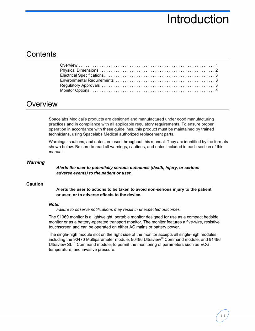
Spacelabs Medical’s products are designed and manufactured under good manufacturing practices and in compliance with all applicable regulatory requirements. To ensure proper operation in accordance with these guidelines, this product must be maintained by trained technicians, using Spacelabs Medical authorized replacement parts.
Warnings, cautions, and notes are used throughout this manual. They are identified by the formats shown below. Be sure to read all warnings, cautions, and notes included in each section of this manual.
WarningAlerts the user to potentially serious outcomes (death, injury, or serious adverse events) to the patient or user.
CautionAlerts the user to actions to be taken to avoid non-serious injury to the patient or user, or to adverse effects to the device.
Note:Failure to observe notifications may result in unexpected outcomes.
The 91369 monitor is a lightweight, portable monitor designed for use as a compact bedside monitor or as a battery-operated transport monitor. The monitor features a five-wire, resistive touchscreen and can be operated on either AC mains or battery power.
The single-high module slot on the right side of the monitor accepts all single-high modules, including the 90470 Multiparameter module, 90496 Ultraview® Command module, and 91496 Ultraview SL™ Command module, to permit the monitoring of parameters such as ECG, temperature, and invasive pressure.
1-1
91369 Service Manual
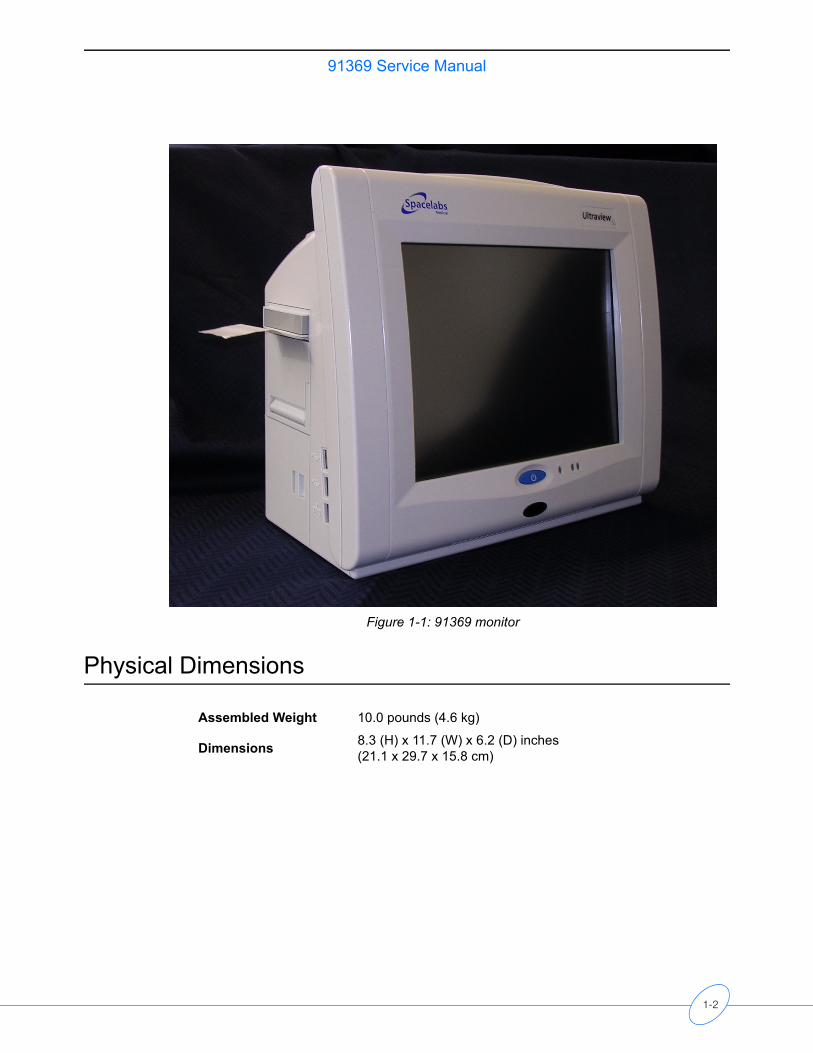
Figure 1-1: 91369 monitor
Physical Dimensions
Assembled Weight 10.0 pounds (4.6 kg)
Dimensions 8.3 (H) x 11.7 (W) x 6.2 (D) inches(21.1 x 29.7 x 15.8 cm)
1-2
91369 Service ManualIn
trod
uctio
n
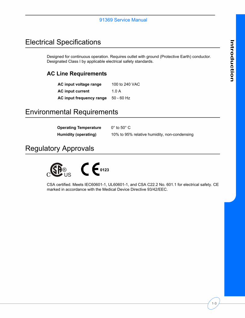
Electrical Specifications
Designed for continuous operation. Requires outlet with ground (Protective Earth) conductor. Designated Class I by applicable electrical safety standards.
AC Line Requirements
Environmental Requirements
Regulatory Approvals
CSA certified. Meets IEC60601-1, UL60601-1, and CSA C22.2 No. 601.1 for electrical safety. CE marked in accordance with the Medical Device Directive 93/42/EEC.
AC input voltage range 100 to 240 VAC
AC input current 1.0 A
AC input frequency range 50 - 60 Hz
Operating Temperature 0° to 50° C
Humidity (operating) 10% to 95% relative humidity, non-condensing
®C US
®C USC
0123
1-3
91369 Service Manual
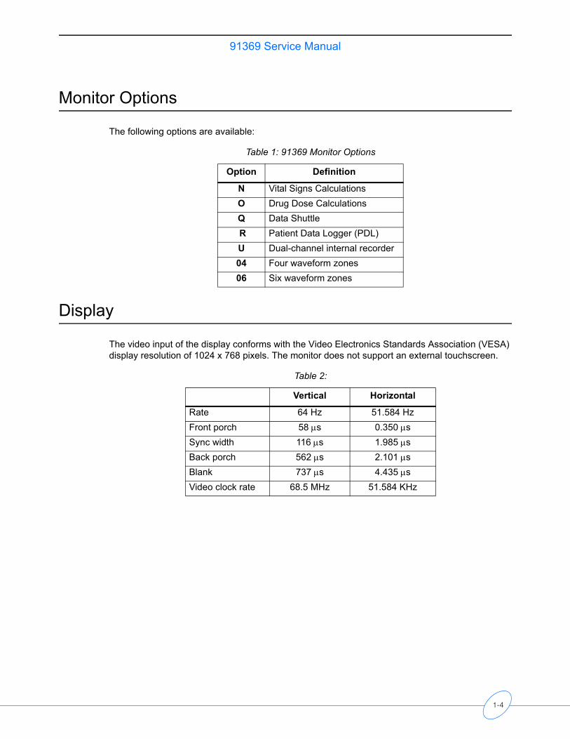
Monitor Options
The following options are available:
Display
The video input of the display conforms with the Video Electronics Standards Association (VESA) display resolution of 1024 x 768 pixels. The monitor does not support an external touchscreen.
Table 1: 91369 Monitor Options
Option Definition
N Vital Signs Calculations O Drug Dose CalculationsQ Data Shuttle R Patient Data Logger (PDL)U Dual-channel internal recorder04 Four waveform zones06 Six waveform zones
Table 2:
Vertical Horizontal
Rate 64 Hz 51.584 HzFront porch 58 µs 0.350 µsSync width 116 µs 1.985 µsBack porch 562 µs 2.101 µsBlank 737 µs 4.435 µsVideo clock rate 68.5 MHz 51.584 KHz
1-4
Setup
Contents
Unpacking the Monitor. . . . . . . . . . . . . . . . . . . . . . . . . . . . . . . . . . . . . . . . . . . . . . . . . 1Assembling the Monitor . . . . . . . . . . . . . . . . . . . . . . . . . . . . . . . . . . . . . . . . . . . . . . . . 2Connections. . . . . . . . . . . . . . . . . . . . . . . . . . . . . . . . . . . . . . . . . . . . . . . . . . . . . . . . . 4Cabling . . . . . . . . . . . . . . . . . . . . . . . . . . . . . . . . . . . . . . . . . . . . . . . . . . . . . . . . . . . . 6Network Installation . . . . . . . . . . . . . . . . . . . . . . . . . . . . . . . . . . . . . . . . . . . . . . . . . . 10Power-ON Test . . . . . . . . . . . . . . . . . . . . . . . . . . . . . . . . . . . . . . . . . . . . . . . . . . . . . 11Configuring the Monitor . . . . . . . . . . . . . . . . . . . . . . . . . . . . . . . . . . . . . . . . . . . . . . . 12Unpacking the Monitor
The 91369 monitor, one or two batteries, external AC power supply, and any optional accessories are all packaged and shipped in a single box. Keep at least one shipping box and its packing materials for re-shipping, if the monitor should ever require factory service.
CautionObserve precautions for handling electrostatic-sensitive devices!
Note:• Never touch electrostatic-sensitive electronic components without following proper
anti-static procedures, including the use of an ESD wrist band and mat. An electrostatic discharge from your fingers can permanently damage electronic components and cause latent failures.
• All static-sensitive electronic components are packaged in static-shielding bags. Retain the bag for repackaging the component should you need to store it or return it to Spacelabs Medical for any reason.
The monitor is typically shipped as follows:
Top Assembly — Contains the main enclosure with installed CPU, power supply, and I/O PCBAs.
Accessories — Contains the external DC power supply, U.S. power cord, international power cords (if applicable), and any cable assemblies ordered.
Before installing the monitor:
Note:When removing items from the shipping containers, ensure that you remove ALL components from each container.
1 Unpack the received equipment.
2 Unpack the mounting hardware.
3 Conduct an equipment audit.
Upon receiving the equipment, complete a detailed inventory to verify that the equipment you received matches your order. This inventory must include serial numbers, model numbers, and all options and cables received. Carefully inspect these items for shipping damage. If any damage is evident, immediately notify the freight company and Spacelabs Medical.
2-1
91369 Service Manual
Assembling the Monitor
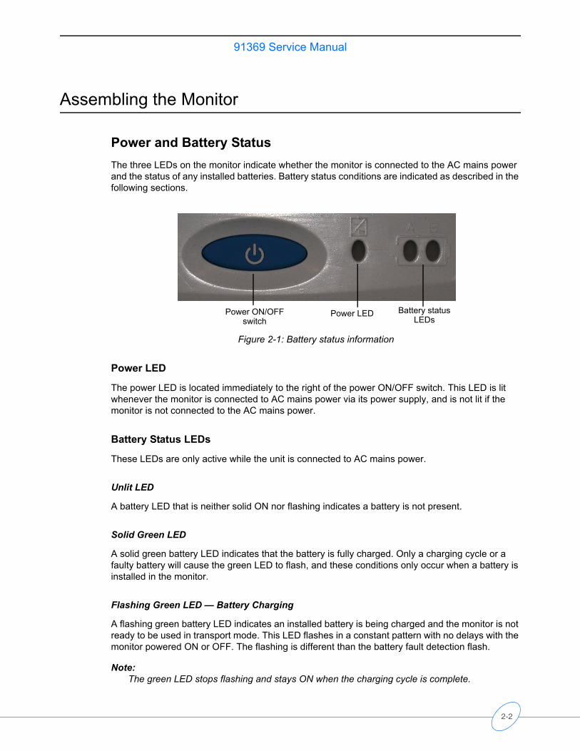
Power and Battery StatusThe three LEDs on the monitor indicate whether the monitor is connected to the AC mains power and the status of any installed batteries. Battery status conditions are indicated as described in the following sections.
Figure 2-1: Battery status information
Power LED
The power LED is located immediately to the right of the power ON/OFF switch. This LED is lit whenever the monitor is connected to AC mains power via its power supply, and is not lit if the monitor is not connected to the AC mains power.
Battery Status LEDs
These LEDs are only active while the unit is connected to AC mains power.
Unlit LED
A battery LED that is neither solid ON nor flashing indicates a battery is not present.
Solid Green LED
A solid green battery LED indicates that the battery is fully charged. Only a charging cycle or a faulty battery will cause the green LED to flash, and these conditions only occur when a battery is installed in the monitor.
Flashing Green LED — Battery Charging
A flashing green battery LED indicates an installed battery is being charged and the monitor is not ready to be used in transport mode. This LED flashes in a constant pattern with no delays with the monitor powered ON or OFF. The flashing is different than the battery fault detection flash.
Note:The green LED stops flashing and stays ON when the charging cycle is complete.
INSERT GRAPHIC HERE
Power LED Battery statusLEDs
Power ON/OFF switch
2-2
91369 Service ManualS
etu
p
Intermittent Flashing Green LED — Battery Fault Detected
An intermittent flashing green LED indicates that this battery will not hold a charge, or is taking too long to charge. The intermittent signal is a repeating pattern of a solid green LED for one second and a flashing LED for one second. An error message is also added to the error log for review by your system administrator.
To determine whether a battery is faulty, power the monitor ON using the front-panel switch and observe the message displayed along the bottom of the monitor screen. Replace a faulty battery with the same battery type.
Installing/Replacing Batteries
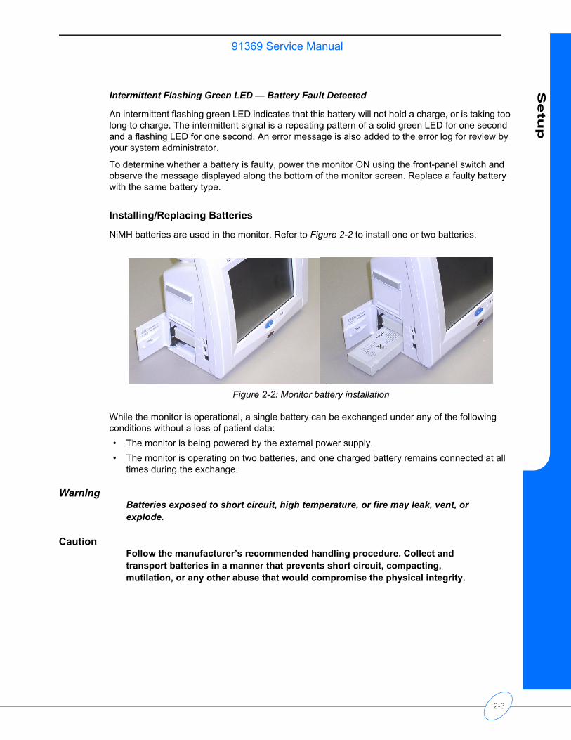
NiMH batteries are used in the monitor. Refer to Figure 2-2 to install one or two batteries.
Figure 2-2: Monitor battery installation
While the monitor is operational, a single battery can be exchanged under any of the following conditions without a loss of patient data:• The monitor is being powered by the external power supply.• The monitor is operating on two batteries, and one charged battery remains connected at all
times during the exchange.
WarningBatteries exposed to short circuit, high temperature, or fire may leak, vent, or explode.
CautionFollow the manufacturer’s recommended handling procedure. Collect and transport batteries in a manner that prevents short circuit, compacting, mutilation, or any other abuse that would compromise the physical integrity.
2-3
91369 Service Manual
Connections
Refer to Figure 2-3 for available connections on the monitor’s rear panel. Refer to Figure 2-4 for available connections on the monitor’s side panel.
Rear Panel
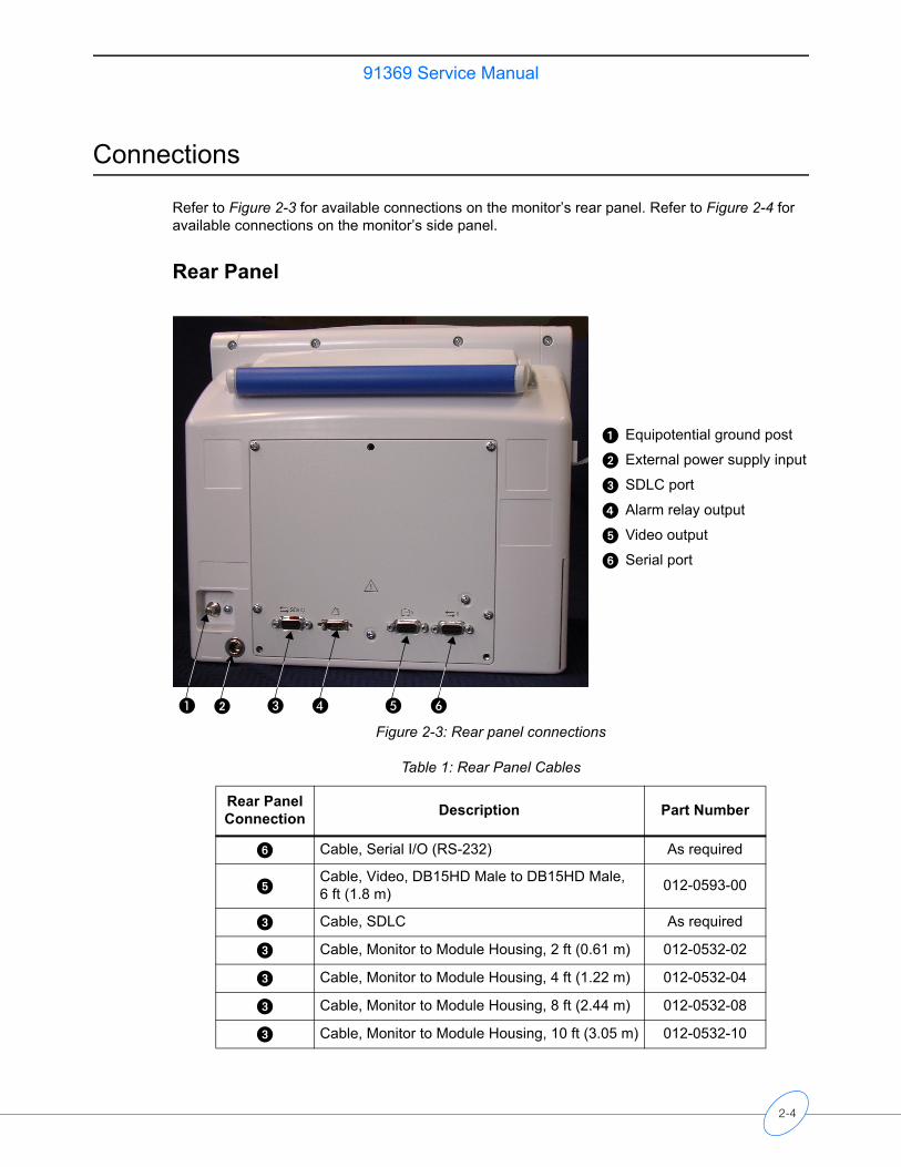
Figure 2-3: Rear panel connections
Table 1: Rear Panel Cables
Rear Panel Connection Description Part Number
� Cable, Serial I/O (RS-232) As required
�Cable, Video, DB15HD Male to DB15HD Male, 6 ft (1.8 m) 012-0593-00
� Cable, SDLC As required
� Cable, Monitor to Module Housing, 2 ft (0.61 m) 012-0532-02
� Cable, Monitor to Module Housing, 4 ft (1.22 m) 012-0532-04
� Cable, Monitor to Module Housing, 8 ft (2.44 m) 012-0532-08
� Cable, Monitor to Module Housing, 10 ft (3.05 m) 012-0532-10
�� � � �
Equipotential ground post
� External power supply input
� SDLC port
� Alarm relay output
� Video output
� Serial port
2-4
91369 Service ManualS
etu
p
CautionFor continued electromagnetic interference (EMI) radiation compliance, use only cables that have been tested and approved by Spacelabs Medical. Refer to Table 2 on page 6-3 for all cable part numbers.
Side Panel
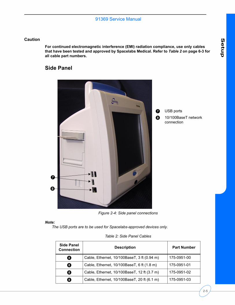
Figure 2-4: Side panel connections
Note:The USB ports are to be used for Spacelabs-approved devices only.
�
� USB ports
� 10/100BaseT networkconnection
Table 2: Side Panel Cables
Side Panel Connection Description Part Number
� Cable, Ethernet, 10/100BaseT, 3 ft (0.94 m) 175-0951-00
� Cable, Ethernet, 10/100BaseT, 6 ft (1.8 m) 175-0951-01
� Cable, Ethernet, 10/100BaseT, 12 ft (3.7 m) 175-0951-02
� Cable, Ethernet, 10/100BaseT, 20 ft (6.1 m) 175-0951-03
2-5
91369 Service Manual
Cabling
Maximum Cable LengthsThe following cables are limited to the indicated maximum length:• SDLC Cable — 40 feet (12.2 m) maximum (total length from the monitor to the last device on
the bus). For longer SDLC cable runs, contact a Spacelabs Medical Field Service Engineer.• Video Cable — 100 feet (30.5 m) maximum (total length from the monitor to the last display).• Ethernet cable (10/100BaseT) — 328 feet (100 m) maximum.
SDLC External DevicesExternal devices (for example, Flexport interfaces) can be connected to the SDLC bus. (In this context, the term “external” means connected to the SDLC bus by cable via an external connector. This is in contrast to modules, which are connected by inserting them into a module housing.)
If no supplementary module housings are present (in addition to the module slot integral to the monitor itself), then external devices are connected directly to the SDLC connector of the monitor.
If one or more supplementary module housings are present, Flexport devices are connected to connector J2 on one of the supplementary module housings.
If multiple module housings are present, external devices must be connected to the last module housing in the daisy-chain; that is, the housing electrically farthest from the monitor on the SDLC bus. Even though multiple connectors may be available, only the SDLC connector on the most distal module housing can be used for connecting external devices. Do not use more than a single Flexport connector, regardless of how many module housings are present.
If multiple Flexport interfaces are to be installed, they must be daisy-chained using the T-cable supplied with those devices. Up to three Flexport interfaces may be connected in this way.
WarningUnreliable system operation will occur if the SDLC bus is not correctly terminated or the maximum cable length is exceeded. Flexport interfaces must be attached to the most distal module housing on the SDLC bus.
SDLC Cable Interconnection
To ensure electromagnetic interference (EMI) compliance, the appropriate Spacelabs Medical 9-pin connector must be used. Refer to the Module Housings and Power Supplies Service Manual (P/N 070-0680-xx).
2-6
91369 Service ManualS
etu
p
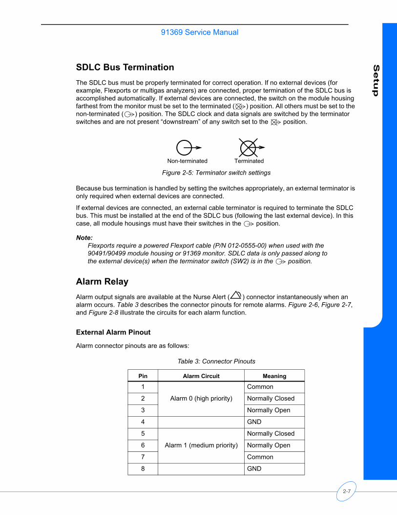
SDLC Bus TerminationThe SDLC bus must be properly terminated for correct operation. If no external devices (for example, Flexports or multigas analyzers) are connected, proper termination of the SDLC bus is accomplished automatically. If external devices are connected, the switch on the module housing farthest from the monitor must be set to the terminated ( ) position. All others must be set to the non-terminated ( ) position. The SDLC clock and data signals are switched by the terminator switches and are not present “downstream” of any switch set to the position.
Figure 2-5: Terminator switch settings
Because bus termination is handled by setting the switches appropriately, an external terminator is only required when external devices are connected.
If external devices are connected, an external cable terminator is required to terminate the SDLC bus. This must be installed at the end of the SDLC bus (following the last external device). In this case, all module housings must have their switches in the position.
Note:Flexports require a powered Flexport cable (P/N 012-0555-00) when used with the 90491/90499 module housing or 91369 monitor. SDLC data is only passed along to the external device(s) when the terminator switch (SW2) is in the position.
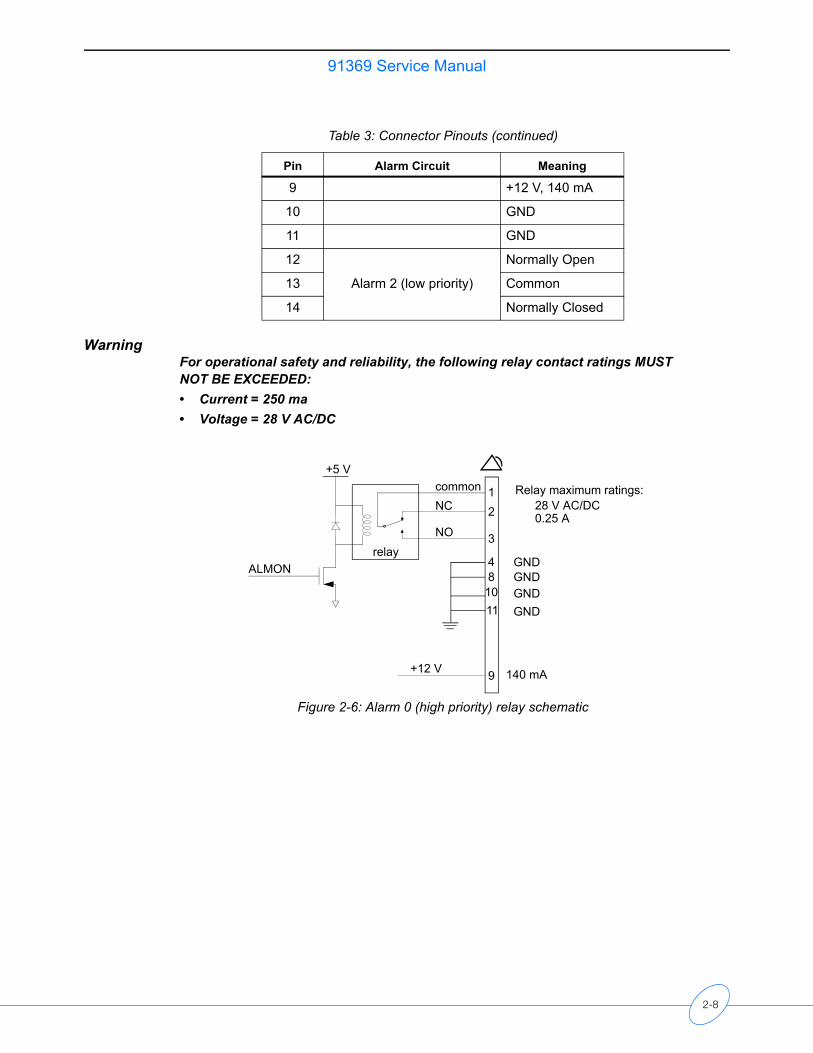
Alarm RelayAlarm output signals are available at the Nurse Alert ( ) connector instantaneously when an alarm occurs. Table 3 describes the connector pinouts for remote alarms. Figure 2-6, Figure 2-7, and Figure 2-8 illustrate the circuits for each alarm function.
External Alarm Pinout
Alarm connector pinouts are as follows:
Non-terminated Terminated
Table 3: Connector Pinouts
Pin Alarm Circuit Meaning
1
Alarm 0 (high priority)
Common
2 Normally Closed
3 Normally Open
4 GND
5
Alarm 1 (medium priority)
Normally Closed
6 Normally Open
7 Common
8 GND
2-7
91369 Service Manual
WarningFor operational safety and reliability, the following relay contact ratings MUST NOT BE EXCEEDED: • Current = 250 ma• Voltage = 28 V AC/DC
Figure 2-6: Alarm 0 (high priority) relay schematic
9 +12 V, 140 mA
10 GND
11 GND
12
Alarm 2 (low priority)
Normally Open
13 Common
14 Normally Closed
Table 3: Connector Pinouts (continued)
Pin Alarm Circuit Meaning
ALMON
+12 V
+5 V
relay
12
3
48
10
9
commonNC
NO
140 mA
Relay maximum ratings:28 V AC/DC0.25 A
11
GNDGNDGNDGND
2-8
91369 Service ManualS
etu
p
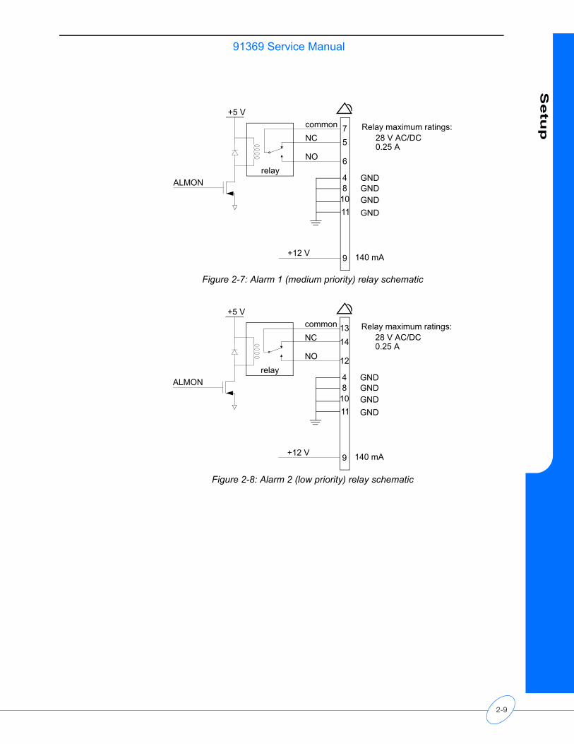
Figure 2-7: Alarm 1 (medium priority) relay schematic
Figure 2-8: Alarm 2 (low priority) relay schematic
ALMON
+12 V
+5 V
relay
75
6
4810
9
commonNC
NO
140 mA
Relay maximum ratings:28 V AC/DC0.25 A
11
GNDGNDGNDGND
ALMON
+12 V
+5 V
relay
1314
12
48
10
9
commonNC
NO
140 mA
Relay maximum ratings:28 V AC/DC0.25 A
11
GNDGNDGNDGND
2-9
91369 Service Manual
Network Installation
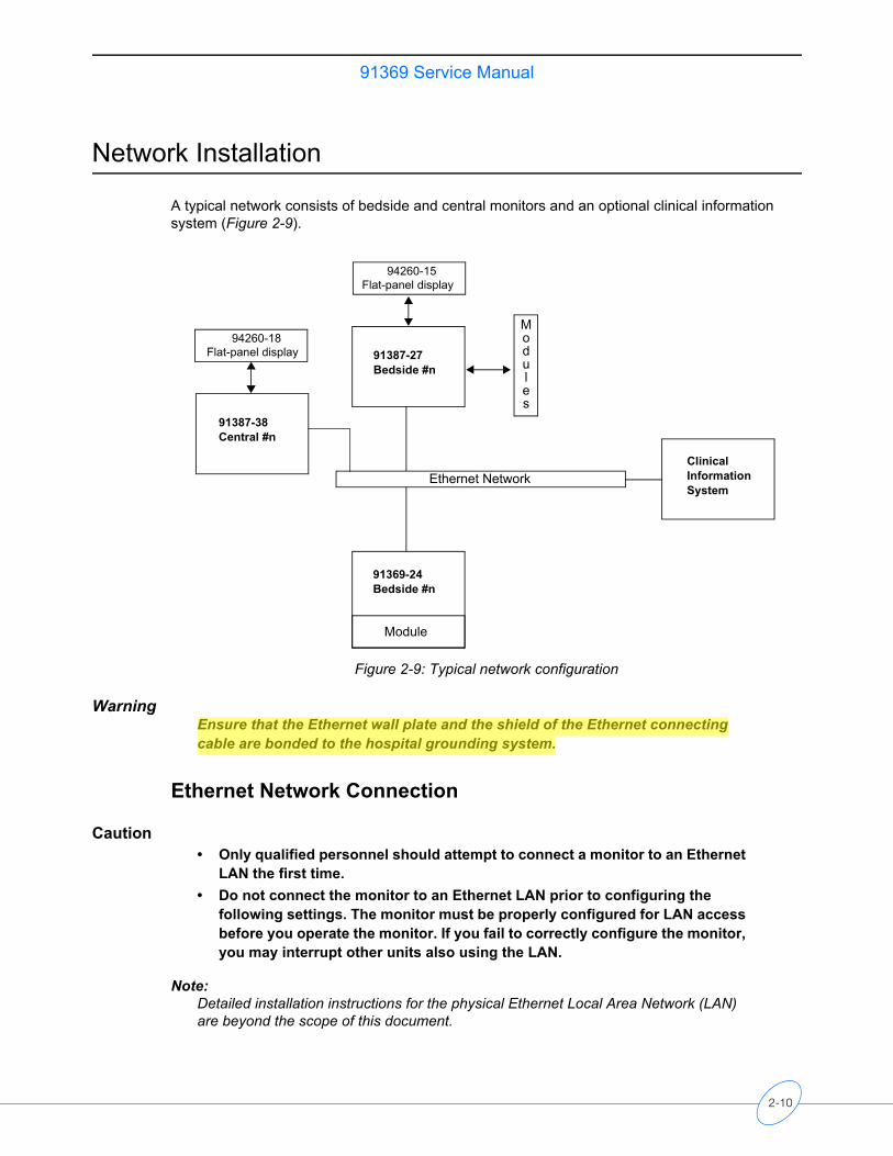
A typical network consists of bedside and central monitors and an optional clinical information system (Figure 2-9).
Figure 2-9: Typical network configuration
WarningEnsure that the Ethernet wall plate and the shield of the Ethernet connecting cable are bonded to the hospital grounding system.
Ethernet Network Connection
Caution• Only qualified personnel should attempt to connect a monitor to an Ethernet
LAN the first time.• Do not connect the monitor to an Ethernet LAN prior to configuring the
following settings. The monitor must be properly configured for LAN access before you operate the monitor. If you fail to correctly configure the monitor, you may interrupt other units also using the LAN.
Note:Detailed installation instructions for the physical Ethernet Local Area Network (LAN) are beyond the scope of this document.
91387-27Bedside #n
91369-24Bedside #n
Module
Clinical Information System
Ethernet Network
91387-38 Central #n
94260-18 Flat-panel display
94260-15 Flat-panel display
Modules
2-10
91369 Service ManualS
etu
p
To connect a monitor onto an existing Spacelabs Medical Ethernet LAN, complete the following steps:
1 Install the monitor on a suitable table or shelf, ensuring that the air flow to the side air intake vents is unobstructed, or use a Spacelabs Medical mounting option.
2 Ensure that the monitor is not connected to the LAN.
3 Plug the power cord attached to the monitor’s DC power supply into a standard hospital-grade AC power supply.
4 Turn ON the monitor.
5 Enter a unique MONITOR ID, BED NAME, and SUBNET for the monitor. Refer to Network Setup on page 2-12 for more information.
6 Attach the 10/100BaseT LAN transceiver cable into the RJ45 connector on the left side of the monitor (� in Figure 2-4 on page 2-5).
7 Connect the other end of the Ethernet cable from the monitor to the nearest port.
8 Configure the monitor’s other network settings as necessary to ensure proper communication on the network. Refer to Network Setup on page 2-12.
Ethernet Network DisconnectionTo remove a monitor from the LAN, disconnect the network cable from the 10/100BaseT network connection (� in Figure 2-4 on page 2-5).
Power-ON Test
Each time the monitor is powered ON: • Diagnostic information displays for approximately 10 seconds. • The embedded alarm light cycles through red, yellow, and cyan.• Monitor keys display on the right side of the screen.
The monitor is now ready for normal operation.
External DevicesIf an external SDLC device, such as a Flexport interface, is to be installed, the 9-pin SDLC connector on the rear of the monitor or the module housing must be used. If multiple SDLC ports on module housings are available, only the SDLC port on the module housing farthest from the monitor can be used for external devices. Set the termination switch to non-terminated ( ) for all module housings and then terminate the external device.
2-11
91369 Service Manual
Module TestsTo verify that the monitor functions correctly with parameter modules:
1 Insert an ECG module without the patient cables connected. Verify that the ECG parameter key is displayed.
2 Connect a patient simulator to the ECG input with a 5-lead patient cable, and set the simulator to a known rate.• Verify that the heart rate and lead being monitored are displayed to the right of the ECG
parameter key. • Verify that the ECG waveform is displayed.
3 Disconnect the patient cable. After 10 seconds, verify that the LEADS OFF message appears, the parameter key flashes yellow, and the medium priority alarm tone sounds.
4 Reconnect the patient cable and verify that the LEADS OFF message clears and the alarm stops.
5 Connect a patient simulator to the invasive pressure inputs.
6 Zero the pressures and verify that the numerics and waveforms are accurate.
7 Verify that the key tone sounds each time a key is selected.
Configuring the Monitor
The Biomed Level menu displays when the biomed password (default is biomed) is entered into the Privileged Access window. Refer to Directory of Keys on page 7-1 for the Biomed Level menu structure.
Network Setup
Note:The NETWORK SETUP key only displays on monitors that are configured for network operation.
Touch NETWORK SETUP to display the Monitor Setup - Network Configuration window. This window contains an on-screen keyboard and three tabs: TCP/IP, Monitor, and Printers. Proper network operation requires that each device on the network have a unique network address, monitor ID, and monitor name.
Editing Tab Fields
The fields within a tab on the Monitor Setup - Network Configuration window can be edited by selecting the field and entering new information using the on-screen or optional external keyboard.
When editing, adding, or deleting, press ENTER or TAB to cycle to the next input cell. Any changed or added items are stored in the monitor’s non-volatile memory when SAVE is selected. The description of each tab indicates when that change takes effect (for example, immediately or after a monitor reset occurs).
2-12
91369 Service ManualS
etu
p
To edit text within a tab:
1 Select an item from the list.-OR-
2 Select an input cell’s text and type any combination of letters, characters, or spaces.
To add an item to a list:
Select the input cell and type the new information.
To delete an item from a list:
1 Select the item.2 Touch Del.3 Enter at least one space (an error message is displayed if no spaces are entered).
TCP/IP Tab
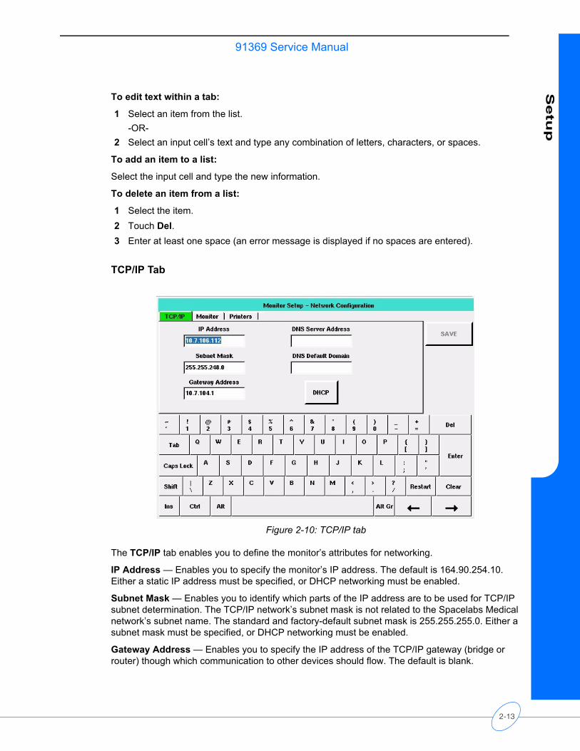
Figure 2-10: TCP/IP tab
The TCP/IP tab enables you to define the monitor’s attributes for networking.
IP Address — Enables you to specify the monitor’s IP address. The default is 164.90.254.10. Either a static IP address must be specified, or DHCP networking must be enabled.
Subnet Mask — Enables you to identify which parts of the IP address are to be used for TCP/IP subnet determination. The TCP/IP network’s subnet mask is not related to the Spacelabs Medical network’s subnet name. The standard and factory-default subnet mask is 255.255.255.0. Either a subnet mask must be specified, or DHCP networking must be enabled.
Gateway Address — Enables you to specify the IP address of the TCP/IP gateway (bridge or router) though which communication to other devices should flow. The default is blank.
2-13
91369 Service Manual
DHCP — (Dynamic Host Configuration Protocol) Used to configure and enable DHCP network configuration. When DHCP is enabled, IP Address, Subnet Mask, and Gateway Address are automatically filled in. To use this service, a DHCP server must be available on the network to respond to DHCP requests.
Note:• A DHCP lease is a TCP/IP configuration given out from the DHCP server that is
valid for a period defined by the DHCP server or forever (no expiration).• Monitors configured for DHCP operation request a lease from the DHCP server
when they boot up or when their existing lease expires during operation. If the DHCP server is not present, the monitor checks the expiration time of the last DHCP lease obtained. If the lease is still valid, the monitor continues to use those values and operates normally. If the lease has expired, the monitor disables TCP/IP networking and displays a NETWORK SIGNAL LOST message to indicate that it is unable to communicate over the network. The monitor continues to request a DHCP lease until it receives one.
• If the monitor’s configured DECNET node ID is a duplicate on the network, the DHCP server can be confused. This may result in a duplicate or invalid DHCP lease and may prevent full network communication.
• The subnet mask must correctly correspond to the network size and type during operation. Monitors may not be able to fully communicate with each other if the DHCP server fails to set the network mask properly.
The DNS server address is in standard TCP/IP address form, while the DNS default domain is a string of ASCII characters. A DHCP server may also provide this information.
Editing this tab is performed as described in Editing Tab Fields on page 2-12. Tabbing order is IP Address >> Subnet Mask >> Gateway Address >> DHCP >> DNS Server Address >> DNS Default Domain >> IP Address. Saved changes made within the tab take effect once the monitor is reset.
2-14
91369 Service ManualS
etu
p
Monitor Tab
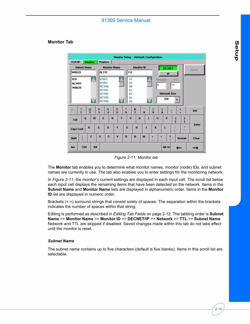
Figure 2-11: Monitor tab
The Monitor tab enables you to determine what monitor names, monitor (node) IDs, and subnet names are currently in use. The tab also enables you to enter settings for the monitoring network.
In Figure 2-11, the monitor’s current settings are displayed in each input cell. The scroll list below each input cell displays the remaining items that have been detected on the network. Items in the Subnet Name and Monitor Name lists are displayed in alphanumeric order. Items in the Monitor ID list are displayed in numeric order.
Brackets (< >) surround strings that consist solely of spaces. The separation within the brackets indicates the number of spaces within that string.
Editing is performed as described in Editing Tab Fields on page 2-12. The tabbing order is Subnet Name >> Monitor Name >> Monitor ID >> DECNET/IP >> Network >> TTL >> Subnet Name. Network and TTL are skipped if disabled. Saved changes made within this tab do not take effect until the monitor is reset.
Subnet Name
The subnet name contains up to five characters (default is five blanks). Items in this scroll list are selectable.
2-15
91369 Service Manual
Monitor Name and Monitor ID
The Monitor Name is the name given to each bedside and central monitor (does not apply to telemetry bed names) to help the users identify monitors on the network. The Monitor Name contains five characters (default is SL001).
The Monitor ID is the numeric ID assigned to a monitor. Each device on the network must have a unique Monitor ID. This can be any number from 1 to 1023, depending on the Network Size selected.
To prevent duplication of currently used monitor names and IDs, items in these lists are not selectable. The error checking procedure performed when SAVE is selected also specifically checks for duplications.
Note:Items in these lists only display when the monitor is connected to the network.
DECNET/IP
You can configure the monitor to operate using either Spacelabs DECNET or TCP/IP network protocols. If you are communicating with 903xx Spacelabs Medical monitors, you must select DECNET.
Network
The IP multicast group number of the monitor provides a filter to logically isolate one monitor from another on TCP/IP installations. Up to 32 network numbers are available (0 to 31) with 0 as the default.
Note:This is disabled if DECNET is selected.
TTL (Time to Live)
The allowed number of hops the IP packet can take across network devices. TTL values are 1 to 64, with 16 as the default.
Note:TTL is disabled if DECNET is selected.
2-16
91369 Service ManualS
etu
p
Network Size
The network size allows configuration as:
64 — Monitor IDs from 1 to 64 are supported. No more than 64 total monitor devices can be on the network. Provides complete network compatibility with legacy Spacelabs monitors.
250 — Monitor IDs from 1 to 250 are supported.
Note:903xx monitors must have the Expanded Network option installed or they will not communicate correctly with devices with Monitor IDs above 64.
640 — Monitor IDs from 1 to 127 and from 512 to 1023 are supported with the following restrictions. All model 903xx Spacelabs Medical monitors must use monitor IDs 1 to 127, inclusive. All model 91xxx monitors must be configured with monitor IDs from 512 to 1023, inclusive.
1000 — Monitor IDs from 1 to 1023 are supported (compatible only with Spacelabs Medical 91xxx series monitors).
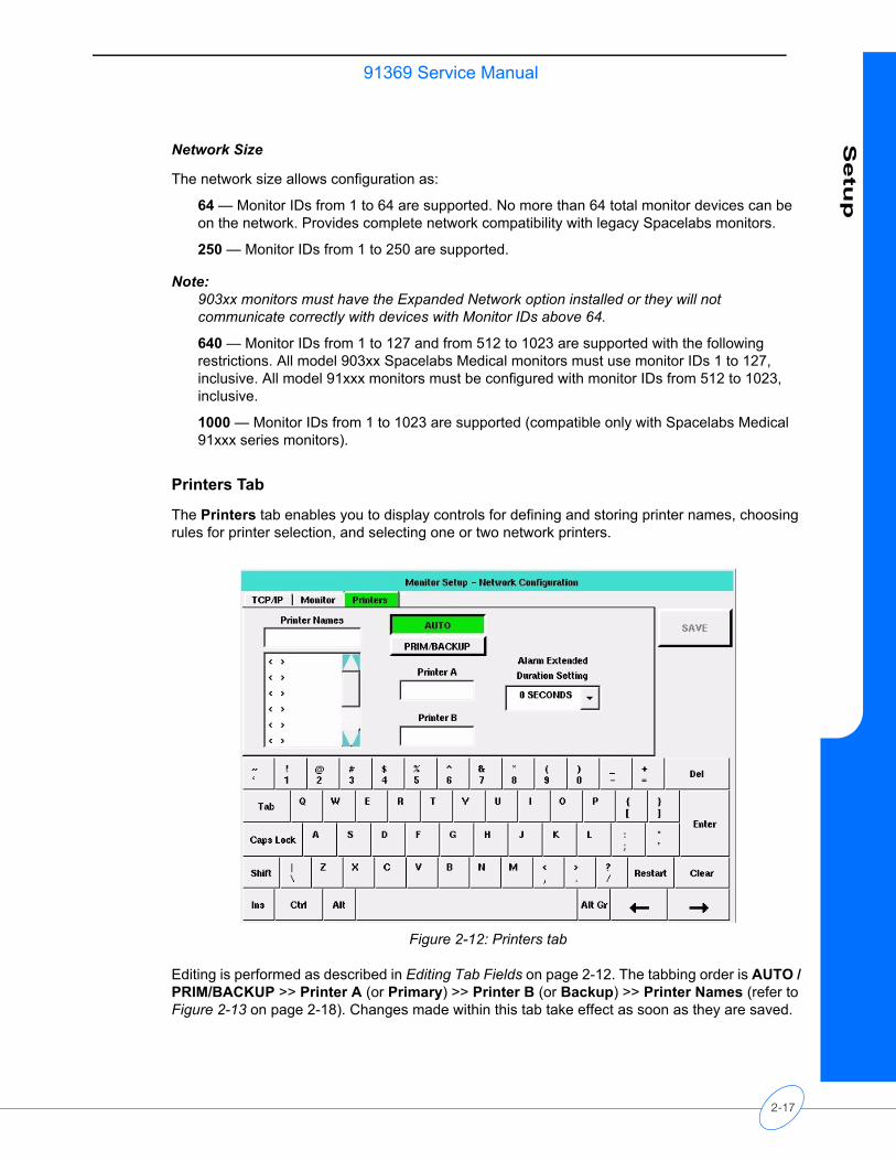
Printers Tab
The Printers tab enables you to display controls for defining and storing printer names, choosing rules for printer selection, and selecting one or two network printers.
Figure 2-12: Printers tab
Editing is performed as described in Editing Tab Fields on page 2-12. The tabbing order is AUTO / PRIM/BACKUP >> Printer A (or Primary) >> Printer B (or Backup) >> Printer Names (refer to Figure 2-13 on page 2-18). Changes made within this tab take effect as soon as they are saved.
2-17
91369 Service Manual
Printer Names
The Printer Names list displays up to eight, selectable printer names previously stored in this monitor, in the order in which they were stored. To display a new or changed name in the list, select that printer name from the list. Printer names contain up to five characters (default is five blanks).
Note:• Printer names are explicitly entered and may be duplicated. To clear a printer
name from the list, select that name, touch Clear, touch Enter, and then touch SAVE.
• A local (SDLC) printer can be either a bedside printer or network printer, depending on the printer name selected in this list. A local printer is configured as a network printer if the local monitor’s name is selected. Otherwise, a local printer functions as the bedside printer.
AUTO / PRIM/BACKUP
The AUTO / PRIM/BACKUP key selects which set of printer selection rules the monitor uses for selecting network printers. It does not affect the monitor’s selection of whether a networked or non-networked printer is used. Any changes made to the printer selection mode using this key take effect immediately, regardless of monitor type. The default setting is AUTO, which selects the destination printer using the weight-based printer selection rules. (Refer to the Ultraview SL Operations Manual, P/N 070-1150-xx, located on CD-ROM P/N 084-1101-xx for additional information).
When PRIM/BACKUP is selected, the monitor automatically selects the primary printer, unless that printer is unable to accept the recording. In that instance, the monitor then selects the backup printer. If the backup printer is also unable to accept the recording, the monitor displays an Unable to record message.
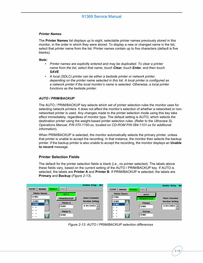
Printer Selection Fields
The default for the printer selection fields is blank (i.e., no printer selected). The labels above these fields vary, based on the current setting of the AUTO / PRIM/BACKUP key. If AUTO is selected, the labels are Printer A and Printer B. If PRIM/BACKUP is selected, the labels are Primary and Backup (Figure 2-13).
Figure 2-13: AUTO / PRIM/BACKUP selection differences
2-18
91369 Service ManualS
etu
p
To define a printer name:
1 Select a printer name from the Printer Names list.
2 Select one of the two printer selection fields. The new value displays in the selected field.
Extended Alarm Recording Duration
Selecting the Extended Alarm Recording Duration list enables you to add 0 Seconds (default), 6 Seconds, or 12 Seconds to each alarm recording.
When 0 Seconds is selected, alarm recordings end as defined by the alarming parameter when the alarm event ends. The other two selections extend any alarm recording by 6 or 12 seconds, enabling the offset of long-duration events to be printed.
Note:• Alarm recordings persist for the duration of the event as defined by the parameter
that initiated the alarm recording. Alarm recordings for long duration events (for example, apnea, asystole, ventricular fibrillation, and ventricular tachycardia) may end before the offset of these long-duration events are printed.
• The extended alarm recording duration applies to ALL alarms from all parameters.
Serial Ports Refer to Directory of Keys on page 7-1 for the menu structure.
Patient Data Logger (Option R)
The Patient Data Logger option automatically sends patient vital signs from the monitor to a serial external device, such as a printer or a terminal. Episodic patient data is also sampled and transmitted. The output is in the form of ASCII text byte strings and is printed using standard RS-232 serial communications via the monitor’s serial port (refer to the Ultraview SL Operations Manual, P/N 070-1150-xx, located on CD-ROM P/N 084-1101-xx for configuration information).
This option continues to send data whether the external device is on-line or off-line. Data transmission can be stopped by reassigning the data port or disabling the Patient Data Logger option.
Communication between the monitor and the external device is set up by assigning the serial port to Patient Data Logger and then adjusting the serial port settings. The various serial settings can be adjusted to suit the device attached to the serial port.
To set up Patient Data Logger:
1 Touch MONITOR SETUP.
2 Touch PRIVILEGED ACCESS.
3 Enter the biomed password (default is biomed).
4 Touch SERIAL PORTS and select 1.
5 Touch ASSIGNMENT.
6 Touch DATA LOGGER.
7 Touch PREVIOUS MENU.
2-19
91369 Service Manual
To set serial settings:
1 Touch SETTINGS.
2 Touch the desired setting key(s) to display and set the desired settings.
3 Touch NORMAL SCREEN to effect changes.
Monitor CalibrationThe MONITOR CALIBRATION key in the Biomed Level menu allows you to perform a touchscreen calibration in the event the touchscreen becomes difficult to use or a replacement has been installed. Refer to Touchscreen Calibration on page 4-5 for instructions on performing this calibration.
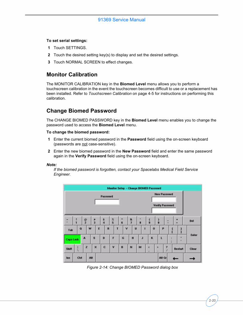
Change Biomed PasswordThe CHANGE BIOMED PASSWORD key in the Biomed Level menu enables you to change the password used to access the Biomed Level menu.
To change the biomed password:
1 Enter the current biomed password in the Password field using the on-screen keyboard (passwords are not case-sensitive).
2 Enter the new biomed password in the New Password field and enter the same password again in the Verify Password field using the on-screen keyboard.
Note:If the biomed password is forgotten, contact your Spacelabs Medical Field Service Engineer.
Figure 2-14: Change BIOMED Password dialog box
2-20
91369 Service ManualS
etu
p
Clinical MenuThe CLINICAL MENU key in the Biomed Level menu provides access to several features described in the sections that follow. Refer to Directory of Keys on page 7-1 for the menu structure.
Time/Date
The TIME/DATE key accesses the Monitor Setup - Time/Date menu. The current time or date displays above the menu. The time displays in either a 12- or 24-hour format. Network monitors display the network time; standalone monitors display the internal system time.• TIME/DATE — Select TIME or DATE, use the arrow keys to set the correct time or date, and
touch ENTER.• 24 HOURS — Displays the time in a 24-hour format. Touch ENTER to complete the selection.• AM/PM — Select AM or PM to display the time in a 12-hour format, and then touch ENTER.
Note:Setting the time on any networked monitor sets the time for all monitors on that network.
Preselected Recordings
Refer to the Printing chapter in the Ultraview SL Operations Manual (P/N 070-1150-xx), located on CD-ROM P/N 084-1101-xx, for information regarding preselected recordings.
Units of Measurement
The UNITS OF MEASURE key provides access to the units of measurement that the monitor uses for input, display, and printing of values for pressure, height, and weight measurements. Each key’s label indicates the available selections. Reset the monitor after making changes in this menu.
User Access
The USER ACCESS key allows the system administrator to preset certain functions and features of the monitor for availability to non-privileged-access users. • PATIENT TYPE / ON/OFF — Enables (ON) or disables (OFF) the “Patient Type” selection in
the Admit/Discharge dialog box.• PARAMETER CONFIG / ON/OFF (bedside monitors only) — Displays (ON) or removes (OFF)
the PARAMETER CONFIG key in the Monitor Config menu.• RECORDING DURATION / ON/OFF — Displays (ON) or removes (OFF) the RECORDING
DURATION key in the Recorder Config menu.• SUBNET ACCESS / ON/OFF — Select ON to display keys for other care areas (subnets)
within bed selection windows for features such as Alarm Watch, Remote View, Screen Format, etc.
• DEFAULT ENG. SAV MODE / ON/OFF — Turns the monitor’s power-on, default-energy-saving, power mode ON or OFF and changes the setting of the ENERGY SAVING MODE / ON/OFF key that appears when the monitor is operating on battery power.
2-21
91369 Service Manual
Alarm Setup
Touch the ALARM SETUP key to display the following keys:• REMOTE ACCESS / ON/OFF — Select ON to allow alarm limits from this monitor’s
parameters to be changed remotely (from central monitors or from bedside monitors via Remote View).
Selecting OFF ensures that alarm limits for this monitor’s parameters can only be changed at this monitor.
• ALARM SUSPEND / ON/OFF — Select ON to enable access to the TONE RESET/ALM SUSPEND key’s Alarm Suspend function.
• TREND SUSPEND / ON/OFF — Select ON to allow trending to occur when all alarms are suspended via the ALARM SUSPEND key.
• ALARM RELAY — Allows characteristics of the monitor’s external alarm relay to be defined. When an alarm occurs, this relay can activate an external device to identify which monitor is in alarm. In general terms, monitors activate their alarm relay whenever an alarm is occurring on that monitor.- RELAY TIMEOUT / 0 SEC/10 SEC — Select 0 SEC to deactivate the alarm relay when the
alarm ends. Select 10 SEC to deactivate the alarm relay 10 seconds after the alarm ends.- ALARM LEVEL — The alarm relay can be activated for all alarms or for alarms at or above
the selected priority only. Selections of HIGH, MEDIUM, and LOW are available. For example, selecting MEDIUM results in activation of the alarm relay for HIGH and MEDIUM priority alarms, but not for LOW priority alarms.
• QRS/SPO2 TONE ENABLE / ALWAYS/DURING ALARM — Controls whether the monitor sounds the QRS or SpO2 tone all the time (ALWAYS) or only during alarm conditions (DURING ALARM). The QRS or SpO2 tone must also be enabled using the controls within those parameters’ menus.
Alarm Watch Setup
The ALARM WATCH SETUP key controls how this monitor responds to alarm watch messages received from other monitors.• ROTATE ALARM WATCH / ON/OFF — This key enables (ON) and disables (OFF) the alarm
watch rotation feature (default is OFF).• ALARM WATCH ROTATION / PRIORITY/SIMPLE — When a monitor receives more than one
alarm watch message at a time, it uses a “first-in, first-out” rotation scheme to display the alarming parameters. This key is only enabled when ROTATE ALARM WATCH is set to ON. The following choices of rotation schemes are available:- SIMPLE rotation cycles through the alarming parameters in the order they go into alarm
(first come, first served). - PRIORITY rotation cycles through the alarming parameters based on each parameter’s
alarm priority (for example, parameters with high-priority alarms display before parameters with medium- or low-priority alarms).
• ROTATION TIME / 15 SEC/30 SEC — You can choose to display an alarm watch for either 15 or 30 seconds before cycling to the next alarm watch if there are two or more alarm-watched beds in alarm. This key is only enabled when ROTATE ALARM WATCH is set to ON.
2-22
91369 Service ManualS
etu
p
Change Clinical Password
The CHANGE CLINICAL PASSWORD key enables you to change the password used to access the Clinical Level menu.
To change the clinical password:
1 Enter the current clinical password in the Password field using the on-screen keyboard (passwords are not case-sensitive).
2 Enter the new clinical password in the New Password field and enter the same password again in the Verify Password field using the on-screen keyboard.
Note:If the clinical password is forgotten, contact your system administrator.
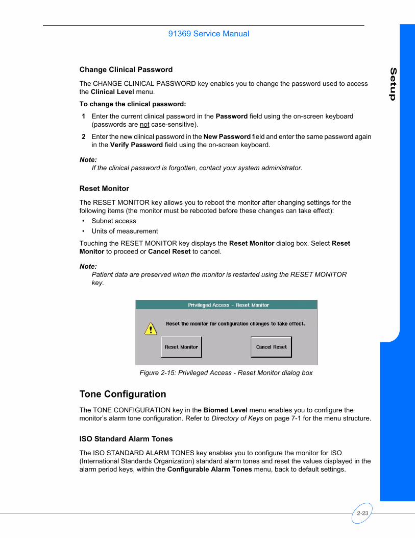
Reset Monitor
The RESET MONITOR key allows you to reboot the monitor after changing settings for the following items (the monitor must be rebooted before these changes can take effect):• Subnet access• Units of measurement
Touching the RESET MONITOR key displays the Reset Monitor dialog box. Select Reset Monitor to proceed or Cancel Reset to cancel.
Note:Patient data are preserved when the monitor is restarted using the RESET MONITOR key.
Figure 2-15: Privileged Access - Reset Monitor dialog box
Tone Configuration The TONE CONFIGURATION key in the Biomed Level menu enables you to configure the monitor’s alarm tone configuration. Refer to Directory of Keys on page 7-1 for the menu structure.
ISO Standard Alarm Tones
The ISO STANDARD ALARM TONES key enables you to configure the monitor for ISO (International Standards Organization) standard alarm tones and reset the values displayed in the alarm period keys, within the Configurable Alarm Tones menu, back to default settings.
2-23
91369 Service Manual
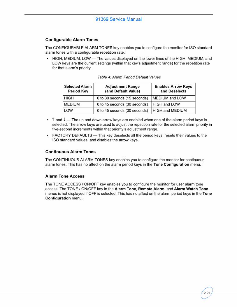
Configurable Alarm Tones
The CONFIGURABLE ALARM TONES key enables you to configure the monitor for ISO standard alarm tones with a configurable repetition rate. • HIGH, MEDIUM, LOW — The values displayed on the lower lines of the HIGH, MEDIUM, and
LOW keys are the current settings (within that key’s adjustment range) for the repetition rate for that alarm’s priority.
• ↑ and ↓ — The up and down arrow keys are enabled when one of the alarm period keys is selected. The arrow keys are used to adjust the repetition rate for the selected alarm priority in five-second increments within that priority’s adjustment range.
• FACTORY DEFAULTS — This key deselects all the period keys, resets their values to the ISO standard values, and disables the arrow keys.
Continuous Alarm Tones
The CONTINUOUS ALARM TONES key enables you to configure the monitor for continuous alarm tones. This has no affect on the alarm period keys in the Tone Configuration menu.
Alarm Tone Access
The TONE ACCESS / ON/OFF key enables you to configure the monitor for user alarm tone access. The TONE / ON/OFF key in the Alarm Tone, Remote Alarm, and Alarm Watch Tone menus is not displayed if OFF is selected. This has no affect on the alarm period keys in the Tone Configuration menu.
Table 4: Alarm Period Default Values
Selected Alarm Period Key
Adjustment Range (and Default Value)
Enables Arrow Keys and Deselects
HIGH 0 to 30 seconds (15 seconds) MEDIUM and LOWMEDIUM 0 to 45 seconds (30 seconds) HIGH and LOWLOW 0 to 45 seconds (30 seconds) HIGH and MEDIUM
2-24
91369 Service ManualS
etu
p
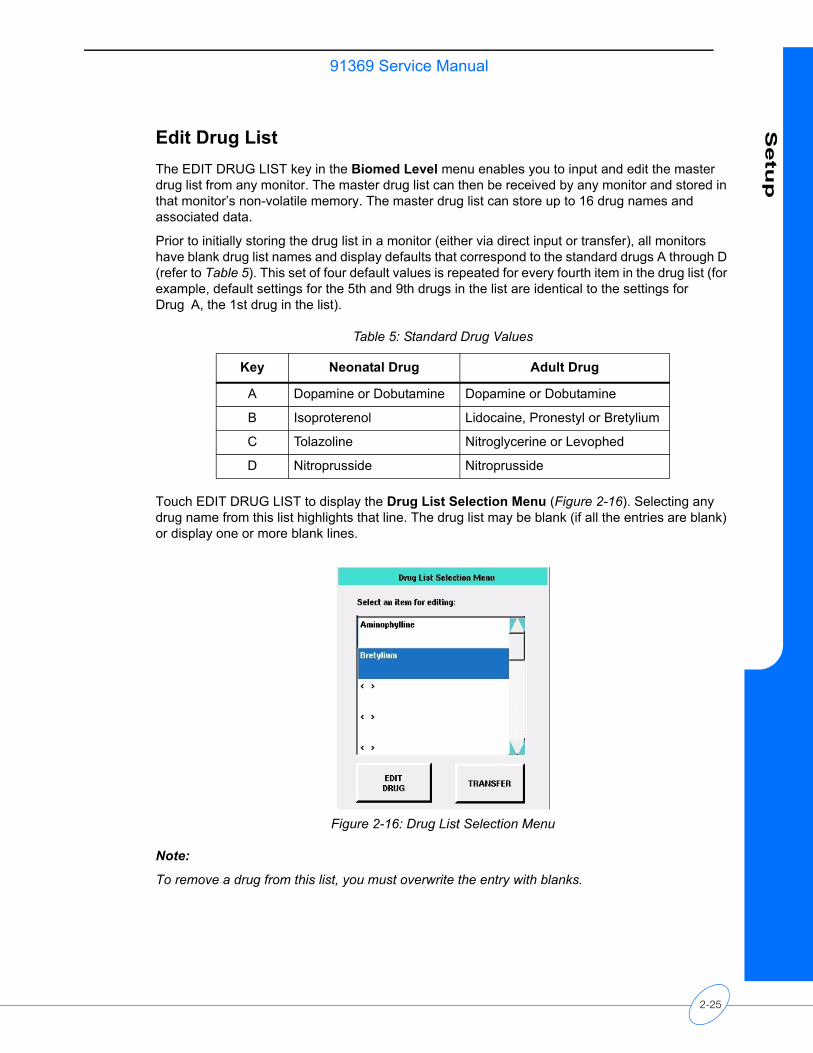
Edit Drug List The EDIT DRUG LIST key in the Biomed Level menu enables you to input and edit the master drug list from any monitor. The master drug list can then be received by any monitor and stored in that monitor’s non-volatile memory. The master drug list can store up to 16 drug names and associated data.
Prior to initially storing the drug list in a monitor (either via direct input or transfer), all monitors have blank drug list names and display defaults that correspond to the standard drugs A through D (refer to Table 5). This set of four default values is repeated for every fourth item in the drug list (for example, default settings for the 5th and 9th drugs in the list are identical to the settings for Drug A, the 1st drug in the list).
Touch EDIT DRUG LIST to display the Drug List Selection Menu (Figure 2-16). Selecting any drug name from this list highlights that line. The drug list may be blank (if all the entries are blank) or display one or more blank lines.
Figure 2-16: Drug List Selection Menu
Note:
To remove a drug from this list, you must overwrite the entry with blanks.
Table 5: Standard Drug Values
Key Neonatal Drug Adult Drug
A Dopamine or Dobutamine Dopamine or Dobutamine
B Isoproterenol Lidocaine, Pronestyl or Bretylium
C Tolazoline Nitroglycerine or Levophed
D Nitroprusside Nitroprusside
2-25
91369 Service Manual
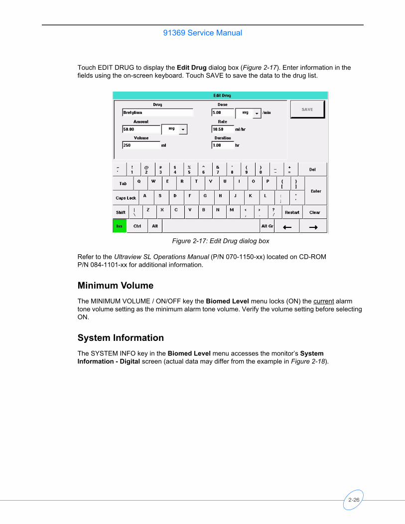
Touch EDIT DRUG to display the Edit Drug dialog box (Figure 2-17). Enter information in the fields using the on-screen keyboard. Touch SAVE to save the data to the drug list.
Figure 2-17: Edit Drug dialog box
Refer to the Ultraview SL Operations Manual (P/N 070-1150-xx) located on CD-ROM P/N 084-1101-xx for additional information.
Minimum VolumeThe MINIMUM VOLUME / ON/OFF key the Biomed Level menu locks (ON) the current alarm tone volume setting as the minimum alarm tone volume. Verify the volume setting before selecting ON.
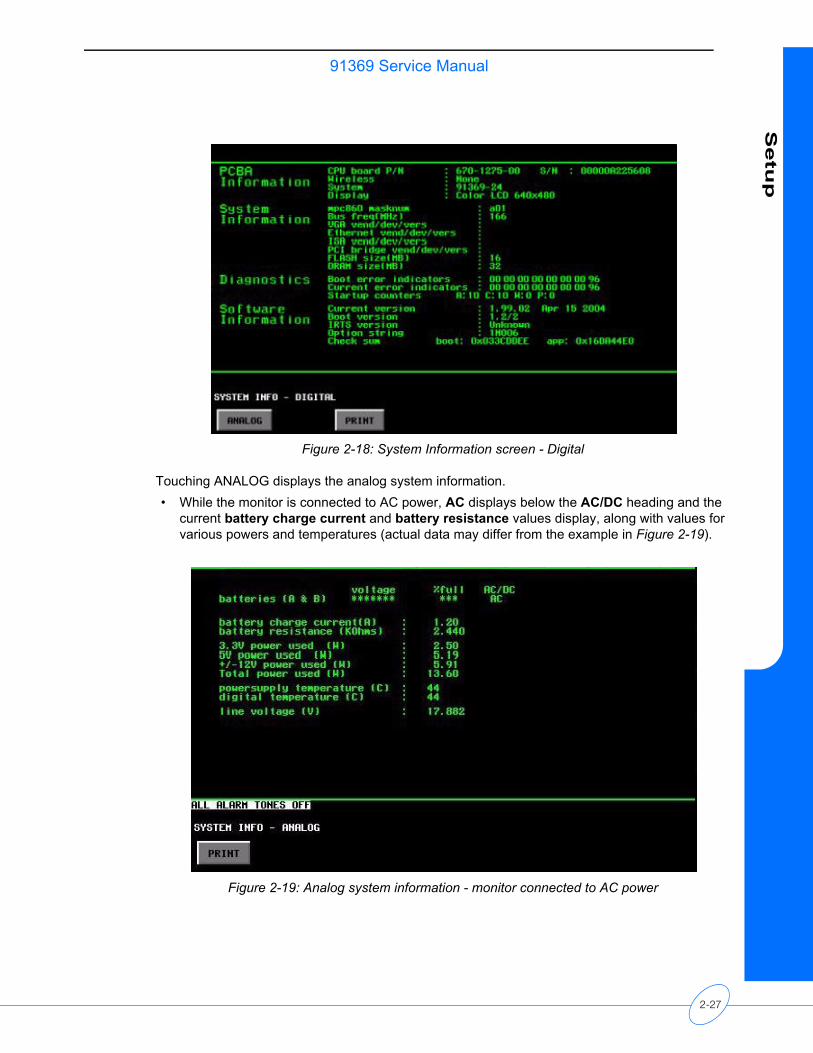
System InformationThe SYSTEM INFO key in the Biomed Level menu accesses the monitor’s System Information - Digital screen (actual data may differ from the example in Figure 2-18).
2-26
91369 Service ManualS
etu
p
Figure 2-18: System Information screen - Digital
Touching ANALOG displays the analog system information. • While the monitor is connected to AC power, AC displays below the AC/DC heading and the
current battery charge current and battery resistance values display, along with values for various powers and temperatures (actual data may differ from the example in Figure 2-19).
Figure 2-19: Analog system information - monitor connected to AC power
2-27
91369 Service Manual
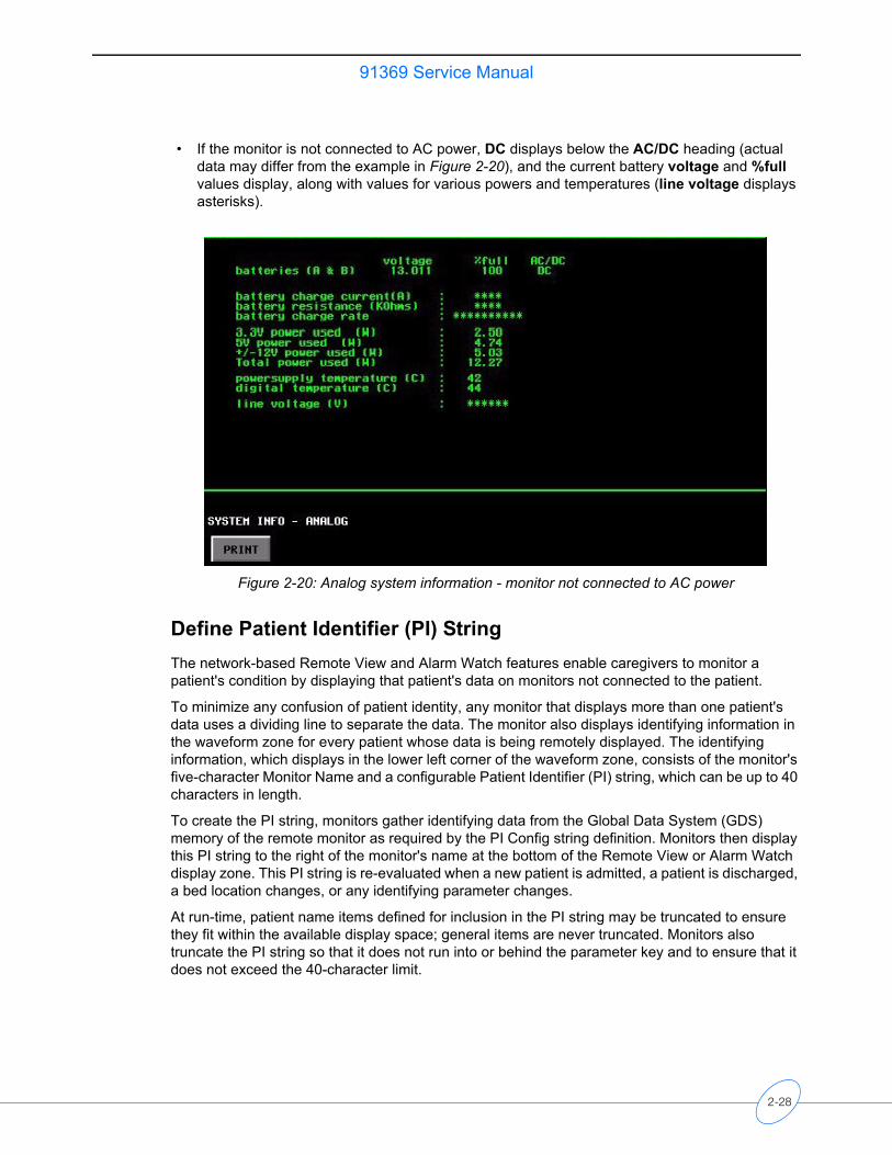
• If the monitor is not connected to AC power, DC displays below the AC/DC heading (actual data may differ from the example in Figure 2-20), and the current battery voltage and %full values display, along with values for various powers and temperatures (line voltage displays asterisks).
Figure 2-20: Analog system information - monitor not connected to AC power
Define Patient Identifier (PI) StringThe network-based Remote View and Alarm Watch features enable caregivers to monitor a patient's condition by displaying that patient's data on monitors not connected to the patient.
To minimize any confusion of patient identity, any monitor that displays more than one patient's data uses a dividing line to separate the data. The monitor also displays identifying information in the waveform zone for every patient whose data is being remotely displayed. The identifying information, which displays in the lower left corner of the waveform zone, consists of the monitor's five-character Monitor Name and a configurable Patient Identifier (PI) string, which can be up to 40 characters in length.
To create the PI string, monitors gather identifying data from the Global Data System (GDS) memory of the remote monitor as required by the PI Config string definition. Monitors then display this PI string to the right of the monitor's name at the bottom of the Remote View or Alarm Watch display zone. This PI string is re-evaluated when a new patient is admitted, a patient is discharged, a bed location changes, or any identifying parameter changes.
At run-time, patient name items defined for inclusion in the PI string may be truncated to ensure they fit within the available display space; general items are never truncated. Monitors also truncate the PI string so that it does not run into or behind the parameter key and to ensure that it does not exceed the 40-character limit.
2-28
91369 Service ManualS
etu
p
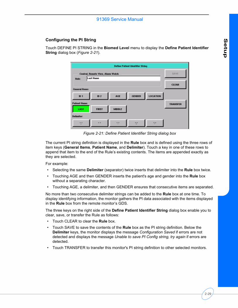
Configuring the PI String
Touch DEFINE PI STRING in the Biomed Level menu to display the Define Patient Identifier String dialog box (Figure 2-21).
Figure 2-21: Define Patient Identifier String dialog box
The current PI string definition is displayed in the Rule box and is defined using the three rows of item keys (General Items, Patient Name, and Delimiter). Touch a key in one of these rows to append that item to the end of the Rule’s existing contents. The items are appended exactly as they are selected.
For example:• Selecting the same Delimiter (separator) twice inserts that delimiter into the Rule box twice. • Touching AGE and then GENDER inserts the patient's age and gender into the Rule box
without a separating character. • Touching AGE, a delimiter, and then GENDER ensures that consecutive items are separated.
No more than two consecutive delimiter strings can be added to the Rule box at one time. To display identifying information, the monitor gathers the PI data associated with the items displayed in the Rule box from the remote monitor’s GDS.
The three keys on the right side of the Define Patient Identifier String dialog box enable you to clear, save, or transfer the Rule as follows:• Touch CLEAR to clear the Rule box. • Touch SAVE to save the contents of the Rule box as the PI string definition. Below the
Delimiter keys, the monitor displays the message Configuration Saved if errors are not detected and displays the message Unable to save PI Config string, try again if errors are detected.
• Touch TRANSFER to transfer this monitor's PI string definition to other selected monitors.
2-29
91369 Service Manual
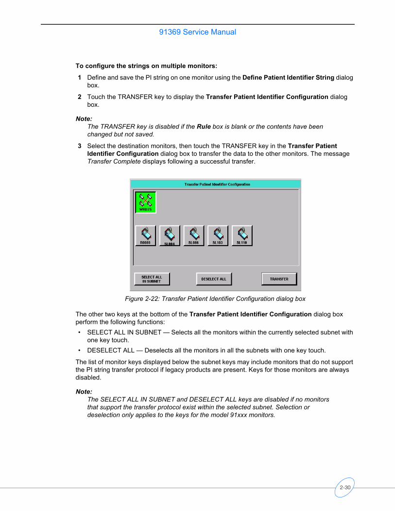
To configure the strings on multiple monitors:
1 Define and save the PI string on one monitor using the Define Patient Identifier String dialog box.
2 Touch the TRANSFER key to display the Transfer Patient Identifier Configuration dialog box.
Note:The TRANSFER key is disabled if the Rule box is blank or the contents have been changed but not saved.
3 Select the destination monitors, then touch the TRANSFER key in the Transfer Patient Identifier Configuration dialog box to transfer the data to the other monitors. The message Transfer Complete displays following a successful transfer.
Figure 2-22: Transfer Patient Identifier Configuration dialog box
The other two keys at the bottom of the Transfer Patient Identifier Configuration dialog box perform the following functions:• SELECT ALL IN SUBNET — Selects all the monitors within the currently selected subnet with
one key touch. • DESELECT ALL — Deselects all the monitors in all the subnets with one key touch.
The list of monitor keys displayed below the subnet keys may include monitors that do not support the PI string transfer protocol if legacy products are present. Keys for those monitors are always disabled.
Note:The SELECT ALL IN SUBNET and DESELECT ALL keys are disabled if no monitors that support the transfer protocol exist within the selected subnet. Selection or deselection only applies to the keys for the model 91xxx monitors.
2-30
91369 Service ManualS
etu
p
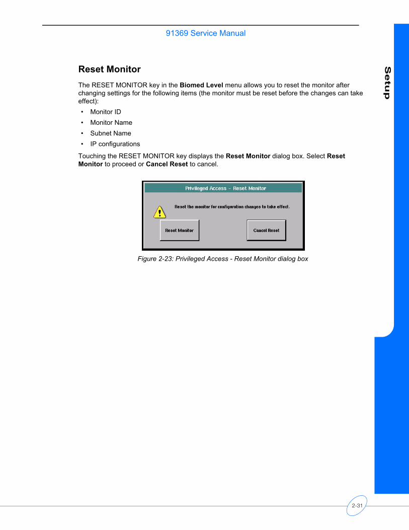
Reset MonitorThe RESET MONITOR key in the Biomed Level menu allows you to reset the monitor after changing settings for the following items (the monitor must be reset before the changes can take effect):• Monitor ID• Monitor Name• Subnet Name• IP configurations
Touching the RESET MONITOR key displays the Reset Monitor dialog box. Select Reset Monitor to proceed or Cancel Reset to cancel.
Figure 2-23: Privileged Access - Reset Monitor dialog box
2-31

Theory
Contents
Overview . . . . . . . . . . . . . . . . . . . . . . . . . . . . . . . . . . . . . . . . . . . . . . . . . . . . . . . . . . . 1Major System Components . . . . . . . . . . . . . . . . . . . . . . . . . . . . . . . . . . . . . . . . . . . . . 1Printed Circuit Board Assemblies (PCBAs) . . . . . . . . . . . . . . . . . . . . . . . . . . . . . . . . . 4Interconnect and Connector PCBAs . . . . . . . . . . . . . . . . . . . . . . . . . . . . . . . . . . . . . 14Bezel Assembly . . . . . . . . . . . . . . . . . . . . . . . . . . . . . . . . . . . . . . . . . . . . . . . . . . . . . 15Boot Sequence Overview . . . . . . . . . . . . . . . . . . . . . . . . . . . . . . . . . . . . . . . . . . . . . 17Normal Operation Overview . . . . . . . . . . . . . . . . . . . . . . . . . . . . . . . . . . . . . . . . . . . 17Display. . . . . . . . . . . . . . . . . . . . . . . . . . . . . . . . . . . . . . . . . . . . . . . . . . . . . . . . . . . . 18Parameter Modules . . . . . . . . . . . . . . . . . . . . . . . . . . . . . . . . . . . . . . . . . . . . . . . . . . 19CPU PCBA Connectors . . . . . . . . . . . . . . . . . . . . . . . . . . . . . . . . . . . . . . . . . . . . . . . 20CPU PCBA Jumpers . . . . . . . . . . . . . . . . . . . . . . . . . . . . . . . . . . . . . . . . . . . . . . . . . 20I/O PCBA Connectors . . . . . . . . . . . . . . . . . . . . . . . . . . . . . . . . . . . . . . . . . . . . . . . . 21Interconnect PCBA Connectors. . . . . . . . . . . . . . . . . . . . . . . . . . . . . . . . . . . . . . . . . 21Overview
A typical monitor configuration consists of these major components:• Monitor• DC power supply• Parameter module
There may also be additional hardware devices present, such as a mouse, keyboard, and barcode scanner.
The monitor may also be used in conjunction with other hardware components, such as:• 90491/90499 module housings• Flexport system interface• Gas analyzer• External display
Major System Components
Main EnclosureThe main enclosure includes the CPU, Interconnect, and I/O PCBAs, with one integrated module slot. The main enclosure does not include an AC-to-DC power supply. AC-to-DC power conversion is provided by an external DC supply. The external supply provides 18 VDC, which is internally converted to generate appropriate operating voltages.
3-1
91369 Service Manual
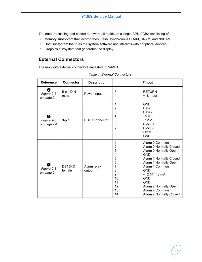
The data processing and control hardware all reside on a single CPU PCBA consisting of:• Memory subsystem that incorporates Flash, synchronous DRAM, SRAM, and NVRAM.• Host subsystem that runs the system software and interacts with peripheral devices.• Graphics subsystem that generates the display.
External ConnectorsThe monitor’s external connectors are listed in Table 1.
Table 1: External Connectors
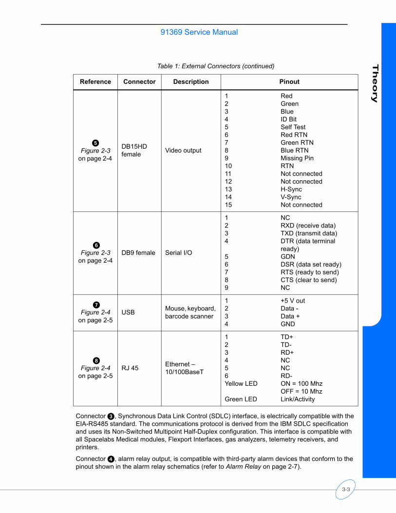
Reference Connector Description Pinout
�Figure 2-3
on page 2-4
5-pin DINmale Power input 3 RETURN
4 +18 Input
�Figure 2-3
on page 2-49-pin SDLC connector
1 GND2 Data +3 Data -4 +5 V5 +12 V6 Clock +7 Clock -8 -12 V9 GND
�Figure 2-3
on page 2-4
DB15HD female
Alarm relay output
1 Alarm 0 Common2 Alarm 0 Normally Closed3 Alarm 0 Normally Open4 GND5 Alarm 1 Normally Closed6 Alarm 1 Normally Open7 Alarm 1 Common8 GND9 +12 @ 140 mA10 GND11 GND12 Alarm 2 Normally Open13 Alarm 2 Common14 Alarm 2 Normally Closed
3-2
91369 Service ManualT
heo
ry
Connector �, Synchronous Data Link Control (SDLC) interface, is electrically compatible with the EIA-RS485 standard. The communications protocol is derived from the IBM SDLC specification and uses its Non-Switched Multipoint Half-Duplex configuration. This interface is compatible with all Spacelabs Medical modules, Flexport Interfaces, gas analyzers, telemetry receivers, and printers.
Connector �, alarm relay output, is compatible with third-party alarm devices that conform to the pinout shown in the alarm relay schematics (refer to Alarm Relay on page 2-7).
�Figure 2-3
on page 2-4
DB15HD female Video output
1 Red2 Green3 Blue4 ID Bit5 Self Test6 Red RTN7 Green RTN8 Blue RTN9 Missing Pin10 RTN11 Not connected12 Not connected13 H-Sync14 V-Sync15 Not connected
�Figure 2-3
on page 2-4DB9 female Serial I/O
1 NC2 RXD (receive data)3 TXD (transmit data)4 DTR (data terminal
ready)5 GDN6 DSR (data set ready)7 RTS (ready to send)8 CTS (clear to send)9 NC
�Figure 2-4
on page 2-5USB Mouse, keyboard,
barcode scanner
1 +5 V out2 Data -3 Data +4 GND
�Figure 2-4
on page 2-5RJ 45 Ethernet –
10/100BaseT
1 TD+2 TD-3 RD+4 NC5 NC6 RD-Yellow LED ON = 100 Mhz
OFF = 10 MhzGreen LED Link/Activity
Table 1: External Connectors (continued)
Reference Connector Description Pinout
3-3
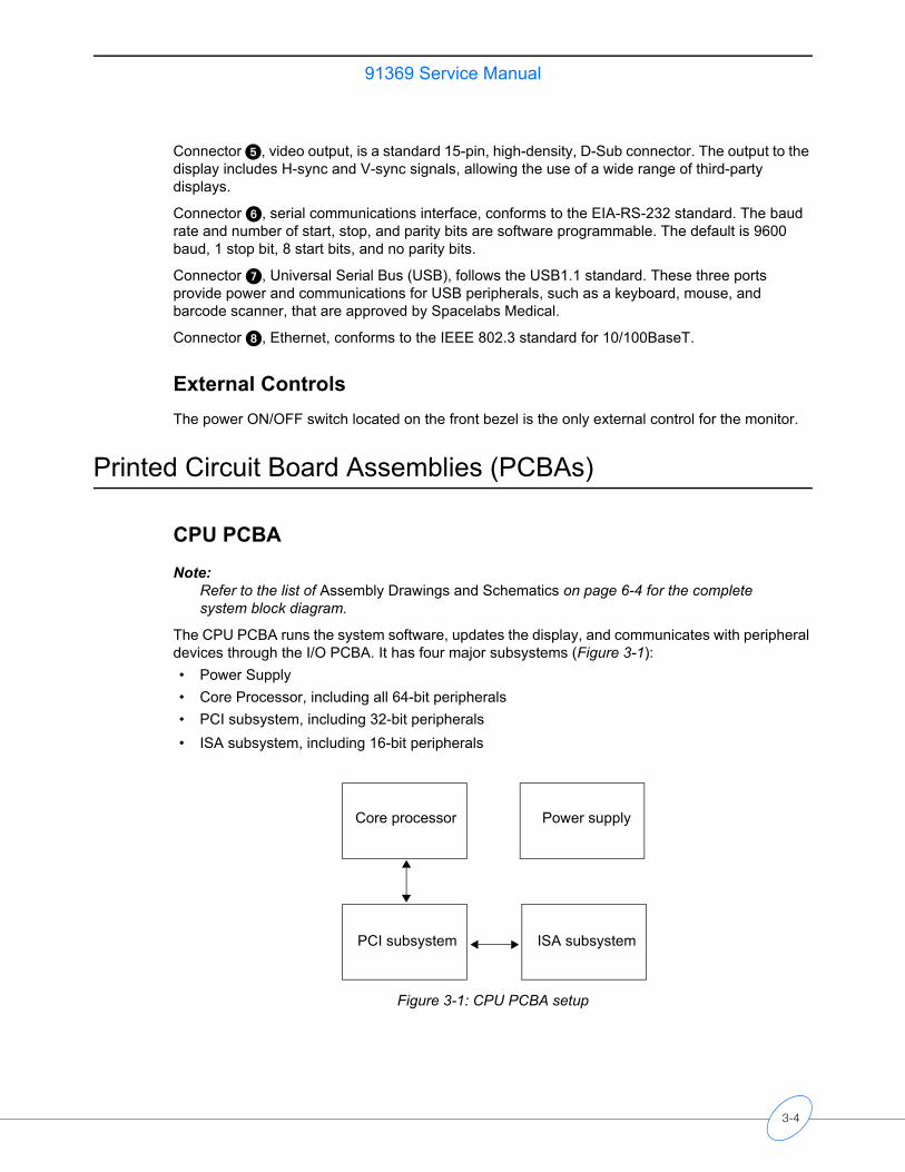
91369 Service Manual
Connector �, video output, is a standard 15-pin, high-density, D-Sub connector. The output to the display includes H-sync and V-sync signals, allowing the use of a wide range of third-party displays.
Connector �, serial communications interface, conforms to the EIA-RS-232 standard. The baud rate and number of start, stop, and parity bits are software programmable. The default is 9600 baud, 1 stop bit, 8 start bits, and no parity bits.
Connector �, Universal Serial Bus (USB), follows the USB1.1 standard. These three ports provide power and communications for USB peripherals, such as a keyboard, mouse, and barcode scanner, that are approved by Spacelabs Medical.
Connector �, Ethernet, conforms to the IEEE 802.3 standard for 10/100BaseT.
External ControlsThe power ON/OFF switch located on the front bezel is the only external control for the monitor.
Printed Circuit Board Assemblies (PCBAs)
CPU PCBA
Note:Refer to the list of Assembly Drawings and Schematics on page 6-4 for the complete system block diagram.
The CPU PCBA runs the system software, updates the display, and communicates with peripheral devices through the I/O PCBA. It has four major subsystems (Figure 3-1):• Power Supply • Core Processor, including all 64-bit peripherals• PCI subsystem, including 32-bit peripherals• ISA subsystem, including 16-bit peripherals
Figure 3-1: CPU PCBA setup
Core processor Power supply
PCI subsystem ISA subsystem
3-4
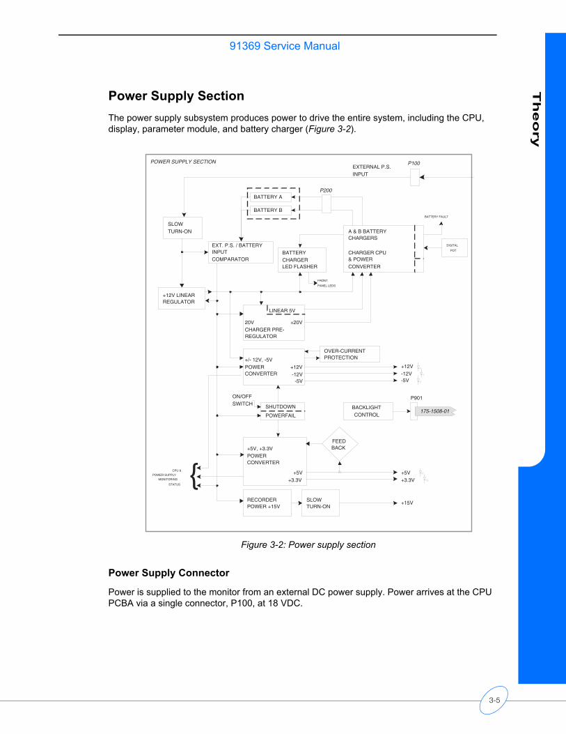
91369 Service ManualT
heo
ry
Power Supply SectionThe power supply subsystem produces power to drive the entire system, including the CPU, display, parameter module, and battery charger (Figure 3-2).
Figure 3-2: Power supply section
Power Supply Connector
Power is supplied to the monitor from an external DC power supply. Power arrives at the CPU PCBA via a single connector, P100, at 18 VDC.
P901
BACKLIGHTCONTROL
EXT. P.S. / BATTERYINPUTCOMPARATOR
SLOWTURN-ON
+12V LINEARREGULATOR
EXTERNAL P.S.INPUT
BATTERY B
BATTERY A
LINEAR 5V
20VCHARGER PRE-REGULATOR
BATTERYCHARGERLED FLASHER
+/- 12V, -5VPOWERCONVERTER
+12V-12V
-5V
+20V
SHUTDOWN
POWERFAIL
CPU &
POWER SUPPLY
MONITORING
STATUS
+5V, +3.3VPOWERCONVERTER
+5V+3.3V
FEEDBACK
A & B BATTERYCHARGERS
CHARGER CPU& POWERCONVERTER
OVER-CURRENTPROTECTION
FRONT
PANEL LEDS
{RECORDERPOWER +15V
SLOWTURN-ON
+5V+3.3V
+15V
+12V-12V-5V
P100
P200
BATTERY FAULT
DIGITAL
POT
ON/OFFSWITCH
POWER SUPPLY SECTION
175-1508-01
3-5
91369 Service Manual
DC-DC Converters
The internal power supply derives six output voltages for different functions of the CPU PCBA.• +12 V @ 24 W• -12 V @ 1.2 W• -5 V @ 0.5 W• +15 V @ 3 W• +5 V @ 15 W• +3.3 V @ 6 W
In the event of mains power failure, all supplies are maintained through power derived from up to two internal 12 V NiMH batteries.
The power supply subsection has a slow turn-on feature, which prevents high inrush currents when power is switched ON. The power supply will also control which input source to use, either the external power supply or the batteries. The minimum input voltage required to operate the monitor is 11.5 VDC. If the external power supply input is less than 11.5 VDC, and the batteries greater than 10.75 VDC, the monitor will run on battery power.
Power Failure Operation
The power supply on the CPU PCBA provides a digital signal PFAIL to the CPU to indicate that a power failure condition is imminent. This signal is asserted by the power supply if its input power fails, or if the monitor is switched OFF. This signal is provided through a power supervisor IC to the MPC8270 as an interrupt, causing the processor to take immediate power failure action.
Power failure operation of the monitor takes advantage of the fact that this monitor’s design requires at least one charged battery to be present at all times. This battery provides power for the monitor far in excess of the intended three-minute data retention requirement for the module data.
Battery Chargers
The battery chargers have the following features:• Front panel LED battery charging/failure indicator.• Automatic “battery care” recharge cycles to ensure a maximum charge.• Individual battery chargers for each of the two batteries, so that a bad battery will not degrade
the other battery.• If the monitor is OFF, one or two batteries can be fully charged in 90-120 minutes. If the
monitor is ON, batteries are charged in four to five hours.
Charger Pre-Regulator — The +20 VDC output provides up to 60 W of battery charging power. This DC output voltage is then used as the main power source for charging batteries. The circuit uses a single-ended flyback converter topology. This pre-regulator circuit is active at all times when the monitor is powered from the external power supply voltage.
Charger CPU IC — This IC is a pre-programmed microprocessor designed specifically for controlling the charging of batteries. The CPU monitors the voltage and resistance of the batteries while charging and determines when to turn the charger power converter ON or OFF, and can detect faulty batteries. The CPU periodically performs maintenance cycles to keep batteries fully charged.
3-6
91369 Service ManualT
heo
ry
Charger Power Converter — The power converter consists of a LT1511 step-down converter and various discrete components. It is turned ON and OFF under the control of the charger CPU IC. When ON, it charges the batteries with the maximum current that is allowed by the charge rate control circuit.
Charge Rate Control — The minimum battery charge rate is always controlled by the battery itself. A battery will only accept the current it is capable of converting to charge inside the cells. However, the control for the maximum battery charge current is controlled in one of two ways. If the monitor is powered from the power supply and the front panel power switch is OFF, the maximum charge current defaults to the maximum current that the batteries can take, which is 1.8 A. If the monitor is powered from the AC/DC power supply and the front panel power switch is ON, the CPU will have control of the maximum battery charge rate via an analog switch and digital potentiometer. The CPU monitors the power consumed by the monitor electronics and adjusts the charge current based on the amount of remaining power available from the power supply.
Battery Charging LEDs — A pair of simple op-amp oscillator circuits controls the operation of the two front panel battery charge status LEDs. When either battery is charging, a signal from the charging circuit causes that battery's oscillator to run, which causes the corresponding front panel LED to flash. The two front panel battery charge status LEDs are independent of the front panel power LED. When external power is available, the power LED is constantly lit; this LED is off when external power is not available.
Battery Fault/Interrupt Signal — If the battery voltage exceeds the upper limit, the charger CPU IC will power OFF the charger and then attempt to charge again. If the battery voltage exceeds the upper limit again, a 1 Hz signal will be sent to an MPC8270 CPU interrupt input (via the ISA bridge). The software will sense this 1 Hz rate and will indicate a battery failure. If the battery voltage is too low, the process is the same.
Automatic Fan Control — The MPC8270 CPU monitors internal temperature via temperature sensors and an A/D. If the temperature exceeds a preset limit, the CPU will run the fan at a normal speed until the temperature is reduced. However, during battery charging, the battery chargers override the CPU and force the fan on at a higher than normal speed. This allows the battery chargers to run at full output without overheating the unit.
Note:The fan will not operate unless a battery is installed.
Core Processor SubsystemThe core processor subsystem includes a memory subsystem and a microprocessor subsystem (Figure 3-3). The memory subsystem incorporates Flash ROM, Synchronous DRAM (SDRAM), and Static RAM on the local 60x bus. All are directly controlled by the memory controller of the MPC8270 microprocessor.
3-7
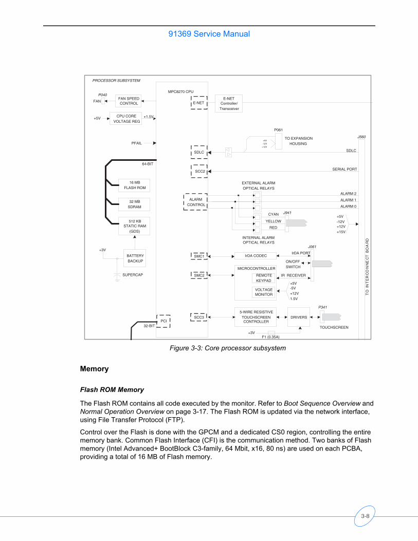
91369 Service Manual
Figure 3-3: Core processor subsystem
Memory
Flash ROM Memory
The Flash ROM contains all code executed by the monitor. Refer to Boot Sequence Overview and Normal Operation Overview on page 3-17. The Flash ROM is updated via the network interface, using File Transfer Protocol (FTP).
Control over the Flash is done with the GPCM and a dedicated CS0 region, controlling the entire memory bank. Common Flash Interface (CFI) is the communication method. Two banks of Flash memory (Intel Advanced+ BootBlock C3-family, 64 Mbit, x16, 80 ns) are used on each PCBA, providing a total of 16 MB of Flash memory.
MPC8270 CPU
64-BIT
SCC2
16 MBFLASH ROM
32 MBSDRAM
512 KBSTATIC RAM
(GDS)
SDLC
PFAIL
PROCESSOR SUBSYSTEM
SUPERCAP
E-NETController/
Transceiver
E-NET
+5V
-12V
+12V
TO EXPANSIONHOUSING
IrDA CODECIrDA PORT
SMC1
IR RECEIVERREMOTEKEYPAD
MICROCONTROLLER
J061
+5V-5V+12V1.5V
VOLTAGEMONITOR
SCC35-WIRE RESISTIVE
TOUCHSCREENCONTROLLER
DRIVERS
+3VTOUCHSCREEN
P341
ALARMCONTROL
EXTERNAL ALARMOPTICAL RELAYS
INTERNAL ALARMOPTICAL RELAYS
F1 (0.35A)
J941
J560
FAN SPEEDCONTROL
P040
BATTERYBACKUP
+3V
PCI
CPU COREVOLTAGE REG
+5V +1.5V
P061
ON/OFFSWITCH
+5V-12V+12V+15V
CYAN
YELLOW
RED
ALARM 2
ALARM 1
ALARM 0
SERIAL PORT
SDLC
TO
IN
TE
RC
ON
NE
CT
BO
AR
D
SMC2
32-BIT
FAN
3-8
91369 Service ManualT
heo
ry
SDRAM Memory
In Normal Operation, the CPU executes code directly from SDRAM.
The 32 MB (256 Mbits) SDRAM is refreshed using its auto-refresh mode. Using the SDRAM’s periodic timer, an auto refresh command is issued to the SDRAM every 15.6 µs.
Static RAM (GDS) Memory
The Static RAM contains Patient Trend Data and Demographics, known as the Global Data System (GDS).
The monitor contains two banks of 256 KB SRAM that hold the GDS data. They draw their power from the 3 V backup with a minimum of three minutes of battery backup supply, using a SuperCap with the MAXIM 6363 supervisor.
Chip Selects
Chip selects for devices on the 60x bus are generated by the MPC8270 memory controller unit. The monitor uses only three of the 12 available chip selects:• CS0 — Boot Flash (controlled by the GPCM)• CS2 — SDRAM (controlled by the SDRAM)• CS6 — GDS SRAM (controlled by the GPCM)
MPC8270 Microprocessor
The monitor uses the Motorola MPC8270ZQ processor. Some of the special features include:• PowerPC G2_LE core processor unit.• Separate power supply for the internal logic (1.5 V) and for I/O (3.3 V).• 64-bit data and 32-bit address on the 60x bus.• 32-bit address/data on the PCI bus.• Integrated PCI 2.2 compliant bridge, 32-bit data bus, 66 MHz, 3.3 V.• Twelve-bank memory controller with glueless interface to SRAM, SG1DRAM, and Flash.• Embedded 32-bit RISC architecture communication processor.
Ethernet Interface
The MPC8270 contains fast ports on its communication module. The monitor takes advantage of one FCC port (FCC1) for the 10/100BaseT Ethernet port. The interface to the Physical Layer (PHY) is through full Media Independent Interface (MII). Data communication is in Nibble mode (4 TX_D lines and 4 RX_D lines). The RJ-45 connector contains LEDs indicating speed (yellow ON for 100MHz, yellow OFF for 10MHz) and link status (green flashing about once every five seconds for Link Active).
3-9
91369 Service Manual
MII
The MPC8270 has all the MII pins except bi-directional data line (MDIO) and MDC (clock), which are provided between the PHY chip and MPC8270 GPIO.• MDIO → PC4• MDC → PC3
Fast Ethernet PHY
An Intel LXT972A is used for Ethernet PHY. This is an IEEE-compliant Fast Ethernet PHY transceiver supporting both 10BaseT and 100BaseT applications.
SDLC Interface
The SDLC bus is the communications interface to Spacelabs Medical modules, which supply patient data to the monitors. The SDLC interface runs at 1.892352 MHz. This is divided down to generate a 448 Hz sampling rate. The SDLC communication task retrieves the data from the bus, assembles it into a packet format, and provides it to the monitor application. The SDLC clock signals are output by the SDLC interface and are used to drive the external SDLC bus and modules. The SDLC data signals are bi-directional and can be used to both transmit and receive data from the intelligent modules.
RS-232 (UART)
The RS-232 universal asynchronous receiver-transmitter (UART) uses some UART signals for communication with external devices. Linear Technology LTC1331 RS-232 transceivers are used to provide 3 V interface with the MPC8270. Communication with external RS-232 devices is through the 9-pin DSUB connector and transmission speed is limited to 9600 Kbps.
Embedded Alarm Light
A “flexible circuit” and PCBA contain circuitry for the embedded alarm light. Five ultra-bright LEDs are used for each color (red, yellow, and cyan) to generate the back light for the lens.
Because alarms are available on the monitor as well as externally, an internal signal is provided (from pin PB26 on the MPC8270), allowing the software to enable/disable the embedded alarm light on the monitor.
At initial power on, the LEDs cycle through at a rate of 4.2 Hz for a duration of two seconds, which is more rapid than the fastest flash rate used for any alarm condition (2.8 Hz). This function allows the user to confirm that all the LEDs are functional.
Optical relays are used for both the embedded alarm light and the external alarm relay output.
External Alarm Control
During boot diagnostics, all three alarm relays are tested for two seconds. During normal operation, the high-priority alarm relay is activated during high-priority alarms (for example, heart rate), and the medium-priority alarm relay is activated during medium-priority alarms (for example, leads off).
3-10
91369 Service ManualT
heo
ry
Remote Keypad (Optional)
The monitor supports the 90360 remote keypad. The communication from the keypad is through 940 nm wavelength infrared, and processing is done in the Motorola MC68HC908 8-bit microcontroller.
Touchscreen Circuitry
An ELO Graphics Coach chip set is built into the CPU PCBA to handle all communication between the 5-wire resistive matrix touchscreen and the MPC8270 CPU. In addition to the standard UART signals, additional signals from the on-board touchscreen controller (touchscreen sense, wake up, and shutdown) are directly routed to the MPC8270 GPIOs. The current drivers for the touchscreen are sourced from +3 VDC through fuse F1.
Hardware Reset
Externally driven HRESET* will cause the following:• Initialize memory controller• Initialize system protection logic• Initialize interrupt controller• Initialize parallel I/O pins
PCI SubsystemThe PCI subsystem interfaces directly to the PCI Bridge integrated into the MPC8270 processor (Figure 3-4). All accesses to the PCI devices are done through this bridge. The monitor supports up to five PCI devices, not including the PCI module integrated into the MPC8270. Not all devices reside on the primary PCI bus. To keep the design modular and simple, only the PCI/ISA bridge, PCI/PCI bridge, and video controller reside on the primary PCI bus. The PCMCIA controller is placed on the secondary PCI bus through the PC/PCI bridge. The USB keyboard and mouse are supported by a USB controller located within the Intel 82371, which is USB v1.1 compliant.
3-11
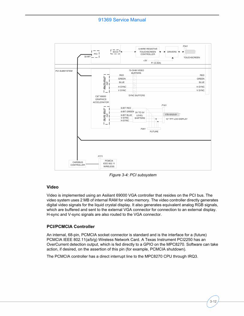
91369 Service Manual
Figure 3-4: PCI subsystem
Video
Video is implemented using an Asiliant 69000 VGA controller that resides on the PCI bus. The video system uses 2 MB of internal RAM for video memory. The video controller directly generates digital video signals for the liquid crystal display. It also generates equivalent analog RGB signals, which are buffered and sent to the external VGA connector for connection to an external display. H-sync and V-sync signals are also routed to the VGA connector.
PCI/PCMCIA Controller
An internal, 68-pin, PCMCIA socket connector is standard and is the interface for a (future) PCMCIA IEEE 802.11(a/b/g) Wireless Network Card. A Texas Instrument PCI2250 has an OverCurrent detection output, which is fed directly to a GPIO on the MPC8270. Software can take action, if desired, on the assertion of this pin (for example, PCMCIA shutdown).
The PCMCIA controller has a direct interrupt line to the MPC8270 CPU through IRQ3.
RED
GREEN
BLUE
H SYNC
V SYNC
75-OHM VIDEOBUFFERS
SYNC BUFFERS
SCC35-WIRE RESISTIVE
TOUCHSCREENCONTROLLER
DRIVERS
+3VTOUCHSCREEN
P341
F1 (0.35A)
PCMCIAIEEE 802.11WIRELESS
CARDBUSCONTROLLER
PCI
C&T 69000GRAPHICS
ACCELERATORAN
ALO
G VI
DEO
OUT
10" TFT LCD DISPLAY
6-BIT GREEN
6-BIT RED
6-BIT BLUEV-SYNCH-SYNCDI
GIT
AL V
IDEO
OUT
P261
3V TO 5VLEVEL
SHIFTERS
FUTURE
P161
PCI SUBSYSTEM
P771
175-1012-01
32-BIT
RED
GREEN
BLUE
H SYNC
V SYNC
3-12
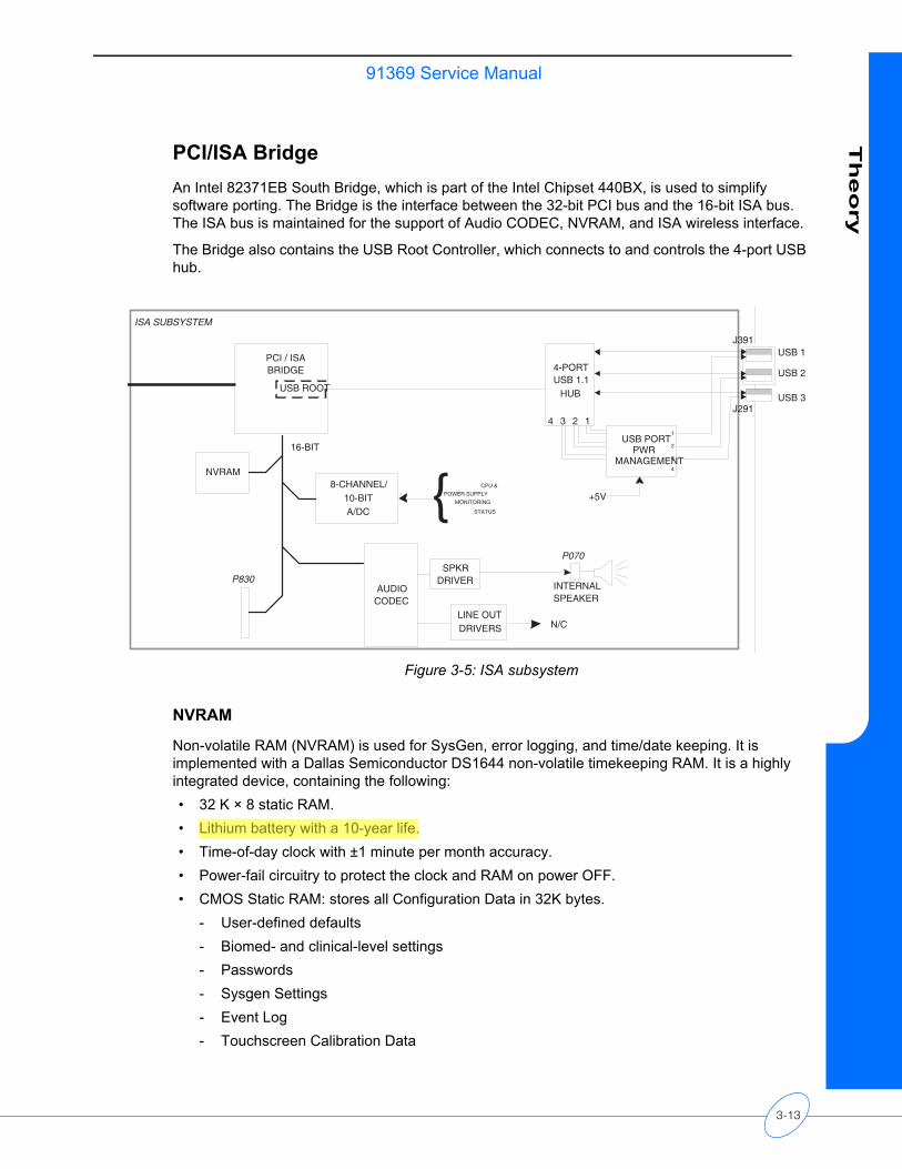
91369 Service ManualT
heo
ry
PCI/ISA BridgeAn Intel 82371EB South Bridge, which is part of the Intel Chipset 440BX, is used to simplify software porting. The Bridge is the interface between the 32-bit PCI bus and the 16-bit ISA bus. The ISA bus is maintained for the support of Audio CODEC, NVRAM, and ISA wireless interface.
The Bridge also contains the USB Root Controller, which connects to and controls the 4-port USB hub.
Figure 3-5: ISA subsystem
NVRAM
Non-volatile RAM (NVRAM) is used for SysGen, error logging, and time/date keeping. It is implemented with a Dallas Semiconductor DS1644 non-volatile timekeeping RAM. It is a highly integrated device, containing the following:• 32 K × 8 static RAM.• Lithium battery with a 10-year life.• Time-of-day clock with ±1 minute per month accuracy.• Power-fail circuitry to protect the clock and RAM on power OFF.• CMOS Static RAM: stores all Configuration Data in 32K bytes.
- User-defined defaults- Biomed- and clinical-level settings- Passwords- Sysgen Settings- Event Log- Touchscreen Calibration Data
USB 1
USB 2
USB 3
4-PORTUSB 1.1
HUB
USB PORTPWR
MANAGEMENT
12341
2
3
4
+5V
J391
J291
AUDIOCODEC
INTERNALSPEAKER
SPKRDRIVER
LINE OUTDRIVERS
PCI / ISABRIDGE
USB ROOT
NVRAM
P070
8-CHANNEL/10-BITA/DC
P830
N/C
{ CPU &
POWER SUPPLY
MONITORING
STATUS
ISA SUBSYSTEM
16-BIT
3-13
91369 Service Manual
Eight-Channel ADC
The 8-channel, 10-bit ADC is used to monitor power supply functions, including voltage and temperature.
Audio CODEC
An Analog Devices AD1845 produces the sound generation for the monitor. It drives an amplifier for the internal speaker. Line Out functionality is not currently supported.
Interconnect and Connector PCBAs
The Interconnect PCBA plugs directly into the CPU PCBA via J1 (Figure 3-6). It provides power distribution and EMI filtering for:• (Optional) Recorder• (Optional) Recorder CPU • SDLC (module)
The Interconnect PCBA also provides a signal pass-through to the Connector PCBA, which contains:• Serial Port• Analog Video• External Alarm Relay Output• SDLC
3-14
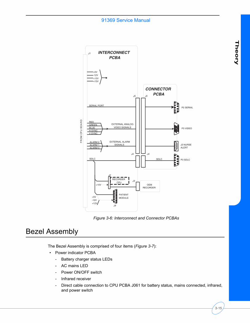
91369 Service ManualT
heo
ry
Figure 3-6: Interconnect and Connector PCBAs
Bezel Assembly
The Bezel Assembly is comprised of four items (Figure 3-7):• Power indicator PCBA
- Battery charger status LEDs- AC mains LED- Power ON/OFF switch- Infrared receiver - Direct cable connection to CPU PCBA J061 for battery status, mains connected, infrared,
and power switch
P2 SERIAL
P3 VIDEO
J3 NURSEALERT
P3 SDLC
CONNECTORPCBA
J4
SDLC
J2
J3RECORDER
CPU
J4
J5J5
J9
SDLC
+5V-12V+12V
REDGREENBLUEH SYNCV SYNC
EXTERNAL ANALOGVIDEO SIGNALS
EXTERNAL ALARMSIGNALS
ALARM 2ALARM 1ALARM 0
SERIAL PORT
+5V-12V+12V+15V
INTERCONNECTPCBA
J1
FR
OM
CP
U B
OA
RD
+15V OEMRECORDER
PATIENTMODULE
3-15

91369 Service Manual
• 10-inch TFT color LCD display- Digital video via direct cable connection from CPU PCBA P161- Backlight power converter - Backlight
• 5-Wire resistive touchscreen- Elo Touchsystems E271-2210 compatible- Direct cable connection to P341 on CPU PCBA
• Embedded alarm light assembly- Direct cable connection to P941 on CPU PCBA - Three banks of LEDs: cyan, yellow and red.
Figure 3-7: Bezel assembly
TO P16110" TFT LCD DISPLAY
BAC
KLIG
HT
INVE
RTO
R
5-WIRE RESISTIVETOUCHSCREEN
BAT A CHARGEBAT B CHARGEMAINS ON
IrDA TXRX
ON/OFFSWITCHTO J061
TO P901
TO P341
BEZEL ASSEMBLY
TO J941CYANYELLOWRED
INTERNAL NURSE ALERT
POWERINDICATORBOARD
650-1301-00
175-1012-01
BACKLIGHT
175-1508-01
1
2
3
IR RECEIVER(REMOTECONTROL)
3-16
91369 Service ManualT
heo
ry
Boot Sequence Overview
When power is applied, the monitor begins its boot-up sequence. The following is a highly abbreviated version of the sequence of events that occurs while the monitor is booting.
1 Program execution starts in Flash ROM.
2 Key internal and external devices and memories are mapped and enabled.
3 The boot-type value is read from Static RAM. This value is written to Static RAM, which is backed up by a “super cap,” at every power-down or self-reboot. The value determines the kind of boot: warm or cold. Warm booting maintains all data, then skips diagnostics and other steps in order to restore monitoring as soon as possible.
4 Key areas of SDRAM are tested (cold boot only).
5 The boot code is copied from Flash ROM to SDRAM, where program execution resumes.
6 More internal and external devices are initialized.
7 Other key memory and CPU tests are performed (cold boot only).
8 Drivers needed for diagnostics and the boot console are installed.
9 Diagnostics are run (cold boot only).
10 Boot screen and the “3-2-1” countdown are displayed (cold boot only).
11 The VxWorks kernel and the application code are copied from Flash ROM to SDRAM, where program execution continues.
12 The VxWorks kernel is started, and all internal and external devices are reinstalled and initialized.
13 The monitor application code is started, and normal monitor operation begins.
Normal Operation Overview
This is a high-level summary of what the software does as part of its normal operation.
Once the monitor is booted, it begins normal monitor operation. Normal operation can be viewed as several high-level software and subsystem tasks running simultaneously. These interface to other tasks, and all the tasks interface to hardware devices via device drivers.
Main Subsystems and TasksThe SDLC subsystem sends packets from the modules to the rest of the system, including Ethernet and GDS, and it also sends packets to modules.
The Interpreter subsystem provides modules and keys with “primitives” that they use, via table code, to create and control their user interface on the monitor. The Keys subsystem handles touchscreen key presses. It receives key presses from the user and notifies the keyboard interpreter, which then runs the appropriate table code program. That program uses the key display task to redraw the new key state as feedback to the user.
The Global Data System (GDS) is the patient database with parameter data from the modules. It contains current, general, trend, and waveform data.
3-17
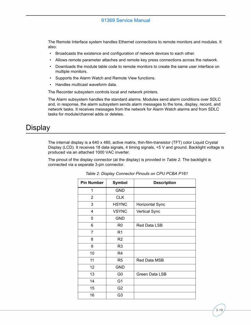
91369 Service Manual
The Remote Interface system handles Ethernet connections to remote monitors and modules. It also:• Broadcasts the existence and configuration of network devices to each other. • Allows remote parameter attaches and remote key press connections across the network.• Downloads the module table code to remote monitors to create the same user interface on
multiple monitors.• Supports the Alarm Watch and Remote View functions.• Handles multicast waveform data.
The Recorder subsystem controls local and network printers.
The Alarm subsystem handles the standard alarms. Modules send alarm conditions over SDLC and, in response, the alarm subsystem sends alarm messages to the tone, display, record, and network tasks. It receives messages from the network for Alarm Watch alarms and from SDLC tasks for module/channel adds or deletes.
Display
The internal display is a 640 x 480, active matrix, thin-film-transistor (TFT) color Liquid Crystal Display (LCD). It receives 18 data signals, 4 timing signals, +5 V and ground. Backlight voltage is produced via an attached 1000 VAC inverter.
The pinout of the display connector (at the display) is provided in Table 2. The backlight is connected via a separate 3-pin connector.
Table 2: Display Connector Pinouts on CPU PCBA P161
Pin Number Symbol Description
1 GND
2 CLK
3 HSYNC Horizontal Sync
4 VSYNC Vertical Sync
5 GND
6 R0 Red Data LSB
7 R1
8 R2
9 R3
10 R4
11 R5 Red Data MSB
12 GND
13 G0 Green Data LSB
14 G1
15 G2
16 G3
3-18
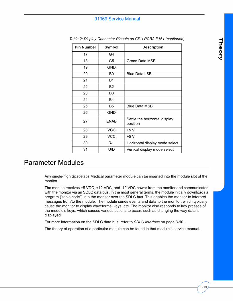
91369 Service ManualT
heo
ry
Parameter Modules
Any single-high Spacelabs Medical parameter module can be inserted into the module slot of the monitor.
The module receives +5 VDC, +12 VDC, and -12 VDC power from the monitor and communicates with the monitor via an SDLC data bus. In the most general terms, the module initially downloads a program (“table code”) into the monitor over the SDLC bus. This enables the monitor to interpret messages from/to the module. The module sends events and data to the monitor, which typically cause the monitor to display waveforms, keys, etc. The monitor also responds to key presses of the module’s keys, which causes various actions to occur, such as changing the way data is displayed.
For more information on the SDLC data bus, refer to SDLC Interface on page 3-10.
The theory of operation of a particular module can be found in that module’s service manual.
17 G4
18 G5 Green Data MSB
19 GND
20 B0 Blue Data LSB
21 B1
22 B2
23 B3
24 B4
25 B5 Blue Data MSB
26 GND
27 ENAB Settle the horizontal display position
28 VCC +5 V
29 VCC +5 V
30 R/L Horizontal display mode select
31 U/D Vertical display mode select
Table 2: Display Connector Pinouts on CPU PCBA P161 (continued)
Pin Number Symbol Description
3-19
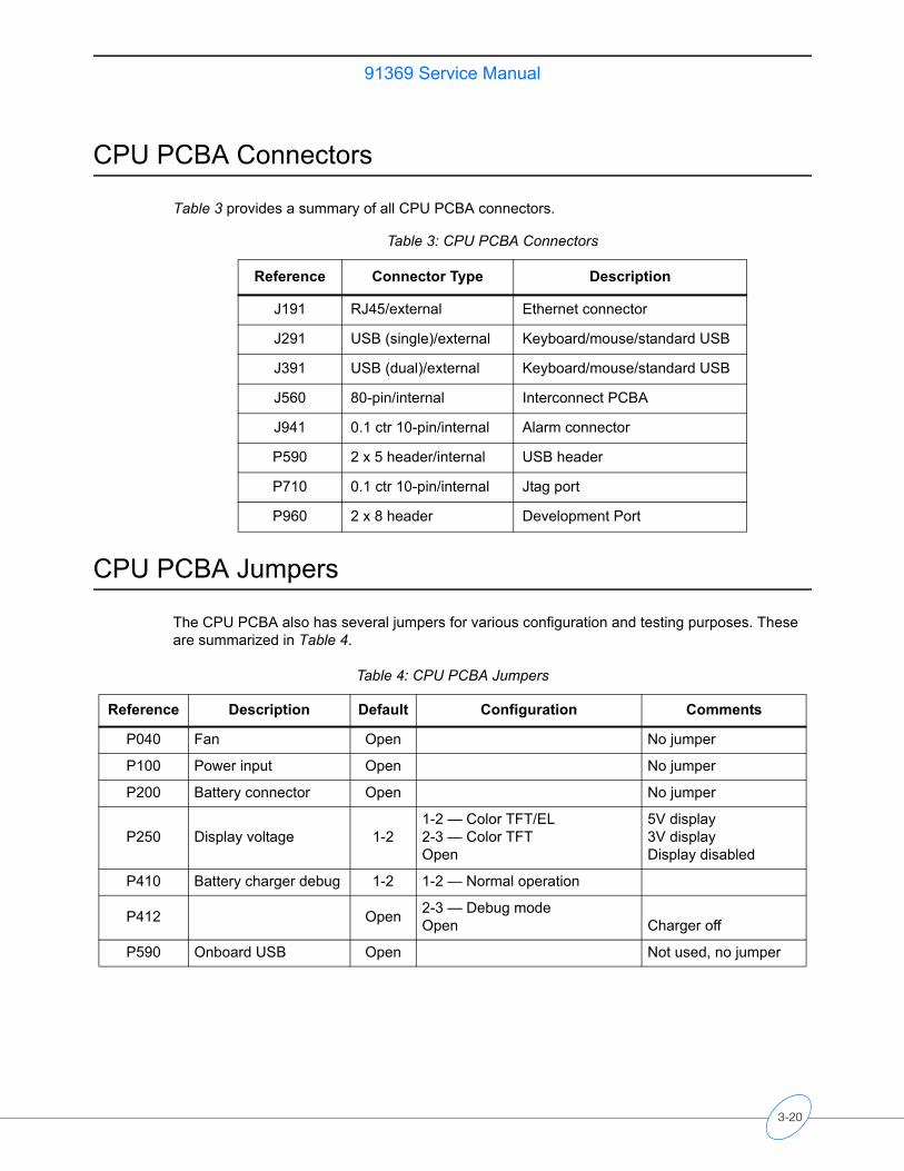
91369 Service Manual
CPU PCBA Connectors
Table 3 provides a summary of all CPU PCBA connectors.
CPU PCBA Jumpers
The CPU PCBA also has several jumpers for various configuration and testing purposes. These are summarized in Table 4.
Table 3: CPU PCBA Connectors
Reference Connector Type Description
J191 RJ45/external Ethernet connector
J291 USB (single)/external Keyboard/mouse/standard USB
J391 USB (dual)/external Keyboard/mouse/standard USB
J560 80-pin/internal Interconnect PCBA
J941 0.1 ctr 10-pin/internal Alarm connector
P590 2 x 5 header/internal USB header
P710 0.1 ctr 10-pin/internal Jtag port
P960 2 x 8 header Development Port
Table 4: CPU PCBA Jumpers
Reference Description Default Configuration Comments
P040 Fan Open No jumper
P100 Power input Open No jumper
P200 Battery connector Open No jumper
P250 Display voltage 1-21-2 — Color TFT/EL2-3 — Color TFTOpen
5V display3V displayDisplay disabled
P410 Battery charger debug 1-2 1-2 — Normal operation
P412 Open 2-3 — Debug modeOpen Charger off
P590 Onboard USB Open Not used, no jumper
3-20
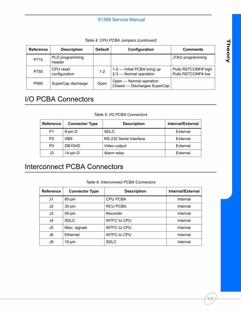
91369 Service ManualT
heo
ry
I/O PCBA Connectors
Interconnect PCBA Connectors
P710 PLD programming header
JTAG programming
P750 CPU reset configuration 1-2 1-2 — Initial PCBA bring up
2-3 — Normal operationPulls RSTCONF# highPulls RSTCONF# low
P990 SuperCap discharge Open Open — Normal operationClosed — Discharges SuperCap
Table 5: I/O PCBA Connectors
Reference Connector Type Description Internal/External
P1 9-pin D SDLC External
P2 DB9 RS-232 Serial Interface External
P3 DB15HD Video output External
J3 14-pin D Alarm relay External
Table 6: Interconnect PCBA Connectors
Reference Connector Type Description Internal/External
J1 80-pin CPU PCBA Internal
J2 30-pin RCU PCBA Internal
J3 50-pin Recorder Internal
J4 SDLC INTFC to CPU Internal
J5 Misc. signals INTFC to CPU Internal
J6 Ethernet INTFC to CPU Internal
J9 15-pin SDLC Internal
Table 4: CPU PCBA Jumpers (continued)
Reference Description Default Configuration Comments
3-21

Maintenance
Contents
Overview . . . . . . . . . . . . . . . . . . . . . . . . . . . . . . . . . . . . . . . . . . . . . . . . . . . . . . . . . . . 1Mechanical Inspection . . . . . . . . . . . . . . . . . . . . . . . . . . . . . . . . . . . . . . . . . . . . . . . . . 2Electrical Safety Testing . . . . . . . . . . . . . . . . . . . . . . . . . . . . . . . . . . . . . . . . . . . . . . . 2Preventive Maintenance . . . . . . . . . . . . . . . . . . . . . . . . . . . . . . . . . . . . . . . . . . . . . . . 4Functional Tests . . . . . . . . . . . . . . . . . . . . . . . . . . . . . . . . . . . . . . . . . . . . . . . . . . . . . 5Assembly/Disassembly Procedures . . . . . . . . . . . . . . . . . . . . . . . . . . . . . . . . . . . . . . 7Cleaning . . . . . . . . . . . . . . . . . . . . . . . . . . . . . . . . . . . . . . . . . . . . . . . . . . . . . . . . . . 19Overview
The following information describes the requirements and tests necessary for safety and performance verification of the monitor.
CautionObserve precautions for handling electrostatic-sensitive devices!
Note:• Never touch electrostatic-sensitive electronic components without following proper
anti-static procedures, including the use of an ESD wrist band and mat. An electrostatic discharge from your fingers can permanently damage electronic components and cause latent failures.
• All static-sensitive electronic components are packaged in static-shielding bags. Retain the bag for repackaging the component should you need to store it or return it to Spacelabs Medical for any reason.
• Cleaning, preventive maintenance, and safety checks should be performed annually and following any product disassembly/assembly. Preventive maintenance and safety checks must be performed by trained personnel only.
Required Test Equipment• Electrical Safety Analyzer — Dynatech Nevada 232C or equivalent• Patient Simulator — Dynatech Nevada 300B or equivalent
Note:• Before testing, ensure that the module housing(s) and its DC power supply(s) have
their associated cables attached, but are not interconnected. • Ensure that the Ethernet cable and AC power sources are removed.• The AC line is auto detected; no user selection is necessary.• Ensure that the leakage test equipment is calibrated.
4-1

91369 Service Manual
Mechanical Inspection
Verify that:• The monitor and all optional equipment are clean.• All screws are tight.• The case and connector pins are not damaged.• There are no frayed or pinched wires or cables.
Electrical Safety Testing
Safety testing protects the patient from electrical shock, especially micro-shock. It has been determined experimentally that current values in the microampere (µA) range may cause fatal arrhythmias in electrically susceptible patients. A patient is deemed electrically susceptible when connected to monitoring equipment.
DefinitionsClassification — IEC/EN/UL 60601-1 Safety standard designation for the class of equipment and type of patient applied parts that indicate the degree of protection provided against electrical shock.
Leakage Current — Current that is not functional. It includes patient leakage, ground leakage, and enclosure (or chassis) leakage.
Patient Lead Leakage — Current that flows from the applied part of the patient lead to ground.
Chassis Leakage — Current flowing from the enclosure (or from conductive parts accessible to the operator) through the ground conductor.
Normal Condition — Condition in which all means provided for protection are intact. Includes, ground connections, insulation, creepage and clearance distances.
Single Fault Condition — Open ground, open neutral, line voltage on a patient connection, or any single state other than normal condition that could compromise patient safety.
UUT — Unit Under Test.
Spacelabs Medical does not endorse standards to the exclusion of others. Therefore: BE SURE TO CHECK YOUR LOCAL REQUIREMENTS TO ENSURE YOUR EQUIPMENT SAFETY TESTS COMPLY WITH LOCAL STANDARDS. Generally accepted standards for medical monitoring equipment, such as the Underwriters Laboratory (UL) and the National Fire Protection Association (NFPA) standards, are summarized in Table 1.
4-2
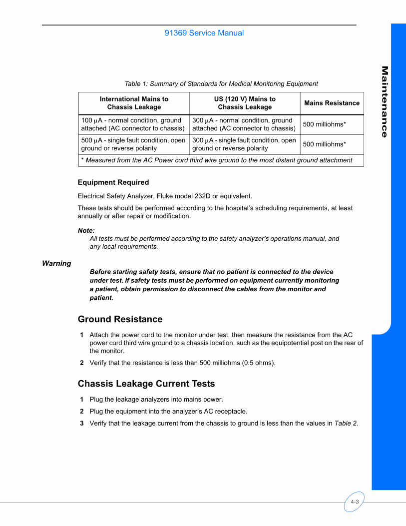
91369 Service ManualM
ain
ten
an
ce
Equipment Required
Electrical Safety Analyzer, Fluke model 232D or equivalent.
These tests should be performed according to the hospital’s scheduling requirements, at least annually or after repair or modification.
Note:All tests must be performed according to the safety analyzer’s operations manual, and any local requirements.
WarningBefore starting safety tests, ensure that no patient is connected to the device under test. If safety tests must be performed on equipment currently monitoring a patient, obtain permission to disconnect the cables from the monitor and patient.
Ground Resistance1 Attach the power cord to the monitor under test, then measure the resistance from the AC
power cord third wire ground to a chassis location, such as the equipotential post on the rear of the monitor.
2 Verify that the resistance is less than 500 milliohms (0.5 ohms).
Chassis Leakage Current Tests1 Plug the leakage analyzers into mains power.
2 Plug the equipment into the analyzer’s AC receptacle.
3 Verify that the leakage current from the chassis to ground is less than the values in Table 2.
Table 1: Summary of Standards for Medical Monitoring Equipment
International Mains toChassis Leakage
US (120 V) Mains toChassis Leakage Mains Resistance
100 µA - normal condition, ground attached (AC connector to chassis)
300 µA - normal condition, ground attached (AC connector to chassis) 500 milliohms*
500 µA - single fault condition, open ground or reverse polarity
300 µA - single fault condition, open ground or reverse polarity 500 milliohms*
* Measured from the AC Power cord third wire ground to the most distant ground attachment
4-3
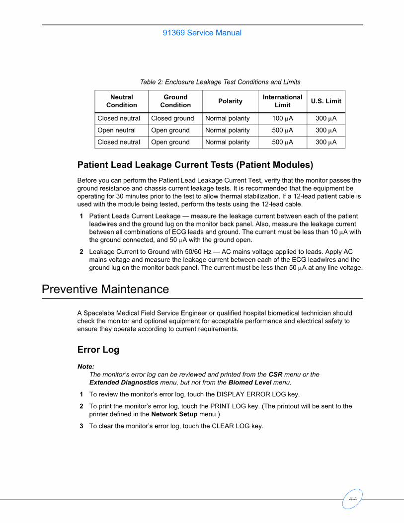
91369 Service Manual
Patient Lead Leakage Current Tests (Patient Modules)Before you can perform the Patient Lead Leakage Current Test, verify that the monitor passes the ground resistance and chassis current leakage tests. It is recommended that the equipment be operating for 30 minutes prior to the test to allow thermal stabilization. If a 12-lead patient cable is used with the module being tested, perform the tests using the 12-lead cable.
1 Patient Leads Current Leakage — measure the leakage current between each of the patient leadwires and the ground lug on the monitor back panel. Also, measure the leakage current between all combinations of ECG leads and ground. The current must be less than 10 µA with the ground connected, and 50 µA with the ground open.
2 Leakage Current to Ground with 50/60 Hz — AC mains voltage applied to leads. Apply AC mains voltage and measure the leakage current between each of the ECG leadwires and the ground lug on the monitor back panel. The current must be less than 50 µA at any line voltage.
Preventive Maintenance
A Spacelabs Medical Field Service Engineer or qualified hospital biomedical technician should check the monitor and optional equipment for acceptable performance and electrical safety to ensure they operate according to current requirements.
Error Log
Note:The monitor’s error log can be reviewed and printed from the CSR menu or the Extended Diagnostics menu, but not from the Biomed Level menu.
1 To review the monitor’s error log, touch the DISPLAY ERROR LOG key.
2 To print the monitor’s error log, touch the PRINT LOG key. (The printout will be sent to the printer defined in the Network Setup menu.)
3 To clear the monitor’s error log, touch the CLEAR LOG key.
Table 2: Enclosure Leakage Test Conditions and Limits
Neutral Condition
Ground Condition Polarity International
Limit U.S. Limit
Closed neutral Closed ground Normal polarity 100 µA 300 µA
Open neutral Open ground Normal polarity 500 µA 300 µA
Closed neutral Open ground Normal polarity 500 µA 300 µA
4-4
91369 Service ManualM
ain
ten
an
ce
Touchscreen CalibrationIn the event the touchscreen becomes difficult to use or a replacement has been installed, you may need to calibrate it. This can be performed using the calibration function in the Biomed menu.
To perform the calibration, attach a mouse (in the event the touchscreen is unusable) and perform the following:
1 Power ON the monitor with the mouse attached and wait for the monitor to pass the self tests.
2 Click (or touch) the MONITOR SETUP key and then click (or touch) the PRIVILEGED ACCESS key.
3 Enter the Biomed password (default is Biomed).
4 Click (touch) MONITOR CALIBRATION.
5 Click (touch) TOUCHSCREEN CALIBRATION and wait for the Reset Monitor dialog box to display. Click (touch) the RESET MONITOR key. The monitor will reset.
6 After 15 to 20 seconds, a lighted box will appear in the upper left corner of the screen. Touch the lighted box for one or two seconds until it disappears.
7 Two more lighted boxes will appear, one at a time, in the upper right and lower right corners. Touch them as they appear.
8 After touching these three corners one at a time as the boxes appear, the touchscreen is calibrated.
Functional Tests
Monitor Self-TestA power-ON self-test is performed each time the monitor is turned ON. • The power ON/OFF switch (refer to Figure 2-1 on page 2-2) illuminates indicating +5 V is
present.• If the monitor is operating on external AC power, the power LED on the front bezel also
illuminates. • If the monitor is operating on AC power and batteries are being charged, the battery A and
battery B status LEDs on the front bezel flash ON and OFF at a constant rate. Once the batteries are fully charged, these LEDs remain ON. If no battery is present, one or both of the battery status LEDs will remain OFF.
Monitor Functional TestsThis procedure verifies operation of the recorder assembly, network connectivity, alarm relay output, and external SDLC connections. It assumes that a 91496 multiparameter module (ECG, RESP, two PRESS channels, and two TEMP channels) is available for testing purposes. In the event that these parameters are not available, similar modules may be substituted.
4-5
91369 Service Manual
Verifying Monitor Functions
Note:To begin the test, make sure no modules are inserted and no Flexports or other SDLC devices are connected.
1 Plug in the monitor and verify that the front bezel power LED is lit. If one or two batteries are installed, verify that the appropriate battery LED(s) are ON solid or flashing.
2 Press the power ON/OFF switch to turn ON the monitor and verify the following sequence of events:a The power ON/OFF switch illuminates. b The embedded alarm light LEDs illuminate briefly. Verify that all LEDs are functional.c The Diagnostic menu displays. (If errors are noted during power-up, contact your
Spacelabs Medical Field Service Engineer.)d If batteries are installed, the fan begins operating within 60 seconds after turning ON the
monitor. The fan will then turn OFF unless the internal temperature requires additional cooling by the fan.
e Monitor keys display along the right side of the screen.
3 Insert the ECG module without a patient cable connected. Verify that the ECG parameter key appears on the screen with ??? and the message LEADS OFF.
4 Connect a patient simulator to the ECG input with a patient cable. Set the simulator to a known rate and verify that the ECG count and the lead being monitored are displayed to the right of the ECG parameter key. Also verify that the ECG waveform appears on the screen.
5 Connect a patient simulator to the invasive pressure inputs.
6 Zero the pressures and verify that the numerics and waveforms are accurate.
Optional Recorder Assembly
If the monitor is configured with the optional recorder assembly, verify that the monitor initiates a recording by touching the RECORD key and then touching one of the flashing parameter keys.
Note:The printed waveform should be free from defects such as gaps, extra lines, etc. If not, notify a Spacelabs Medical Field Service Engineer for servicing, or replace the recorder (refer to Recorder on page 5-17).
Alarm Relay Output
If the monitor is configured to use the alarm relay output to interface to an external alarm device:
1 Plug the cable into the external alarm connector and initiate a high-priority alarm. Verify that the external alarm responds appropriately.
2 If an external alarm light capable of displaying multiple colors is attached, turn the high-priority alarm OFF and generate a medium-priority alarm. Verify that the external alarm responds appropriately.
3 Repeat step 2 for a low-priority alarm.
4-6
91369 Service ManualM
ain
ten
an
ce
An alternate method is to connect the cable and turn the monitor ON and then OFF. Each color of the embedded alarm light will momentarily illuminate. An external alarm light will also briefly illuminate.
Ethernet (Wired)
1 Attach a 10/100BaseT cable from an active network onto the side panel connector.
2 Touch the SPECIAL FUNCTIONS key and verify that other monitors appear in the Remote View menu.
Assembly/Disassembly Procedures
CautionBefore beginning any disassembly procedures, power OFF the monitor, disconnect the AC cord from the AC power receptacle, and remove the batteries.
Note:The external power supply is not designed for disassembly.
Required Tools and Parts • Anti-static mat with wrist strap• #1 and #2 Phillips-head screwdriver• 5/16-inch nut driver• 3/16-inch nut driver
Setup for Disassembly1 Remove the external power supply cable and battery(ies) if present.
2 Remove the patient parameter module.
Installing or Replacing the Optional Recorder Assembly
Note:Unless purchased separately for a monitor already in the field, the recorder option is installed at the factory. Order an upgrade from your local Sales Representative.
The recorder option consists of two components: the recorder module and the recorder CPU PCBA.
The recorder CPU PCBA and recorder module fit into the upper slot on the monitor’s left side (refer to Figure 4-1). The recorder CPU PCBA must be installed first, followed by the recorder module. Refer to Table 1 on page 6-1 for the recorder CPU and recorder assembly part numbers.
4-7
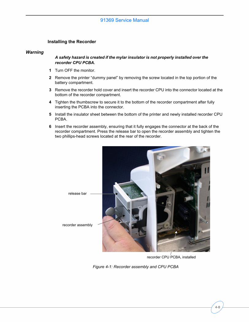
91369 Service Manual
Installing the Recorder
WarningA safety hazard is created if the mylar insulator is not properly installed over the recorder CPU PCBA.
1 Turn OFF the monitor.
2 Remove the printer “dummy panel” by removing the screw located in the top portion of the battery compartment.
3 Remove the recorder hold cover and insert the recorder CPU into the connector located at the bottom of the recorder compartment.
4 Tighten the thumbscrew to secure it to the bottom of the recorder compartment after fully inserting the PCBA into the connector.
5 Install the insulator sheet between the bottom of the printer and newly installed recorder CPU PCBA.
6 Insert the recorder assembly, ensuring that it fully engages the connector at the back of the recorder compartment. Press the release bar to open the recorder assembly and tighten the two phillips-head screws located at the rear of the recorder.
Figure 4-1: Recorder assembly and CPU PCBA
release bar
recorder CPU PCBA, installed
recorder assembly
4-8
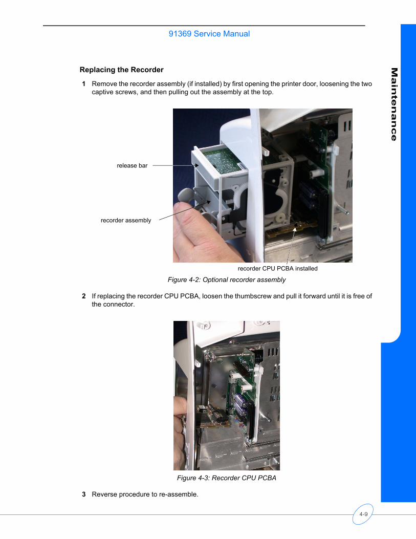
91369 Service ManualM
ain
ten
an
ce
Replacing the Recorder
1 Remove the recorder assembly (if installed) by first opening the printer door, loosening the two captive screws, and then pulling out the assembly at the top.
Figure 4-2: Optional recorder assembly
2 If replacing the recorder CPU PCBA, loosen the thumbscrew and pull it forward until it is free of the connector.
Figure 4-3: Recorder CPU PCBA
3 Reverse procedure to re-assemble.
release bar
recorder assembly
recorder CPU PCBA installed
4-9

91369 Service Manual
Inserting Recorder PaperTwo rolls of thermal recorder paper have been included with the optional recorder assembly. To insert a roll of paper:
1 Press the right side of the release bar at the top of the recorder assembly. The front of the recorder assembly is hinged at the bottom and will drop open, revealing two spoon-shaped arms that hold the paper roll spindle between them.
2 Unroll a short length of paper from the roll, and orient the roll so that the paper feeds from the bottom.
3 Slip the paper roll spindle between the plastic arms, and close the front of the assembly so that the end of the paper roll protrudes out of the recorder assembly just below the release bar.
Removing the Bezel Assembly1 Remove the bezel by removing the five screws along the bottom of the enclosure, and then
stand the monitor upright and remove the four screws along the top of the bezel.
Figure 4-4: Bezel screw locations
four screws along the top of the bezel
five screws along the bottom of the bezel
4-10
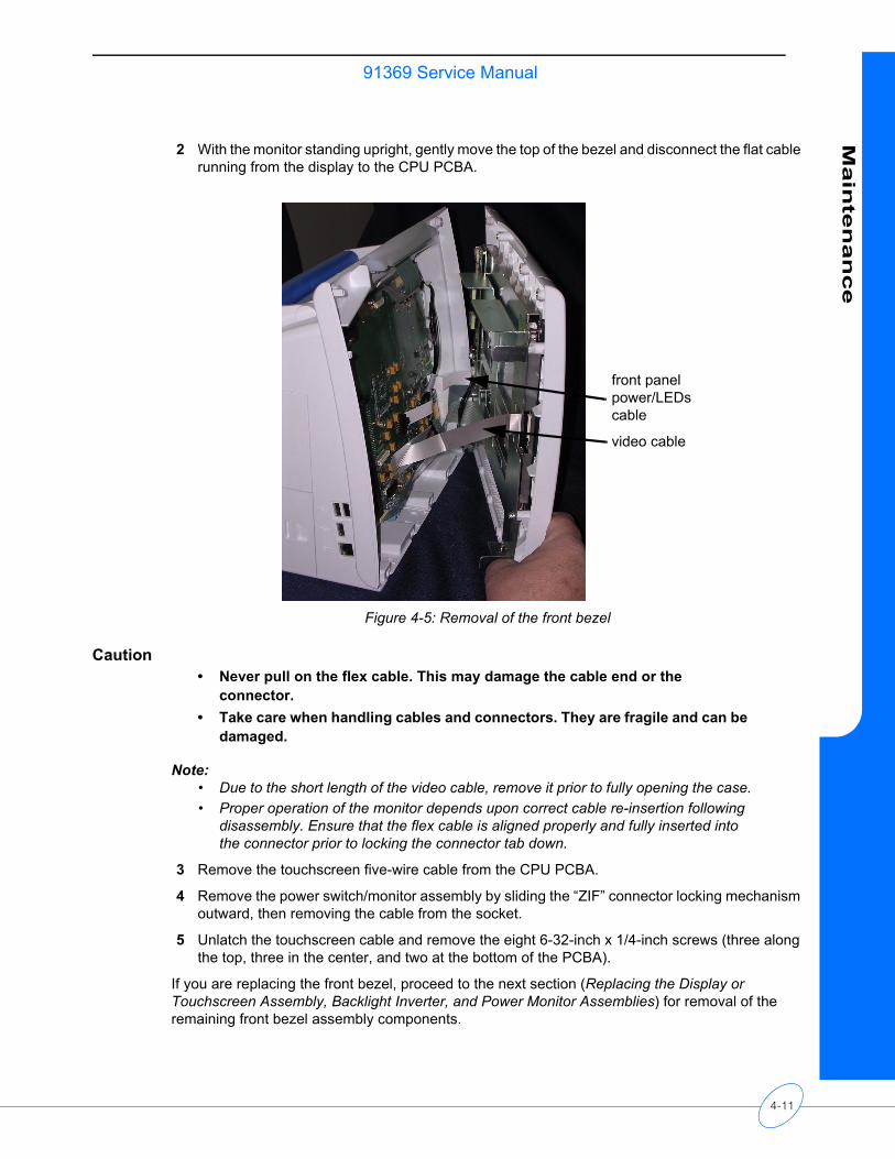
91369 Service ManualM
ain
ten
an
ce
2 With the monitor standing upright, gently move the top of the bezel and disconnect the flat cable running from the display to the CPU PCBA.
Figure 4-5: Removal of the front bezel
Caution• Never pull on the flex cable. This may damage the cable end or the
connector.• Take care when handling cables and connectors. They are fragile and can be
damaged.
Note:• Due to the short length of the video cable, remove it prior to fully opening the case.• Proper operation of the monitor depends upon correct cable re-insertion following
disassembly. Ensure that the flex cable is aligned properly and fully inserted into the connector prior to locking the connector tab down.
3 Remove the touchscreen five-wire cable from the CPU PCBA.
4 Remove the power switch/monitor assembly by sliding the “ZIF” connector locking mechanism outward, then removing the cable from the socket.
5 Unlatch the touchscreen cable and remove the eight 6-32-inch x 1/4-inch screws (three along the top, three in the center, and two at the bottom of the PCBA).
If you are replacing the front bezel, proceed to the next section (Replacing the Display or Touchscreen Assembly, Backlight Inverter, and Power Monitor Assemblies) for removal of the remaining front bezel assembly components.
front panel power/LEDs cable
video cable
4-11
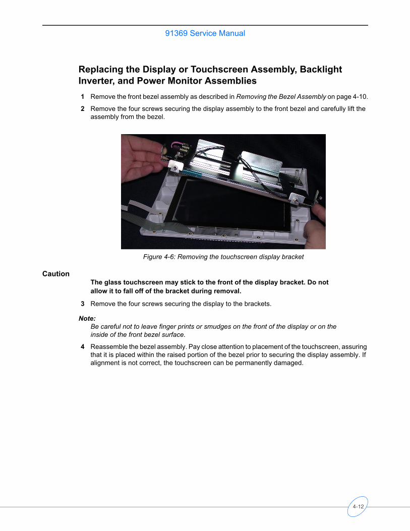
91369 Service Manual
Replacing the Display or Touchscreen Assembly, Backlight Inverter, and Power Monitor Assemblies1 Remove the front bezel assembly as described in Removing the Bezel Assembly on page 4-10.
2 Remove the four screws securing the display assembly to the front bezel and carefully lift the assembly from the bezel.
Figure 4-6: Removing the touchscreen display bracket
CautionThe glass touchscreen may stick to the front of the display bracket. Do not allow it to fall off of the bracket during removal.
3 Remove the four screws securing the display to the brackets.
Note:Be careful not to leave finger prints or smudges on the front of the display or on the inside of the front bezel surface.
4 Reassemble the bezel assembly. Pay close attention to placement of the touchscreen, assuring that it is placed within the raised portion of the bezel prior to securing the display assembly. If alignment is not correct, the touchscreen can be permanently damaged.
4-12
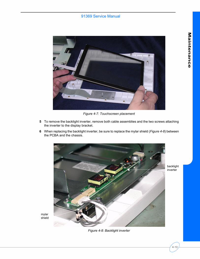
91369 Service ManualM
ain
ten
an
ce
Figure 4-7: Touchscreen placement
5 To remove the backlight inverter, remove both cable assemblies and the two screws attaching the inverter to the display bracket.
6 When replacing the backlight inverter, be sure to replace the mylar shield (Figure 4-8) between the PCBA and the chassis.
Figure 4-8: Backlight inverter
backlight inverter
mylar shield
4-13
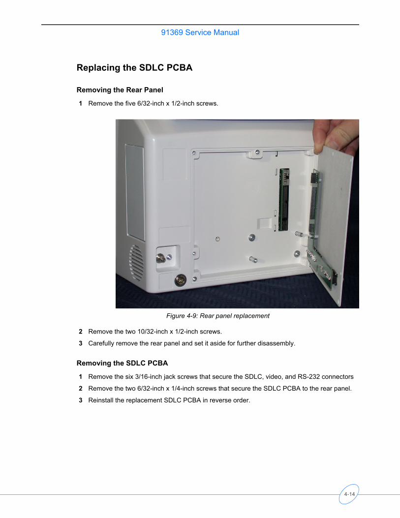
91369 Service Manual
Replacing the SDLC PCBA
Removing the Rear Panel
1 Remove the five 6/32-inch x 1/2-inch screws.
Figure 4-9: Rear panel replacement
2 Remove the two 10/32-inch x 1/2-inch screws.
3 Carefully remove the rear panel and set it aside for further disassembly.
Removing the SDLC PCBA
1 Remove the six 3/16-inch jack screws that secure the SDLC, video, and RS-232 connectors
2 Remove the two 6/32-inch x 1/4-inch screws that secure the SDLC PCBA to the rear panel.
3 Reinstall the replacement SDLC PCBA in reverse order.
4-14
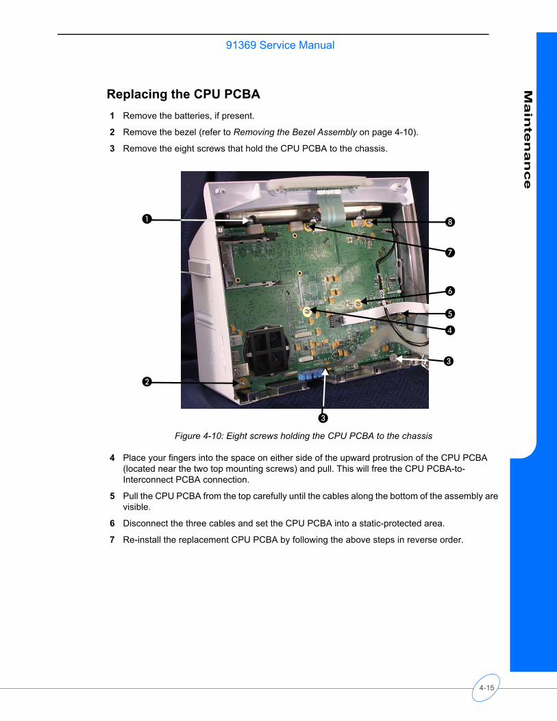
91369 Service ManualM
ain
ten
an
ce
Replacing the CPU PCBA1 Remove the batteries, if present.
2 Remove the bezel (refer to Removing the Bezel Assembly on page 4-10).
3 Remove the eight screws that hold the CPU PCBA to the chassis.
Figure 4-10: Eight screws holding the CPU PCBA to the chassis
4 Place your fingers into the space on either side of the upward protrusion of the CPU PCBA (located near the two top mounting screws) and pull. This will free the CPU PCBA-to-Interconnect PCBA connection.
5 Pull the CPU PCBA from the top carefully until the cables along the bottom of the assembly are visible.
6 Disconnect the three cables and set the CPU PCBA into a static-protected area.
7 Re-install the replacement CPU PCBA by following the above steps in reverse order.
�
�
�
�
�
�
�
4-15
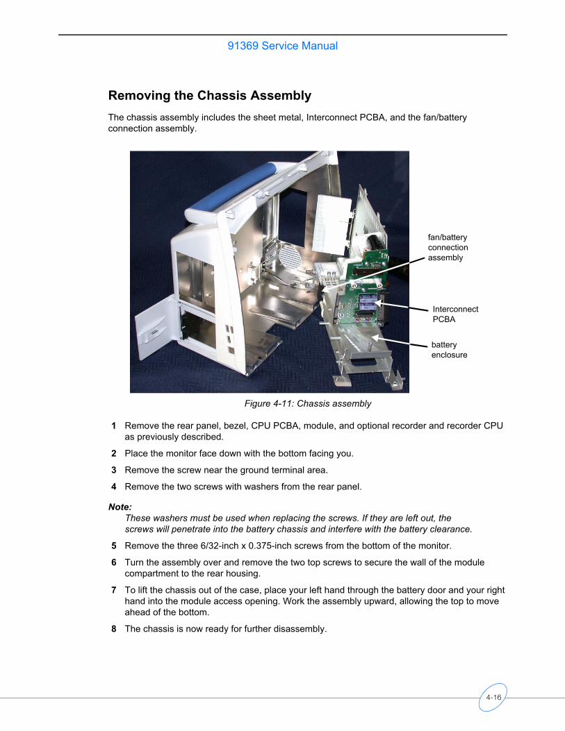
91369 Service Manual
Removing the Chassis AssemblyThe chassis assembly includes the sheet metal, Interconnect PCBA, and the fan/battery connection assembly.
Figure 4-11: Chassis assembly
1 Remove the rear panel, bezel, CPU PCBA, module, and optional recorder and recorder CPU as previously described.
2 Place the monitor face down with the bottom facing you.
3 Remove the screw near the ground terminal area.
4 Remove the two screws with washers from the rear panel.
Note:These washers must be used when replacing the screws. If they are left out, the screws will penetrate into the battery chassis and interfere with the battery clearance.
5 Remove the three 6/32-inch x 0.375-inch screws from the bottom of the monitor.
6 Turn the assembly over and remove the two top screws to secure the wall of the module compartment to the rear housing.
7 To lift the chassis out of the case, place your left hand through the battery door and your right hand into the module access opening. Work the assembly upward, allowing the top to move ahead of the bottom.
8 The chassis is now ready for further disassembly.
battery enclosure
Interconnect PCBA
fan/battery connection assembly
4-16
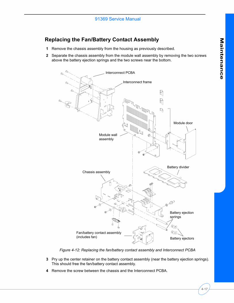
91369 Service ManualM
ain
ten
an
ce
Replacing the Fan/Battery Contact Assembly1 Remove the chassis assembly from the housing as previously described.
2 Separate the chassis assembly from the module wall assembly by removing the two screws above the battery ejection springs and the two screws near the bottom.
Figure 4-12: Replacing the fan/battery contact assembly and Interconnect PCBA
3 Pry up the center retainer on the battery contact assembly (near the battery ejection springs). This should free the fan/battery contact assembly.
4 Remove the screw between the chassis and the Interconnect PCBA.
Interconnect PCBA
Interconnect frame
Module wall assembly
Module door
Battery divider
Battery ejection springs
Battery ejectors
Chassis assembly
Fan/battery contact assembly(includes fan)
4-17
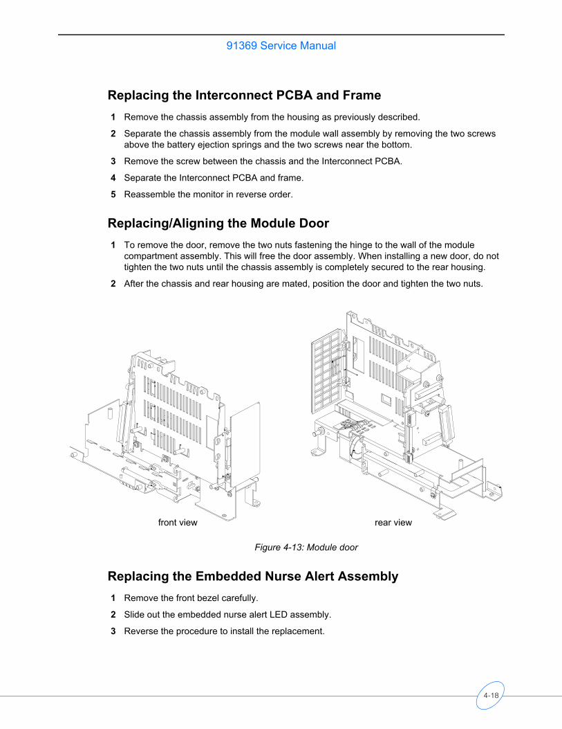
91369 Service Manual
Replacing the Interconnect PCBA and Frame1 Remove the chassis assembly from the housing as previously described.
2 Separate the chassis assembly from the module wall assembly by removing the two screws above the battery ejection springs and the two screws near the bottom.
3 Remove the screw between the chassis and the Interconnect PCBA.
4 Separate the Interconnect PCBA and frame.
5 Reassemble the monitor in reverse order.
Replacing/Aligning the Module Door1 To remove the door, remove the two nuts fastening the hinge to the wall of the module
compartment assembly. This will free the door assembly. When installing a new door, do not tighten the two nuts until the chassis assembly is completely secured to the rear housing.
2 After the chassis and rear housing are mated, position the door and tighten the two nuts.
Figure 4-13: Module door
Replacing the Embedded Nurse Alert Assembly1 Remove the front bezel carefully.
2 Slide out the embedded nurse alert LED assembly.
3 Reverse the procedure to install the replacement.
rear viewfront view
4-18
91369 Service ManualM
ain
ten
an
ce
Cleaning
Clean the case by washing it with mild soap and water or use Plast-N-Glas cleaner. Use TF solvent for cleaning the electronic connectors and contacts as necessary.
Note:Avoid directly spraying liquids into the recorder openings.
Caution• Do not autoclave.• Never use solvents, acetone, abrasive cleaning agents, or abrasive cleaning
pads.• Use only approved cleaning agents including 70% alcohol, soap and water,
green soap, or 10% bleach solution.
4-19

Troubleshooting
Contents
Overview . . . . . . . . . . . . . . . . . . . . . . . . . . . . . . . . . . . . . . . . . . . . . . . . . . . . . . . . . . . 1System Startup . . . . . . . . . . . . . . . . . . . . . . . . . . . . . . . . . . . . . . . . . . . . . . . . . . . . . . 2Boot Menu . . . . . . . . . . . . . . . . . . . . . . . . . . . . . . . . . . . . . . . . . . . . . . . . . . . . . . . . . . 3Power-ON Diagnostics . . . . . . . . . . . . . . . . . . . . . . . . . . . . . . . . . . . . . . . . . . . . . . . . 5Extended Diagnostics . . . . . . . . . . . . . . . . . . . . . . . . . . . . . . . . . . . . . . . . . . . . . . . . . 6Diagnostic Menus . . . . . . . . . . . . . . . . . . . . . . . . . . . . . . . . . . . . . . . . . . . . . . . . . . . . 7Error Log . . . . . . . . . . . . . . . . . . . . . . . . . . . . . . . . . . . . . . . . . . . . . . . . . . . . . . . . . . 10Diagnostics Failure Messages and Error Codes . . . . . . . . . . . . . . . . . . . . . . . . . . . . 11System Troubleshooting . . . . . . . . . . . . . . . . . . . . . . . . . . . . . . . . . . . . . . . . . . . . . . 13Overview
The first several sections describe the available diagnostics features and how to use them. This is followed by a section which lists diagnostics failure messages and the suggested corrective actions. The last section gives specific troubleshooting steps which can be used to isolate failures.
The troubleshooting procedures in this chapter isolate equipment problems to a Field Replaceable Unit (FRU).
The following items are field-replaceable:• PCBA, Connector• PCBA, Interconnect• PCBA, CPU• All sheet metal and plastic parts• External DC power supply• LCD display• 5-wire resistive touchscreen• Internal alarm LED assembly• Power indicator flexboard• Backlight inverter board
CautionObserve precautions for handling electrostatic-sensitive devices!
Note:• Never touch electrostatic-sensitive electronic components without following proper
anti-static procedures, including the use of an ESD wrist band and mat. An electrostatic discharge from your fingers can permanently damage electronic components and cause latent failures.
• All static-sensitive electronic components are packaged in static-shielding bags. Retain the bag for repackaging the component should you need to store it or return it to Spacelabs Medical for any reason.
5-1
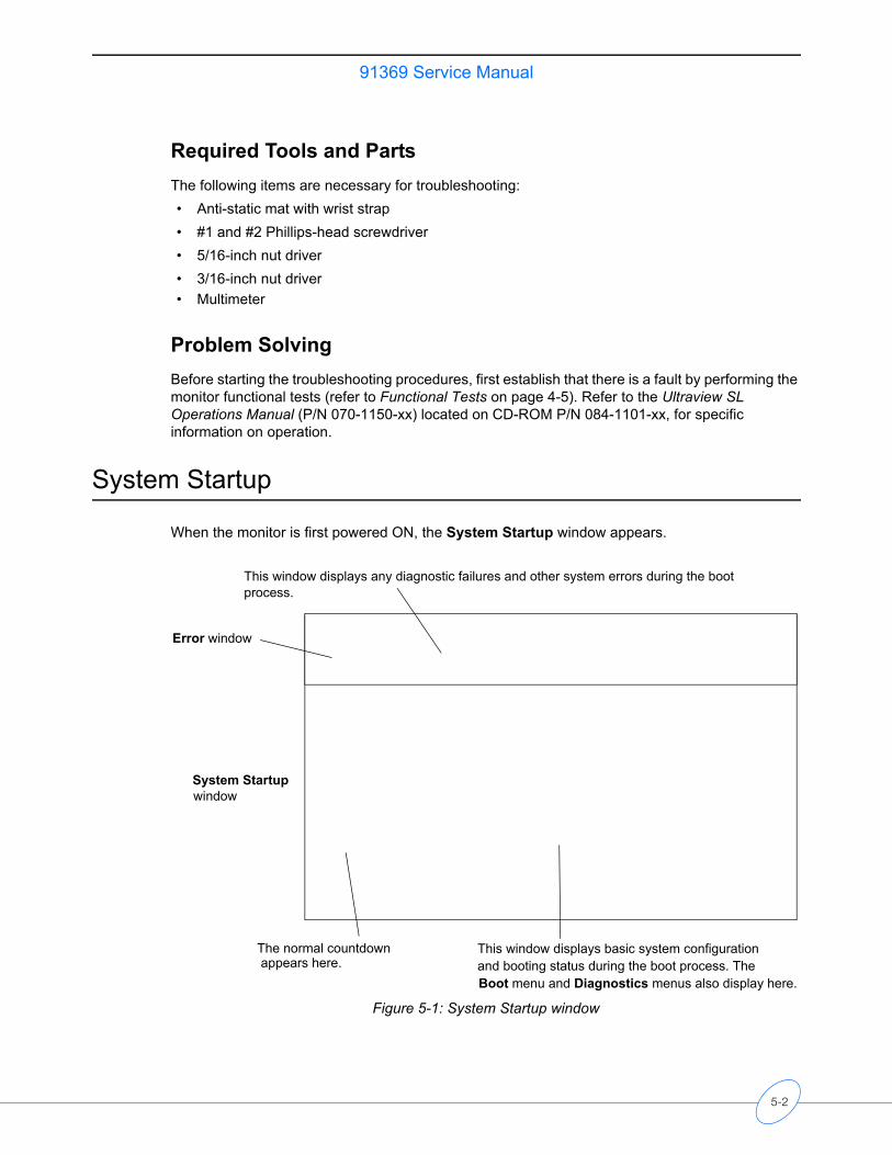
91369 Service Manual
Required Tools and PartsThe following items are necessary for troubleshooting:• Anti-static mat with wrist strap• #1 and #2 Phillips-head screwdriver• 5/16-inch nut driver• 3/16-inch nut driver• Multimeter
Problem SolvingBefore starting the troubleshooting procedures, first establish that there is a fault by performing the monitor functional tests (refer to Functional Tests on page 4-5). Refer to the Ultraview SL Operations Manual (P/N 070-1150-xx) located on CD-ROM P/N 084-1101-xx, for specific information on operation.
System Startup
When the monitor is first powered ON, the System Startup window appears.
Figure 5-1: System Startup window
This window displays any diagnostic failures and other system errors during the bootprocess.
Error window
System Startupwindow
The normal countdown This window displays basic system configurationand booting status during the boot process. The Boot menu and Diagnostics menus also display here.
appears here.
5-2
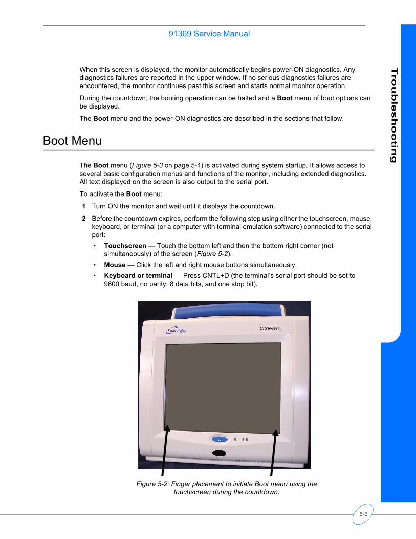
91369 Service ManualTro
ub
lesh
oo
ting
When this screen is displayed, the monitor automatically begins power-ON diagnostics. Any diagnostics failures are reported in the upper window. If no serious diagnostics failures are encountered, the monitor continues past this screen and starts normal monitor operation.
During the countdown, the booting operation can be halted and a Boot menu of boot options can be displayed.
The Boot menu and the power-ON diagnostics are described in the sections that follow.
Boot Menu
The Boot menu (Figure 5-3 on page 5-4) is activated during system startup. It allows access to several basic configuration menus and functions of the monitor, including extended diagnostics. All text displayed on the screen is also output to the serial port.
To activate the Boot menu:
1 Turn ON the monitor and wait until it displays the countdown.
2 Before the countdown expires, perform the following step using either the touchscreen, mouse, keyboard, or terminal (or a computer with terminal emulation software) connected to the serial port:• Touchscreen — Touch the bottom left and then the bottom right corner (not
simultaneously) of the screen (Figure 5-2).• Mouse — Click the left and right mouse buttons simultaneously.• Keyboard or terminal — Press CNTL+D (the terminal’s serial port should be set to
9600 baud, no parity, 8 data bits, and one stop bit).
Figure 5-2: Finger placement to initiate Boot menu using the touchscreen during the countdown.
5-3
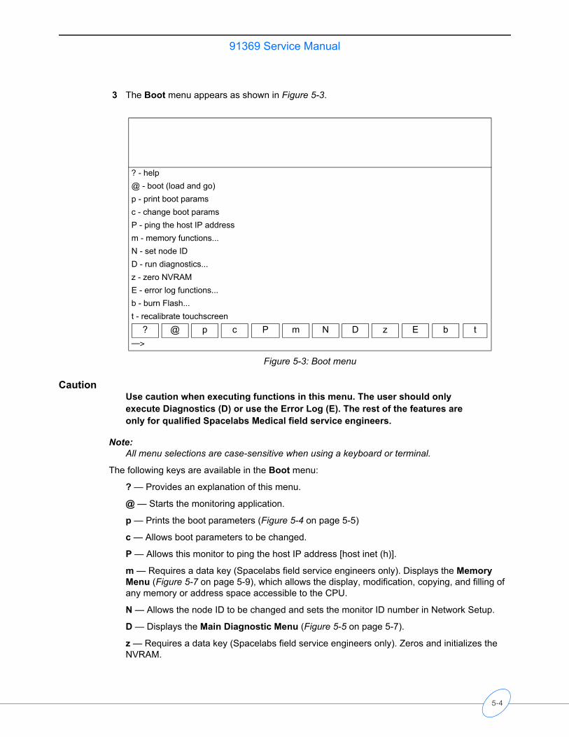
91369 Service Manual
3 The Boot menu appears as shown in Figure 5-3.
Figure 5-3: Boot menu
CautionUse caution when executing functions in this menu. The user should only execute Diagnostics (D) or use the Error Log (E). The rest of the features are only for qualified Spacelabs Medical field service engineers.
Note:All menu selections are case-sensitive when using a keyboard or terminal.
The following keys are available in the Boot menu:
? — Provides an explanation of this menu.
@ — Starts the monitoring application.
p — Prints the boot parameters (Figure 5-4 on page 5-5)
c — Allows boot parameters to be changed.
P — Allows this monitor to ping the host IP address [host inet (h)].
m — Requires a data key (Spacelabs field service engineers only). Displays the Memory Menu (Figure 5-7 on page 5-9), which allows the display, modification, copying, and filling of any memory or address space accessible to the CPU.
N — Allows the node ID to be changed and sets the monitor ID number in Network Setup.
D — Displays the Main Diagnostic Menu (Figure 5-5 on page 5-7).
z — Requires a data key (Spacelabs field service engineers only). Zeros and initializes the NVRAM.
? - help@ - boot (load and go)p - print boot paramsc - change boot paramsP - ping the host IP addressm - memory functions...N - set node IDD - run diagnostics...z - zero NVRAME - error log functions...b - burn Flash...t - recalibrate touchscreen
? @ p c P m N D z E b t—>
5-4
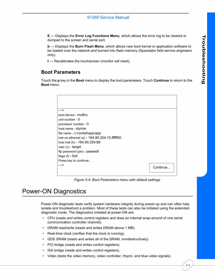
91369 Service ManualTro
ub
lesh
oo
ting
E — Displays the Error Log Functions Menu, which allows the error log to be cleared or dumped to the screen and serial port.
b — Displays the Burn Flash Menu, which allows new boot kernel or application software to be loaded over the network and burned into flash memory (Spacelabs field service engineers only).
t — Recalibrates the touchscreen (monitor will reset).
Boot ParametersTouch the p key in the Boot menu to display the boot parameters. Touch Continue to return to the Boot menu.
Figure 5-4: Boot Parameters menu with default settings
Power-ON Diagnostics
Power-ON diagnostic tests verify system hardware integrity during power-up and can often help isolate and troubleshoot a problem. Most of these tests can also be initiated using the extended diagnostic mode. The diagnostics initiated at power-ON are:• CPU (reads and writes control registers and does an internal wrap-around of one serial
communication controller channel).• DRAM read/write (reads and writes DRAM above 1 MB).• Real-time clock (verifies that the clock is running).• GDS SRAM (reads and writes all of the SRAM, nondestructively).• PCI bridge (reads and writes control registers).• ISA bridge (reads and writes control registers).• Video (tests the video memory, video controller, Hsync, and blue video signals).
—>boot device - motfccunit number - 0processor number - 0host name - stymiefile name - c:\rocket\app\appinet on ethernet (e) - 164.90.254.10.ffffff00host inet (h) - 164.90.254:66user (u) - targetftp password (pw) - passwdlflags (f) - 0x0Press key to continue...—> Continue...
5-5
91369 Service Manual
• Ethernet (reads and writes control registers).• Flash checksum (checksums all flash memory).• Touchscreen (tests the touchscreen controller).• Audio (reads and writes control registers in the codec).
Power-ON diagnostic failures are reported in the upper portion of the System Startup screen. Refer to System Startup on page 5-2 for additional information.
Any error that occurs during one of these tests is logged in the non-volatile configuration memory. Refer to Error Log on page 5-10 to retrieve the log.
Extended Diagnostics
Extended diagnostic tests, like the power-ON diagnostics, can be used to troubleshoot and isolate many system failures. The types of tests and features available in the extended diagnostics are:• Power-ON diagnostics.• Interactive tests and read/write memory tests that are not appropriate during power-ON
diagnostics.• Touchscreen calibration and data dump utilities.• System data dump and system reset utilities.
The diagnostic menus allow most of these tests to be run individually or all at once. If Loop mode is activated, a test(s) can be executed in a continuous loop. If Halt On Error mode is activated, the looping stops when a diagnostic failure is detected. To avoid false failures, do not use the touchscreen, mouse, or keyboard while the diagnostic tests are executing.
Extended diagnostics failures are reported in the upper left corner of the System Startup screen. Refer to System Startup on page 5-2 for more information.
Any error that occurs during one of these tests is logged in the non-volatile memory. Refer to Error Log on page 5-10 to retrieve the log.
For detailed information on extended diagnostics and how to run them, refer to Diagnostic Menus below.
5-6
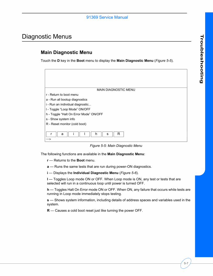
91369 Service ManualTro
ub
lesh
oo
ting
Diagnostic Menus
Main Diagnostic MenuTouch the D key in the Boot menu to display the Main Diagnostic Menu (Figure 5-5).
Figure 5-5: Main Diagnostic Menu
The following functions are available in the Main Diagnostic Menu:
r — Returns to the Boot menu.
a — Runs the same tests that are run during power-ON diagnostics.
i — Displays the Individual Diagnostic Menu (Figure 5-6).
l — Toggles Loop mode ON or OFF. When Loop mode is ON, any test or tests that are selected will run in a continuous loop until power is turned OFF.
h — Toggles Halt On Error mode ON or OFF. When ON, any failure that occurs while tests are running in Loop mode immediately stops testing.
s — Shows system information, including details of address spaces and variables used in the system.
R — Causes a cold boot reset just like turning the power OFF.
MAIN DIAGNOSTIC MENUr - Return to boot menua - Run all bootup diagnosticsi - Run an individual diagnostic...l - Toggle “Loop Mode” ON/OFFh - Toggle “Halt On Error Mode” ON/OFFs - Show system infoR - Reset monitor (cold boot)
r a i l h s R—>
5-7
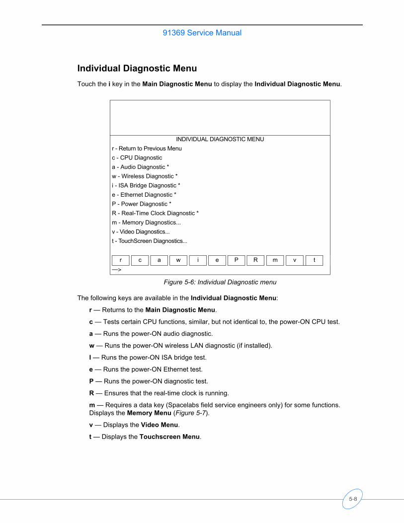
91369 Service Manual
Individual Diagnostic MenuTouch the i key in the Main Diagnostic Menu to display the Individual Diagnostic Menu.
Figure 5-6: Individual Diagnostic menu
The following keys are available in the Individual Diagnostic Menu:
r — Returns to the Main Diagnostic Menu.
c — Tests certain CPU functions, similar, but not identical to, the power-ON CPU test.
a — Runs the power-ON audio diagnostic.
w — Runs the power-ON wireless LAN diagnostic (if installed).
I — Runs the power-ON ISA bridge test.
e — Runs the power-ON Ethernet test.
P — Runs the power-ON diagnostic test.
R — Ensures that the real-time clock is running.
m — Requires a data key (Spacelabs field service engineers only) for some functions. Displays the Memory Menu (Figure 5-7).
v — Displays the Video Menu.
t — Displays the Touchscreen Menu.
INDIVIDUAL DIAGNOSTIC MENUr - Return to Previous Menuc - CPU Diagnostica - Audio Diagnostic *w - Wireless Diagnostic *i - ISA Bridge Diagnostic *e - Ethernet Diagnostic *P - Power Diagnostic *R - Real-Time Clock Diagnostic *m - Memory Diagnostics...v - Video Diagnostics...t - TouchScreen Diagnostics...
r c a w i e P R m v t—>
5-8
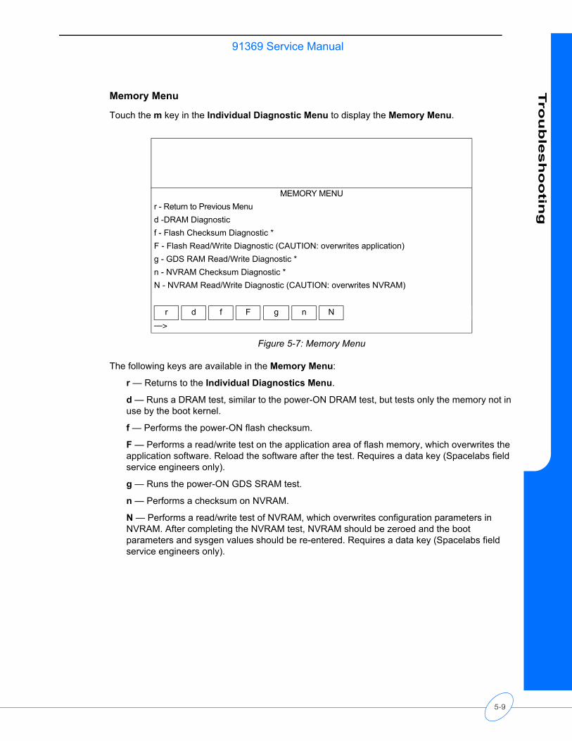
91369 Service ManualTro
ub
lesh
oo
ting
Memory Menu
Touch the m key in the Individual Diagnostic Menu to display the Memory Menu.
Figure 5-7: Memory Menu
The following keys are available in the Memory Menu:
r — Returns to the Individual Diagnostics Menu.
d — Runs a DRAM test, similar to the power-ON DRAM test, but tests only the memory not in use by the boot kernel.
f — Performs the power-ON flash checksum.
F — Performs a read/write test on the application area of flash memory, which overwrites the application software. Reload the software after the test. Requires a data key (Spacelabs field service engineers only).
g — Runs the power-ON GDS SRAM test.
n — Performs a checksum on NVRAM.
N — Performs a read/write test of NVRAM, which overwrites configuration parameters in NVRAM. After completing the NVRAM test, NVRAM should be zeroed and the boot parameters and sysgen values should be re-entered. Requires a data key (Spacelabs field service engineers only).
MEMORY MENUr - Return to Previous Menud -DRAM Diagnosticf - Flash Checksum Diagnostic *F - Flash Read/Write Diagnostic (CAUTION: overwrites application)g - GDS RAM Read/Write Diagnostic *n - NVRAM Checksum Diagnostic *N - NVRAM Read/Write Diagnostic (CAUTION: overwrites NVRAM)
r d f F g n N—>
5-9
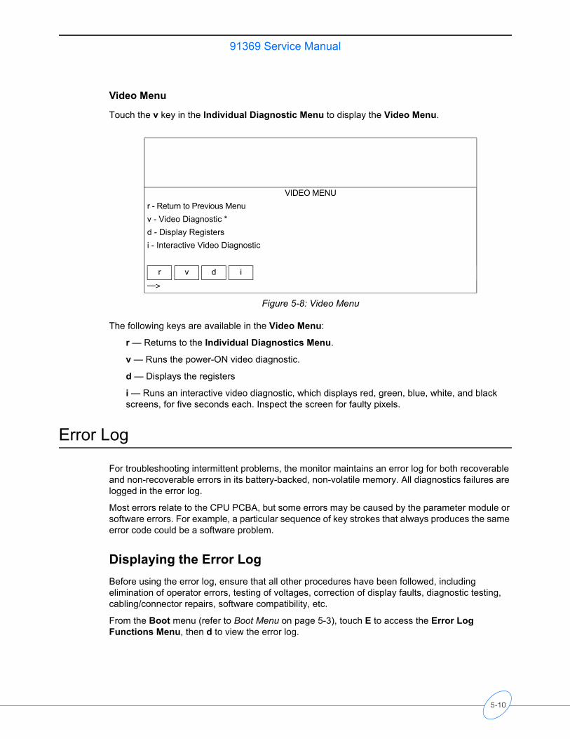
91369 Service Manual
Video Menu
Touch the v key in the Individual Diagnostic Menu to display the Video Menu.
Figure 5-8: Video Menu
The following keys are available in the Video Menu:
r — Returns to the Individual Diagnostics Menu.
v — Runs the power-ON video diagnostic.
d — Displays the registers
i — Runs an interactive video diagnostic, which displays red, green, blue, white, and black screens, for five seconds each. Inspect the screen for faulty pixels.
Error Log
For troubleshooting intermittent problems, the monitor maintains an error log for both recoverable and non-recoverable errors in its battery-backed, non-volatile memory. All diagnostics failures are logged in the error log.
Most errors relate to the CPU PCBA, but some errors may be caused by the parameter module or software errors. For example, a particular sequence of key strokes that always produces the same error code could be a software problem.
Displaying the Error LogBefore using the error log, ensure that all other procedures have been followed, including elimination of operator errors, testing of voltages, correction of display faults, diagnostic testing, cabling/connector repairs, software compatibility, etc.
From the Boot menu (refer to Boot Menu on page 5-3), touch E to access the Error Log Functions Menu, then d to view the error log.
VIDEO MENUr - Return to Previous Menuv - Video Diagnostic *d - Display Registersi - Interactive Video Diagnostic
r v d i—>
5-10
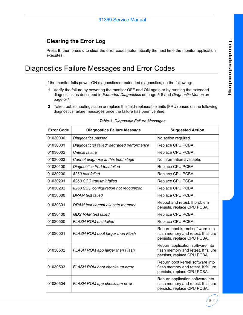
91369 Service ManualTro
ub
lesh
oo
ting
Clearing the Error LogPress E, then press c to clear the error codes automatically the next time the monitor application executes.
Diagnostics Failure Messages and Error Codes
If the monitor fails power-ON diagnostics or extended diagnostics, do the following:
1 Verify the failure by powering the monitor OFF and ON again or by running the extended diagnostics as described in Extended Diagnostics on page 5-6 and Diagnostic Menus on page 5-7.
2 Take troubleshooting action or replace the field-replaceable units (FRU) based on the following diagnostics failure messages once the failure has been verified.
Table 1: Diagnostic Failure Messages
Error Code Diagnostics Failure Message Suggested Action
01030000 Diagnostics passed No action required.
01030001 Diagnostic(s) failed; degraded performance Replace CPU PCBA.
01030002 Critical failure Replace CPU PCBA.
01030003 Cannot diagnose at this boot stage No information available.
01030100 Diagnostics Port test failed Replace CPU PCBA.
01030200 8260 test failed Replace CPU PCBA.
01030201 8260 SCC transmit failed Replace CPU PCBA.
01030202 8260 SCC configuration not recognized Replace CPU PCBA.
01030300 DRAM test failed Replace CPU PCBA.
01030301 DRAM test cannot allocate memory Reboot and retest. If problem persists, replace CPU PCBA.
01030400 GDS RAM test failed Replace CPU PCBA.
01030500 FLASH ROM test failed Replace CPU PCBA.
01030501 FLASH ROM boot larger than FlashReburn boot kernel software into flash memory and retest. If failure persists, replace CPU PCBA.
01030502 FLASH ROM app larger than FlashReburn application software into flash memory and retest. If failure persists, replace CPU PCBA.
01030503 FLASH ROM boot checksum errorReburn boot kernel software into flash memory and retest. If failure persists, replace CPU PCBA.
01030504 FLASH ROM app checksum errorReburn application software into flash memory and retest. If failure persists, replace CPU PCBA.
5-11
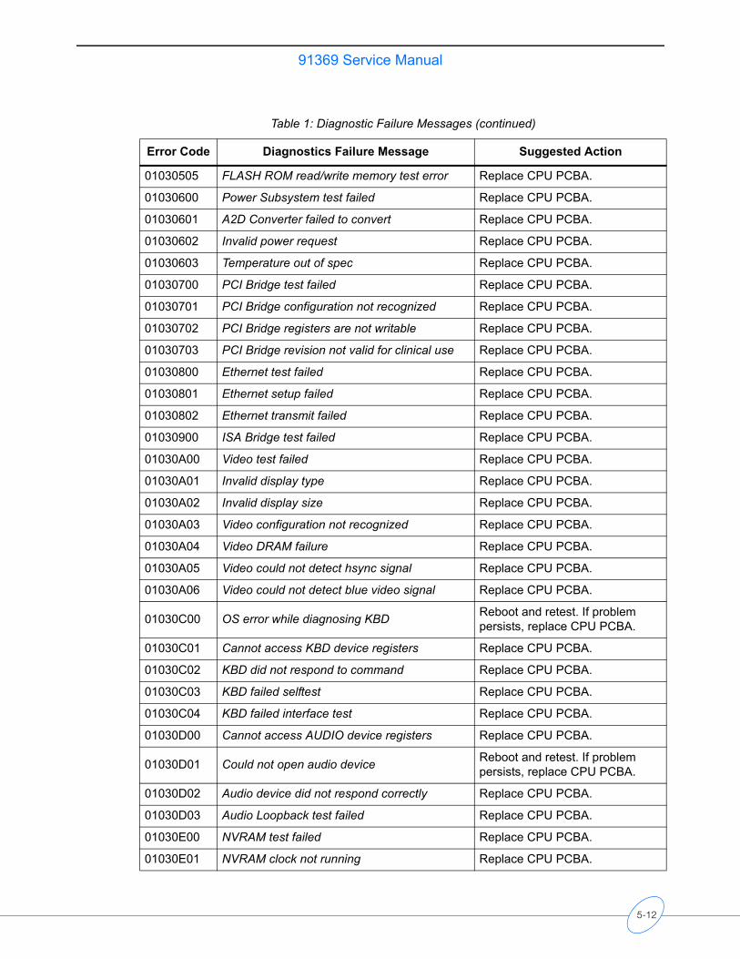
91369 Service Manual
01030505 FLASH ROM read/write memory test error Replace CPU PCBA.
01030600 Power Subsystem test failed Replace CPU PCBA.
01030601 A2D Converter failed to convert Replace CPU PCBA.
01030602 Invalid power request Replace CPU PCBA.
01030603 Temperature out of spec Replace CPU PCBA.
01030700 PCI Bridge test failed Replace CPU PCBA.
01030701 PCI Bridge configuration not recognized Replace CPU PCBA.
01030702 PCI Bridge registers are not writable Replace CPU PCBA.
01030703 PCI Bridge revision not valid for clinical use Replace CPU PCBA.
01030800 Ethernet test failed Replace CPU PCBA.
01030801 Ethernet setup failed Replace CPU PCBA.
01030802 Ethernet transmit failed Replace CPU PCBA.
01030900 ISA Bridge test failed Replace CPU PCBA.
01030A00 Video test failed Replace CPU PCBA.
01030A01 Invalid display type Replace CPU PCBA.
01030A02 Invalid display size Replace CPU PCBA.
01030A03 Video configuration not recognized Replace CPU PCBA.
01030A04 Video DRAM failure Replace CPU PCBA.
01030A05 Video could not detect hsync signal Replace CPU PCBA.
01030A06 Video could not detect blue video signal Replace CPU PCBA.
01030C00 OS error while diagnosing KBD Reboot and retest. If problem persists, replace CPU PCBA.
01030C01 Cannot access KBD device registers Replace CPU PCBA.
01030C02 KBD did not respond to command Replace CPU PCBA.
01030C03 KBD failed selftest Replace CPU PCBA.
01030C04 KBD failed interface test Replace CPU PCBA.
01030D00 Cannot access AUDIO device registers Replace CPU PCBA.
01030D01 Could not open audio device Reboot and retest. If problem persists, replace CPU PCBA.
01030D02 Audio device did not respond correctly Replace CPU PCBA.
01030D03 Audio Loopback test failed Replace CPU PCBA.
01030E00 NVRAM test failed Replace CPU PCBA.
01030E01 NVRAM clock not running Replace CPU PCBA.
Table 1: Diagnostic Failure Messages (continued)
Error Code Diagnostics Failure Message Suggested Action
5-12
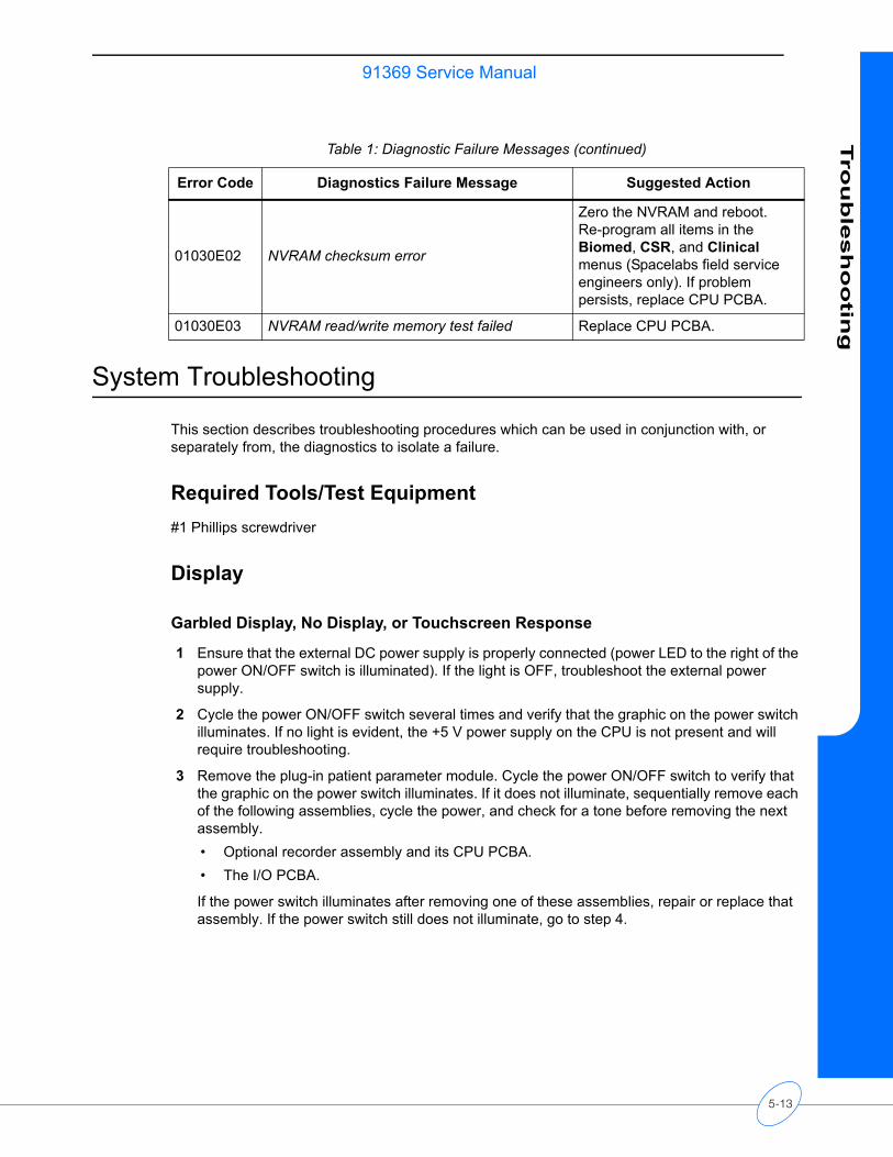
91369 Service ManualTro
ub
lesh
oo
ting
System Troubleshooting
This section describes troubleshooting procedures which can be used in conjunction with, or separately from, the diagnostics to isolate a failure.
Required Tools/Test Equipment#1 Phillips screwdriver
Display
Garbled Display, No Display, or Touchscreen Response
1 Ensure that the external DC power supply is properly connected (power LED to the right of the power ON/OFF switch is illuminated). If the light is OFF, troubleshoot the external power supply.
2 Cycle the power ON/OFF switch several times and verify that the graphic on the power switch illuminates. If no light is evident, the +5 V power supply on the CPU is not present and will require troubleshooting.
3 Remove the plug-in patient parameter module. Cycle the power ON/OFF switch to verify that the graphic on the power switch illuminates. If it does not illuminate, sequentially remove each of the following assemblies, cycle the power, and check for a tone before removing the next assembly. • Optional recorder assembly and its CPU PCBA.• The I/O PCBA.
If the power switch illuminates after removing one of these assemblies, repair or replace that assembly. If the power switch still does not illuminate, go to step 4.
01030E02 NVRAM checksum error
Zero the NVRAM and reboot. Re-program all items in the Biomed, CSR, and Clinical menus (Spacelabs field service engineers only). If problem persists, replace CPU PCBA.
01030E03 NVRAM read/write memory test failed Replace CPU PCBA.
Table 1: Diagnostic Failure Messages (continued)
Error Code Diagnostics Failure Message Suggested Action
5-13

91369 Service Manual
Caution• Partial disassembly may be required for troubleshooting. Ensure that the
external power supply and rechargeable battery(ies) are disconnected. When disassembling the monitor, use a nonconductive, anti-static material to insulate the CPU PCBA from the front bezel assembly (a piece of cardboard will suffice).
• The ends of the cables that connect the front bezel of the CPU PCBA to the display must be handled with care. When disconnecting this cable, the latch should be gently lifted using finger pressure. A broken latch may still lock the cable into the connector, but it will not provide guidance for centering the cable into the connector.
4 Remove the front bezel assembly. Once the CPU PCBA is accessible, check the cable connections between it and the display and verify that the backlight is visible.
If the entire display is garbled or distorted:• Check the cables and connectors interfacing the display to the CPU PCBA. A patient
parameter module may need to be installed to view the top half of the display. If the connections are okay, replace first the CPU PCBA, then the display screen.
CautionDo not attempt to troubleshoot the display backlight electronics. There are very HIGH AC voltages in this area. Only qualified Spacelabs Medical field service engineers should attempt to troubleshoot this section.
Monitor Fails Power-ON Diagnostics
Troubleshooting Method 1: Using the Touchscreen or Mouse
1 Display the Main Diagnostic Menu.
This menu is activated using the touchscreen or mouse. Press the left and right mouse buttons simultaneously, or touch the lower left and then the lower right corners, one at a time, during the “4, 3, 2, 1” countdown.
2 Click (or touch) the test parameter key that retests the previously indicated failure.
Upon verification of the failure, a message provided by the monitor directs you to the field-replaceable unit that failed.
Troubleshooting Method 2: Using the Remote Terminal
1 Attach a remote terminal (9600 baud, no parity, 8 bits, 1 stop bit) to the serial connector.
2 Power ON the monitor.
3 Activate the Serial Diagnostic menu by pressing CTRL D during the “4, 3, 2, 1” countdown at system startup.
4 All power-ON tests can be performed to isolate the problem to a PCBA. The monitor will guide you to the appropriate field replaceable unit.
5-14
91369 Service ManualTro
ub
lesh
oo
ting
TouchscreenIf the display is present but the touchscreen is unresponsive:
1 Calibrate the touchscreen (refer to Diagnostic Menus on page 5-7) using the mouse or keyboard. Check the operation again.
2 Run the Interactive Touchscreen test (refer to Diagnostic Menus on page 5-7).
3 Remove the external power supply and battery(ies) and check the connections interfacing the touchscreen to the CPU PCBA. If the connections are okay, replace the CPU PCBA.
Module Slot1 Verify the module’s operation on another monitor (if available).
2 Check the software versions of all installed modules, Flexport interfaces, and other SDLC equipment attached, verifying with Spacelabs Medical that there are no incompatibilities.
3 Inspect the Interconnect PCBA. If any connectors or parts appear damaged, replace the damaged assembly.
4 If the problem persists, replace the CPU PCBA and the Interconnect PCBA, in that order.
SDLC Output1 If a module housing is present, verify that the proper SDLC terminations are set and that the
proper cables are being used (refer to Setup on page 2-1 for more information).
2 Check the software versions of all installed modules, Flexport interfaces, and other SDLC equipment attached, verifying with Spacelabs Medical that there are no incompatibilities.
3 Inspect the I/O (Connector) PCBA and the Interconnect PCBA. If any connectors or parts on either of these assemblies appear damaged, replace the damaged assembly.
4 If the problem persists, replace the CPU PCBA.
Ethernet1 Check the network setup and verify that the correct monitor ID, monitor name, and subnet were
entered.
2 If any changes are made in step 1, power OFF, then power ON for the changes to take effect.
3 Check for the green LED on the network connector showing a “LINK.” Verify that the green LED is flashing about once every five seconds or faster, indicating network activity. The yellow LED will be ON when connected to a 100BaseT network and OFF when connected to a 10BaseT network.
4 Check the Ethernet cable for correct termination, and ensure that it is attached to a hub that is ON and functional. Use another Ethernet cable and test with a different monitor to verify the hub port is functional.
5 Replace the switch or hub.
6 If the problem persists, replace the CPU PCBA.
5-15
91369 Service Manual
Alarm Relay1 Verify the operation of the external alarm device. Replace if it does not work correctly.
2 Verify that the alarm cable is installed correctly and that pin 9 on the connector has +12 V.
3 Inspect the I/O PCBA and the Interconnect PCBA if the problem persists. If any connectors or parts on either of these assemblies appear damaged, replace the damaged assembly.
4 If the problem persists, replace the CPU PCBA.
External Display 1 Check the external display’s power and video cables for proper connections. Verify that the
display assembly is set in the correct operating mode.
2 Verify that the external display’s brightness, vertical, and horizontal sync are set correctly.
3 Verify that the external display’s terminations are set for 75 ohms, if settable.
4 Run the video diagnostic (refer to Diagnostic Menus on page 5-7). If it fails, replace the CPU PCBA.
5 Inspect the Interconnect PCBA and I/O PCBA. If any connectors or parts on either of these assemblies appear damaged, replace the damaged assembly.
Keyboard, Mouse, or Barcode Scanner1 Try another USB mouse or keyboard (there is no setup for the mouse or keyboard, either
externally or internally). Cycle the power OFF and ON after changing the keyboard or mouse to guarantee that they are seen by the monitor.
2 Run the keyboard/mouse diagnostic (refer to Diagnostic Menus on page 5-7). If it fails, replace the CPU PCBA.
3 Check the USB connector for damage and replace the damaged assembly if necessary.
4 Ensure the barcode scanner is set for keyboard entry mode.
BatteryThe monitor can assist in troubleshooting failed batteries in several ways. It can detect gross failures such as shorted and weak batteries and batteries that cannot hold a charge. It cannot detect all battery failure modes. To debug a problem battery, run the following tests.
Battery Charging Test
1 Install one or two suspect batteries.
2 Power the monitor from the AC power supply and switch the monitor OFF. The front panel battery LED(s) will be ON or blinking.
3 Let the batteries cycle through a complete charge. For batteries that are initially charged, wait at least one hour and 40 minutes. For batteries that are initially uncharged, wait at least three hours.
5-16
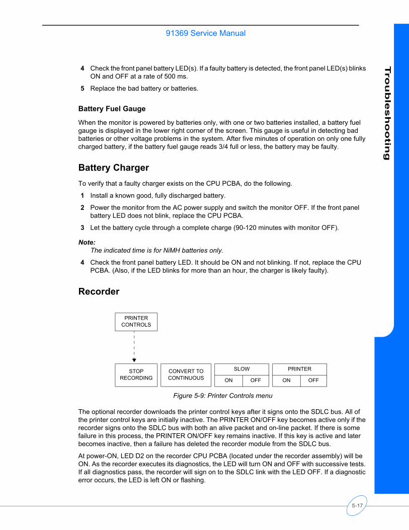
91369 Service ManualTro
ub
lesh
oo
ting
4 Check the front panel battery LED(s). If a faulty battery is detected, the front panel LED(s) blinks ON and OFF at a rate of 500 ms.
5 Replace the bad battery or batteries.
Battery Fuel Gauge
When the monitor is powered by batteries only, with one or two batteries installed, a battery fuel gauge is displayed in the lower right corner of the screen. This gauge is useful in detecting bad batteries or other voltage problems in the system. After five minutes of operation on only one fully charged battery, if the battery fuel gauge reads 3/4 full or less, the battery may be faulty.
Battery ChargerTo verify that a faulty charger exists on the CPU PCBA, do the following.
1 Install a known good, fully discharged battery.
2 Power the monitor from the AC power supply and switch the monitor OFF. If the front panel battery LED does not blink, replace the CPU PCBA.
3 Let the battery cycle through a complete charge (90-120 minutes with monitor OFF).
Note:The indicated time is for NiMH batteries only.
4 Check the front panel battery LED. It should be ON and not blinking. If not, replace the CPU PCBA. (Also, if the LED blinks for more than an hour, the charger is likely faulty).
Recorder
Figure 5-9: Printer Controls menu
The optional recorder downloads the printer control keys after it signs onto the SDLC bus. All of the printer control keys are initially inactive. The PRINTER ON/OFF key becomes active only if the recorder signs onto the SDLC bus with both an alive packet and on-line packet. If there is some failure in this process, the PRINTER ON/OFF key remains inactive. If this key is active and later becomes inactive, then a failure has deleted the recorder module from the SDLC bus.
At power-ON, LED D2 on the recorder CPU PCBA (located under the recorder assembly) will be ON. As the recorder executes its diagnostics, the LED will turn ON and OFF with successive tests. If all diagnostics pass, the recorder will sign on to the SDLC link with the LED OFF. If a diagnostic error occurs, the LED is left ON or flashing.
PRINTER CONTROLS
STOP RECORDING
CONVERT TO CONTINUOUS
SLOW PRINTER
ON OFF ON OFF
5-17
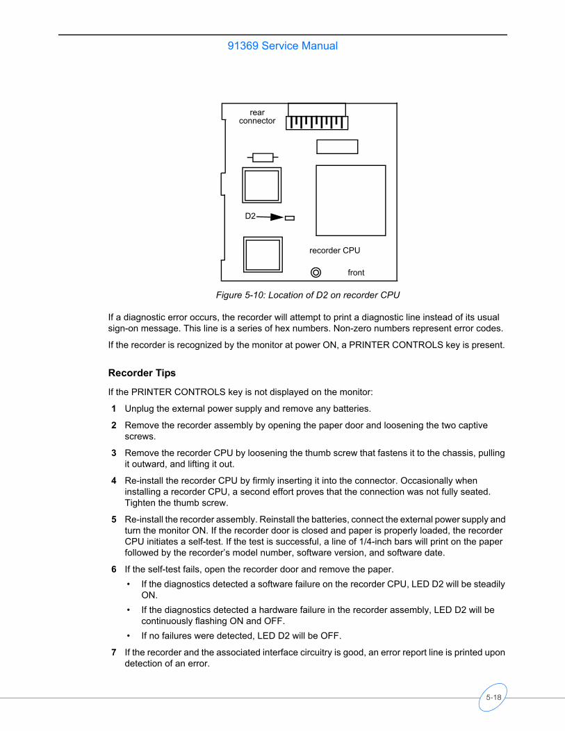
91369 Service Manual
Figure 5-10: Location of D2 on recorder CPU
If a diagnostic error occurs, the recorder will attempt to print a diagnostic line instead of its usual sign-on message. This line is a series of hex numbers. Non-zero numbers represent error codes.
If the recorder is recognized by the monitor at power ON, a PRINTER CONTROLS key is present.
Recorder Tips
If the PRINTER CONTROLS key is not displayed on the monitor:
1 Unplug the external power supply and remove any batteries.
2 Remove the recorder assembly by opening the paper door and loosening the two captive screws.
3 Remove the recorder CPU by loosening the thumb screw that fastens it to the chassis, pulling it outward, and lifting it out.
4 Re-install the recorder CPU by firmly inserting it into the connector. Occasionally when installing a recorder CPU, a second effort proves that the connection was not fully seated. Tighten the thumb screw.
5 Re-install the recorder assembly. Reinstall the batteries, connect the external power supply and turn the monitor ON. If the recorder door is closed and paper is properly loaded, the recorder CPU initiates a self-test. If the test is successful, a line of 1/4-inch bars will print on the paper followed by the recorder’s model number, software version, and software date.
6 If the self-test fails, open the recorder door and remove the paper.• If the diagnostics detected a software failure on the recorder CPU, LED D2 will be steadily
ON.• If the diagnostics detected a hardware failure in the recorder assembly, LED D2 will be
continuously flashing ON and OFF.• If no failures were detected, LED D2 will be OFF.
7 If the recorder and the associated interface circuitry is good, an error report line is printed upon detection of an error.
D2
front
rearconnector
recorder CPU
5-18
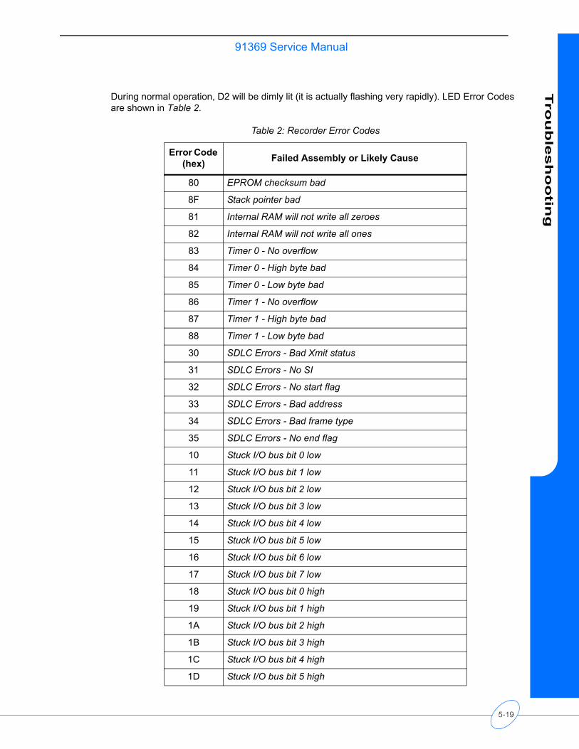
91369 Service ManualTro
ub
lesh
oo
ting
During normal operation, D2 will be dimly lit (it is actually flashing very rapidly). LED Error Codes are shown in Table 2.
Table 2: Recorder Error Codes
Error Code (hex) Failed Assembly or Likely Cause
80 EPROM checksum bad
8F Stack pointer bad
81 Internal RAM will not write all zeroes
82 Internal RAM will not write all ones
83 Timer 0 - No overflow
84 Timer 0 - High byte bad
85 Timer 0 - Low byte bad
86 Timer 1 - No overflow
87 Timer 1 - High byte bad
88 Timer 1 - Low byte bad
30 SDLC Errors - Bad Xmit status
31 SDLC Errors - No SI
32 SDLC Errors - No start flag
33 SDLC Errors - Bad address
34 SDLC Errors - Bad frame type
35 SDLC Errors - No end flag
10 Stuck I/O bus bit 0 low
11 Stuck I/O bus bit 1 low
12 Stuck I/O bus bit 2 low
13 Stuck I/O bus bit 3 low
14 Stuck I/O bus bit 4 low
15 Stuck I/O bus bit 5 low
16 Stuck I/O bus bit 6 low
17 Stuck I/O bus bit 7 low
18 Stuck I/O bus bit 0 high
19 Stuck I/O bus bit 1 high
1A Stuck I/O bus bit 2 high
1B Stuck I/O bus bit 3 high
1C Stuck I/O bus bit 4 high
1D Stuck I/O bus bit 5 high
5-19
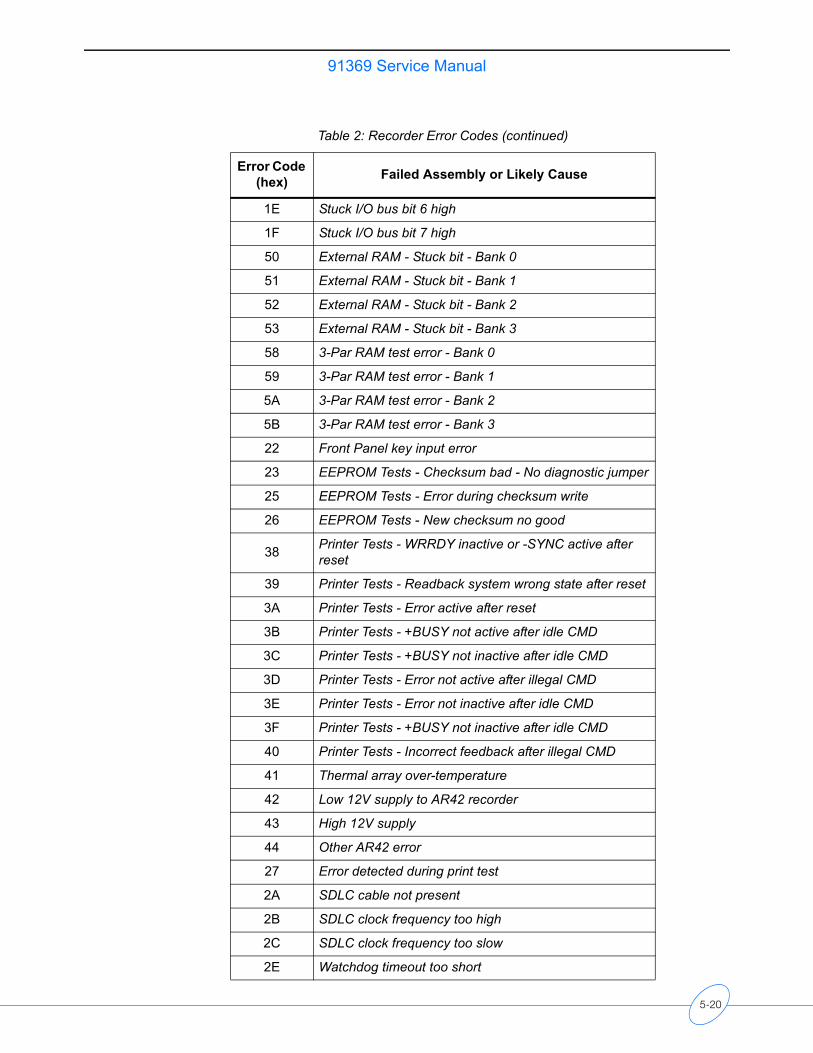
91369 Service Manual
1E Stuck I/O bus bit 6 high
1F Stuck I/O bus bit 7 high
50 External RAM - Stuck bit - Bank 0
51 External RAM - Stuck bit - Bank 1
52 External RAM - Stuck bit - Bank 2
53 External RAM - Stuck bit - Bank 3
58 3-Par RAM test error - Bank 0
59 3-Par RAM test error - Bank 1
5A 3-Par RAM test error - Bank 2
5B 3-Par RAM test error - Bank 3
22 Front Panel key input error
23 EEPROM Tests - Checksum bad - No diagnostic jumper
25 EEPROM Tests - Error during checksum write
26 EEPROM Tests - New checksum no good
38 Printer Tests - WRRDY inactive or -SYNC active after reset
39 Printer Tests - Readback system wrong state after reset
3A Printer Tests - Error active after reset
3B Printer Tests - +BUSY not active after idle CMD
3C Printer Tests - +BUSY not inactive after idle CMD
3D Printer Tests - Error not active after illegal CMD
3E Printer Tests - Error not inactive after idle CMD
3F Printer Tests - +BUSY not inactive after idle CMD
40 Printer Tests - Incorrect feedback after illegal CMD
41 Thermal array over-temperature
42 Low 12V supply to AR42 recorder
43 High 12V supply
44 Other AR42 error
27 Error detected during print test
2A SDLC cable not present
2B SDLC clock frequency too high
2C SDLC clock frequency too slow
2E Watchdog timeout too short
Table 2: Recorder Error Codes (continued)
Error Code (hex) Failed Assembly or Likely Cause
5-20
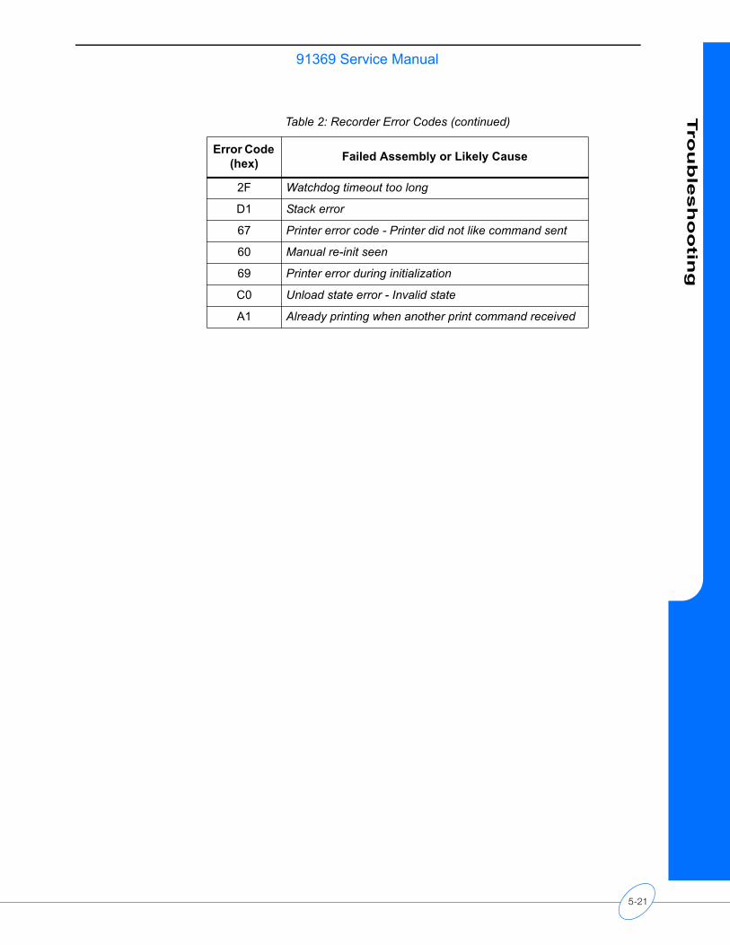
91369 Service ManualTro
ub
lesh
oo
ting
2F Watchdog timeout too long
D1 Stack error
67 Printer error code - Printer did not like command sent
60 Manual re-init seen
69 Printer error during initialization
C0 Unload state error - Invalid state
A1 Already printing when another print command received
Table 2: Recorder Error Codes (continued)
Error Code (hex) Failed Assembly or Likely Cause
5-21

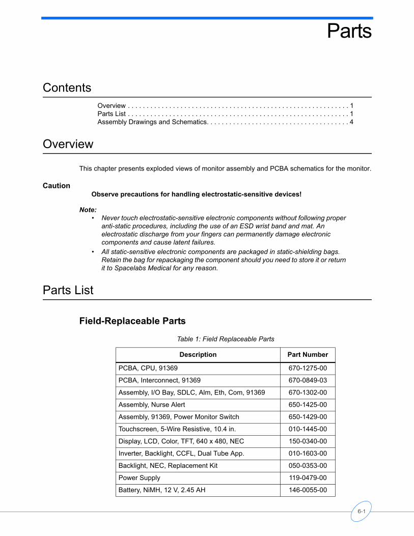
Parts
Contents
Overview . . . . . . . . . . . . . . . . . . . . . . . . . . . . . . . . . . . . . . . . . . . . . . . . . . . . . . . . . . . 1Parts List . . . . . . . . . . . . . . . . . . . . . . . . . . . . . . . . . . . . . . . . . . . . . . . . . . . . . . . . . . . 1Assembly Drawings and Schematics. . . . . . . . . . . . . . . . . . . . . . . . . . . . . . . . . . . . . . 4Overview
This chapter presents exploded views of monitor assembly and PCBA schematics for the monitor.
CautionObserve precautions for handling electrostatic-sensitive devices!
Note:• Never touch electrostatic-sensitive electronic components without following proper
anti-static procedures, including the use of an ESD wrist band and mat. An electrostatic discharge from your fingers can permanently damage electronic components and cause latent failures.
• All static-sensitive electronic components are packaged in static-shielding bags. Retain the bag for repackaging the component should you need to store it or return it to Spacelabs Medical for any reason.
Parts List
Field-Replaceable Parts
Table 1: Field Replaceable Parts
Description Part Number
PCBA, CPU, 91369 670-1275-00
PCBA, Interconnect, 91369 670-0849-03
Assembly, I/O Bay, SDLC, Alm, Eth, Com, 91369 670-1302-00
Assembly, Nurse Alert 650-1425-00
Assembly, 91369, Power Monitor Switch 650-1429-00
Touchscreen, 5-Wire Resistive, 10.4 in. 010-1445-00
Display, LCD, Color, TFT, 640 x 480, NEC 150-0340-00
Inverter, Backlight, CCFL, Dual Tube App. 010-1603-00
Backlight, NEC, Replacement Kit 050-0353-00
Power Supply 119-0479-00
Battery, NiMH, 12 V, 2.45 AH 146-0055-00
6-1
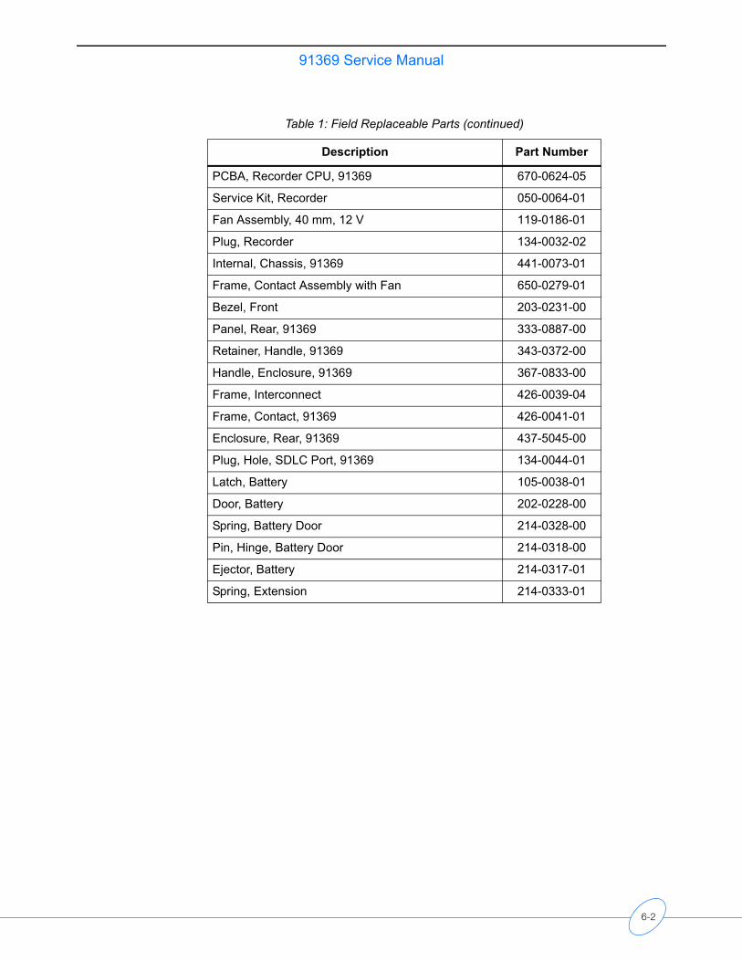
91369 Service Manual
PCBA, Recorder CPU, 91369 670-0624-05
Service Kit, Recorder 050-0064-01
Fan Assembly, 40 mm, 12 V 119-0186-01
Plug, Recorder 134-0032-02
Internal, Chassis, 91369 441-0073-01
Frame, Contact Assembly with Fan 650-0279-01
Bezel, Front 203-0231-00
Panel, Rear, 91369 333-0887-00
Retainer, Handle, 91369 343-0372-00
Handle, Enclosure, 91369 367-0833-00
Frame, Interconnect 426-0039-04
Frame, Contact, 91369 426-0041-01
Enclosure, Rear, 91369 437-5045-00
Plug, Hole, SDLC Port, 91369 134-0044-01
Latch, Battery 105-0038-01
Door, Battery 202-0228-00
Spring, Battery Door 214-0328-00
Pin, Hinge, Battery Door 214-0318-00
Ejector, Battery 214-0317-01
Spring, Extension 214-0333-01
Table 1: Field Replaceable Parts (continued)
Description Part Number
6-2
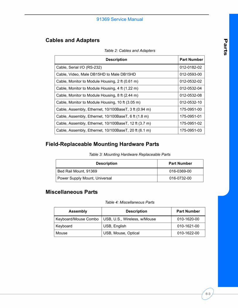
91369 Service ManualP
arts
Cables and Adapters
Field-Replaceable Mounting Hardware Parts
Miscellaneous Parts
Table 2: Cables and Adapters
Description Part Number
Cable, Serial I/O (RS-232) 012-0182-02
Cable, Video, Male DB15HD to Male DB15HD 012-0593-00
Cable, Monitor to Module Housing, 2 ft (0.61 m) 012-0532-02
Cable, Monitor to Module Housing, 4 ft (1.22 m) 012-0532-04
Cable, Monitor to Module Housing, 8 ft (2.44 m) 012-0532-08
Cable, Monitor to Module Housing, 10 ft (3.05 m) 012-0532-10
Cable, Assembly, Ethernet, 10/100BaseT, 3 ft (0.94 m) 175-0951-00
Cable, Assembly, Ethernet, 10/100BaseT, 6 ft (1.8 m) 175-0951-01
Cable, Assembly, Ethernet, 10/100BaseT, 12 ft (3.7 m) 175-0951-02
Cable, Assembly, Ethernet, 10/100BaseT, 20 ft (6.1 m) 175-0951-03
Table 3: Mounting Hardware Replaceable Parts
Description Part Number
Bed Rail Mount, 91369 016-0369-00
Power Supply Mount, Universal 016-0732-00
Table 4: Miscellaneous Parts
Assembly Description Part Number
Keyboard/Mouse Combo USB, U.S., Wireless, w/Mouse 010-1620-00
Keyboard USB, English 010-1621-00
Mouse USB, Mouse, Optical 010-1622-00
6-3
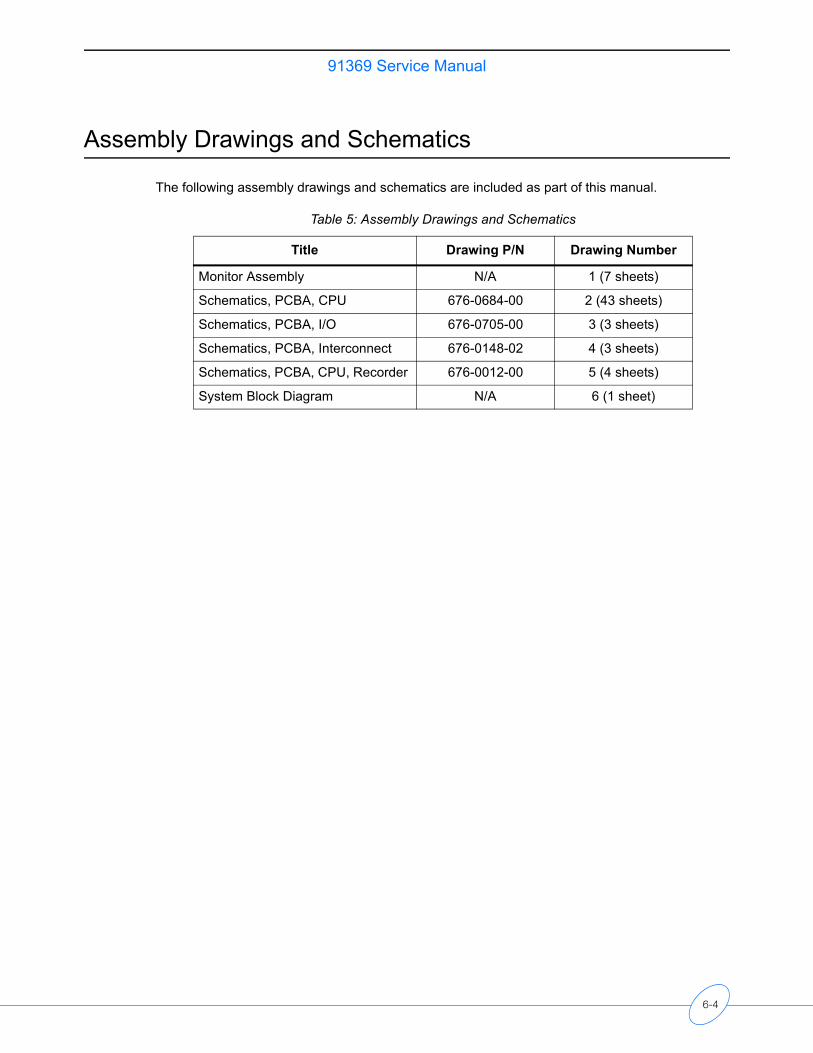
91369 Service Manual
Assembly Drawings and Schematics
The following assembly drawings and schematics are included as part of this manual.
Table 5: Assembly Drawings and Schematics
Title Drawing P/N Drawing Number
Monitor Assembly N/A 1 (7 sheets)
Schematics, PCBA, CPU 676-0684-00 2 (43 sheets)
Schematics, PCBA, I/O 676-0705-00 3 (3 sheets)
Schematics, PCBA, Interconnect 676-0148-02 4 (3 sheets)
Schematics, PCBA, CPU, Recorder 676-0012-00 5 (4 sheets)
System Block Diagram N/A 6 (1 sheet)
6-4
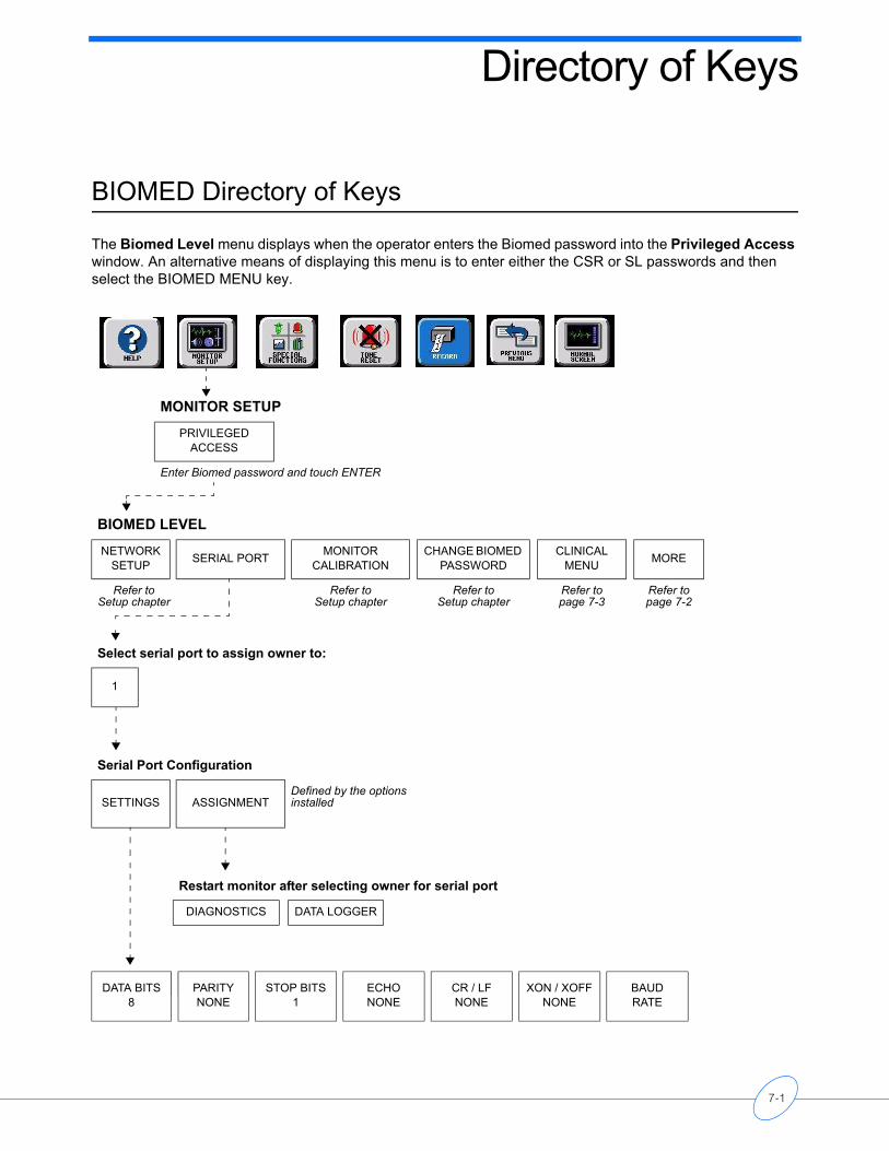
Directory of Keys
BIOMED Directory of Keys
The Biomed Level menu displays when the operator enters the Biomed password into the Privileged Access window. An alternative means of displaying this menu is to enter either the CSR or SL passwords and then select the BIOMED MENU key.
MONITOR SETUP
PRIVILEGED ACCESS
Enter Biomed password and touch ENTER
BIOMED LEVEL
NETWORK SETUP SERIAL PORT MONITOR
CALIBRATIONCHANGE BIOMED
PASSWORDCLINICAL
MENU MORE
Refer to Setup chapter
Refer to Setup chapter
Refer to Setup chapter
Refer to page 7-3
Refer to page 7-2
Select serial port to assign owner to:
1
Serial Port Configuration
SETTINGS ASSIGNMENTDefined by the options installed
Restart monitor after selecting owner for serial port
DIAGNOSTICS DATA LOGGER
DATA BITS8
PARITYNONE
STOP BITS1
ECHONONE
CR / LFNONE
XON / XOFFNONE
BAUDRATE
7-1
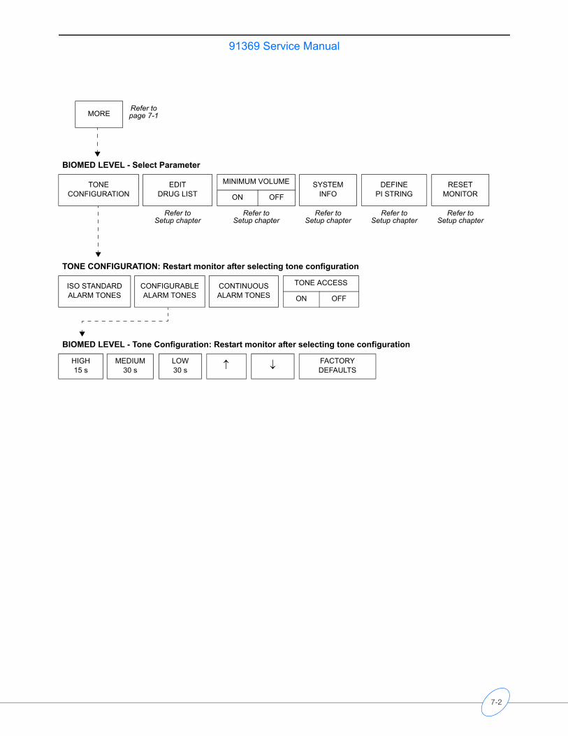
91369 Service Manual
MORERefer to page 7-1
BIOMED LEVEL - Select Parameter
TONECONFIGURATION
EDIT DRUG LIST
MINIMUM VOLUME SYSTEM INFO
DEFINE PI STRING
RESET MONITORON OFF
Refer to Setup chapter
Refer to Setup chapter
Refer to Setup chapter
Refer to Setup chapter
Refer to Setup chapter
TONE CONFIGURATION: Restart monitor after selecting tone configuration
ISO STANDARD ALARM TONES
CONFIGURABLE ALARM TONES
CONTINUOUS ALARM TONES
TONE ACCESS
ON OFF
BIOMED LEVEL - Tone Configuration: Restart monitor after selecting tone configuration
HIGH 15 s
MEDIUM 30 s
LOW 30 s ↑ ↓ FACTORY
DEFAULTS
7-2
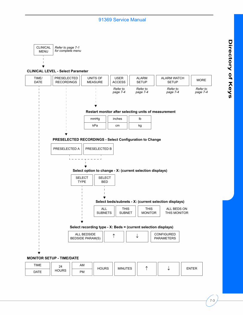
91369 Service ManualD
irecto
ry o
f Keys
CLINICAL MENU
Refer to page 7-1 for complete menu
CLINICAL LEVEL - Select Parameter
TIME/DATE
PRESELECTED RECORDINGS
UNITS OF MEASURE
USER ACCESS
ALARM SETUP
ALARM WATCH SETUP MORE
Refer to page 7-4
Refer to page 7-4
Refer to page 7-4
Refer to page 7-4
Restart monitor after selecting units of measurement
mmHg inches lb
kPa cm kg
PRESELECTED RECORDINGS - Select Configuration to Change
PRESELECTED A PRESELECTED B
Select option to change - X: (current selection displays)
SELECT TYPE
SELECT BED
Select beds/subnets - X: (current selection displays)
ALL SUBNETS
THIS SUBNET
THIS MONITOR
ALL BEDS ON THIS MONITOR
Select recording type - X: Beds = (current selection displays)
ALL BEDSIDE BEDSIDE PARAM(S) ↑ ↓ CONFIGURED
PARAMETERS
MONITOR SETUP - TIME/DATE
TIME 24 HOURS
AMHOURS MINUTES ↑ ↓ ENTER
DATE PM
7-3
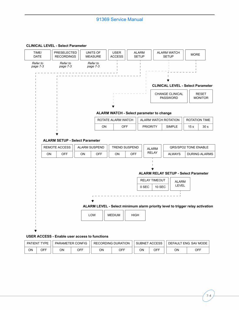
91369 Service Manual
CLINICAL LEVEL - Select Parameter
TIME/DATE
PRESELECTED RECORDINGS
UNITS OF MEASURE
USER ACCESS
ALARM SETUP
ALARM WATCH SETUP MORE
Refer topage 7-3
Refer to page 7-3
Refer to page 7-3
CLINICAL LEVEL - Select Parameter
CHANGE CLINICAL PASSWORD
RESET MONITOR
ALARM WATCH - Select parameter to change
ROTATE ALARM WATCH ALARM WATCH ROTATION ROTATION TIME
ON OFF PRIORITY SIMPLE 15 s 30 s
ALARM SETUP - Select Parameter
REMOTE ACCESS ALARM SUSPEND TREND SUSPEND ALARM RELAY
QRS/SPO2 TONE ENABLE
ON OFF ON OFF ON OFF ALWAYS DURING ALARMS
ALARM RELAY SETUP - Select Parameter
RELAY TIMEOUT ALARM LEVEL0 SEC 10 SEC
ALARM LEVEL - Select minimum alarm priority level to trigger relay activation
LOW MEDIUM HIGH
USER ACCESS - Enable user access to functions
PATIENT TYPE PARAMETER CONFIG RECORDING DURATION SUBNET ACCESS DEFAULT ENG. SAV MODE
ON OFF ON OFF ON OFF ON OFF ON OFF
7-4

Glossary
The following terms appear in this manual:
ASCIIAmerican Standard Code for Information Interchange. A standardized way of assigning numerical codes to characters and control codes.
ATEAutomated test equipment used in performance testing of printed circuit assemblies.
Baud rateData transfer rate associated with serial data transfers, typically between personal computers via modems. Example: 9600 bits per second.
Bit mapTechnique of drawing computer images by mapping the image in RAM.
BNCA push and twist connector that allows a fast connect/disconnect of thin coaxial cable.
Boot ROMProgrammed ROM devices that contain basic data required to start a digital system at power up. This data generates instructions to the processor, allowing a limited set of start-up instructions.
CMOS RAMBattery backed up device used to store configuration information such as node name, node ID, or bed names.
Composite videoVideo display signal containing both video and sync information.
CPUCentral Processing Unit
CR/LFCarriage Return / Line Feed
CTS Clear To Send signal used in communication protocols.
DB9“D” shaped, 9-pin connector of either male or female gender.
DB15“D” shaped, 15-pin connector of either male or female gender.
DB15HDHigh-density, “D” shaped, 15-pin connector with DB9 shell and footprint.
DB26“D” shaped, 26-pin connector of either male or female gender.
DegaussProcess of removing a magnetic charge from a material. Color CRT screens are most susceptible to this type of charge creating “purity” problems.
Dot pitchMethod of comparison used to determine the quality of a display. It indicates the angle and proximity each dot has to the other.
DRAM Dynamic Random Access Memory used for computer memory systems.
DTR Data Terminal Ready signal used in communications protocol.
EEPROMElectrically Erasable Programmable Read Only Memory. The portion of the monitor’s memory which holds sysgen information and hardware configurations.
EMIElectromagnetic Interference generated by repetitive signals such as microprocessor clocks that can interfere with other devices or two-way radio communications.
EPPEnhanced Parallel Port
ESDElectrostatic Discharge. High voltage potentials carried on the body that are generated by walking across a carpeted floor or caused by low humidity environments, which can be discharged into an electronic device, damaging it.
EthernetThe LAN technology that uses CSMA/CD physical access method and 10/100 Mbps digital transmission. The forerunner of the IEEE802.3 CSMA/CD standard.
FerriteRF (radio frequency) glossy material used in EMI suppression.
FPGAField-Programmable Gate Array.
8-1
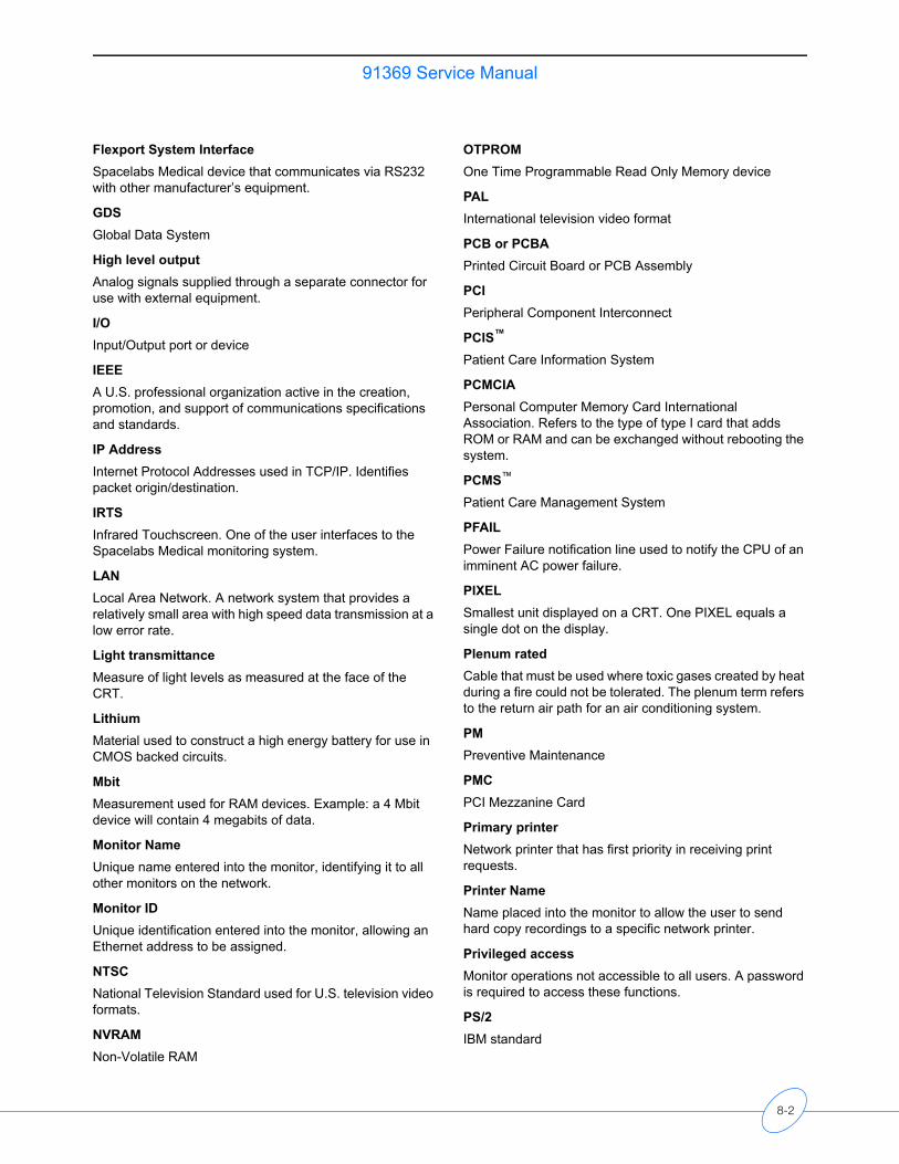
91369 Service Manual
Flexport System InterfaceSpacelabs Medical device that communicates via RS232 with other manufacturer’s equipment.
GDSGlobal Data System
High level outputAnalog signals supplied through a separate connector for use with external equipment.
I/OInput/Output port or device
IEEEA U.S. professional organization active in the creation, promotion, and support of communications specifications and standards.
IP AddressInternet Protocol Addresses used in TCP/IP. Identifies packet origin/destination.
IRTSInfrared Touchscreen. One of the user interfaces to the Spacelabs Medical monitoring system.
LANLocal Area Network. A network system that provides a relatively small area with high speed data transmission at a low error rate.
Light transmittanceMeasure of light levels as measured at the face of the CRT.
LithiumMaterial used to construct a high energy battery for use in CMOS backed circuits.
MbitMeasurement used for RAM devices. Example: a 4 Mbit device will contain 4 megabits of data.
Monitor NameUnique name entered into the monitor, identifying it to all other monitors on the network.
Monitor IDUnique identification entered into the monitor, allowing an Ethernet address to be assigned.
NTSCNational Television Standard used for U.S. television video formats.
NVRAMNon-Volatile RAM
OTPROMOne Time Programmable Read Only Memory device
PALInternational television video format
PCB or PCBAPrinted Circuit Board or PCB Assembly
PCIPeripheral Component Interconnect
PCIS™
Patient Care Information System
PCMCIAPersonal Computer Memory Card International Association. Refers to the type of type I card that adds ROM or RAM and can be exchanged without rebooting the system.
PCMS™
Patient Care Management System
PFAILPower Failure notification line used to notify the CPU of an imminent AC power failure.
PIXELSmallest unit displayed on a CRT. One PIXEL equals a single dot on the display.
Plenum ratedCable that must be used where toxic gases created by heat during a fire could not be tolerated. The plenum term refers to the return air path for an air conditioning system.
PMPreventive Maintenance
PMCPCI Mezzanine Card
Primary printerNetwork printer that has first priority in receiving print requests.
Printer NameName placed into the monitor to allow the user to send hard copy recordings to a specific network printer.
Privileged accessMonitor operations not accessible to all users. A password is required to access these functions.
PS/2IBM standard
8-2
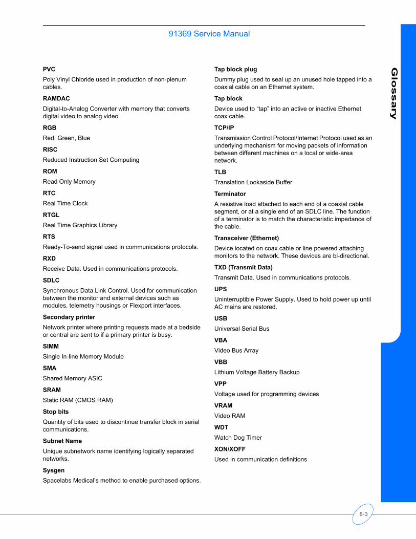
91369 Service ManualG
lossary
PVCPoly Vinyl Chloride used in production of non-plenum cables.
RAMDACDigital-to-Analog Converter with memory that converts digital video to analog video.
RGBRed, Green, Blue
RISCReduced Instruction Set Computing
ROMRead Only Memory
RTCReal Time Clock
RTGLReal Time Graphics Library
RTS Ready-To-send signal used in communications protocols.
RXD Receive Data. Used in communications protocols.
SDLCSynchronous Data Link Control. Used for communication between the monitor and external devices such as modules, telemetry housings or Flexport interfaces.
Secondary printerNetwork printer where printing requests made at a bedside or central are sent to if a primary printer is busy.
SIMMSingle In-line Memory Module
SMAShared Memory ASIC
SRAMStatic RAM (CMOS RAM)
Stop bitsQuantity of bits used to discontinue transfer block in serial communications.
Subnet NameUnique subnetwork name identifying logically separated networks.
SysgenSpacelabs Medical’s method to enable purchased options.
Tap block plugDummy plug used to seal up an unused hole tapped into a coaxial cable on an Ethernet system.
Tap blockDevice used to “tap” into an active or inactive Ethernet coax cable.
TCP/IPTransmission Control Protocol/Internet Protocol used as an underlying mechanism for moving packets of information between different machines on a local or wide-area network.
TLBTranslation Lookaside Buffer
TerminatorA resistive load attached to each end of a coaxial cable segment, or at a single end of an SDLC line. The function of a terminator is to match the characteristic impedance of the cable.
Transceiver (Ethernet)Device located on coax cable or line powered attaching monitors to the network. These devices are bi-directional.
TXD (Transmit Data)Transmit Data. Used in communications protocols.
UPSUninterruptible Power Supply. Used to hold power up until AC mains are restored.
USBUniversal Serial Bus
VBAVideo Bus Array
VBBLithium Voltage Battery Backup
VPPVoltage used for programming devices
VRAMVideo RAM
WDTWatch Dog Timer
XON/XOFFUsed in communication definitions
8-3


Appendix A - ElectromagneticCompatibility
Contents
Electromagnetic Emissions . . . . . . . . . . . . . . . . . . . . . . . . . . . . . . . . . . . . . . . . . . . . . 1Electromagnetic Immunity . . . . . . . . . . . . . . . . . . . . . . . . . . . . . . . . . . . . . . . . . . . . . . 1Separation Distances . . . . . . . . . . . . . . . . . . . . . . . . . . . . . . . . . . . . . . . . . . . . . . . . . 3Electromagnetic Emissions
Electromagnetic Immunity
Note:The monitor is intended for use in the electromagnetic environment specified below. The customer, or user, of the monitor should ensure that it is used in such an environment
Emission Test Compliance Electromagnetic Environment
RF emissions CISPR 11
Group 1Class B
The monitor uses RF energy only for internal function. Therefore, RF emissions are very low and are not likely to cause any interference in nearby electronic equipment
Harmonic emissions IEC 61000-3-2 Complies Device Class A
Voltage fluctuations/flicker IEC 61000-3-3
Complies
Immunity Test IEC 60601 Test Level Compliance Level Electromagnetic Environment
Electrostatic discharge (ESD)IEC 61000-4-2
±6 kV contact±8 kV air
8 kV contact15 kV air
Floors should be wood, concrete, or ceramic tile. If floors are covered with synthetic material, the relative humidity should be at least 30%.
Electrical fast transient/burstIEC 61000-4-4
±2 kV for power supply lines±1 kV for input/output data lines
±2 kV for power supply lines±1 kV for input/output data lines
Mains power quality should be that of a typical commercial or hospital environment.
SurgeIEC 61000-4-5
±1 kV differential mode±2 kV common mode
1 kV differential mode2 kV common mode
Mains power quality should be that of a typical commercial or hospital environment.
9-1
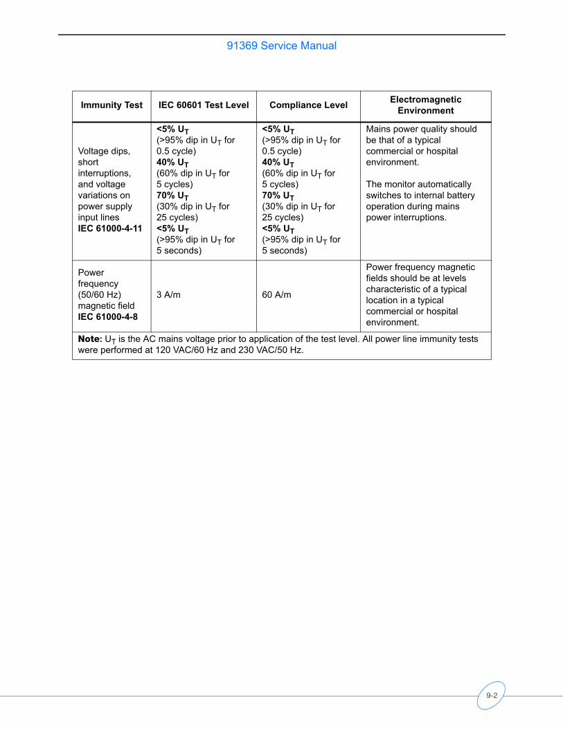
91369 Service Manual
Voltage dips, short interruptions, and voltage variations on power supply input lines IEC 61000-4-11
<5% UT(>95% dip in UT for 0.5 cycle)40% UT(60% dip in UT for 5 cycles)70% UT(30% dip in UT for 25 cycles)<5% UT(>95% dip in UT for 5 seconds)
<5% UT(>95% dip in UT for 0.5 cycle)40% UT(60% dip in UT for 5 cycles)70% UT(30% dip in UT for 25 cycles)<5% UT(>95% dip in UT for 5 seconds)
Mains power quality should be that of a typical commercial or hospital environment.
The monitor automatically switches to internal battery operation during mains power interruptions.
Power frequency(50/60 Hz)magnetic fieldIEC 61000-4-8
3 A/m 60 A/m
Power frequency magnetic fields should be at levels characteristic of a typical location in a typical commercial or hospital environment.
Note: UT is the AC mains voltage prior to application of the test level. All power line immunity tests were performed at 120 VAC/60 Hz and 230 VAC/50 Hz.
Immunity Test IEC 60601 Test Level Compliance Level Electromagnetic Environment
9-2
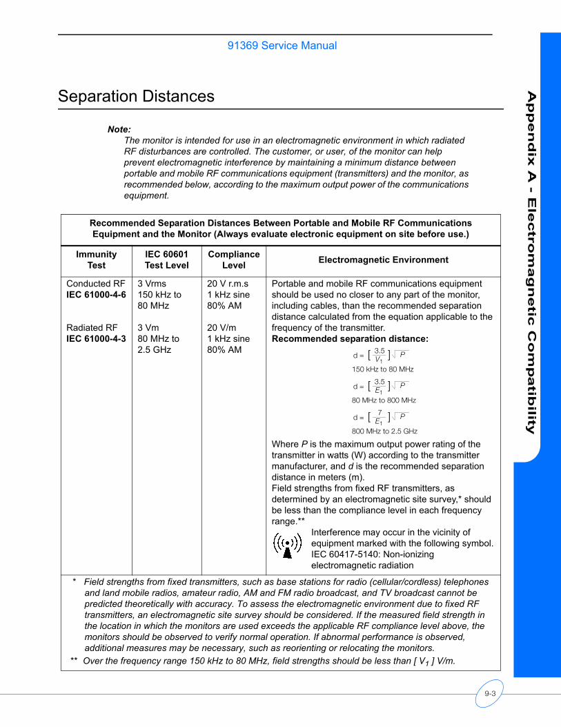
91369 Service ManualA
pp
en
dix
A - E
lectro
mag
netic
Co
mp
atib
ility
Separation Distances
Note:The monitor is intended for use in an electromagnetic environment in which radiated RF disturbances are controlled. The customer, or user, of the monitor can help prevent electromagnetic interference by maintaining a minimum distance between portable and mobile RF communications equipment (transmitters) and the monitor, as recommended below, according to the maximum output power of the communications equipment.
Recommended Separation Distances Between Portable and Mobile RF Communications Equipment and the Monitor (Always evaluate electronic equipment on site before use.)
Immunity Test
IEC 60601 Test Level
Compliance Level Electromagnetic Environment
Conducted RFIEC 61000-4-6
Radiated RFIEC 61000-4-3
3 Vrms150 kHz to 80 MHz
3 Vm80 MHz to 2.5 GHz
20 V r.m.s1 kHz sine80% AM
20 V/m1 kHz sine80% AM
Portable and mobile RF communications equipment should be used no closer to any part of the monitor, including cables, than the recommended separation distance calculated from the equation applicable to the frequency of the transmitter.Recommended separation distance:
Where P is the maximum output power rating of the transmitter in watts (W) according to the transmitter manufacturer, and d is the recommended separation distance in meters (m).Field strengths from fixed RF transmitters, as determined by an electromagnetic site survey,* should be less than the compliance level in each frequency range.**
Interference may occur in the vicinity of equipment marked with the following symbol.IEC 60417-5140: Non-ionizing electromagnetic radiation
* Field strengths from fixed transmitters, such as base stations for radio (cellular/cordless) telephones and land mobile radios, amateur radio, AM and FM radio broadcast, and TV broadcast cannot be predicted theoretically with accuracy. To assess the electromagnetic environment due to fixed RF transmitters, an electromagnetic site survey should be considered. If the measured field strength in the location in which the monitors are used exceeds the applicable RF compliance level above, the monitors should be observed to verify normal operation. If abnormal performance is observed, additional measures may be necessary, such as reorienting or relocating the monitors.
** Over the frequency range 150 kHz to 80 MHz, field strengths should be less than [ V1 ] V/m.
d = [ 3.5V1
] P
150 kHz to 80 MHz
d = [ 3.5E1
] P
80 MHz to 800 MHz
d = [ 7E1
] P
800 MHz to 2.5 GHz
9-3
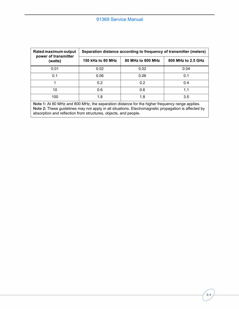
91369 Service Manual
Rated maximum output power of transmitter
(watts)
Separation distance according to frequency of transmitter (meters)
150 kHz to 80 MHz 80 MHz to 800 MHz 800 MHz to 2.5 GHz
0.01 0.02 0.02 0.04
0.1 0.06 0.06 0.1
1 0.2 0.2 0.4
10 0.6 0.6 1.1
100 1.8 1.8 3.5
Note 1: At 80 MHz and 800 MHz, the separation distance for the higher frequency range applies.Note 2: These guidelines may not apply in all situations. Electromagnetic propagation is affected by absorption and reflection from structures, objects, and people.
9-4
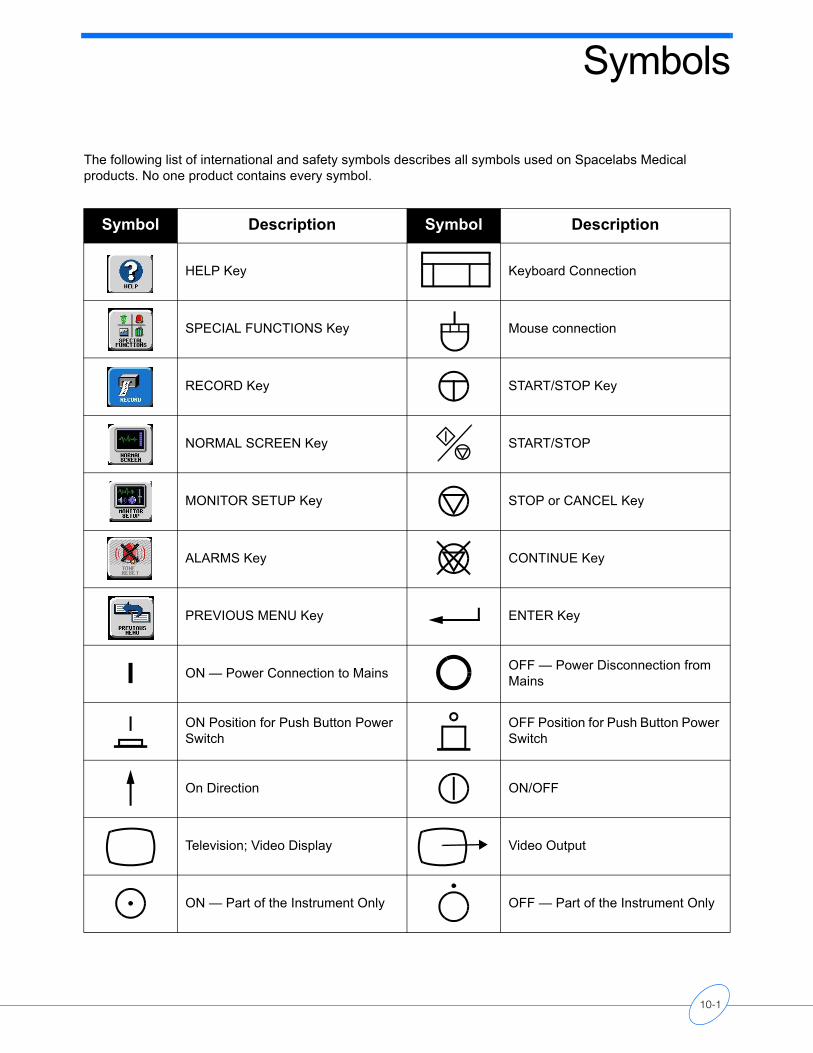
Symbols
The following list of international and safety symbols describes all symbols used on Spacelabs Medical products. No one product contains every symbol.
Symbol Description Symbol Description
HELP Key Keyboard Connection
SPECIAL FUNCTIONS Key Mouse connection
RECORD Key START/STOP Key
NORMAL SCREEN Key START/STOP
MONITOR SETUP Key STOP or CANCEL Key
ALARMS Key CONTINUE Key
PREVIOUS MENU Key ENTER Key
ON — Power Connection to Mains OFF — Power Disconnection from Mains
ON Position for Push Button Power Switch
OFF Position for Push Button Power Switch
On Direction ON/OFF
Television; Video Display Video Output
ON — Part of the Instrument Only OFF — Part of the Instrument Only
10-1
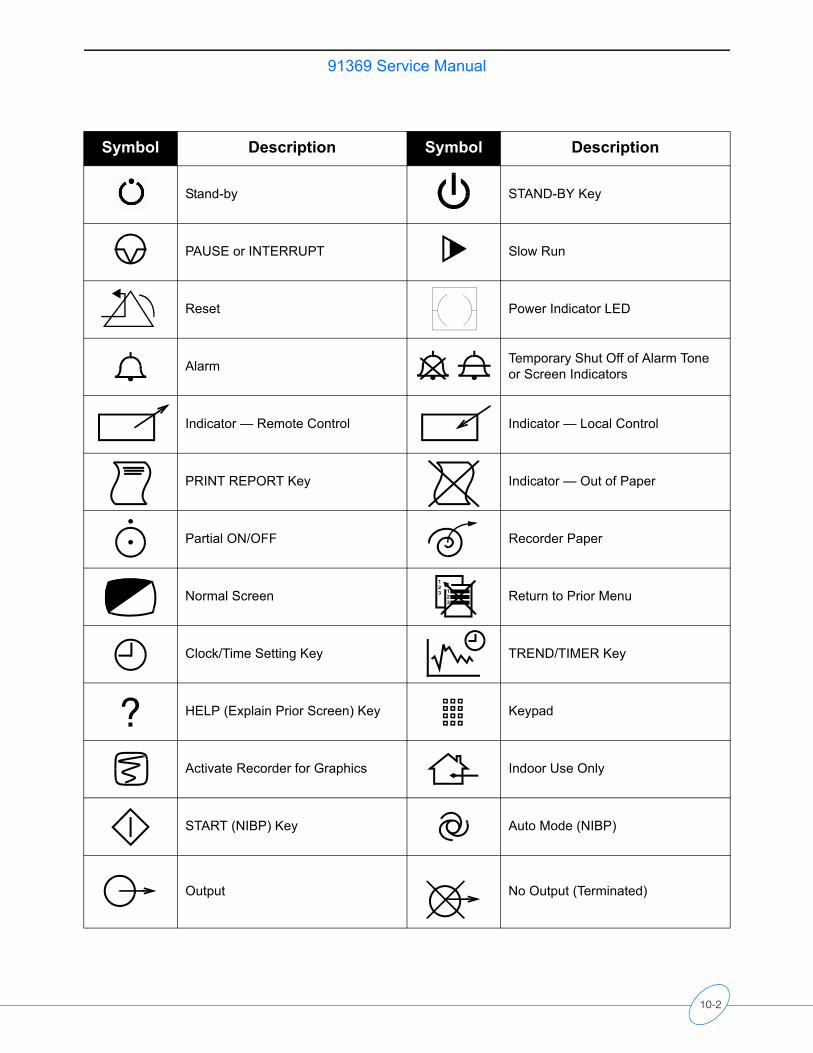
91369 Service Manual
Stand-by STAND-BY Key
PAUSE or INTERRUPT Slow Run
Reset Power Indicator LED
Alarm Temporary Shut Off of Alarm Tone or Screen Indicators
Indicator — Remote Control Indicator — Local Control
PRINT REPORT Key Indicator — Out of Paper
Partial ON/OFF Recorder Paper
Normal Screen Return to Prior Menu
Clock/Time Setting Key TREND/TIMER Key
HELP (Explain Prior Screen) Key Keypad
Activate Recorder for Graphics Indoor Use Only
START (NIBP) Key Auto Mode (NIBP)
Output No Output (Terminated)
Symbol Description Symbol Description
123 1
23
?
10-2
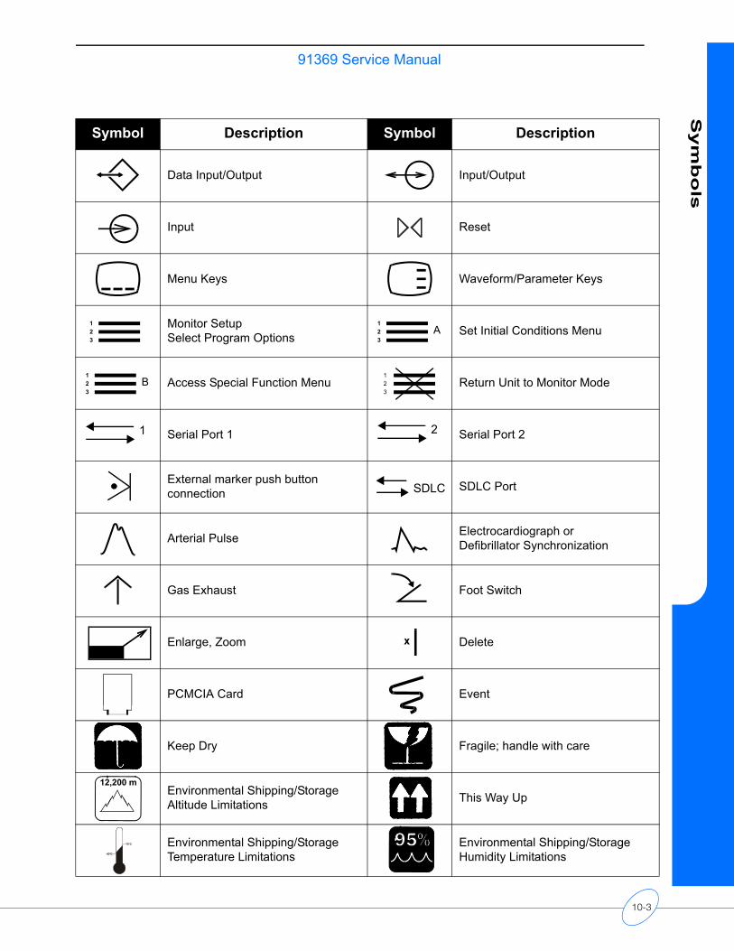
91369 Service ManualS
ym
bo
ls
Data Input/Output Input/Output
Input Reset
Menu Keys Waveform/Parameter Keys
Monitor SetupSelect Program Options Set Initial Conditions Menu
Access Special Function Menu Return Unit to Monitor Mode
Serial Port 1 Serial Port 2
External marker push button connection SDLC Port
Arterial Pulse Electrocardiograph or Defibrillator Synchronization
Gas Exhaust Foot Switch
Enlarge, Zoom Delete
PCMCIA Card Event
Keep Dry Fragile; handle with care
Environmental Shipping/Storage Altitude Limitations This Way Up
Environmental Shipping/StorageTemperature Limitations
Environmental Shipping/StorageHumidity Limitations
Symbol Description Symbol Description
123
123
A
123
B123
1 2
SDLC
x
12,200 m
10-3
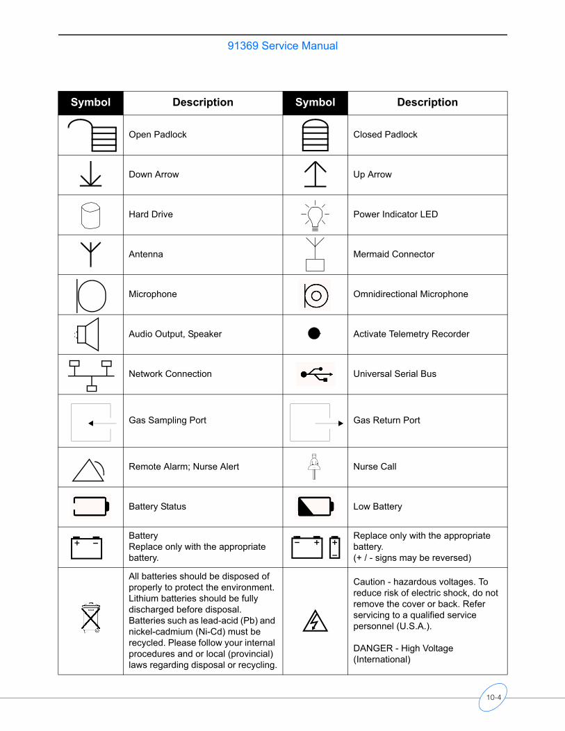
91369 Service Manual
Open Padlock Closed Padlock
Down Arrow Up Arrow
Hard Drive Power Indicator LED
Antenna Mermaid Connector
Microphone Omnidirectional Microphone
Audio Output, Speaker Activate Telemetry Recorder
Network Connection Universal Serial Bus
Gas Sampling Port Gas Return Port
Remote Alarm; Nurse Alert Nurse Call
Battery Status Low Battery
BatteryReplace only with the appropriate battery.
Replace only with the appropriate battery.(+ / - signs may be reversed)
All batteries should be disposed of properly to protect the environment. Lithium batteries should be fully discharged before disposal. Batteries such as lead-acid (Pb) and nickel-cadmium (Ni-Cd) must be recycled. Please follow your internal procedures and or local (provincial) laws regarding disposal or recycling.
Caution - hazardous voltages. To reduce risk of electric shock, do not remove the cover or back. Refer servicing to a qualified service personnel (U.S.A.).
DANGER - High Voltage (International)
Symbol Description Symbol Description
10-4
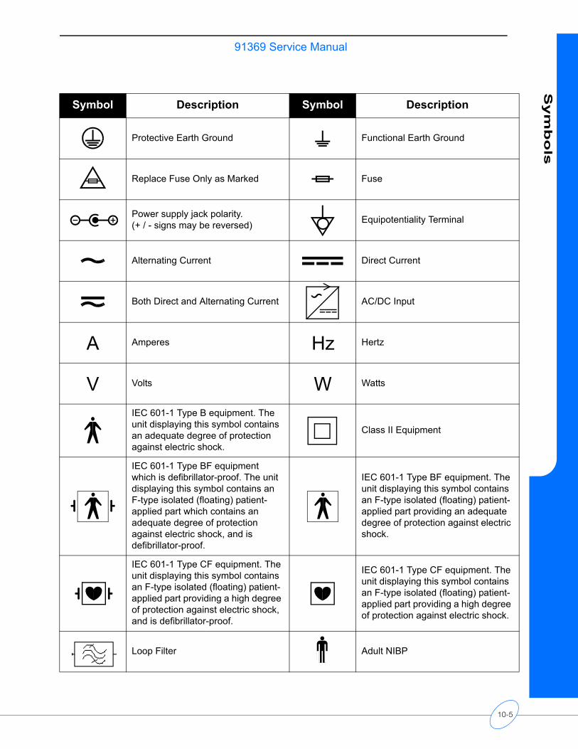
91369 Service ManualS
ym
bo
ls
Protective Earth Ground Functional Earth Ground
Replace Fuse Only as Marked Fuse
Power supply jack polarity. (+ / - signs may be reversed) Equipotentiality Terminal
Alternating Current Direct Current
Both Direct and Alternating Current AC/DC Input
Amperes Hertz
Volts Watts
IEC 601-1 Type B equipment. The unit displaying this symbol contains an adequate degree of protection against electric shock.
Class II Equipment
IEC 601-1 Type BF equipment which is defibrillator-proof. The unit displaying this symbol contains an F-type isolated (floating) patient-applied part which contains an adequate degree of protection against electric shock, and is defibrillator-proof.
IEC 601-1 Type BF equipment. The unit displaying this symbol contains an F-type isolated (floating) patient-applied part providing an adequate degree of protection against electric shock.
IEC 601-1 Type CF equipment. The unit displaying this symbol contains an F-type isolated (floating) patient-applied part providing a high degree of protection against electric shock, and is defibrillator-proof.
IEC 601-1 Type CF equipment. The unit displaying this symbol contains an F-type isolated (floating) patient-applied part providing a high degree of protection against electric shock.
Loop Filter Adult NIBP
Symbol Description Symbol Description
A Hz
V W
10-5
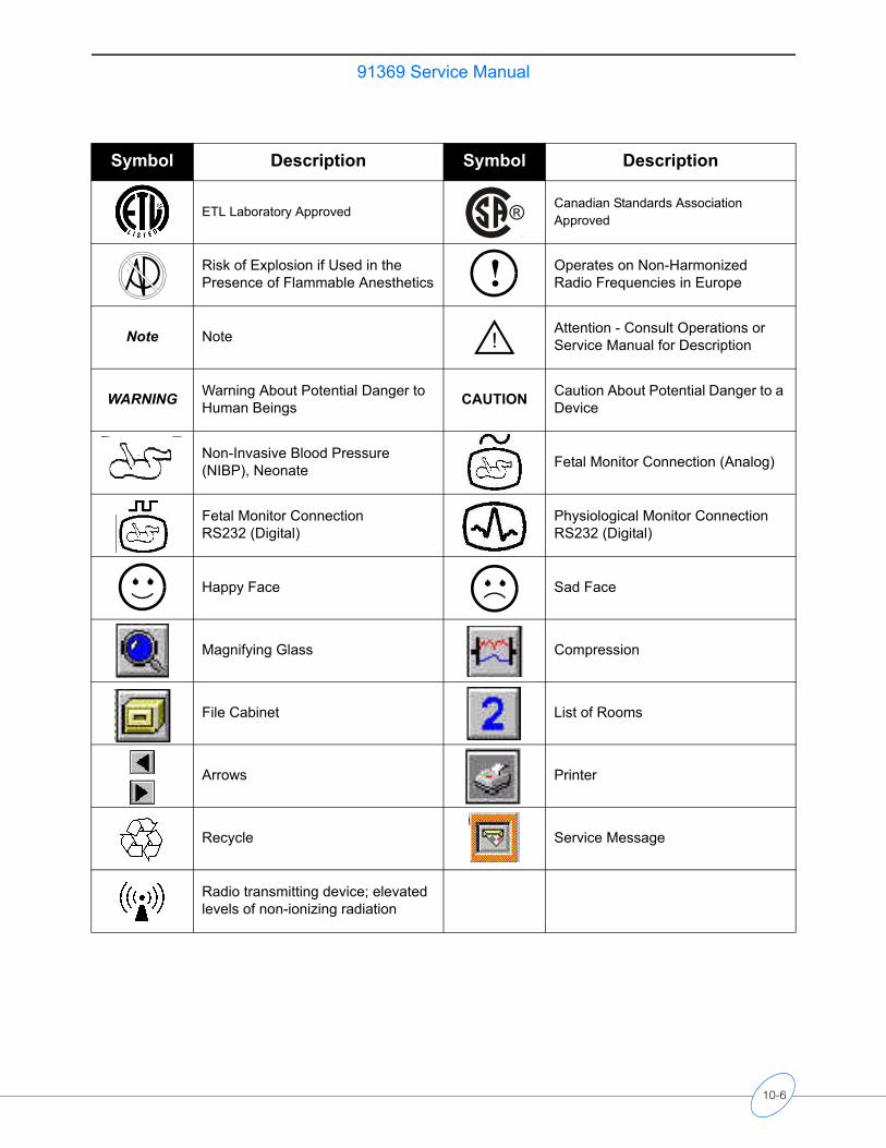
91369 Service Manual
ETL Laboratory ApprovedCanadian Standards Association Approved
Risk of Explosion if Used in the Presence of Flammable Anesthetics
Operates on Non-Harmonized Radio Frequencies in Europe
Note Note Attention - Consult Operations or Service Manual for Description
WARNING Warning About Potential Danger to Human Beings CAUTION Caution About Potential Danger to a
Device
Non-Invasive Blood Pressure (NIBP), Neonate Fetal Monitor Connection (Analog)
Fetal Monitor Connection RS232 (Digital)
Physiological Monitor Connection RS232 (Digital)
Happy Face Sad Face
Magnifying Glass Compression
File Cabinet List of Rooms
Arrows Printer
Recycle Service Message
Radio transmitting device; elevated levels of non-ionizing radiation
Symbol Description Symbol Description
®C US
!!
10-6
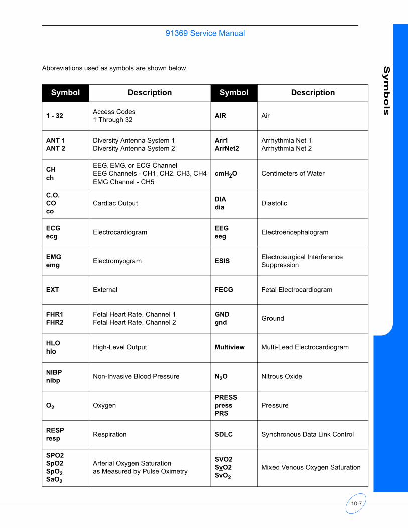
91369 Service ManualS
ym
bo
ls
Abbreviations used as symbols are shown below.
Symbol Description Symbol Description
1 - 32 Access Codes1 Through 32 AIR Air
ANT 1ANT 2
Diversity Antenna System 1Diversity Antenna System 2
Arr1ArrNet2
Arrhythmia Net 1Arrhythmia Net 2
CHch
EEG, EMG, or ECG ChannelEEG Channels - CH1, CH2, CH3, CH4EMG Channel - CH5
cmH2O Centimeters of Water
C.O.COco
Cardiac Output DIAdia Diastolic
ECGecg Electrocardiogram EEG
eeg Electroencephalogram
EMGemg Electromyogram ESIS Electrosurgical Interference
Suppression
EXT External FECG Fetal Electrocardiogram
FHR1FHR2
Fetal Heart Rate, Channel 1Fetal Heart Rate, Channel 2
GNDgnd Ground
HLOhlo High-Level Output Multiview Multi-Lead Electrocardiogram
NIBPnibp Non-Invasive Blood Pressure N2O Nitrous Oxide
O2 OxygenPRESSpressPRS
Pressure
RESPresp Respiration SDLC Synchronous Data Link Control
SPO2SpO2SpO2SaO2
Arterial Oxygen Saturation as Measured by Pulse Oximetry
SVO2SvO2SvO2
Mixed Venous Oxygen Saturation
10-7
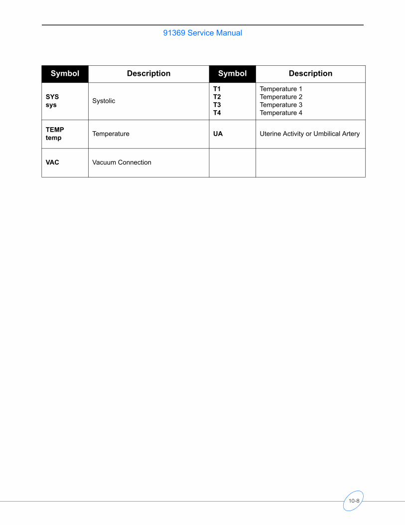
91369 Service Manual
SYSsys Systolic
T1T2T3T4
Temperature 1Temperature 2Temperature 3Temperature 4
TEMPtemp Temperature UA Uterine Activity or Umbilical Artery
VAC Vacuum Connection
Symbol Description Symbol Description
10-8