Embed Size (px)
Citation preview
Wedge ThreadTM
Field HandbookFourth Edition
Telephone
CanadaCalgary 403-531-1590
Nisku 780-955-2045
IndonesiaBatam 62-778-711318
MexicoVeracruz 52-298-10213
52-298-10230
52-298-10233
Villahermosa 52-931-44944
52-931-44942
Ciudad del Carmen 52-938-21053
52-938-21085
Reynosa 52-89-252360
52-89-252361
Telephone
NigeriaPort Harcourt 234-84-332281
Warri 234-53-252565
Republic of SingaporeSingapore 65-261-2566
United KingdomAberdeen, Scotland 441-224-878824
United StatesCalifornia, Bakersfield 661-588-9332
Louisiana,Westwego 504-348-3348
Texas, Houston 281-449-2000
713-670-3500
Texas, Odessa 915-552-7850
Wyoming, Casper 307-266-2120
VenezuelaPuerto La Cruz 58-281-2762083
58-281-2741651
Worldwide Sales, Service and Manufacturing
HYDRIL COMPANY INTERNATIONAL TUBULAR SALESP.O. Box 60458 Minto AvenueHouston, Texas 77205-0458 Altens Industrial EstateU.S.A. Aberdeen, AB1 3JZ ScotlandTelephone: 281.985.3412 Telephone: +44.1224.299.554Fax: 281.985.3376 Fax: +44.1224.299.578E-mail: [email protected] E-mail: [email protected]
Wedge Thread Field Handbook
2 27
Index of Tables
BSR For Drill Collars . . . . . . . . . . . . . . . . . . . . . . . . . . . . . . . . . . . . . . . . . . . . . . . . . . . 16
Back-Up Tong Distance From Face . . . . . . . . . . . . . . . . . . . . . . . . . . . . . . . . . . . . . . . . 22
Blanking Dimensions . . . . . . . . . . . . . . . . . . . . . . . . . . . . . . . . . . . . . . . . . . . . . . . . . . . 25
Box OD Swell Guidelines . . . . . . . . . . . . . . . . . . . . . . . . . . . . . . . . . . . . . . . . . . . . . . . 20
Capacities, Displacements and Equivalent Diameters. . . . . . . . . . . . . . . . . . . . . . . . . . 14
Drill Pipe Body Data . . . . . . . . . . . . . . . . . . . . . . . . . . . . . . . . . . . . . . . . . . . . . . . . . . . . 6
Kellyguard and Wedge Thread Tool Joint Options . . . . . . . . . . . . . . . . . . . . . . . . . . . . 26
Performance Data . . . . . . . . . . . . . . . . . . . . . . . . . . . . . . . . . . . . . . . . . . . . . . . . . . . . . . 3
Tension Versus Make-Up Torque . . . . . . . . . . . . . . . . . . . . . . . . . . . . . . . . . . . . . . . . . . 18
Tool Joint Dimensions . . . . . . . . . . . . . . . . . . . . . . . . . . . . . . . . . . . . . . . . . . . . . . . . . . . 5
Minimum Tong Space . . . . . . . . . . . . . . . . . . . . . . . . . . . . . . . . . . . . . . . . . . . . . . . . . . . 25
Wedge Thread Field Handbook
Wedge ThreadTM Field Handbook
PRODUCT
Wedge ThreadTM Drill Pipe Tool Joint . . . . . . . . . . . . . . . . . . . . . . . . . . . . . . . . . . . . . . . . . . .3
Pipe Body Data Tables . . . . . . . . . . . . . . . . . . . . . . . . . . . . . . . . . . . . . . . . . . . . . . . . . . . . . . . .6
Terminology . . . . . . . . . . . . . . . . . . . . . . . . . . . . . . . . . . . . . . . . . . . . . . . . . . . . . . . . . . . . . . .10
API Designations . . . . . . . . . . . . . . . . . . . . . . . . . . . . . . . . . . . . . . . . . . . . . . . . . . . . . . . . . . .11
Internal Coating Recommendation . . . . . . . . . . . . . . . . . . . . . . . . . . . . . . . . . . . . . . . . . . . .12
Capacities, Displacements, and Equivalent Diameters . . . . . . . . . . . . . . . . . . . . . . . . . . . . . .13
Bending Strength Ratios . . . . . . . . . . . . . . . . . . . . . . . . . . . . . . . . . . . . . . . . . . . . . . . . . . . . .16
Tension vs. Make-Up Torque . . . . . . . . . . . . . . . . . . . . . . . . . . . . . . . . . . . . . . . . . . . . . . . . . .18
INSPECTION
Field Inspection . . . . . . . . . . . . . . . . . . . . . . . . . . . . . . . . . . . . . . . . . . . . . . . . . . . . . . . . . . . .19
Shoulder Gap . . . . . . . . . . . . . . . . . . . . . . . . . . . . . . . . . . . . . . . . . . . . . . . . . . . . . . . . . . . . . .19
Bevel Diameter . . . . . . . . . . . . . . . . . . . . . . . . . . . . . . . . . . . . . . . . . . . . . . . . . . . . . . . . . . . .20
Box OD Swell Guidelines . . . . . . . . . . . . . . . . . . . . . . . . . . . . . . . . . . . . . . . . . . . . . . . . . . . .20
RUNNING AND HANDLING
Thread Compound . . . . . . . . . . . . . . . . . . . . . . . . . . . . . . . . . . . . . . . . . . . . . . . . . . . . . . . . .21
Initial Make-Up Procedure (Break-In) . . . . . . . . . . . . . . . . . . . . . . . . . . . . . . . . . . . . . . . . . . .21
Make-Up Torque . . . . . . . . . . . . . . . . . . . . . . . . . . . . . . . . . . . . . . . . . . . . . . . . . . . . . . . . . . .21
Top Drive Make-Up . . . . . . . . . . . . . . . . . . . . . . . . . . . . . . . . . . . . . . . . . . . . . . . . . . . . . . . . .22
Back-Up Tong Distance from Face . . . . . . . . . . . . . . . . . . . . . . . . . . . . . . . . . . . . . . . . . . . . .22
Alignment and Standing Back . . . . . . . . . . . . . . . . . . . . . . . . . . . . . . . . . . . . . . . . . . . . . . . . .22
Elevators . . . . . . . . . . . . . . . . . . . . . . . . . . . . . . . . . . . . . . . . . . . . . . . . . . . . . . . . . . . . . . . . .22
Characteristic Break-Out Torques . . . . . . . . . . . . . . . . . . . . . . . . . . . . . . . . . . . . . . . . . . . . .23
Lift-out . . . . . . . . . . . . . . . . . . . . . . . . . . . . . . . . . . . . . . . . . . . . . . . . . . . . . . . . . . . . . . . . . . .23
Free Point and Back-off . . . . . . . . . . . . . . . . . . . . . . . . . . . . . . . . . . . . . . . . . . . . . . . . . . . . . .24
RECUTTING AND ACCESSORIES
Minimum Blanking Dimensions and Re-cut Length Loss . . . . . . . . . . . . . . . . . . . . . . . . . . . .25
Minimum Tong Spaces . . . . . . . . . . . . . . . . . . . . . . . . . . . . . . . . . . . . . . . . . . . . . . . . . . . . . . .25
Converting API to Wedge ThreadTM . . . . . . . . . . . . . . . . . . . . . . . . . . . . . . . . . . . . . . . . . . . .25
KellyguardTM Valve Information . . . . . . . . . . . . . . . . . . . . . . . . . . . . . . . . . . . . . . . . . . . . . . . .26
Series 500,Wedge Thread,WT, and Kellyguard are trademarks.
©2001 Hydril Company. All Rights Reserved.
NominalSize
Drill Pipe Data Tool Joint Data Mechanical Properties
NominalWeight
AdjustedWeight Type Upset Connec-
tionOD ID Drift
Torsional Yield
Pipe ToolJoint
Tensile Yield
Pipe ToolJoint
TorsionalRatio
in. lb/ft. lb/ft. in. in. in. 1000 lb. 1000 lb. ft-lb.* ft-lb.*2 3/8 6.65 7.20 EU-105 WT26 3 3/8 1 3/4 1.625 194 416 8750 12300 1.41
7.10 EU-105 WT23 3 1/8 1 1/2 1.375 194 387 8750 10400 1.19
7.20 EU-105 WT14S 3 3/8 1 3/4 1.625 194 314 8750 11100 1.27
2 7/8 10.40 11.30 EU-135 WT31 4 1/8 2 1.875 386 697 20800 28500 1.37
10.50 IU-135 WT26 3 3/8 1 3/4 1.625 386 416 20800 12300 0.59
10.50 IU-135 WT23 3 1/8 1 1/2 1.375 386 387 20800 10400 0.50
10.50 EU-135 WT14S 3 3/8 1.975 1.875 386 314 20800 11100 0.53
3 1/2 13.30 14.50 EU-135 WT38 4 3/4 2 9/16 2.438 489 877 33390 41000 1.23
14.90 EU-135 WT38 5 2 9/16 2.438 489 877 33390 41000 1.23
13.90 IU-135 WT31 4 1/8 2 1.875 489 697 33390 28500 0.85
13.40 IU-135 WT26 3 9/16 1 3/4 1.625 489 416 33390 12300 0.37
3 1/2 15.50 16.70 EU-135 WT38 4 3/4 2 1/2 2.375 581 907 37950 41000 1.08
17.10 EU-135 WT38 5 2 1/2 2.375 581 907 37950 41000 1.08
16.20 IEU-135 WT31 4 1/8 2 1.875 581 697 37950 28500 0.75
4 14.00 15.80 EU-135 WT40 5 3/8 3 1/8 3.000 514 998 41920 54000 1.29
16.00 EU-135 WT40 5 1/2 3 1/8 3.000 514 998 41920 54000 1.29
15.30 IU-135 WT39 5 2 13/16 2.688 514 910 41920 46000 1.10
15.50 IU-135 WT39 5 1/8 2 13/16 2.688 514 910 41920 46000 1.10
15.20 IU-135 WT38 4 3/4 2 9/16 2.438 514 877 41920 41000 0.98
15.60 IU-135 WT38 5 2 9/16 2.438 514 877 41920 41000 0.98
14.70 IU-135 WT31 4 1/8 2 1.875 514 697 41920 28500 0.68
4 15.70 17.40 EU-135 WT40 5 3/8 3 1/8 3.000 583 998 46460 54000 1.16
17.60 EU-135 WT40 5 1/2 3 1/8 3.000 583 998 46460 54000 1.16
16.90 IU-135 WT39 5 2 13/16 2.688 583 910 46460 46000 0.99
17.10 IU-135 WT39 5 1/8 2 13/16 2.688 583 910 46460 46000 0.99
16.80 IU-135 WT38 4 3/4 2 9/16 2.438 583 877 46460 41000 0.88
17.10 IU-135 WT38 5 2 9/16 2.438 583 877 46460 41000 0.88
16.20 IU-135 WT31 4 1/8 2 1.875 583 697 46460 28500 0.61
4 1/2 16.60 18.60 EU-135 WT46 6 3 1/2 3.375 595 1280 55450 70000 1.26
19.10 EU-135 WT46 6 1/4 3 1/2 3.375 595 1280 55450 70000 1.26
17.80 IEU-135 WT40 5 1/2 3 1/8 3.000 595 998 55450 54000 0.97
17.60 IEU-135 WT39 5 1/8 2 13/16 2.688 595 910 55450 46000 0.83
17.10 IU-135 WT38 4 5/8 2 9/16 2.438 595 877 55450 41000 0.74
Wedge Thread Field Handbook
326
The Wedge ThreadTM Drill Pipe Tool Joint
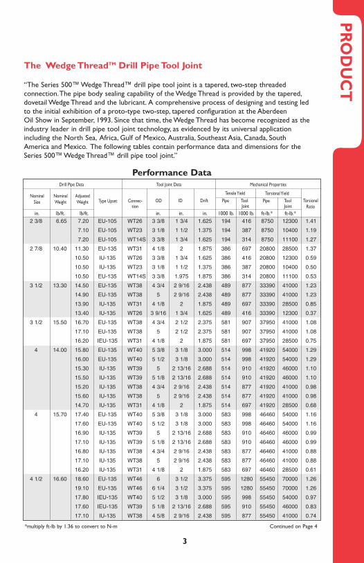
“The Series 500™ Wedge Thread™ drill pipe tool joint is a tapered, two-step threaded connection.The pipe body sealing capability of the Wedge Thread is provided by the tapered,dovetail Wedge Thread and the lubricant. A comprehensive process of designing and testing ledto the initial exhibition of a proto-type two-step, tapered configuration at the Aberdeen Oil Show in September, 1993. Since that time, the Wedge Thread has become recognized as theindustry leader in drill pipe tool joint technology, as evidenced by its universal applicationincluding the North Sea, Africa, Gulf of Mexico, Australia, Southeast Asia, Canada, SouthAmerica and Mexico. The following tables contain performance data and dimensions for theSeries 500™ Wedge Thread™ drill pipe tool joint.”
PR
OD
UC
T
Performance Data
*multiply ft-lb by 1.36 to convert to N-m Continued on Page 4
3 4 3/4 1 3/4 WT26 WT38 4 3/4 2 1/8 WT38 WT264 3/4 1 3/4 WT31 WT38 4 3/4 2 1/8 WT38 WT314 3/4 1 3/4 WT38 WT38
4 15/16 2 1/16 WT38 WT38
3 1/2 5 3/8 2 1/4 WT38 WT40 5 3/8 3 WT40 WT385 3/8 2 1/4 WT39 WT40 5 3/8 3 WT40 WT395 3/8 2 1/4 WT40 WT406 1/8 2 1/4 WT46 WT46
4 1/4 6 5/8 2 13/16 WT40 WT46 6 3 1/2 WT46 WT406 5/8 2 13/16 WT46 WT466 5/8 2 13/16 WT50 WT50
5 1/4 7 3/8 3 1/16 WT40 WT50 6 1/2 3 1/2 WT50 WT407 3/8 3 1/16 WT46 WT50 6 1/2 4 WT50 WT467 3/8 3 1/16 WT50 WT507 3/8 3 1/16 WT54 WT547 3/4 3 1/16 WT56 WT56
8 3 1/16 WT66 WT66
6 10 1/2 5 WT84 WT84
KellyguardSize
On some Kellyguard and Wedge Thread combinations, the desired Wedge Thread size is availableon both valve pin and box. However, on other combinations, the bore on the box end of the one piece valve body prevents using the desired Wedge Thread box. In these cases, a larger sizeWedge Thread with its larger box ID must be used on the box end of the valve. A crossover subis then used on the box end of the valve to cross back to the smaller Wedge Thread size. Forexample, the 3 1/2" Kellyguard is available with a WT40 thread on both pin and box. No crossoveris needed. However, if the 3 1/2" valve is desired with a WT38 connection, the valve is threadedwith a WT38 pin and a WT40 box.A WT40 pin by WT38 box sub is then bucked-on to the boxend of the valve to crossover to the desired WT38 connection.The valve and crossover sub arehandled as a unit.When it is necessary to replace the internal components of the valve, the subis bucked-off and repairs made.
Kellyguard and Wedge Thread Tool Joint OptionsValve Crossover
Kellyguard™ Valve Information
Hydril’s Kellyguard is a manually operated ball valve used to close the bore of the drill string toflow. Hydril designed and developed the one piece Kellyguard to serve the full range of kellyvalve applications: upper kelly cock, top drive kelly cock, lower kelly cock, drill pipe safety valve,and mud saver.The compact, one piece assembly offers high pressure sealing, high tensionstrength, high torsional strength, and durability.
inches inches inches inchesPinOD Ball ID Box OD ID Pin Box
Wedge Thread Field Handbook
4 25
NominalSize
Drill Pipe Data Tool Joint Data Mechanical Properties
NominalWeight
AdjustedWeight Type Upset Connec-
tionOD ID Drift Tool
JointToolJoint
TorsionalRatio
in. lb/ft. lb/ft. in. in. in. 1000 lb. 1000 lb. ft-lb.* ft-lb.*
4 1/2 20.00 22.00 EU-135 WT46 6 3 1/2 3.375 742 1280 66420 70000 1.05
22.50 EU-135 WT46 6 1/4 3 1/2 3.375 742 1280 66420 70000 1.05
21.50 IEU-135 WT40 5 1/2 3 1/8 3.000 742 998 66420 54000 0.81
21.30 IEU-135 WT39 5 1/8 2 13/16 2.688 742 910 66420 46000 0.69
20.80 IU-135 WT38 4 5/8 2 9/16 2.438 742 877 66420 41000 0.62
5 19.50 22.70 EU-135 WT50 6 3/4 4 3.875 712 1440 74100 109000 1.47
23.30 EU-135 WT50 7 4 3.875 712 1440 74100 109000 1.47
22.20 IEU-135 WT50 6 5/8 3 7/8 3.750 712 1533 74100 109000 1.47
21.40 IEU-135 WT46 6 3 1/2 3.375 712 1280 74100 70000 0.94
20.80 IEU-135 WT40 5 3/8 3 1/8 3.000 712 998 74100 54000 0.73
20.80 IEU-135 WT39 5 1/8 2 13/16 2.688 712 910 74100 46000 0.62
5 25.60 28.50 EU-135 WT50 6 3/4 3 7/8 3.750 954 1533 94060 109000 1.16
29.10 EU-135 WT50 7 3 7/8 3.750 954 1533 94060 109000 1.16
28.20 IEU-135 WT50 6 5/8 3 5/8 3.500 954 1710 94060 109000 1.16
27.00 IEU-135 WT46 6 3 1/2 3.375 954 1280 94060 70000 0.74
26.40 IEU-135 WT40 5 3/8 3 1/8 3.000 954 998 94060 54000 0.57
26.40 IEU-135 WT39 5 1/8 2 13/16 2.688 954 910 94060 46000 0.49
5 1/2 21.90 24.20 EU-135 WT56 7 4 5/8 4.500 787 1473 91280 132000 1.45
24.70 EU-135 WT56 7 1/4 4 5/8 4.500 787 1473 91280 132000 1.45
24.30 IEU-135 WT56 7 4 3/8 4.250 787 1685 91280 132000 1.45
24.90 IEU-135 WT56 7 1/4 4 3/8 4.250 787 1685 91280 132000 1.45
24.30 IEU-135 WT54 7 4 3/8 4.250 787 1406 91280 120000 1.31
24.40 IEU-135 WT50 6 3/4 4 3.875 787 1440 91280 109000 1.19
25.00 IEU-135 WT50 7 4 3.875 787 1440 91280 109000 1.19
23.40 IEU-135 WT46 5 7/8 3 1/2 3.375 787 1280 91280 70000 0.77
5 1/2 24.70 26.60 EU-135 WT56 7 4 5/8 4.500 895 1473 101830 132000 1.30
27.20 EU-135 WT56 7 1/4 4 5/8 4.500 895 1473 101830 132000 1.30
26.70 IEU-135 WT56 7 4 3/8 4.250 895 1685 101830 132000 1.30
27.30 IEU-135 WT56 7 1/4 4 3/8 4.250 895 1685 101830 132000 1.30
26.70 IEU-135 WT54 7 4 3/8 4.250 895 1406 101830 120000 1.18
26.90 IEU-135 WT50 6 3/4 4 3.875 895 1440 101830 109000 1.07
27.40 IEU-135 WT50 7 4 3.875 895 1440 101830 109000 1.07
25.80 IEU-135 WT46 5 7/8 3 1/2 3.375 895 1280 101830 70000 0.69
5 7/8 23.40 25.90 IU-135 WT54 7 4 3/8 4.250 844 1406 105490 120000 1.14
25.50 IU-135 WT56 7 4 5/8 4.500 844 1473 105490 132000 1.25
5 7/8 27.00 28.60 IU-135 WT54 7 4 3/8 4.250 961 1406 117920 120000 1.02
28.10 IU-135 WT56 7 4 5/8 4.500 961 1473 117920 132000 1.12
6 5/8 25.20 28.30 IEU-135 WT66 8 5 3/8 5.250 881 1654 127050 168000 1.32
27.00 IEU-135 WT56 7 4 5/8 4.500 881 1473 127050 132000 1.04
6 5/8 27.70 30.10 IEU-135 WT66 8 5 3/8 5.250 962 1654 137330 168000 1.22
28.80 IEU-135 WT56 7 4 5/8 4.500 962 1473 137330 132000 0.96
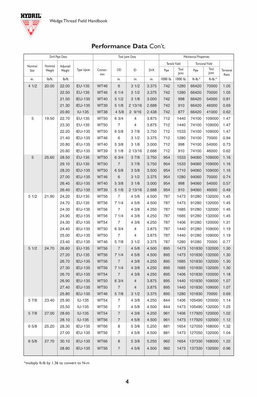
Performance Data Con’t.
*multiply ft-lb by 1.36 to convert to N-m
Minimum Tong Space (see page 11)
The recommended minimum tong space for used API tool joints is provided in API RP 7G,section 12.10.2.e.This same criteria is applied to the Wedge Thread tool joint with the valuesfor the longer Wedge Thread shown in the table below. For the pin, the minimum space is thegreater of either 75% of the tool joint OD or 4". For the box, the minimum space is equal tothe length of the thread plus 1" for non-hardbanded boxes. As stated in RP 7G, the tong spacemay need to be greater for hardbanded joints.
RE
-CU
TT
ING
AN
D
AC
CE
SS
OR
IES
WT14S 3.250 1.975 4.60 0.87
WT23 3.000 1.500 5.94 0.70
WT26 3.250 1.750 5.94 0.70
WT31 4.000 2.000 7.87 0.87
WT38 4.750 2.563 7.87 0.87
WT39 5.000 2.813 7.87 0.87
WT40 5.250 3.125 7.87 0.87
WT46 5.875 3.500 7.87 0.87
WT50 6.500 4.000 8.64 0.99
WT54 6.750 4.375 8.64 0.99
WT56 7.000 4.625 8.64 0.99
WT66 8.000 5.375 8.64 0.99
Minimum Blanking Dimensions and Re-Cut Length Loss
The blanking dimensions for the Hydril Wedge Thread tool joint provide minimum materialdimensions for initial threading. ODs shown provide very little wear allowance and are theminimum diameters that can be threaded.The IDs shown are the maximums that can bethreaded.Tool joint ODs consistent with the tool joints in the rest of the string are recom-mended.The length shown provides no allowance for re-cut.Add the appropriate length for the desired re-cut potential.
Re-cut loss is that length of tong area that will be lost when the wedge thread is re-cut.Existing threads are used during re-cut unless the tool joint has suffered severe damage andthus greater length is required.
Minimum Material Dimensions
Re-Cut Lossin.
Lengthin.
IDin. (+ 0.016)
ODin. (-0.031)
Connection
Torsional YieldTensile Yield
Blanking Dimensions
Pipe Pipe
Converting API to Wedge Thread
The Hydril Wedge Thread tool joint occasionally can be cut over existing API tool joints. TheAPI tool joint ODs must not be smaller and the IDs must not be larger than the values shownin the blanking dimensions table.
PIN (Lpb) 4 4 4 4 4 4 4 1/2 5 1/4 5 1/4 5 1/2 6
BOX (Lb) 5 6 1/4 8 1/4 8 1/4 8 1/4 8 1/4 8 1/4 9 9 9 9
Minimum Recommended Tong Space (inches)
WT14S WT23 WT31 WT38 WT39 WT40 WT46 WT50 WT54 WT56 WT66WT26
Wedge Thread Field Handbook Wedge Thread Field Handbook
24 5
Free Point and Back-Off
When using a free-point and string shot back-off system, the shot size and procedure should bethe same as the shot size and procedure used for a comparable size API tool joint.When a stringshot is used in backing-off operations, swelling of the connection may occur.To determine theextent of this swelling in the pin, make-up a good box with the pin retrieved from the well. If agood box will make-up onto this pin with little resistance and with no unusual standoff, that pin isgood and can continue to be used. In addition, minimal swelling of the box downhole may beassumed. If a good box will not make-up with the pin without excessive standoff, the pin retrievedis oversize and should be set aside for re-cutting. Continued use of an oversize pin could cause agood mating box to split.
Upon retrieving the backed-off box, if the box is not rejected for fishing tool damage, the boxcounterbore diameter should be inspected for swelling using the criteria covered in Inspection.A swollen box should be set aside for re-cutting.
In some instances, a string shot will be set off across a tool joint without backing off the string atthat location.The location in the drill string that the string shot was made should be noted so thetool joint exposed to the shot can be inspected immediately upon recovery.A tool joint that hasbeen exposed to an excessively large shot charge can cause swelling in the tool joint without anyobvious indication of damage. Continued used of a swollen box can result in a parted string dueto inadequate thread engagement. Continued use of an oversize pin could cause a good matingbox to split.
Tool
Join
t Sizeand
Style
Drill Pipe Tool Joint
Nominal Weight Grades
OD of Pin and
BoxID of Pin Bevel
Diameter
Lengthof ToolJointPin
PinTongSpace
BoxTongSpace
Comb.Lengthof PinandBox
Diameter of Box
at elevatorUpset Max.
Make-UpTorques
Min. Max
lb/ft. in. in. in. Lp Lpb Lb L Dte ft-lb.* ft-lb.*
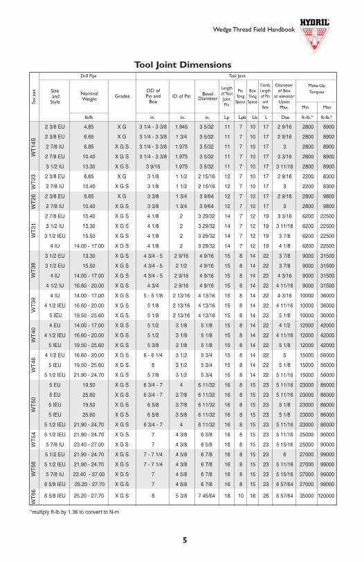
Tool Joint Dimensions
*multiply ft-lb by 1.36 to convert to N-m
2 3/8 EU 4.85 X G 3 1/4 - 3 3/8 1.945 3 5/32 11 7 10 17 2 9/16 2800 8900
2 3/8 EU 6.65 X G 3 1/4 - 3 3/8 1 3/4 3 5/32 11 7 10 17 2 9/16 2800 8900
2 7/8 IU 6.85 X G S 3 1/4 - 3 3/8 1.975 3 5/32 11 7 10 17 3 2800 8900
2 7/8 EU 10.40 X G S 3 1/4 - 3 3/8 1.975 3 5/32 11 7 10 17 3 3/16 2800 8900
3 1/2 IU 13.30 X G S 3 9/16 1.975 3 5/32 11 7 10 17 3 11/16 2800 8900
2 3/8 EU 6.65 X G 3 1/8 1 1/2 2 15/16 12 7 10 17 2 9/16 2200 8300
2 7/8 IU 10.40 X G S 3 1/8 1 1/2 2 15/16 12 7 10 17 3 2200 8300
2 3/8 EU 6.65 X G 3 3/8 1 3/4 3 9/64 12 7 10 17 2 9/16 2800 9800
2 7/8 IU 10.40 X G S 3 3/8 1 3/4 3 9/64 12 7 10 17 3 2800 9800
2 7/8 EU 10.40 X G S 4 1/8 2 3 29/32 14 7 12 19 3 3/16 6200 22500
3 1/2 IU 13.30 X G S 4 1/8 2 3 29/32 14 7 12 19 3 11/16 6200 22500
3 1/2 IEU 15.50 X G S 4 1/8 2 3 29/32 14 7 12 19 3 7/8 6200 22500
4 IU 14.00 - 17.00 X G S 4 1/8 2 3 29/32 14 7 12 19 4 1/8 6200 22500
3 1/2 EU 13.30 X G S 4 3/4 - 5 2 9/16 4 9/16 15 8 14 22 3 7/8 9000 31500
3 1/2 EU 15.50 X G S 4 3/4 - 5 2 1/2 4 9/16 15 8 14 22 3 7/8 9000 31500
4 IU 14.00 - 17.00 X G S 4 3/4 - 5 2 9/16 4 9/16 15 8 14 22 4 3/16 9000 31500
4 1/2 IU 16.60 - 20.00 X G S 4 3/4 2 9/16 4 9/16 15 8 14 22 4 11/16 9000 31500
4 IU 14.00 - 17.00 X G S 5 - 5 1/8 2 13/16 4 13/16 15 8 14 22 4 3/16 10000 36000
4 1/2 IEU 16.60 - 20.00 X G S 5 1/8 2 13/16 4 13/16 15 8 14 22 4 11/16 10000 36000
5 IEU 19.50 - 25.60 X G S 5 1/8 2 13/16 4 13/16 15 8 14 22 5 1/8 10000 36000
4 EU 14.00 - 17.00 X G S 5 1/2 3 1/8 5 1/8 15 8 14 22 4 1/2 12000 42000
4 1/2 IEU 16.60 - 20.00 X G S 5 1/2 3 1/8 5 1/8 15 8 14 22 4 11/16 12000 42000
5 IEU 19.50 - 25.60 X G S 5 3/8 3 1/8 5 1/8 15 8 14 22 5 1/8 12000 42000
4 1/2 EU 16.60 - 20.00 X G S 6 - 6 1/4 3 1/2 5 3/4 15 8 14 22 5 15000 56000
5 IEU 19.50 - 25.60 X G S 6 3 1/2 5 3/4 15 8 14 22 5 1/8 15000 56000
5 1/2 IEU 21.90 - 24.70 X G S 5 7/8 3 1/2 5 3/4 15 8 14 22 5 11/16 15000 56000
5 EU 19.50 X G S 6 3/4 - 7 4 6 11/32 16 8 15 23 5 11/16 23000 86000
5 EU 25.60 X G S 6 3/4 - 7 3 7/8 6 11/32 16 8 15 23 5 11/16 23000 86000
5 IEU 19.50 X G S 6 5/8 3 7/8 6 11/32 16 8 15 23 5 1/8 23000 86000
5 IEU 25.60 X G S 6 5/8 3 5/8 6 11/32 16 8 15 23 5 1/8 23000 86000
5 1/2 IEU 21.90 - 24.70 X G S 6 3/4 - 7 4 6 11/32 16 8 15 23 5 11/16 23000 86000
5 1/2 IEU 21.90 - 24.70 X G S 7 4 3/8 6 5/8 16 8 15 23 5 11/16 25000 90000
5 7/8 IU 23.40 - 27.00 X G S 7 4 3/8 6 5/8 16 8 15 23 5 15/16 25000 90000
5 1/2 EU 21.90 - 24.70 X G S 7 - 7 1/4 4 5/8 6 7/8 16 8 15 23 6 27000 99000
5 1/2 IEU 21.90 - 24.70 X G S 7 - 7 1/4 4 3/8 6 7/8 16 8 15 23 5 11/16 27000 99000
5 7/8 IU 23.40 - 27.00 X G S 7 4 5/8 6 7/8 16 8 15 23 5 15/16 27000 99000
6 5/8 IEU 25.20 - 27.70 X G S 7 4 5/8 6 7/8 16 8 15 23 6 57/64 27000 99000
6 5/8 IEU 25.20 - 27.70 X G S 8 5 3/8 7 45/64 18 10 16 26 6 57/64 35000 120000
WT
23
WT
14S
WT
31W
T38
WT
39W
T40
WT
46W
T50
WT
54W
T56
WT
66W
T26
Wedge Thread Field Handbook Wedge Thread Field Handbook
6 23
MIN
IMU
M Y
IELD
ST
REN
GT
H,K
SI
7595
100
105
115
120
135
MIN
IMU
M T
ENSI
LE S
TR
ENG
TH
,KSI
9510
511
012
012
513
014
5
GR
AD
E
EX
-95
100
G-1
0511
512
0S-
135
2.37
54.
854.
440.
190
1.30
4A
CO
LLA
PS
E P
RE
SS
UR
E11
040
1398
014
720
1546
016
730
1731
019
030
1.99
5ID
BO
DY
YIE
LD S
TR
EN
GT
H98
124
130
137
150
156
176
1.87
0D
DA
PI
INT
ER
NA
L P
RE
SS
UR
E10
500
1330
014
000
1470
016
100
1680
018
900
SD
YIE
LD T
OR
QU
E47
6060
3063
5066
7073
0076
2085
70
2.37
56.
656.
270.
280
1.84
3A
CO
LLA
PS
E P
RE
SS
UR
E15
600
1976
020
800
2184
023
920
2496
028
080
1.81
5ID
BO
DY
YIE
LD S
TR
EN
GT
H13
817
518
419
421
222
124
91.
690
DD
AP
I IN
TE
RN
AL
PR
ES
SU
RE
1547
019
600
2063
021
660
2373
024
760
2785
0S
DY
IELD
TO
RQ
UE
6250
7920
8330
8750
9580
1000
011
250
2.87
56.
856.
170.
217
1.81
2A
CO
LLA
PS
E P
RE
SS
UR
E10
740
1294
013
490
1402
015
070
1556
017
030
2.44
1ID
BO
DY
YIE
LD S
TR
EN
GT
H13
617
218
119
020
821
724
52.
316
DD
AP
I IN
TE
RN
AL
PR
ES
SU
RE
9910
1255
013
210
1387
015
190
1585
017
830
SD
YIE
LD T
OR
QU
E80
8010
240
1078
011
320
1239
012
930
1455
0
Min
imum
Yie
ld -
100
0’s
of P
SI S
tren
gth
Min
imum
Ten
sile
(U
LT)
- 10
00’s
of P
SI S
tren
gth
Dri
ll P
ipe
Bo
dy D
ata
DIA
WN
UW
NW
PEW
ALL
NO
MIN
AL
OD
(IN
)N
OM
INA
LW
EIG
HT
UPS
ET(L
BS/F
T)
NO
MIN
AL
WEI
GH
TN
ON
-UPS
ET(L
BS/F
T)
PLA
IN E
ND
WEI
GH
T/F
T(L
BS/F
T)
WA
LL T
HIC
KN
ESS
(IN)
A -
AR
EA (
IN2 )
ID -
NO
MIN
AL
ID (
IN)
DD
- D
RIF
T D
IAM
ETER
(IN
)
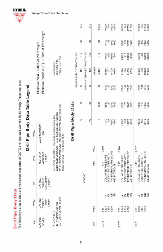
CO
LLA
PSE
PRES
SUR
E -
Pipe
Bod
y C
olla
pse
Rat
ing
(psi
)BO
DY
YIE
LD S
TR
ENG
TH
- A
xial
Yie
ld C
apac
ity (
1000
lbs)
API
INT
ERN
AL
PRES
SUR
E -
Pipe
Bod
y M
in W
all B
urst
Rat
ing
(psi
)Y
IELD
TO
RQ
UE
- Yie
ld T
orqu
e (ft
-lbs)
Con
vers
ions
:ps
i x 6
890
= P
aft
-lbs
x 1.
36 =
N-m
Dri
ll P
ipe
Bo
dy D
ata
The
follo
win
g is
a lis
t of s
izes
and
mec
hani
cal p
rope
rtie
s of
OC
TG d
rill p
ipe
used
with
the
Hyd
ril W
edge
Thr
ead
tool
join
t
Dri
ll P
ipe
Bo
dy D
ata
Tabl
e L
egen
d
DIA
WN
UW
PEW
ALL
WEI
GH
T
Characteristic Break-Out Torques
Hydril Wedge Thread tool joints generally have break-out torques approximately equal to themake-up torques.When downhole make-up occurs, the break-out torque will be higher than themake-up torque. During extended reach drilling operations, downhole make-up is not uncommonand break-out torques can become very large.
Lift-Out
During break-out of the Hydril Wedge Thread tool joint, the negative load flank of the thread canbecome hooked on the box.The pin will lift out of the box more smoothly and possibly avoidthread damage if a lift-out, or de-stabbing, guide is used.After spin-out the lift-out guide is placedstraddling pin and box.As the pin is lifted out of the box, the guide maintains centering betweenpin and box permitting trouble-free lift-out.
The pin will also lift out of the box more smoothly if the pipe is still rotating slightly to the left asthe pin is hoisted. If that is not practical, rotate the pin a half turn past the drop back positionprior to lift out. Rotating the box to the right (drilling direction), as with a rotary table, while lift-ing the pin end out will serve the same purpose.
Left Rotation of Pin with Lift-Out Right Rotation of Box with Lift-Out
Wedge Thread Field Handbook
22
Top Drive Make-Up
When making-up the top drive to a drill pipe tool joint box, maintain top drive spin mode whileslowly lowering the top drive. Upon tagging up, continue slacking-off to allow thread engagement.Maintaining rotation of the top drive while lowering it into the box will reduce stabbing damage.
Back-Up Tong Distance From Face
The Wedge Thread box tong length provides about the same unthreaded length as available on APItool joints.The box tong length on the Wedge Thread tool joint is greater than that for API inorder to both accommodate the longer box and provide adequate gripping length without theneed to get over the thinnest section of the box. Hydril’s recommendation for gripping the box isto be no closer to the face of the box than shown in the table below:
7
2.87
510
.40
9.72
0.36
22.
858
AC
OLL
AP
SE
PR
ES
SU
RE
1651
020
910
2201
023
110
2531
026
410
2972
02.
151
IDB
OD
Y Y
IELD
ST
RE
NG
TH
214
272
286
300
329
343
386
2.02
6D
DA
PI
INT
ER
NA
L P
RE
SS
UR
E16
530
2093
022
030
2314
025
340
2644
029
750
SD
YIE
LD T
OR
QU
E11
550
1464
015
410
1618
017
720
1849
020
800
3.50
013
.30
12.3
20.
368
3.62
1A
CO
LLA
PS
E P
RE
SS
UR
E14
110
1788
018
820
1976
021
640
2258
025
400
2.76
4ID
BO
DY
YIE
LD S
TR
EN
GT
H27
234
436
238
041
643
548
92.
639
DD
AP
I IN
TE
RN
AL
PR
ES
SU
RE
1380
017
480
1840
019
320
2116
022
080
2484
0S
DY
IELD
TO
RQ
UE
1855
023
500
2474
025
970
2845
029
680
3339
0
3.50
015
.50
14.6
40.
449
4.30
4A
CO
LLA
PS
E P
RE
SS
UR
E16
770
2125
022
370
2348
025
720
2684
030
190
2.60
2ID
BO
DY
YIE
LD S
TR
EN
GT
H32
340
943
045
249
551
658
12.
477
DD
AP
I IN
TE
RN
AL
PR
ES
SU
RE
1684
021
330
2245
023
570
2582
026
940
3031
0S
DY
IELD
TO
RQ
UE
2109
026
710
2811
029
520
3233
033
740
3795
0
4.00
014
.00
12.9
50.
330
3.80
5A
CO
LLA
PS
E P
RE
SS
UR
E11
350
1438
015
140
1590
017
410
1817
020
140
3.34
0ID
BO
DY
YIE
LD S
TR
EN
GT
H28
536
138
140
043
845
751
43.
215
DD
AP
I IN
TE
RN
AL
PR
ES
SU
RE
1083
013
720
1444
015
160
1660
017
330
1949
0S
DY
IELD
TO
RQ
UE
2329
029
500
3105
032
600
3571
037
260
4192
0
4.00
015
.70
14.7
10.
380
4.32
2A
CO
LLA
PS
E P
RE
SS
UR
E12
900
1634
017
200
1805
019
770
2063
023
210
3.24
0ID
BO
DY
YIE
LD S
TR
EN
GT
H32
441
143
245
449
751
958
33.
115
DD
AP
I IN
TE
RN
AL
PR
ES
SU
RE
1247
015
790
1663
017
460
1912
019
950
2244
0S
DY
IELD
TO
RQ
UE
2581
032
690
3441
036
130
3958
041
300
4646
0
4.00
017
.00
15.9
00.
415
4.67
4A
CO
LLA
PS
E P
RE
SS
UR
E13
950
1767
018
600
1953
021
390
2232
025
110
3.17
0ID
BO
DY
YIE
LD S
TR
EN
GT
H35
144
446
749
153
856
163
13.
045
DD
AP
I IN
TE
RN
AL
PR
ES
SU
RE
1362
017
250
1816
019
060
2088
021
790
2451
0S
DY
IELD
TO
RQ
UE
2744
034
760
3659
038
420
4208
043
910
4940
0
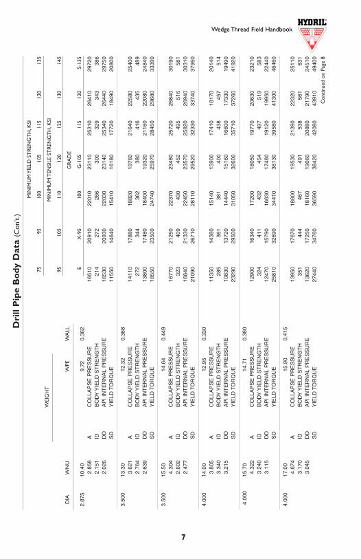
Dri
ll P
ipe
Bo
dy D
ata
(Con
’t.)
Con
tinue
d on
Pag
e 8
MIN
IMU
M Y
IELD
ST
REN
GT
H,K
SI
7595
100
105
115
120
135
MIN
IMU
M T
ENSI
LE S
TR
ENG
TH
,KSI
9510
511
012
012
513
014
5
GR
AD
E
EX
-95
100
G-1
0511
512
0S-
135
DIA
WN
UW
PEW
ALL
WEI
GH
T
Wedge Thread Field Handbook
WT14S 1"WT23 1''WT26 1''WT31 2''WT38 2''WT39 2''WT40 2''WT46 2''WT50 2''WT54 2''WT56 2''WT66 2''
Minimum LengthFrom Box Face
These distances will be adequate to prevent crushing of the box. However, since the connectioncan tolerate considerable OD wear without loss of torque strength and there is a very broadrange for make-up torque, use of worn OD strings at very high make-up torques may requireadjustment.
Alignment and Standing Back
The Hydril Wedge Thread tool joint is a two-step connection, which allows deep stabbing onmake-up. However, even with this advantage, proper alignment of the pipe in the stand with thebox in the floor is crucial. Excessive make-up speed could be damaging and should be avoided.Ocean currents as well as windy weather can impair proper alignment and drilling crews need touse extra care when working in these conditions. Hydril’s rugged tool joints are designed asthread sealing connections, making them less susceptible to damage during the standing backprocess.
Elevators
Hydril tool joints are intended for use with conventional18º bottleneck elevators. The diameter of the box atthe elevator upset (Dte) is the same as that on conven-tional tool joints using API upsets. For those WedgeThread tool joints that are welded on to non-APIupsets, special elevator bores may be needed. In caseswhere the lift area of the tool joint (see diagram) is notsufficient, lifting plugs should be used in conjunctionwith collar type elevators.
Tool Joint OD
Lift Area
ToolJoint
Wedge Thread Field Handbook
8 21
Thread Compound
The Series 500 Wedge Thread drill pipe tool joint creates a seal in the threads rather than onthe external shoulder. Because the threads and lubricant are used to create the seal, selectionand application of the thread compound warrants individual attention.The following proce-dures should be used when running Hydril Wedge Thread tool joints:
• Compounds That Contain Solid Fillers Are Required - These tool joints use a threadlubricant seal system for both internal pressure and external pressure. Solid particles dis-persed in the thread compound provide the fillers necessary to create the seal.
• Arctic Grade Compound Is Recommended During Freezing Weather - Normalcompounds can become stiff at low temperatures, leading to an excessive amount of com-pound applied to the tool joint.A compound that can be applied at low temperatures usinga bristle brush is recommended.
• Application - When picking up the drill pipe for the initial run into the hole, apply an evencoating of thread compound over the entire pin thread.There is no need to dope the box -thread compound will be carried into the box by the pin thread.After the first trip, applycompound sparingly to the pin or re-distribute the existing compound around the pin with-out adding thread compound.A stress reduction groove is located in the root of the largestep of the pin to prevent excess thread compound build up.
Zinc tool joint compounds and copper/graphite tool joint compounds have been used exten-sively on Hydril Wedge Thread tool joints.These compounds will provide proper performancefor the life of the tool joint.
Initial Make-up Procedure (Break-In)
Hydril has not found it necessary to use a standard break-in procedure. Initial break-in of theconnection is performed on the first trip into the hole and should include slowly making upthe pin, with its application of thread compound, to the targeted torque. No make and breakor low torque break-in is required.
Make-Up Torque
The Wedge Thread tool joint has a very broad range of acceptable make-up torques. Manyoperators prefer a make-up torque 10-20% higher than the expected operating torque.Whenthe expected operating torque is relatively low, using a make-up torque at the lower end ofthe range provides several benefits:
1. The lower make-up torques will result in less wear on the make-up equipment, i.e. hydraulictongs, rig tongs, iron roughnecks, etc.
2. A lower make-up torque requires fewer turns to make-up from the hand tight position tothe power tight position.This can reduce the running time.
3. The lower make-up torque will reduce the wear on the tool joint itself, thus extending thelife of the string.
Since additional torque does not produce additional tensile stress in the pin, downhole make-up will not create excessive stress in the tool joint. For this reason, using a lower make-uptorque while tolerating subsequent downhole make-up is recommended.
RUN
NIN
G A
ND
HA
ND
LING
4.50
016
.60
15.0
00.
337
4.40
7A
CO
LLA
PS
E P
RE
SS
UR
E10
390
1276
013
300
1382
014
850
1534
016
770
3.82
6ID
BO
DY
YIE
LD S
TR
EN
GT
H33
141
944
146
350
752
959
53.
701
DD
AP
I IN
TE
RN
AL
PR
ES
SU
RE
9830
1245
013
110
1376
015
070
1573
017
690
SD
YIE
LD T
OR
QU
E30
810
3902
041
080
4313
047
240
4929
055
450
4.50
020
.00
18.7
10.
430
5.49
8A
CO
LLA
PS
E P
RE
SS
UR
E12
960
1642
017
280
1815
019
880
2074
023
330
3.64
0ID
BO
DY
YIE
LD S
TR
EN
GT
H41
252
255
057
763
266
074
23.
515
DD
AP
I IN
TE
RN
AL
PR
ES
SU
RE
1254
015
890
1672
017
560
1923
020
070
2258
0S
DY
IELD
TO
RQ
UE
3690
046
740
4920
051
660
5658
059
040
6642
0
5.00
016
.25
14.8
80.
296
4.37
4A
CO
LLA
PS
E P
RE
SS
UR
E69
4081
1083
7086
2090
8092
8098
304.
408
IDB
OD
Y Y
IELD
ST
RE
NG
TH
328
416
437
459
503
525
590
4.28
3D
DA
PI
INT
ER
NA
L P
RE
SS
UR
E77
7098
4010
360
1088
011
910
1243
013
990
SD
YIE
LD T
OR
QU
E35
040
4439
046
730
4906
053
730
5607
063
080
5.00
019
.50
17.9
50.
362
5.27
5A
CO
LLA
PS
E P
RE
SS
UR
E99
6012
020
1252
013
000
1394
014
380
1567
04.
276
IDB
OD
Y Y
IELD
ST
RE
NG
TH
396
501
528
554
607
633
712
4.15
1D
DA
PI
INT
ER
NA
L P
RE
SS
UR
E95
0012
040
1267
013
300
1457
015
200
1710
0S
DY
IELD
TO
RQ
UE
4117
052
140
5489
057
630
6312
065
870
7410
0
5.00
025
.60
24.0
50.
500
7.06
9A
CO
LLA
PS
E P
RE
SS
UR
E13
500
1710
018
000
1890
020
700
2160
024
300
4.00
0ID
BO
DY
YIE
LD S
TR
EN
GT
H53
067
270
774
281
384
895
43.
875
DD
AP
I IN
TE
RN
AL
PR
ES
SU
RE
1313
016
630
1750
018
380
2013
021
000
2363
0Y
IELD
TO
RQ
UE
5226
066
190
6968
073
160
8013
083
610
9406
0
5.50
019
.20
16.8
90.
304
4.96
2A
CO
LLA
PS
E P
RE
SS
UR
E60
4069
4071
4073
1076
3077
6080
904.
892
IDB
OD
Y Y
IELD
ST
RE
NG
TH
372
471
496
521
571
595
670
4.76
7D
DA
PI
INT
ER
NA
L P
RE
SS
UR
E72
5091
9096
7010
160
1112
011
610
1306
0Y
IELD
TO
RQ
UE
4407
055
830
5877
061
700
6758
070
520
7933
0
Dri
ll P
ipe
Bo
dy D
ata
(Con
’t.)
MIN
IMU
M Y
IELD
ST
REN
GT
H,K
SI
7595
100
105
115
120
135
MIN
IMU
M T
ENSI
LE S
TR
ENG
TH
,KSI
9510
511
012
012
513
014
5
GR
AD
E
EX
-95
100
G-1
0511
512
0S-
135
DIA
WN
UW
PEW
ALL
WEI
GH
T
Wedge Thread Field Handbook Wedge Thread Field Handbook
20 9
After the thread wear indicator contacts the box face, the connection should be re-cut. Inspectorsshould check for:
• deformation on the wear indicator• scoring marks on pin shoulder or box face• burnish patterns on pin shoulder or box face• gap closure
If any of the above indications are found on either the box or the pin end, then that end should bere-cut.
When calculating the string length, the gap between the box and the pin can be incorporated afterthe joints have been made up. New pipe will have a shoulder gap of approximately 3/16" to 1/4"(0.188" to 0.250")
Bevel Diameter
The bevel diameter provides an indication of tool joint OD wear. Hydril’s Wedge Thread tool jointis designed to compensate for OD wear and reduction encountered during drilling applications.The tool joint retains full rated tension and torque strength with OD wear down to the beveldiameter.Allowance must be made for adequate tool joint OD wear to extend the life of the string.
If hard banding is present, a smaller initial tool joint OD may be used. Often, the OD of the hardbanding will be larger (proud) than the tool joint OD. The proud hard banding will absorb thewear during drilling.When the hard banding is reduced to the tool joint OD, the hard bandingshould be rebuilt.With this system, the proud hard banding replaces the wear allowance of largeOD tool joints.
Box OD Swell and Ovality Guidelines
The Series 500 Wedge Thread drill pipe tool joint is a rugged connection and not as susceptible toover-torque or other field damage as conventionaltool joints. However, gross over-torque of the tooljoint or application of an excessive amount ofthread compound can cause swelling of the box. Ifthere is indication of box swelling or out-of-round-ness, it is recommended that box counterbore diam-eters be checked.
There are two locations to be measured, the coun-terbore diameter at the face of the box, D1, and thecounterbore diameter immediately behind the largestep thread, D2. If either has a maximum diameterthat is larger than the maximum acceptable valueshown in the table, the box should be re-cut.
D1D2
5.50
021
.90
19.8
30.
361
5.82
8A
CO
LLA
PS
E P
RE
SS
UR
E84
1010
020
1040
010
750
1145
011
760
1267
04.
778
IDB
OD
Y Y
IELD
ST
RE
NG
TH
437
554
583
612
670
699
787
4.65
3D
DA
PI
INT
ER
NA
L P
RE
SS
UR
E86
1010
910
1149
012
060
1321
013
780
1551
0S
DY
IELD
TO
RQ
UE
5071
064
230
6761
070
990
7776
081
140
9128
0
5.50
024
.70
22.5
60.
415
6.63
0A
CO
LLA
PS
E P
RE
SS
UR
E10
460
1293
013
480
1401
015
060
1556
017
020
4.67
0ID
BO
DY
YIE
LD S
TR
EN
GT
H49
763
066
369
676
279
689
54.
545
DD
AP
I IN
TE
RN
AL
PR
ES
SU
RE
9900
1254
013
200
1386
015
190
1585
017
830
SD
YIE
LD T
OR
QU
E56
570
7166
075
430
7920
0 86
750
9052
010
1830
5.87
523
.40
21.2
80.
361
6.25
4A
CO
LLA
PS
E P
RE
SS
UR
E74
5087
7090
8093
6099
1010
140
1082
05.
153
IDB
OD
Y Y
IELD
ST
RE
NG
TH
469
594
625
657
719
750
844
5.02
8D
DA
PI
INT
ER
NA
L P
RE
SS
UR
E80
6010
220
1075
011
290
1237
012
900
1452
0S
DY
IELD
TO
RQ
UE
5861
074
230
7814
082
050
8986
093
770
1054
90
5.87
527
.00
24.2
20.
415
7.11
9A
CO
LLA
PS
E P
RE
SS
UR
E95
6011
500
1197
012
410
1329
013
700
1489
05.
045
IDB
OD
Y Y
IELD
ST
RE
NG
TH
534
676
712
747
819
854
961
4.92
0D
DA
PI
INT
ER
NA
L P
RE
SS
UR
E92
7011
740
1236
012
980
1422
014
830
1669
0S
DY
IELD
TO
RQ
UE
6551
082
980
8734
091
710
1004
5010
4810
1179
20
6.62
525
.20
22.2
10.
330
6.52
6A
CO
LLA
PS
E P
RE
SS
UR
E47
9053
2054
2055
0056
2057
2060
405.
965
IDB
OD
Y Y
IELD
ST
RE
NG
TH
489
620
653
685
750
783
881
5.84
0D
DA
PI
INT
ER
NA
L P
RE
SS
UR
E65
4082
8087
2091
5010
020
1046
011
770
SD
YIE
LD T
OR
QU
E70
580
8940
094
110
9881
010
8220
11
2930
12
7050
6.62
527
.70
24.2
40.
362
7.12
3A
CO
LLA
PS
E P
RE
SS
UR
E58
9067
5069
4071
0074
0075
2078
105.
901
IDB
OD
Y Y
IELD
ST
RE
NG
TH
534
677
712
748
819
855
962
5.77
6D
DA
PI
INT
ER
NA
L P
RE
SS
UR
E71
7090
8095
6010
040
1100
011
470
1291
0S
DY
IELD
TO
RQ
UE
7630
096
640
1017
30
1068
10
1169
90
1220
7013
7330
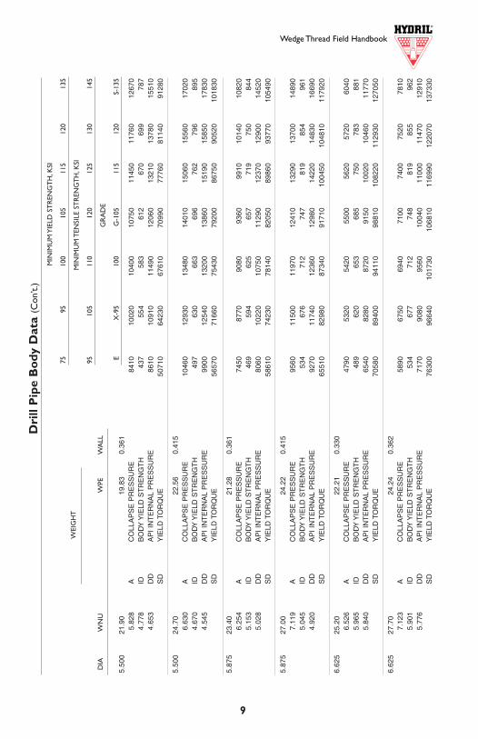
Dri
ll P
ipe
Bo
dy D
ata
(Con
’t.)
MIN
IMU
M Y
IELD
ST
REN
GT
H,K
SI
7595
100
105
115
120
135
MIN
IMU
M T
ENSI
LE S
TR
ENG
TH
,KSI
9510
511
012
012
513
014
5
GR
AD
E
EX
-95
100
G-1
0511
512
0S-
135
DIA
WN
UW
PEW
ALL
WEI
GH
T
WT14S 3.090 Not Applicable
WT23 2.765 2.415
WT26 2.980 2.630
WT31 3.685 3.145
WT38 4.295 3.755
WT39 4.510 3.970
WT40 4.820 4.280
WT46 5.390 4.850
WT50 5.940 5.360
WT54 6.180 5.600
WT56 6.430 5.850
WT66 7.155 6.575
D2 (inches)
Maximum Counterbore Diameter
D1 (inches)
D1 D2
Wedge Thread Field Handbook
10 19
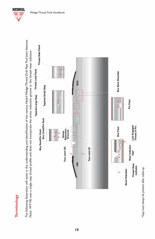
Term
ino
logy
The
follo
win
g ill
ustr
atio
n w
ill a
ssis
t in
the
und
erst
andi
ng a
nd id
entif
icat
ion
of t
he v
ario
us H
ydri
l Wed
ge T
hrea
d D
rill
Pipe
Too
l Joi
nt fe
atur
es.
Not
e:W
T14
S us
es a
sin
gle
step
thr
ead
prof
ile a
nd d
oes
not
inco
rpor
ate
the
stre
ss r
educ
tion
groo
ve o
r th
e th
read
wea
r in
dica
tor.
*Gap
mus
t alw
ays
be p
rese
nt a
fter
mak
e-up
.
Too
lJo
int
OD
PIN
BO
X
Str
ess
Red
uct
ion
Gro
ove
s
Bev
elD
iam
eter
Bo
xF
ace
Pin
Fac
eW
ear
Ind
icat
or
Gap
*L
ast
En
gag
edT
hre
ado
fP
in
Bo
xB
ore
Sh
ou
lder
Bo
xR
oo
t/P
inC
rest
Bo
xC
rest
/Pin
Ro
ot
Tap
ered
Lar
ge
Ste
p
Tap
ered
Sm
allS
tep
Th
read
Lo
adF
lan
k
Th
read
Sta
bF
lan
k
Too
lJo
int
ID
Th
read
Wea
rIn
dic
ato
r
INSP
ECT
ION
Field Inspection (see page 10)
The Series 500 Wedge Thread drill pipe tool joint is a rugged connection and not as suscepti-ble to field damage as most connections. Unlike conventional shouldering tool joints, theWedge Thread creates a seal in the tapered thread of the small step rather than on the exter-nal shoulder. Because the threads create the seal, damage to the pin external shoulder or boxface does not require re-facing or rejection of the joint.Typical running and handling damageto the Wedge Thread can be field repaired. Damage to the pin face, pin external shoulder, boxface, and box internal shoulder can be hand dressed to remove any protrusion that wouldinterfere with make-up of the mating threads. Shoulders should not be re-faced. Repair threadsas needed.The thread surface can be dressed with a file or hand grinder and then wiped clean.The thread flanks, roots, and crests should have a relatively even surface. Inspect threads for:
• Dents and mashed areas. Damage that raises metal above the original surface will inter-fere with full engagement of pin and box and must be removed with a file or hand grinder.
• Excessive galling and scoring. Galling that wipes out threads or that cannot be dressedusing a file or hand grinder will prevent proper thread engagement and is excessive.
• Out-of-roundness that would prevent proper stabbing. A connection that is exceed-ingly out-of-round will not stab deep and will develop torque prematurely.
• Excessive rust or scale. Build-up of corrosion products will prevent proper make-up ofpin and box and should be removed.This can be done with a wire brush. Small pits and otherlocal metal loss corrosion will not interfere with proper make-up or sealing and are notcause for rejection. However, the surface should be free of pits and other surface imperfec-tions that exceed 1/16" in depth and 1/8" in diameter or extend more than 1 1/2” in lengthalong the thread helix.
• Thread protrusions. Any burrs, raised corners, or other damage projecting outward fromthe thread surface should be hand dressed until the surface is even.
The Hydril Wedge Thread tool joint inspection procedure allows drilling crews to determine if the connection warrants repairs. Hydril’s rugged design permits field repairing most of thedamage encountered by the Wedge Thread, a repair procedure that is less expensive and timeconsuming than re-cutting the tool joint.
Shoulder Gap
The Hydril Series 500 Wedge Thread drill pipe tool joint is designed with a wear indicator gapbetween the box face and the external shoulder of the pin.This gap eliminates the reactionsurface found in the torque shoulder of conventional tool joints. However, after repetitive make-up and break-out operations, the thread flanks wear permitting additional travel of the pin intothe box.This leads to a smaller gap at the external shoulder and, eventually, an engagementbetween the face of the box and the thread wear indicator projecting from the pin shoulder.The protruding shape of the thread wear indicator was designed such that it would amplydeform showing adequate signs of a nearly worn out connection.The purpose of the indicatoris to provide an allowance of several make-and-breaks before the connection is fully worn out,and ultimately indicating when the connection should be re-cut.When the connection is fullyworn out, there is full contact between the external pin shoulder and the face of the box.
WT14S 3.375 1.975 2.8 10.1 285 7.3 285
WT23 3.125 1.500 2.2 9.5 352 6.5 352
WT23 3.375 1.500 2.2 9.5 352 6.5 352
WT26 3.375 1.750 2.8 11.2 378 7.7 378
WT31 4.125 2.000 6.1 26 634 19.1 634
WT38 4.750 2.500 9.0 37 825 27 825
WT38 4.750 2.563 9.0 37 797 27 797
WT38 5.000 2.563 9.0 37 797 27 797
WT39 5.000 2.813 10.0 42 827 30 827
WT39 5.125 2.813 10.0 42 827 30 827
WT40 5.375 3.125 12.0 49 907 36 907
WT40 5.500 3.125 12.0 49 907 36 907
WT46 5.875 3.500 15.0 64 1164 44 1164
WT46 6.000 3.500 15.0 64 1164 44 1164
WT46 6.250 3.500 15.0 64 1164 44 1164
WT50 6.625 3.625 23.0 99 1555 70 1555
WT50 7.000 3.875 23.0 99 1394 73 1394
WT50 7.000 4.000 23.0 99 1309 74 1309
WT54 7.000 4.375 25.0 109 1278 83 1278
WT56 7.000 4.375 27.0 119 1532 87 1532
WT56 7.000 4.500 27.0 119 1436 89 1436
WT56 7.000 4.625 27.0 119 1339 91 1339
WT56 7.250 4.625 27.0 119 1339 91 1339
WT66 8.000 5.375 35.0 153 1504 117 1504
Wedge Thread Field Handbook Wedge Thread Field Handbook
18 11
AP
I D
esig
nati
ons
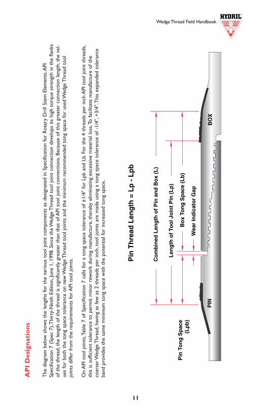
The
dia
gram
bel
ow s
how
s th
e le
ngth
s fo
r th
e va
riou
s to
ol jo
int
com
pone
nts
as d
esig
nate
d in
Spe
cific
atio
n fo
r R
otar
y D
rill
Stem
Ele
men
ts,A
PISp
ecifi
catio
n 7
(Spe
c 7)
,Thi
rty-
Nin
th E
ditio
n,Ju
ne 1
,199
8.Si
nce
the
Wed
ge T
hrea
d to
ol jo
int
conn
ectio
n de
velo
ps it
s hi
gh t
orqu
e st
reng
th in
the
flan
ksof
the
thr
ead,
the
leng
th o
f the
thr
ead
is s
igni
fican
tly g
reat
er t
han
that
of A
PI t
ool j
oint
con
nect
ions
.Bec
ause
of t
his
grea
ter
conn
ectio
n le
ngth
,the
val
-ue
s fo
r bo
th t
he t
ong
spac
e to
lera
nce
on n
ew W
edge
Thr
ead
tool
join
ts a
nd t
he m
inim
um r
ecom
men
ded
tong
spa
ce fo
r us
ed W
edge
Thr
ead
tool
join
ts d
iffer
from
the
req
uire
men
ts fo
r A
PI t
ool j
oint
s.
On
API
too
l joi
nts,
Tabl
e 7
of S
peci
ficat
ion
7 ca
lls fo
r a
tong
spa
ce t
oler
ance
of ±
1/4"
for
Lpb
and
Lb.F
or t
he 4
thr
eads
per
inch
API
too
l joi
nt t
hrea
ds,
this
is s
uffic
ient
tol
eran
ce t
o pe
rmit
min
or r
ewor
k du
ring
man
ufac
ture
,the
reby
elim
inat
ing
exce
ssiv
e m
ater
ial l
oss.
To fa
cilit
ate
man
ufac
ture
of t
heco
arse
r Wed
ge T
hrea
d,ha
ving
as
few
as
2 th
read
s pe
r in
ch,t
ool j
oint
s ar
e m
ade
usin
g a
tong
spa
ce t
oler
ance
of -
1/4"
,+3/
4".T
his
expa
nded
tol
eran
ceba
nd p
rovi
des
the
sam
e m
inim
um t
ong
spac
e w
ith t
he p
oten
tial f
or in
crea
sed
tong
spa
ce.
Tension Vs. Make-Up Torque For Wedge Thread Tool Joint
Tension Versus Make-Up TorqueA B C D
Minimum Yield TensileTorque Torque/1.1 Yield/1.1 Torque Tension
Make-Up Torque
C D
BA
Tens
ion
Tool Joint
Inches Inches 1000 lbs.1000 ft-lbs.1000 lbs.1000 ft-lbs.1000 ft-lbs.
Size IDOD
Transition Point
Wedge Thread Field Handbook
12
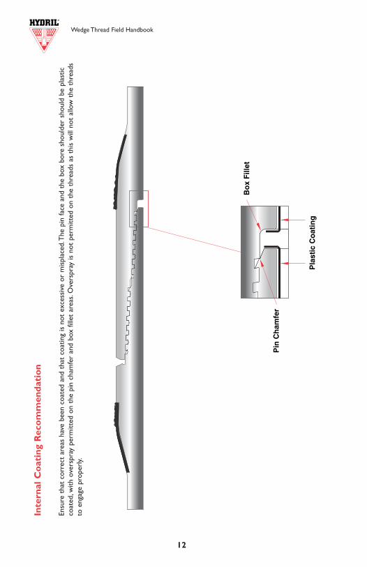
Inte
rnal
Co
atin
g R
eco
mm
enda
tio
n
Ensu
re t
hat
corr
ect
area
s ha
ve b
een
coat
ed a
nd t
hat
coat
ing
is n
ot e
xces
sive
or
mis
plac
ed.T
he p
in fa
ce a
nd t
he b
ox b
ore
shou
lder
sho
uld
be p
last
icco
ated
,with
ove
rspr
ay p
erm
itted
on
the
pin
cham
fer
and
box
fille
t ar
eas.
Ove
rspr
ay is
not
per
mitt
ed o
n th
e th
read
s as
thi
s w
ill n
ot a
llow
the
thr
eads
to e
ngag
e pr
oper
ly.
Wedge Thread Field Handbook
WT
40
17
8.000 8.125 8.250 8.375 8.500 8.625 8.750 8.875 9.0003.000 1.09 1.18 1.27 1.37 1.46 1.56 1.66 1.76 1.873.500 1.13 1.22 1.32 1.42 1.51 1.62 1.72 1.83 1.934.000 1.20 1.29 1.39 1.49 1.60 1.70 1.81 1.93 2.044.500 1.30 1.41 1.51 1.62 1.74 1.85 1.97 2.10 2.224.750 1.38 1.49 1.60 1.72 1.84 1.97 2.09 2.22 2.355.000 1.48 1.60 1.73 1.85 1.98 2.11 2.25 2.39 2.535.250 1.62 1.76 1.89 2.03 2.17 2.32 2.47 2.62 2.775.375 1.72 1.86 2.00 2.14 2.29 2.45 2.60 2.77 2.93
5.250 5.375 5.500 5.625 5.750 5.875 6.000 6.1252.000 1.16 1.29 1.43 1.57 1.71 1.87 2.02 2.192.250 1.19 1.32 1.46 1.61 1.76 1.91 2.07 2.242.500 1.23 1.37 1.52 1.66 1.82 1.98 2.15 2.322.813 1.32 1.46 1.62 1.77 1.94 2.11 2.29 2.483.000 1.39 1.54 1.70 1.87 2.05 2.23 2.42 2.613.125 1.45 1.61 1.78 1.96 2.14 2.33 2.52 2.73
7.000 7.125 7.250 7.375 7.500 7.625 7.750 7.875 8.0003.000 1.04 1.14 1.24 1.34 1.45 1.56 1.67 1.79 1.903.250 1.06 1.16 1.27 1.37 1.48 1.59 1.71 1.83 1.953.500 1.10 1.20 1.31 1.42 1.53 1.64 1.76 1.89 2.013.750 1.14 1.25 1.36 1.47 1.59 1.71 1.84 1.96 2.094.000 1.20 1.31 1.43 1.55 1.67 1.80 1.93 2.06 2.204.250 1.28 1.40 1.53 1.65 1.79 1.92 2.06 2.20 2.354.500 1.39 1.52 1.66 1.80 1.94 2.09 2.24 2.39 2.554.625 1.46 1.60 1.74 1.89 2.04 2.20 2.35 2.52 2.69
WT
46
5.875 6.000 6.125 6.250 6.375 6.500 6.625 6.7502.250 1.09 1.21 1.32 1.45 1.57 1.71 1.84 1.982.500 1.11 1.23 1.35 1.48 1.61 1.74 1.88 2.032.813 1.16 1.28 1.41 1.54 1.67 1.81 1.95 2.103.000 1.19 1.32 1.45 1.58 1.72 1.87 2.02 2.173.250 1.26 1.39 1.53 1.67 1.82 1.97 2.13 2.293.500 1.35 1.49 1.64 1.79 1.95 2.11 2.28 2.46
WT
50
6.500 6.625 6.750 6.875 7.000 7.125 7.250 7.3752.500 1.09 1.20 1.31 1.42 1.54 1.66 1.78 1.912.813 1.12 1.23 1.34 1.46 1.58 1.70 1.83 1.963.000 1.14 1.26 1.37 1.49 1.61 1.73 1.86 2.003.250 1.18 1.30 1.42 1.54 1.67 1.79 1.93 2.073.500 1.24 1.36 1.48 1.61 1.74 1.88 2.02 2.163.750 1.31 1.44 1.57 1.71 1.85 1.99 2.14 2.294.000 1.42 1.56 1.70 1.85 2.00 2.15 2.31 2.48
WT
54
6.750 6.875 7.000 7.125 7.250 7.375 7.500 7.6253.000 1.09 1.19 1.30 1.41 1.52 1.64 1.76 1.883.250 1.12 1.22 1.33 1.45 1.56 1.68 1.81 1.933.500 1.16 1.27 1.38 1.50 1.62 1.75 1.88 2.013.750 1.22 1.33 1.45 1.58 1.70 1.83 1.97 2.114.000 1.29 1.42 1.55 1.68 1.81 1.95 2.09 2.244.250 1.40 1.54 1.67 1.82 1.96 2.11 2.27 2.434.375 1.47 1.61 1.76 1.91 2.06 2.22 2.38 2.55
WT
56W
T66
OD (inches)
OD (inches)
OD (inches)
OD (inches)
OD (inches)
OD (inches)
ID(inches)
ID(inches)
ID(inches)
ID(inches)
ID(inches)
ID(inches)
Wedge Thread Field Handbook Wedge Thread Field Handbook
16 13
Bending Strength Ratios
The bending strength ratios (BSR) of the Wedge Thread tool joints will generally be less than those of comparable number API tool joints. Since the Wedge Thread “shoulder” mechanism is different from the conventional shoulder system of API tool joints, these lower BSR values are appropriate for the Wedge Thread tool joints. Hydril recommends BSR between 1.0 and 1.5 for the Wedge Thread tool joint to maximize fatigue strength when using the Wedge Thread tool joint on drill collars.The API indicates a BSR of 2.50 is desired and between 1.90 and 3.20 may be acceptable for API tool joints. In the conventional shouldering connection, the pin critical section is pre-loaded at make-up. During bending, this pre-loadreduces the amplitude of the cycling stress in the pin critical section.The box in this system does not benefit from a reduced stress amplitude, so it is subjected to a greater stress range than the pin. Making the bending strength of the box greater than that of the pin produces a balanced connection for the conventional shouldering tool joints. In the Wedge Thread “shouldering” system, neither pin nor box use a conventional shoulder. Since the pin and the box will not have this dissimilar stress range,the API BSR values would not be applicable.
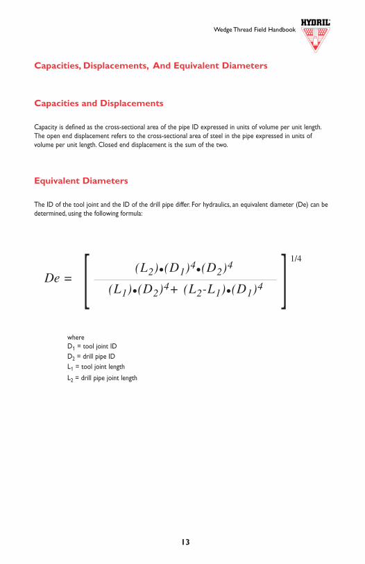
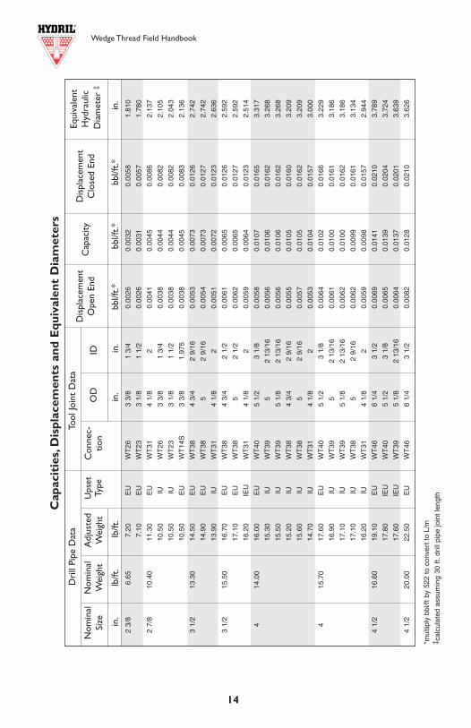
Capacities, Displacements, And Equivalent Diameters
Capacities and Displacements
Capacity is defined as the cross-sectional area of the pipe ID expressed in units of volume per unit length.The open end displacement refers to the cross-sectional area of steel in the pipe expressed in units of volume per unit length. Closed end displacement is the sum of the two.
Equivalent Diameters
The ID of the tool joint and the ID of the drill pipe differ. For hydraulics, an equivalent diameter (De) can bedetermined, using the following formula:
whereD1 = tool joint IDD2 = drill pipe IDL1 = tool joint length
L2 = drill pipe joint length
(L1)•(D2)4+ (L2-L1)•(D1)4 ][ (L2)•(D1)4•(D2)4De =
1/4
3.250 3.375 3.500 3.625 3.750 3.875 4.0001.250 1.27 1.49 1.74 1.99 2.27 2.56 2.861.500 1.33 1.57 1.82 2.09 2.38 2.69 3.011.750 1.45 1.71 1.99 2.29 2.60 2.93 3.29
3.250 3.375 3.500 3.625 3.7501.500 0.89 1.13 1.38 1.63 1.911.750 0.97 1.22 1.49 1.77 2.071.975 1.09 1.37 1.67 1.99 2.32
BSR for Drill Collars
4.000 4.125 4.250 4.375 4.500 4.625 4.7501.500 1.35 1.53 1.72 1.91 2.12 2.33 2.561.750 1.40 1.58 1.78 1.98 2.19 2.42 2.652.000 1.48 1.67 1.88 2.09 2.32 2.55 2.80
4.750 4.875 5.000 5.125 5.250 5.375 5.500 5.6251.500 1.31 1.45 1.61 1.77 1.94 2.12 2.30 2.501.750 1.33 1.48 1.64 1.80 1.98 2.16 2.34 2.542.000 1.37 1.52 1.68 1.85 2.03 2.22 2.41 2.612.250 1.42 1.58 1.75 1.93 2.12 2.31 2.51 2.722.500 1.51 1.68 1.86 2.05 2.25 2.45 2.67 2.892.563 1.54 1.71 1.90 2.09 2.29 2.50 2.72 2.94
WT
14S
WT
26W
T3 1
WT
38
ID(inches)
ID(inches)
ID(inches)
ID(inches)
OD (inches)
OD (inches)
OD (inches)
OD (inches)
5.000 5.125 5.250 5.375 5.500 5.625 5.750 5.8752.000 1.35 1.49 1.65 1.81 1.97 2.15 2.33 2.522.250 1.39 1.54 1.70 1.87 2.04 2.22 2.41 2.602.500 1.46 1.62 1.79 1.96 2.14 2.33 2.53 2.732.813 1.60 1.77 1.96 2.15 2.35 2.55 2.77 2.99
WT
39
ID(inches)
OD (inches)
3.000 3.125 3.250 3.375 3.5001.000 1.27 1.51 1.76 2.04 2.331.250 1.31 1.56 1.83 2.12 2.421.500 1.41 1.68 1.96 2.27 2.60
WT
23
ID(inches)
OD (inches)
Dri
ll Pi
pe D
ata
Too
l Joi
nt D
ata
in.
lb/ft
.lb
/ft.
in.
in.
bbl/f
t.*
bb
l/ft.*
bbl
/ft.*
in.
4 1/
220
.00
21.5
0IE
UW
T40
5 1/
23
1/8
0.00
780.
0126
0.02
043.
573
21.3
0IE
UW
T39
5 1/
82
13/1
60.
0077
0.01
250.
0202
3.50
3
519
.50
23.3
0E
UW
T50
74
0.00
850.
0176
0.02
614.
245
22.2
0IE
UW
T50
6 5/
83
7/8
0.00
810.
0175
0.02
564.
228
21.4
0IE
UW
T46
63
1/2
0.00
780.
0173
0.02
514.
163
20.8
0IE
UW
T40
5 3/
83
1/8
0.00
760.
0172
0.02
484.
061
525
.60
29.1
0E
UW
T50
73
7/8
0.01
060.
0155
0.02
613.
987
28.2
0IE
UW
T50
6 5/
83
5/8
0.01
030.
0153
0.02
563.
955
27.0
0IE
UW
T46
63
1/2
0.00
980.
0153
0.02
513.
938
26.4
0IE
UW
T40
5 3/
83
1/8
0.00
960.
0151
0.02
473.
859
5 1/
221
.90
24.2
0E
UW
T56
74
5/8
0.00
880.
0221
0.03
094.
762
24.3
0IE
UW
T56
74
3/8
0.00
880.
0219
0.03
074.
731
24.3
0IE
UW
T54
74
3/8
0.00
880.
0219
0.03
074.
731
24.4
0IE
UW
T50
6 3/
44
0.00
890.
0217
0.03
064.
666
23.4
0IE
UW
T46
5 7/
83
1/2
0.00
850.
0214
0.02
994.
540
5 1/
224
.70
26.6
0E
UW
T56
74
5/8
0.00
970.
0212
0.03
094.
666
26.7
0IE
UW
T56
74
3/8
0.00
970.
0210
0.03
074.
637
26.7
0IE
UW
T54
74
3/8
0.00
970.
0210
0.03
074.
637
26.9
0IE
UW
T50
6 3/
44
0.00
980.
0208
0.03
064.
579
5 7/
823
.40
25.9
0IU
WT
547
4 3/
80.
0094
0.02
530.
0347
5.04
5
25.5
0IU
WT
567
4 5/
80.
0093
0.02
540.
0347
5.08
8
5 7/
827
.00
28.6
0IU
WT
547
4 3/
80.
0104
0.02
430.
0347
4.95
6
28.1
0IU
WT
567
4 5/
80.
0102
0.02
440.
0346
4.99
6
6 5/
825
.20
28.3
0IE
UW
T66
85
3/8
0.01
030.
0340
0.04
435.
884
27.0
0IE
UW
T56
74
5/8
0.00
980.
0335
0.04
335.
736
6 5/
827
.70
30.1
0IE
UW
T66
85
3/8
0.01
090.
0333
0.04
425.
831
28.8
0IE
UW
T56
74
5/8
0.01
050.
0328
0.04
335.
688
Cap
acit
ies,
Dis
plac
emen
ts a
nd E
quiv
alen
t D
iam
eter
s
2 3/
86.
657.
20E
UW
T26
3 3/
81
3/4
0.00
260.
0032
0.00
581.
810
7.10
EU
WT
233
1/8
1 1/
20.
0026
0.00
310.
0057
1.78
0
2 7/
810
.40
11.3
0E
UW
T31
4 1/
82
0.00
410.
0045
0.00
862.
137
10.5
0IU
WT
263
3/8
1 3/
40.
0038
0.00
440.
0082
2.10
5
10.5
0IU
WT
233
1/8
1 1/
20.
0038
0.00
440.
0082
2.04
3
10.5
0E
UW
T14
S3
3/8
1.97
50.
0038
0.00
450.
0083
2.13
6
3 1/
213
.30
14.5
0E
UW
T38
4 3/
42
9/16
0.00
530.
0073
0.01
262.
742
14.9
0E
UW
T38
52
9/16
0.00
540.
0073
0.01
272.
742
13.9
0IU
WT
314
1/8
20.
0051
0.00
720.
0123
2.63
6
3 1/
215
.50
16.7
0E
UW
T38
4 3/
42
1/2
0.00
610.
0065
0.01
262.
592
17.1
0E
UW
T38
52
1/2
0.00
620.
0065
0.01
272.
592
16.2
0IE
UW
T31
4 1/
82
0.00
590.
0064
0.01
232.
514
414
.00
16.0
0E
UW
T40
5 1/
23
1/8
0.00
580.
0107
0.01
653.
317
15.3
0IU
WT
395
2 13
/16
0.00
560.
0106
0.01
623.
268
15.5
0IU
WT
395
1/8
2 13
/16
0.00
560.
0106
0.01
623.
268
15.2
0IU
WT
384
3/4
2 9/
160.
0055
0.01
050.
0160
3.20
9
15.6
0IU
WT
385
2 9/
160.
0057
0.01
050.
0162
3.20
9
14.7
0IU
WT
314
1/8
20.
0053
0.01
040.
0157
3.00
0
415
.70
17.6
0E
UW
T40
5 1/
23
1/8
0.00
640.
0102
0.01
663.
229
16.9
0IU
WT
395
2 13
/16
0.00
610.
0100
0.01
613.
186
17.1
0IU
WT
395
1/8
2 13
/16
0.00
620.
0100
0.01
623.
186
17.1
0IU
WT
385
2 9/
160.
0062
0.00
990.
0161
3.13
4
16.2
0IU
WT
314
1/8
20.
0059
0.00
980.
0157
2.94
4
4 1/
216
.60
19.1
0E
UW
T46
6 1/
43
1/2
0.00
690.
0141
0.02
103.
789
17.8
0IE
UW
T40
5 1/
23
1/8
0.00
650.
0139
0.02
043.
724
17.6
0IE
UW
T39
5 1/
82
13/1
60.
0064
0.01
370.
0201
3.63
9
4 1/
220
.00
22.5
0E
UW
T46
6 1/
43
1/2
0.00
820.
0128
0.02
103.
626
Cap
acit
ies,
Dis
plac
emen
ts a
nd E
quiv
alen
t D
iam
eter
sWedge Thread Field Handbook Wedge Thread Field Handbook
14 15
*mul
tiply
bbl
/ft b
y 52
2 to
con
vert
to
L/m
‡ cal
cula
ted
usin
g 30
ft.d
rill
pipe
join
t le
ngth
*mul
tiply
bbl
/ft b
y 52
2 to
con
vert
to
L/m
‡ cal
cula
ted
assu
min
g 30
ft.
drill
pip
e jo
int
leng
th
Equi
vale
ntH
ydra
ulic
Dia
met
er ‡
Dis
plac
emen
tO
pen
End
Dis
plac
emen
tC
lose
d En
dID
O
DC
onne
c-tio
nU
pset
Type
Adj
uste
dW
eigh
tN
omin
alW
eigh
tN
omin
alSi
zeC
apac
ity
Equi
vale
ntH
ydra
ulic
Dia
met
er ‡
Dis
plac
emen
tO
pen
End
Dis
plac
emen
tC
lose
d En
dID
O
DC
onne
c-tio
nU
pset
Type
Adj
uste
dW
eigh
tN
omin
alW
eigh
tN
omin
alSi
zeC
apac
ity
Dri
ll Pi
pe D
ata
Too
l Joi
nt D
ata
in.
lb/ft
.lb
/ft.
in.
in.
bbl/f
t.*
bbl
/ft.*
bbl
/ft.*
in.
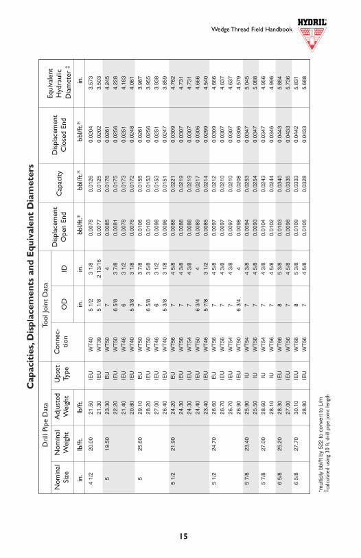
Dri
ll Pi
pe D
ata
Too
l Joi
nt D
ata
in.
lb/ft
.lb
/ft.
in.
in.
bbl/f
t.*
bb
l/ft.*
bbl
/ft.*
in.
4 1/
220
.00
21.5
0IE
UW
T40
5 1/
23
1/8
0.00
780.
0126
0.02
043.
573
21.3
0IE
UW
T39
5 1/
82
13/1
60.
0077
0.01
250.
0202
3.50
3
519
.50
23.3
0E
UW
T50
74
0.00
850.
0176
0.02
614.
245
22.2
0IE
UW
T50
6 5/
83
7/8
0.00
810.
0175
0.02
564.
228
21.4
0IE
UW
T46
63
1/2
0.00
780.
0173
0.02
514.
163
20.8
0IE
UW
T40
5 3/
83
1/8
0.00
760.
0172
0.02
484.
061
525
.60
29.1
0E
UW
T50
73
7/8
0.01
060.
0155
0.02
613.
987
28.2
0IE
UW
T50
6 5/
83
5/8
0.01
030.
0153
0.02
563.
955
27.0
0IE
UW
T46
63
1/2
0.00
980.
0153
0.02
513.
938
26.4
0IE
UW
T40
5 3/
83
1/8
0.00
960.
0151
0.02
473.
859
5 1/
221
.90
24.2
0E
UW
T56
74
5/8
0.00
880.
0221
0.03
094.
762
24.3
0IE
UW
T56
74
3/8
0.00
880.
0219
0.03
074.
731
24.3
0IE
UW
T54
74
3/8
0.00
880.
0219
0.03
074.
731
24.4
0IE
UW
T50
6 3/
44
0.00
890.
0217
0.03
064.
666
23.4
0IE
UW
T46
5 7/
83
1/2
0.00
850.
0214
0.02
994.
540
5 1/
224
.70
26.6
0E
UW
T56
74
5/8
0.00
970.
0212
0.03
094.
666
26.7
0IE
UW
T56
74
3/8
0.00
970.
0210
0.03
074.
637
26.7
0IE
UW
T54
74
3/8
0.00
970.
0210
0.03
074.
637
26.9
0IE
UW
T50
6 3/
44
0.00
980.
0208
0.03
064.
579
5 7/
823
.40
25.9
0IU
WT
547
4 3/
80.
0094
0.02
530.
0347
5.04
5
25.5
0IU
WT
567
4 5/
80.
0093
0.02
540.
0347
5.08
8
5 7/
827
.00
28.6
0IU
WT
547
4 3/
80.
0104
0.02
430.
0347
4.95
6
28.1
0IU
WT
567
4 5/
80.
0102
0.02
440.
0346
4.99
6
6 5/
825
.20
28.3
0IE
UW
T66
85
3/8
0.01
030.
0340
0.04
435.
884
27.0
0IE
UW
T56
74
5/8
0.00
980.
0335
0.04
335.
736
6 5/
827
.70
30.1
0IE
UW
T66
85
3/8
0.01
090.
0333
0.04
425.
831
28.8
0IE
UW
T56
74
5/8
0.01
050.
0328
0.04
335.
688
Cap
acit
ies,
Dis
plac
emen
ts a
nd E
quiv
alen
t D
iam
eter
s
2 3/
86.
657.
20E
UW
T26
3 3/
81
3/4
0.00
260.
0032
0.00
581.
810
7.10
EU
WT
233
1/8
1 1/
20.
0026
0.00
310.
0057
1.78
0
2 7/
810
.40
11.3
0E
UW
T31
4 1/
82
0.00
410.
0045
0.00
862.
137
10.5
0IU
WT
263
3/8
1 3/
40.
0038
0.00
440.
0082
2.10
5
10.5
0IU
WT
233
1/8
1 1/
20.
0038
0.00
440.
0082
2.04
3
10.5
0E
UW
T14
S3
3/8
1.97
50.
0038
0.00
450.
0083
2.13
6
3 1/
213
.30
14.5
0E
UW
T38
4 3/
42
9/16
0.00
530.
0073
0.01
262.
742
14.9
0E
UW
T38
52
9/16
0.00
540.
0073
0.01
272.
742
13.9
0IU
WT
314
1/8
20.
0051
0.00
720.
0123
2.63
6
3 1/
215
.50
16.7
0E
UW
T38
4 3/
42
1/2
0.00
610.
0065
0.01
262.
592
17.1
0E
UW
T38
52
1/2
0.00
620.
0065
0.01
272.
592
16.2
0IE
UW
T31
4 1/
82
0.00
590.
0064
0.01
232.
514
414
.00
16.0
0E
UW
T40
5 1/
23
1/8
0.00
580.
0107
0.01
653.
317
15.3
0IU
WT
395
2 13
/16
0.00
560.
0106
0.01
623.
268
15.5
0IU
WT
395
1/8
2 13
/16
0.00
560.
0106
0.01
623.
268
15.2
0IU
WT
384
3/4
2 9/
160.
0055
0.01
050.
0160
3.20
9
15.6
0IU
WT
385
2 9/
160.
0057
0.01
050.
0162
3.20
9
14.7
0IU
WT
314
1/8
20.
0053
0.01
040.
0157
3.00
0
415
.70
17.6
0E
UW
T40
5 1/
23
1/8
0.00
640.
0102
0.01
663.
229
16.9
0IU
WT
395
2 13
/16
0.00
610.
0100
0.01
613.
186
17.1
0IU
WT
395
1/8
2 13
/16
0.00
620.
0100
0.01
623.
186
17.1
0IU
WT
385
2 9/
160.
0062
0.00
990.
0161
3.13
4
16.2
0IU
WT
314
1/8
20.
0059
0.00
980.
0157
2.94
4
4 1/
216
.60
19.1
0E
UW
T46
6 1/
43
1/2
0.00
690.
0141
0.02
103.
789
17.8
0IE
UW
T40
5 1/
23
1/8
0.00
650.
0139
0.02
043.
724
17.6
0IE
UW
T39
5 1/
82
13/1
60.
0064
0.01
370.
0201
3.63
9
4 1/
220
.00
22.5
0E
UW
T46
6 1/
43
1/2
0.00
820.
0128
0.02
103.
626
Cap
acit
ies,
Dis
plac
emen
ts a
nd E
quiv
alen
t D
iam
eter
s
Wedge Thread Field Handbook Wedge Thread Field Handbook
14 15
*mul
tiply
bbl
/ft b
y 52
2 to
con
vert
to
L/m
‡ cal
cula
ted
usin
g 30
ft.d
rill
pipe
join
t le
ngth
*mul
tiply
bbl
/ft b
y 52
2 to
con
vert
to
L/m
‡ cal
cula
ted
assu
min
g 30
ft.
drill
pip
e jo
int
leng
th
Equi
vale
ntH
ydra
ulic
Dia
met
er ‡
Dis
plac
emen
tO
pen
End
Dis
plac
emen
tC
lose
d En
dID
O
DC
onne
c-tio
nU
pset
Type
Adj
uste
dW
eigh
tN
omin
alW
eigh
tN
omin
alSi
zeC
apac
ity
Equi
vale
ntH
ydra
ulic
Dia
met
er ‡
Dis
plac
emen
tO
pen
End
Dis
plac
emen
tC
lose
d En
dID
O
DC
onne
c-tio
nU
pset
Type
Adj
uste
dW
eigh
tN
omin
alW
eigh
tN
omin
alSi
zeC
apac
ity
Dri
ll Pi
pe D
ata
Too
l Joi
nt D
ata
in.
lb/ft
.lb
/ft.
in.
in.
bbl/f
t.*
bbl
/ft.*
bbl
/ft.*
in.
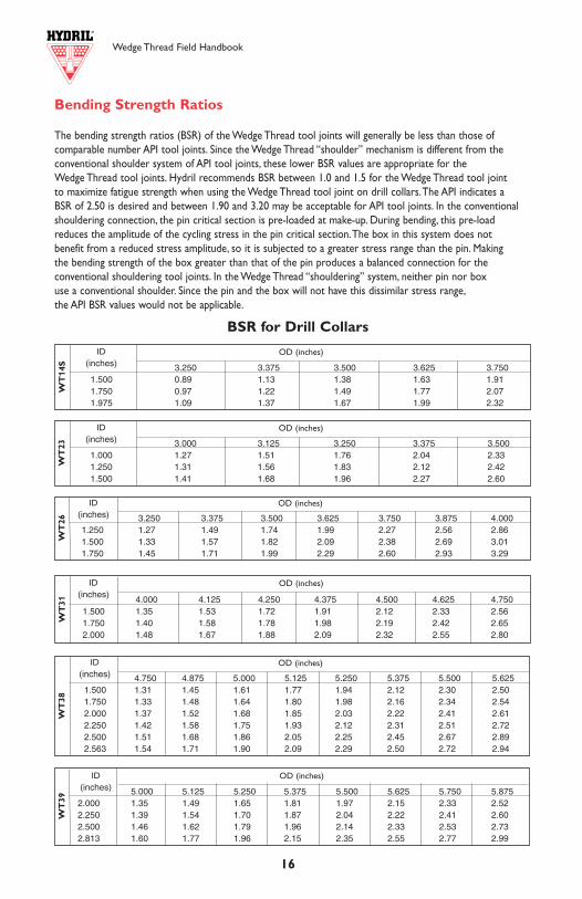
Wedge Thread Field Handbook Wedge Thread Field Handbook
16 13
Bending Strength Ratios
The bending strength ratios (BSR) of the Wedge Thread tool joints will generally be less than those of comparable number API tool joints. Since the Wedge Thread “shoulder” mechanism is different from the conventional shoulder system of API tool joints, these lower BSR values are appropriate for the Wedge Thread tool joints. Hydril recommends BSR between 1.0 and 1.5 for the Wedge Thread tool joint to maximize fatigue strength when using the Wedge Thread tool joint on drill collars.The API indicates a BSR of 2.50 is desired and between 1.90 and 3.20 may be acceptable for API tool joints. In the conventional shouldering connection, the pin critical section is pre-loaded at make-up. During bending, this pre-loadreduces the amplitude of the cycling stress in the pin critical section.The box in this system does not benefit from a reduced stress amplitude, so it is subjected to a greater stress range than the pin. Making the bending strength of the box greater than that of the pin produces a balanced connection for the conventional shouldering tool joints. In the Wedge Thread “shouldering” system, neither pin nor box use a conventional shoulder. Since the pin and the box will not have this dissimilar stress range,the API BSR values would not be applicable.
Capacities, Displacements, And Equivalent Diameters
Capacities and Displacements
Capacity is defined as the cross-sectional area of the pipe ID expressed in units of volume per unit length.The open end displacement refers to the cross-sectional area of steel in the pipe expressed in units of volume per unit length. Closed end displacement is the sum of the two.
Equivalent Diameters
The ID of the tool joint and the ID of the drill pipe differ. For hydraulics, an equivalent diameter (De) can bedetermined, using the following formula:
whereD1 = tool joint IDD2 = drill pipe IDL1 = tool joint length
L2 = drill pipe joint length
(L1)•(D2)4+ (L2-L1)•(D1)4 ][ (L2)•(D1)4•(D2)4De =
1/4
3.250 3.375 3.500 3.625 3.750 3.875 4.0001.250 1.27 1.49 1.74 1.99 2.27 2.56 2.861.500 1.33 1.57 1.82 2.09 2.38 2.69 3.011.750 1.45 1.71 1.99 2.29 2.60 2.93 3.29
3.250 3.375 3.500 3.625 3.7501.500 0.89 1.13 1.38 1.63 1.911.750 0.97 1.22 1.49 1.77 2.071.975 1.09 1.37 1.67 1.99 2.32
BSR for Drill Collars
4.000 4.125 4.250 4.375 4.500 4.625 4.7501.500 1.35 1.53 1.72 1.91 2.12 2.33 2.561.750 1.40 1.58 1.78 1.98 2.19 2.42 2.652.000 1.48 1.67 1.88 2.09 2.32 2.55 2.80
4.750 4.875 5.000 5.125 5.250 5.375 5.500 5.6251.500 1.31 1.45 1.61 1.77 1.94 2.12 2.30 2.501.750 1.33 1.48 1.64 1.80 1.98 2.16 2.34 2.542.000 1.37 1.52 1.68 1.85 2.03 2.22 2.41 2.612.250 1.42 1.58 1.75 1.93 2.12 2.31 2.51 2.722.500 1.51 1.68 1.86 2.05 2.25 2.45 2.67 2.892.563 1.54 1.71 1.90 2.09 2.29 2.50 2.72 2.94
WT
14S
WT
26W
T3 1
WT
38
ID(inches)
ID(inches)
ID(inches)
ID(inches)
OD (inches)
OD (inches)
OD (inches)
OD (inches)
5.000 5.125 5.250 5.375 5.500 5.625 5.750 5.8752.000 1.35 1.49 1.65 1.81 1.97 2.15 2.33 2.522.250 1.39 1.54 1.70 1.87 2.04 2.22 2.41 2.602.500 1.46 1.62 1.79 1.96 2.14 2.33 2.53 2.732.813 1.60 1.77 1.96 2.15 2.35 2.55 2.77 2.99
WT
39
ID(inches)
OD (inches)
3.000 3.125 3.250 3.375 3.5001.000 1.27 1.51 1.76 2.04 2.331.250 1.31 1.56 1.83 2.12 2.421.500 1.41 1.68 1.96 2.27 2.60
WT
23
ID(inches)
OD (inches)
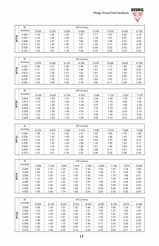
Wedge Thread Field Handbook
12
Inte
rnal
Co
atin
g R
eco
mm
enda
tio
n
Ensu
re t
hat
corr
ect
area
s ha
ve b
een
coat
ed a
nd t
hat
coat
ing
is n
ot e
xces
sive
or
mis
plac
ed.T
he p
in fa
ce a
nd t
he b
ox b
ore
shou
lder
sho
uld
be p
last
icco
ated
,with
ove
rspr
ay p
erm
itted
on
the
pin
cham
fer
and
box
fille
t ar
eas.
Ove
rspr
ay is
not
per
mitt
ed o
n th
e th
read
s as
thi
s w
ill n
ot a
llow
the
thr
eads
to e
ngag
e pr
oper
ly.
Wedge Thread Field HandbookW
T40
17
8.000 8.125 8.250 8.375 8.500 8.625 8.750 8.875 9.0003.000 1.09 1.18 1.27 1.37 1.46 1.56 1.66 1.76 1.873.500 1.13 1.22 1.32 1.42 1.51 1.62 1.72 1.83 1.934.000 1.20 1.29 1.39 1.49 1.60 1.70 1.81 1.93 2.044.500 1.30 1.41 1.51 1.62 1.74 1.85 1.97 2.10 2.224.750 1.38 1.49 1.60 1.72 1.84 1.97 2.09 2.22 2.355.000 1.48 1.60 1.73 1.85 1.98 2.11 2.25 2.39 2.535.250 1.62 1.76 1.89 2.03 2.17 2.32 2.47 2.62 2.775.375 1.72 1.86 2.00 2.14 2.29 2.45 2.60 2.77 2.93
5.250 5.375 5.500 5.625 5.750 5.875 6.000 6.1252.000 1.16 1.29 1.43 1.57 1.71 1.87 2.02 2.192.250 1.19 1.32 1.46 1.61 1.76 1.91 2.07 2.242.500 1.23 1.37 1.52 1.66 1.82 1.98 2.15 2.322.813 1.32 1.46 1.62 1.77 1.94 2.11 2.29 2.483.000 1.39 1.54 1.70 1.87 2.05 2.23 2.42 2.613.125 1.45 1.61 1.78 1.96 2.14 2.33 2.52 2.73
7.000 7.125 7.250 7.375 7.500 7.625 7.750 7.875 8.0003.000 1.04 1.14 1.24 1.34 1.45 1.56 1.67 1.79 1.903.250 1.06 1.16 1.27 1.37 1.48 1.59 1.71 1.83 1.953.500 1.10 1.20 1.31 1.42 1.53 1.64 1.76 1.89 2.013.750 1.14 1.25 1.36 1.47 1.59 1.71 1.84 1.96 2.094.000 1.20 1.31 1.43 1.55 1.67 1.80 1.93 2.06 2.204.250 1.28 1.40 1.53 1.65 1.79 1.92 2.06 2.20 2.354.500 1.39 1.52 1.66 1.80 1.94 2.09 2.24 2.39 2.554.625 1.46 1.60 1.74 1.89 2.04 2.20 2.35 2.52 2.69
WT
46
5.875 6.000 6.125 6.250 6.375 6.500 6.625 6.7502.250 1.09 1.21 1.32 1.45 1.57 1.71 1.84 1.982.500 1.11 1.23 1.35 1.48 1.61 1.74 1.88 2.032.813 1.16 1.28 1.41 1.54 1.67 1.81 1.95 2.103.000 1.19 1.32 1.45 1.58 1.72 1.87 2.02 2.173.250 1.26 1.39 1.53 1.67 1.82 1.97 2.13 2.293.500 1.35 1.49 1.64 1.79 1.95 2.11 2.28 2.46
WT
50
6.500 6.625 6.750 6.875 7.000 7.125 7.250 7.3752.500 1.09 1.20 1.31 1.42 1.54 1.66 1.78 1.912.813 1.12 1.23 1.34 1.46 1.58 1.70 1.83 1.963.000 1.14 1.26 1.37 1.49 1.61 1.73 1.86 2.003.250 1.18 1.30 1.42 1.54 1.67 1.79 1.93 2.073.500 1.24 1.36 1.48 1.61 1.74 1.88 2.02 2.163.750 1.31 1.44 1.57 1.71 1.85 1.99 2.14 2.294.000 1.42 1.56 1.70 1.85 2.00 2.15 2.31 2.48
WT
54
6.750 6.875 7.000 7.125 7.250 7.375 7.500 7.6253.000 1.09 1.19 1.30 1.41 1.52 1.64 1.76 1.883.250 1.12 1.22 1.33 1.45 1.56 1.68 1.81 1.933.500 1.16 1.27 1.38 1.50 1.62 1.75 1.88 2.013.750 1.22 1.33 1.45 1.58 1.70 1.83 1.97 2.114.000 1.29 1.42 1.55 1.68 1.81 1.95 2.09 2.244.250 1.40 1.54 1.67 1.82 1.96 2.11 2.27 2.434.375 1.47 1.61 1.76 1.91 2.06 2.22 2.38 2.55
WT
56W
T66
OD (inches)
OD (inches)
OD (inches)
OD (inches)
OD (inches)
OD (inches)
ID(inches)
ID(inches)
ID(inches)
ID(inches)
ID(inches)
ID(inches)
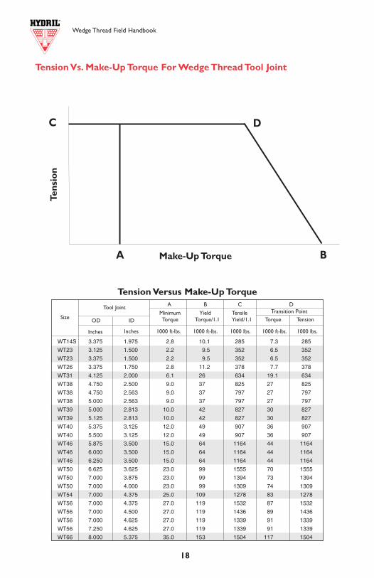
WT14S 3.375 1.975 2.8 10.1 285 7.3 285
WT23 3.125 1.500 2.2 9.5 352 6.5 352
WT23 3.375 1.500 2.2 9.5 352 6.5 352
WT26 3.375 1.750 2.8 11.2 378 7.7 378
WT31 4.125 2.000 6.1 26 634 19.1 634
WT38 4.750 2.500 9.0 37 825 27 825
WT38 4.750 2.563 9.0 37 797 27 797
WT38 5.000 2.563 9.0 37 797 27 797
WT39 5.000 2.813 10.0 42 827 30 827
WT39 5.125 2.813 10.0 42 827 30 827
WT40 5.375 3.125 12.0 49 907 36 907
WT40 5.500 3.125 12.0 49 907 36 907
WT46 5.875 3.500 15.0 64 1164 44 1164
WT46 6.000 3.500 15.0 64 1164 44 1164
WT46 6.250 3.500 15.0 64 1164 44 1164
WT50 6.625 3.625 23.0 99 1555 70 1555
WT50 7.000 3.875 23.0 99 1394 73 1394
WT50 7.000 4.000 23.0 99 1309 74 1309
WT54 7.000 4.375 25.0 109 1278 83 1278
WT56 7.000 4.375 27.0 119 1532 87 1532
WT56 7.000 4.500 27.0 119 1436 89 1436
WT56 7.000 4.625 27.0 119 1339 91 1339
WT56 7.250 4.625 27.0 119 1339 91 1339
WT66 8.000 5.375 35.0 153 1504 117 1504
Wedge Thread Field Handbook Wedge Thread Field Handbook
18 11
AP
I D
esig
nati
ons
The
dia
gram
bel
ow s
how
s th
e le
ngth
s fo
r th
e va
riou
s to
ol jo
int
com
pone
nts
as d
esig
nate
d in
Spe
cific
atio
n fo
r R
otar
y D
rill
Stem
Ele
men
ts,A
PISp
ecifi
catio
n 7
(Spe
c 7)
,Thi
rty-
Nin
th E
ditio
n,Ju
ne 1
,199
8.Si
nce
the
Wed
ge T
hrea
d to
ol jo
int
conn
ectio
n de
velo
ps it
s hi
gh t
orqu
e st
reng
th in
the
flan
ksof
the
thr
ead,
the
leng
th o
f the
thr
ead
is s
igni
fican
tly g
reat
er t
han
that
of A
PI t
ool j
oint
con
nect
ions
.Bec
ause
of t
his
grea
ter
conn
ectio
n le
ngth
,the
val
-ue
s fo
r bo
th t
he t
ong
spac
e to
lera
nce
on n
ew W
edge
Thr
ead
tool
join
ts a
nd t
he m
inim
um r
ecom
men
ded
tong
spa
ce fo
r us
ed W
edge
Thr
ead
tool
join
ts d
iffer
from
the
req
uire
men
ts fo
r A
PI t
ool j
oint
s.
On
API
too
l joi
nts,
Tabl
e 7
of S
peci
ficat
ion
7 ca
lls fo
r a
tong
spa
ce t
oler
ance
of ±
1/4"
for
Lpb
and
Lb.F
or t
he 4
thr
eads
per
inch
API
too
l joi
nt t
hrea
ds,
this
is s
uffic
ient
tol
eran
ce t
o pe
rmit
min
or r
ewor
k du
ring
man
ufac
ture
,the
reby
elim
inat
ing
exce
ssiv
e m
ater
ial l
oss.
To fa
cilit
ate
man
ufac
ture
of t
heco
arse
r Wed
ge T
hrea
d,ha
ving
as
few
as
2 th
read
s pe
r in
ch,t
ool j
oint
s ar
e m
ade
usin
g a
tong
spa
ce t
oler
ance
of -
1/4"
,+3/
4".T
his
expa
nded
tol
eran
ceba
nd p
rovi
des
the
sam
e m
inim
um t
ong
spac
e w
ith t
he p
oten
tial f
or in
crea
sed
tong
spa
ce.
Tension Vs. Make-Up Torque For Wedge Thread Tool Joint
Tension Versus Make-Up TorqueA B C D
Minimum Yield TensileTorque Torque/1.1 Yield/1.1 Torque Tension
Make-Up Torque
C D
BA
Tens
ion
Tool Joint
Inches Inches 1000 lbs.1000 ft-lbs.1000 lbs.1000 ft-lbs.1000 ft-lbs.
Size IDOD
Transition Point
Wedge Thread Field Handbook
10 19
Term
ino
logy
The
follo
win
g ill
ustr
atio
n w
ill a
ssis
t in
the
und
erst
andi
ng a
nd id
entif
icat
ion
of t
he v
ario
us H
ydri
l Wed
ge T
hrea
d D
rill
Pipe
Too
l Joi
nt fe
atur
es.
Not
e:W
T14
S us
es a
sin
gle
step
thr
ead
prof
ile a
nd d
oes
not
inco
rpor
ate
the
stre
ss r
educ
tion
groo
ve o
r th
e th
read
wea
r in
dica
tor.
*Gap
mus
t alw
ays
be p
rese
nt a
fter
mak
e-up
.
Too
lJo
int
OD
PIN
BO
X
Str
ess
Red
uct
ion
Gro
ove
s
Bev
elD
iam
eter
Bo
xF
ace
Pin
Fac
eW
ear
Ind
icat
or
Gap
*L
ast
En
gag
edT
hre
ado
fP
in
Bo
xB
ore
Sh
ou
lder
Bo
xR
oo
t/P
inC
rest
Bo
xC
rest
/Pin
Ro
ot
Tap
ered
Lar
ge
Ste
p
Tap
ered
Sm
allS
tep
Th
read
Lo
adF
lan
k
Th
read
Sta
bF
lan
k
Too
lJo
int
ID
Th
read
Wea
rIn
dic
ato
r
INSP
ECT
ION
Field Inspection (see page 10)
The Series 500 Wedge Thread drill pipe tool joint is a rugged connection and not as suscepti-ble to field damage as most connections. Unlike conventional shouldering tool joints, theWedge Thread creates a seal in the tapered thread of the small step rather than on the exter-nal shoulder. Because the threads create the seal, damage to the pin external shoulder or boxface does not require re-facing or rejection of the joint.Typical running and handling damageto the Wedge Thread can be field repaired. Damage to the pin face, pin external shoulder, boxface, and box internal shoulder can be hand dressed to remove any protrusion that wouldinterfere with make-up of the mating threads. Shoulders should not be re-faced. Repair threadsas needed.The thread surface can be dressed with a file or hand grinder and then wiped clean.The thread flanks, roots, and crests should have a relatively even surface. Inspect threads for:
• Dents and mashed areas. Damage that raises metal above the original surface will inter-fere with full engagement of pin and box and must be removed with a file or hand grinder.
• Excessive galling and scoring. Galling that wipes out threads or that cannot be dressedusing a file or hand grinder will prevent proper thread engagement and is excessive.
• Out-of-roundness that would prevent proper stabbing. A connection that is exceed-ingly out-of-round will not stab deep and will develop torque prematurely.
• Excessive rust or scale. Build-up of corrosion products will prevent proper make-up ofpin and box and should be removed.This can be done with a wire brush. Small pits and otherlocal metal loss corrosion will not interfere with proper make-up or sealing and are notcause for rejection. However, the surface should be free of pits and other surface imperfec-tions that exceed 1/16" in depth and 1/8" in diameter or extend more than 1 1/2” in lengthalong the thread helix.
• Thread protrusions. Any burrs, raised corners, or other damage projecting outward fromthe thread surface should be hand dressed until the surface is even.
The Hydril Wedge Thread tool joint inspection procedure allows drilling crews to determine if the connection warrants repairs. Hydril’s rugged design permits field repairing most of thedamage encountered by the Wedge Thread, a repair procedure that is less expensive and timeconsuming than re-cutting the tool joint.
Shoulder Gap
The Hydril Series 500 Wedge Thread drill pipe tool joint is designed with a wear indicator gapbetween the box face and the external shoulder of the pin.This gap eliminates the reactionsurface found in the torque shoulder of conventional tool joints. However, after repetitive make-up and break-out operations, the thread flanks wear permitting additional travel of the pin intothe box.This leads to a smaller gap at the external shoulder and, eventually, an engagementbetween the face of the box and the thread wear indicator projecting from the pin shoulder.The protruding shape of the thread wear indicator was designed such that it would amplydeform showing adequate signs of a nearly worn out connection.The purpose of the indicatoris to provide an allowance of several make-and-breaks before the connection is fully worn out,and ultimately indicating when the connection should be re-cut.When the connection is fullyworn out, there is full contact between the external pin shoulder and the face of the box.
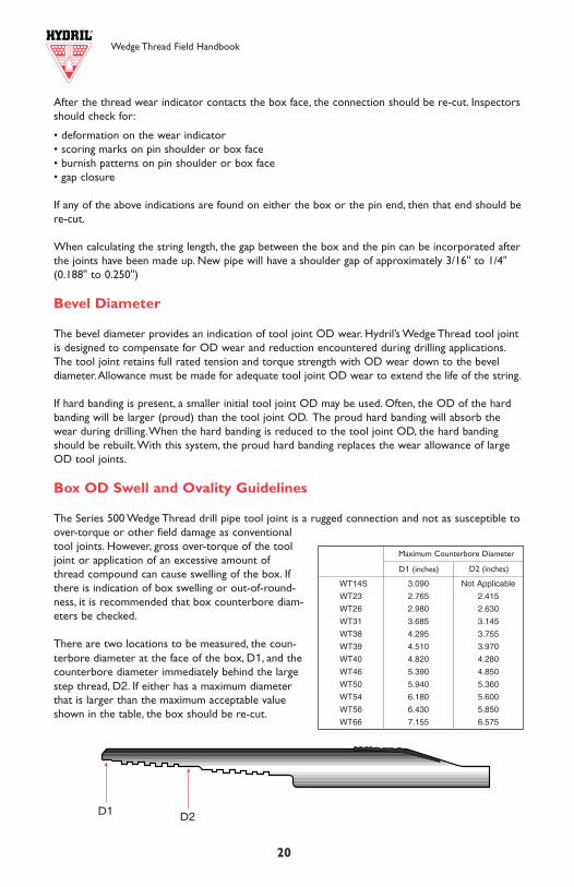
Wedge Thread Field Handbook Wedge Thread Field Handbook
20 9
After the thread wear indicator contacts the box face, the connection should be re-cut. Inspectorsshould check for:
• deformation on the wear indicator• scoring marks on pin shoulder or box face• burnish patterns on pin shoulder or box face• gap closure
If any of the above indications are found on either the box or the pin end, then that end should bere-cut.
When calculating the string length, the gap between the box and the pin can be incorporated afterthe joints have been made up. New pipe will have a shoulder gap of approximately 3/16" to 1/4"(0.188" to 0.250")
Bevel Diameter
The bevel diameter provides an indication of tool joint OD wear. Hydril’s Wedge Thread tool jointis designed to compensate for OD wear and reduction encountered during drilling applications.The tool joint retains full rated tension and torque strength with OD wear down to the beveldiameter.Allowance must be made for adequate tool joint OD wear to extend the life of the string.
If hard banding is present, a smaller initial tool joint OD may be used. Often, the OD of the hardbanding will be larger (proud) than the tool joint OD. The proud hard banding will absorb thewear during drilling.When the hard banding is reduced to the tool joint OD, the hard bandingshould be rebuilt.With this system, the proud hard banding replaces the wear allowance of largeOD tool joints.
Box OD Swell and Ovality Guidelines
The Series 500 Wedge Thread drill pipe tool joint is a rugged connection and not as susceptible toover-torque or other field damage as conventionaltool joints. However, gross over-torque of the tooljoint or application of an excessive amount ofthread compound can cause swelling of the box. Ifthere is indication of box swelling or out-of-round-ness, it is recommended that box counterbore diam-eters be checked.
There are two locations to be measured, the coun-terbore diameter at the face of the box, D1, and thecounterbore diameter immediately behind the largestep thread, D2. If either has a maximum diameterthat is larger than the maximum acceptable valueshown in the table, the box should be re-cut.
D1D2
5.50
021
.90
19.8
30.
361
5.82
8A
CO
LLA
PS
E P
RE
SS
UR
E84
1010
020
1040
010
750
1145
011
760
1267
04.
778
IDB
OD
Y Y
IELD
ST
RE
NG
TH
437
554
583
612
670
699
787
4.65
3D
DA
PI
INT
ER
NA
L P
RE
SS
UR
E86
1010
910
1149
012
060
1321
013
780
1551
0S
DY
IELD
TO
RQ
UE
5071
064
230
6761
070
990
7776
081
140
9128
0
5.50
024
.70
22.5
60.
415
6.63
0A
CO
LLA
PS
E P
RE
SS
UR
E10
460
1293
013
480
1401
015
060
1556
017
020
4.67
0ID
BO
DY
YIE
LD S
TR
EN
GT
H49
763
066
369
676
279
689
54.
545
DD
AP
I IN
TE
RN
AL
PR
ES
SU
RE
9900
1254
013
200
1386
015
190
1585
017
830
SD
YIE
LD T
OR
QU
E56
570
7166
075
430
7920
0 86
750
9052
010
1830
5.87
523
.40
21.2
80.
361
6.25
4A
CO
LLA
PS
E P
RE
SS
UR
E74
5087
7090
8093
6099
1010
140
1082
05.
153
IDB
OD
Y Y
IELD
ST
RE
NG
TH
469
594
625
657
719
750
844
5.02
8D
DA
PI
INT
ER
NA
L P
RE
SS
UR
E80
6010
220
1075
011
290
1237
012
900
1452
0S
DY
IELD
TO
RQ
UE
5861
074
230
7814
082
050
8986
093
770
1054
90
5.87
527
.00
24.2
20.
415
7.11
9A
CO
LLA
PS
E P
RE
SS
UR
E95
6011
500
1197
012
410
1329
013
700
1489
05.
045
IDB
OD
Y Y
IELD
ST
RE
NG
TH
534
676
712
747
819
854
961
4.92
0D
DA
PI
INT
ER
NA
L P
RE
SS
UR
E92
7011
740
1236
012
980
1422
014
830
1669
0S
DY
IELD
TO
RQ
UE
6551
082
980
8734
091
710
1004
5010
4810
1179
20
6.62
525
.20
22.2
10.
330
6.52
6A
CO
LLA
PS
E P
RE
SS
UR
E47
9053
2054
2055
0056
2057
2060
405.
965
IDB
OD
Y Y
IELD
ST
RE
NG
TH
489
620
653
685
750
783
881
5.84
0D
DA
PI
INT
ER
NA
L P
RE
SS
UR
E65
4082
8087
2091
5010
020
1046
011
770
SD
YIE
LD T
OR
QU
E70
580
8940
094
110
9881
010
8220
11
2930
12
7050
6.62
527
.70
24.2
40.
362
7.12
3A
CO
LLA
PS
E P
RE
SS
UR
E58
9067
5069
4071
0074
0075
2078
105.
901
IDB
OD
Y Y
IELD
ST
RE
NG
TH
534
677
712
748
819
855
962
5.77
6D
DA
PI
INT
ER
NA
L P
RE
SS
UR
E71
7090
8095
6010
040
1100
011
470
1291
0S
DY
IELD
TO
RQ
UE
7630
096
640
1017
30
1068
10
1169
90
1220
7013
7330
Dri
ll P
ipe
Bo
dy D
ata
(Con
’t.)
MIN
IMU
M Y
IELD
ST
REN
GT
H,K
SI
7595
100
105
115
120
135
MIN
IMU
M T
ENSI
LE S
TR
ENG
TH
,KSI
9510
511
012
012
513
014
5
GR
AD
E
EX
-95
100
G-1
0511
512
0S-
135
DIA
WN
UW
PEW
ALL
WEI
GH
T
WT14S 3.090 Not Applicable
WT23 2.765 2.415
WT26 2.980 2.630
WT31 3.685 3.145
WT38 4.295 3.755
WT39 4.510 3.970
WT40 4.820 4.280
WT46 5.390 4.850
WT50 5.940 5.360
WT54 6.180 5.600
WT56 6.430 5.850
WT66 7.155 6.575
D2 (inches)
Maximum Counterbore Diameter
D1 (inches)
D1 D2
Wedge Thread Field Handbook
8 21
Thread Compound
The Series 500 Wedge Thread drill pipe tool joint creates a seal in the threads rather than onthe external shoulder. Because the threads and lubricant are used to create the seal, selectionand application of the thread compound warrants individual attention.The following proce-dures should be used when running Hydril Wedge Thread tool joints:
• Compounds That Contain Solid Fillers Are Required - These tool joints use a threadlubricant seal system for both internal pressure and external pressure. Solid particles dis-persed in the thread compound provide the fillers necessary to create the seal.
• Arctic Grade Compound Is Recommended During Freezing Weather - Normalcompounds can become stiff at low temperatures, leading to an excessive amount of com-pound applied to the tool joint.A compound that can be applied at low temperatures usinga bristle brush is recommended.
• Application - When picking up the drill pipe for the initial run into the hole, apply an evencoating of thread compound over the entire pin thread.There is no need to dope the box -thread compound will be carried into the box by the pin thread.After the first trip, applycompound sparingly to the pin or re-distribute the existing compound around the pin with-out adding thread compound.A stress reduction groove is located in the root of the largestep of the pin to prevent excess thread compound build up.
Zinc tool joint compounds and copper/graphite tool joint compounds have been used exten-sively on Hydril Wedge Thread tool joints.These compounds will provide proper performancefor the life of the tool joint.
Initial Make-up Procedure (Break-In)
Hydril has not found it necessary to use a standard break-in procedure. Initial break-in of theconnection is performed on the first trip into the hole and should include slowly making upthe pin, with its application of thread compound, to the targeted torque. No make and breakor low torque break-in is required.
Make-Up Torque
The Wedge Thread tool joint has a very broad range of acceptable make-up torques. Manyoperators prefer a make-up torque 10-20% higher than the expected operating torque.Whenthe expected operating torque is relatively low, using a make-up torque at the lower end ofthe range provides several benefits:
1. The lower make-up torques will result in less wear on the make-up equipment, i.e. hydraulictongs, rig tongs, iron roughnecks, etc.
2. A lower make-up torque requires fewer turns to make-up from the hand tight position tothe power tight position.This can reduce the running time.
3. The lower make-up torque will reduce the wear on the tool joint itself, thus extending thelife of the string.
Since additional torque does not produce additional tensile stress in the pin, downhole make-up will not create excessive stress in the tool joint. For this reason, using a lower make-uptorque while tolerating subsequent downhole make-up is recommended.
RUN
NIN
G A
ND
HA
ND
LING
4.50
016
.60
15.0
00.
337
4.40
7A
CO
LLA
PS
E P
RE
SS
UR
E10
390
1276
013
300
1382
014
850
1534
016
770
3.82
6ID
BO
DY
YIE
LD S
TR
EN
GT
H33
141
944
146
350
752
959
53.
701
DD
AP
I IN
TE
RN
AL
PR
ES
SU
RE
9830
1245
013
110
1376
015
070
1573
017
690
SD
YIE
LD T
OR
QU
E30
810
3902
041
080
4313
047
240
4929
055
450
4.50
020
.00
18.7
10.
430
5.49
8A
CO
LLA
PS
E P
RE
SS
UR
E12
960
1642
017
280
1815
019
880
2074
023
330
3.64
0ID
BO
DY
YIE
LD S
TR
EN
GT
H41
252
255
057
763
266
074
23.
515
DD
AP
I IN
TE
RN
AL
PR
ES
SU
RE
1254
015
890
1672
017
560
1923
020
070
2258
0S
DY
IELD
TO
RQ
UE
3690
046
740
4920
051
660
5658
059
040
6642
0
5.00
016
.25
14.8
80.
296
4.37
4A
CO
LLA
PS
E P
RE
SS
UR
E69
4081
1083
7086
2090
8092
8098
304.
408
IDB
OD
Y Y
IELD
ST
RE
NG
TH
328
416
437
459
503
525
590
4.28
3D
DA
PI
INT
ER
NA
L P
RE
SS
UR
E77
7098
4010
360
1088
011
910
1243
013
990
SD
YIE
LD T
OR
QU
E35
040
4439
046
730
4906
053
730
5607
063
080
5.00
019
.50
17.9
50.
362
5.27
5A
CO
LLA
PS
E P
RE
SS
UR
E99
6012
020
1252
013
000
1394
014
380
1567
04.
276
IDB
OD
Y Y
IELD
ST
RE
NG
TH
396
501
528
554
607
633
712
4.15
1D
DA
PI
INT
ER
NA
L P
RE
SS
UR
E95
0012
040
1267
013
300
1457
015
200
1710
0S
DY
IELD
TO
RQ
UE
4117
052
140
5489
057
630
6312
065
870
7410
0
5.00
025
.60
24.0
50.
500
7.06
9A
CO
LLA
PS
E P
RE
SS
UR
E13
500
1710
018
000
1890
020
700
2160
024
300
4.00
0ID
BO
DY
YIE
LD S
TR
EN
GT
H53
067
270
774
281
384
895
43.
875
DD
AP
I IN
TE
RN
AL
PR
ES
SU
RE
1313
016
630
1750
018
380
2013
021
000
2363
0Y
IELD
TO
RQ
UE
5226
066
190
6968
073
160
8013
083
610
9406
0
5.50
019
.20
16.8
90.
304
4.96
2A
CO
LLA
PS
E P
RE
SS
UR
E60
4069
4071
4073
1076
3077
6080
904.
892
IDB
OD
Y Y
IELD
ST
RE
NG
TH
372
471
496
521
571
595
670
4.76
7D
DA
PI
INT
ER
NA
L P
RE
SS
UR
E72
5091
9096
7010
160
1112
011
610
1306
0Y
IELD
TO
RQ
UE
4407
055
830
5877
061
700
6758
070
520
7933
0
Dri
ll P
ipe
Bo
dy D
ata
(Con
’t.)
MIN
IMU
M Y
IELD
ST
REN
GT
H,K
SI
7595
100
105
115
120
135
MIN
IMU
M T
ENSI
LE S
TR
ENG
TH
,KSI
9510
511
012
012
513
014
5
GR
AD
E
EX
-95
100
G-1
0511
512
0S-
135
DIA
WN
UW
PEW
ALL
WEI
GH
T
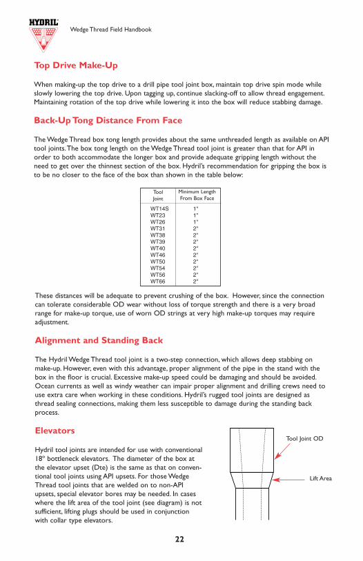
Wedge Thread Field Handbook
22
Top Drive Make-Up
When making-up the top drive to a drill pipe tool joint box, maintain top drive spin mode whileslowly lowering the top drive. Upon tagging up, continue slacking-off to allow thread engagement.Maintaining rotation of the top drive while lowering it into the box will reduce stabbing damage.
Back-Up Tong Distance From Face
The Wedge Thread box tong length provides about the same unthreaded length as available on APItool joints.The box tong length on the Wedge Thread tool joint is greater than that for API inorder to both accommodate the longer box and provide adequate gripping length without theneed to get over the thinnest section of the box. Hydril’s recommendation for gripping the box isto be no closer to the face of the box than shown in the table below:
7
2.87
510
.40
9.72
0.36
22.
858
AC
OLL
AP
SE
PR
ES
SU
RE
1651
020
910
2201
023
110
2531
026
410
2972
02.
151
IDB
OD
Y Y
IELD
ST
RE
NG
TH
214
272
286
300
329
343
386
2.02
6D
DA
PI
INT
ER
NA
L P
RE
SS
UR
E16
530
2093
022
030
2314
025
340
2644
029
750
SD
YIE
LD T
OR
QU
E11
550
1464
015
410
1618
017
720
1849
020
800
3.50
013
.30
12.3
20.
368
3.62
1A
CO
LLA
PS
E P
RE
SS
UR
E14
110
1788
018
820
1976
021
640
2258
025
400
2.76
4ID
BO
DY
YIE
LD S
TR
EN
GT
H27
234
436
238
041
643
548
92.
639
DD
AP
I IN
TE
RN
AL
PR
ES
SU
RE
1380
017
480
1840
019
320
2116
022
080
2484
0S
DY
IELD
TO
RQ
UE
1855
023
500
2474
025
970
2845
029
680
3339
0
3.50
015
.50
14.6
40.
449
4.30
4A
CO
LLA
PS
E P
RE
SS
UR
E16
770
2125
022
370
2348
025
720
2684
030
190
2.60
2ID
BO
DY
YIE
LD S
TR
EN
GT
H32
340
943
045
249
551
658
12.
477
DD
AP
I IN
TE
RN
AL
PR
ES
SU
RE
1684
021
330
2245
023
570
2582
026
940
3031
0S
DY
IELD
TO
RQ
UE
2109
026
710
2811
029
520
3233
033
740
3795
0
4.00
014
.00
12.9
50.
330
3.80
5A
CO
LLA
PS
E P
RE
SS
UR
E11
350
1438
015
140
1590
017
410
1817
020
140
3.34
0ID
BO
DY
YIE
LD S
TR
EN
GT
H28
536
138
140
043
845
751
43.
215
DD
AP
I IN
TE
RN
AL
PR
ES
SU
RE
1083
013
720
1444
015
160
1660
017
330
1949
0S
DY
IELD
TO
RQ
UE
2329
029
500
3105
032
600
3571
037
260
4192
0
4.00
015
.70
14.7
10.
380
4.32
2A
CO
LLA
PS
E P
RE
SS
UR
E12
900
1634
017
200
1805
019
770
2063
023
210
3.24
0ID
BO
DY
YIE
LD S
TR
EN
GT
H32
441
143
245
449
751
958
33.
115
DD
AP
I IN
TE
RN
AL
PR
ES
SU
RE
1247
015
790
1663
017
460
1912
019
950
2244
0S
DY
IELD
TO
RQ
UE
2581
032
690
3441
036
130
3958
041
300
4646
0
4.00
017
.00
15.9
00.
415
4.67
4A
CO
LLA
PS
E P
RE
SS
UR
E13
950
1767
018
600
1953
021
390
2232
025
110
3.17
0ID
BO
DY
YIE
LD S
TR
EN
GT
H35
144
446
749
153
856
163
13.
045
DD
AP
I IN
TE
RN
AL
PR
ES
SU
RE
1362
017
250
1816
019
060
2088
021
790
2451
0S
DY
IELD
TO
RQ
UE
2744
034
760
3659
038
420
4208
043
910
4940
0
Dri
ll P
ipe
Bo
dy D
ata
(Con
’t.)
Con
tinue
d on
Pag
e 8
MIN
IMU
M Y
IELD
ST
REN
GT
H,K
SI
7595
100
105
115
120
135
MIN
IMU
M T
ENSI
LE S
TR
ENG
TH
,KSI
9510
511
012
012
513
014
5
GR
AD
E
EX
-95
100
G-1
0511
512
0S-
135
DIA
WN
UW
PEW
ALL
WEI
GH
T
Wedge Thread Field Handbook
WT14S 1"WT23 1''WT26 1''WT31 2''WT38 2''WT39 2''WT40 2''WT46 2''WT50 2''WT54 2''WT56 2''WT66 2''
Minimum LengthFrom Box Face
These distances will be adequate to prevent crushing of the box. However, since the connectioncan tolerate considerable OD wear without loss of torque strength and there is a very broadrange for make-up torque, use of worn OD strings at very high make-up torques may requireadjustment.
Alignment and Standing Back
The Hydril Wedge Thread tool joint is a two-step connection, which allows deep stabbing onmake-up. However, even with this advantage, proper alignment of the pipe in the stand with thebox in the floor is crucial. Excessive make-up speed could be damaging and should be avoided.Ocean currents as well as windy weather can impair proper alignment and drilling crews need touse extra care when working in these conditions. Hydril’s rugged tool joints are designed asthread sealing connections, making them less susceptible to damage during the standing backprocess.
Elevators
Hydril tool joints are intended for use with conventional18º bottleneck elevators. The diameter of the box atthe elevator upset (Dte) is the same as that on conven-tional tool joints using API upsets. For those WedgeThread tool joints that are welded on to non-APIupsets, special elevator bores may be needed. In caseswhere the lift area of the tool joint (see diagram) is notsufficient, lifting plugs should be used in conjunctionwith collar type elevators.
Tool Joint OD
Lift Area
ToolJoint
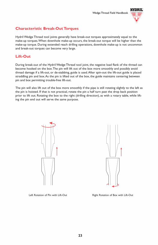
Wedge Thread Field Handbook Wedge Thread Field Handbook
6 23
MIN
IMU
M Y
IELD
ST
REN
GT
H,K
SI
7595
100
105
115
120
135
MIN
IMU
M T
ENSI
LE S
TR
ENG
TH
,KSI
9510
511
012
012
513
014
5
GR
AD
E
EX
-95
100
G-1
0511
512
0S-
135
2.37
54.
854.
440.
190
1.30
4A
CO
LLA
PS
E P
RE
SS
UR
E11
040
1398
014
720
1546
016
730
1731
019
030
1.99
5ID
BO
DY
YIE
LD S
TR
EN
GT
H98
124
130
137
150
156
176
1.87
0D
DA
PI
INT
ER
NA
L P
RE
SS
UR
E10
500
1330
014
000
1470
016
100
1680
018
900
SD
YIE
LD T
OR
QU
E47
6060
3063
5066
7073
0076
2085
70
2.37
56.
656.
270.
280
1.84
3A
CO
LLA
PS
E P
RE
SS
UR
E15
600
1976
020
800
2184
023
920
2496
028
080
1.81
5ID
BO
DY
YIE
LD S
TR
EN
GT
H13
817
518
419
421
222
124
91.
690
DD
AP
I IN
TE
RN
AL
PR
ES
SU
RE
1547
019
600
2063
021
660
2373
024
760
2785
0S
DY
IELD
TO
RQ
UE
6250
7920
8330
8750
9580
1000
011
250
2.87
56.
856.
170.
217
1.81
2A
CO
LLA
PS
E P
RE
SS
UR
E10
740
1294
013
490
1402
015
070
1556
017
030
2.44
1ID
BO
DY
YIE
LD S
TR
EN
GT
H13
617
218
119
020
821
724
52.
316
DD
AP
I IN
TE
RN
AL
PR
ES
SU
RE
9910
1255
013
210
1387
015
190
1585
017
830
SD
YIE
LD T
OR
QU
E80
8010
240
1078
011
320
1239
012
930
1455
0
Min
imum
Yie
ld -
100
0’s
of P
SI S
tren
gth
Min
imum
Ten
sile
(U
LT)
- 10
00’s
of P
SI S
tren
gth
Dri
ll P
ipe
Bo
dy D
ata
DIA
WN
UW
NW
PEW
ALL
NO
MIN
AL
OD
(IN
)N
OM
INA
LW
EIG
HT
UPS
ET(L
BS/F
T)
NO
MIN
AL
WEI
GH
TN
ON
-UPS
ET(L
BS/F
T)
PLA
IN E
ND
WEI
GH
T/F
T(L
BS/F
T)
WA
LL T
HIC
KN
ESS
(IN)
A -
AR
EA (
IN2 )
ID -
NO
MIN
AL
ID (
IN)
DD
- D
RIF
T D
IAM
ETER
(IN
)
CO
LLA
PSE
PRES
SUR
E -
Pipe
Bod
y C
olla
pse
Rat
ing
(psi
)BO
DY
YIE
LD S
TR
ENG
TH
- A
xial
Yie
ld C
apac
ity (
1000
lbs)
API
INT
ERN
AL
PRES
SUR
E -
Pipe
Bod
y M
in W
all B
urst
Rat
ing
(psi
)Y
IELD
TO
RQ
UE
- Yie
ld T
orqu
e (ft
-lbs)
Con
vers
ions
:ps
i x 6
890
= P
aft
-lbs
x 1.
36 =
N-m
Dri
ll P
ipe
Bo
dy D
ata
The
follo
win
g is
a lis
t of s
izes
and
mec
hani
cal p
rope
rtie
s of
OC
TG d
rill p
ipe
used
with
the
Hyd
ril W
edge
Thr
ead
tool
join
t
Dri
ll P
ipe
Bo
dy D
ata
Tabl
e L
egen
d
DIA
WN
UW
PEW
ALL
WEI
GH
T
Characteristic Break-Out Torques
Hydril Wedge Thread tool joints generally have break-out torques approximately equal to themake-up torques.When downhole make-up occurs, the break-out torque will be higher than themake-up torque. During extended reach drilling operations, downhole make-up is not uncommonand break-out torques can become very large.
Lift-Out
During break-out of the Hydril Wedge Thread tool joint, the negative load flank of the thread canbecome hooked on the box.The pin will lift out of the box more smoothly and possibly avoidthread damage if a lift-out, or de-stabbing, guide is used.After spin-out the lift-out guide is placedstraddling pin and box.As the pin is lifted out of the box, the guide maintains centering betweenpin and box permitting trouble-free lift-out.
The pin will also lift out of the box more smoothly if the pipe is still rotating slightly to the left asthe pin is hoisted. If that is not practical, rotate the pin a half turn past the drop back positionprior to lift out. Rotating the box to the right (drilling direction), as with a rotary table, while lift-ing the pin end out will serve the same purpose.
Left Rotation of Pin with Lift-Out Right Rotation of Box with Lift-Out
Wedge Thread Field Handbook Wedge Thread Field Handbook
24 5
Free Point and Back-Off
When using a free-point and string shot back-off system, the shot size and procedure should bethe same as the shot size and procedure used for a comparable size API tool joint.When a stringshot is used in backing-off operations, swelling of the connection may occur.To determine theextent of this swelling in the pin, make-up a good box with the pin retrieved from the well. If agood box will make-up onto this pin with little resistance and with no unusual standoff, that pin isgood and can continue to be used. In addition, minimal swelling of the box downhole may beassumed. If a good box will not make-up with the pin without excessive standoff, the pin retrievedis oversize and should be set aside for re-cutting. Continued use of an oversize pin could cause agood mating box to split.
Upon retrieving the backed-off box, if the box is not rejected for fishing tool damage, the boxcounterbore diameter should be inspected for swelling using the criteria covered in Inspection.A swollen box should be set aside for re-cutting.
In some instances, a string shot will be set off across a tool joint without backing off the string atthat location.The location in the drill string that the string shot was made should be noted so thetool joint exposed to the shot can be inspected immediately upon recovery.A tool joint that hasbeen exposed to an excessively large shot charge can cause swelling in the tool joint without anyobvious indication of damage. Continued used of a swollen box can result in a parted string dueto inadequate thread engagement. Continued use of an oversize pin could cause a good matingbox to split.
Tool
Join
t Sizeand
Style
Drill Pipe Tool Joint
Nominal Weight Grades
OD of Pin and
BoxID of Pin Bevel
Diameter
Lengthof ToolJointPin
PinTongSpace
BoxTongSpace
Comb.Lengthof PinandBox
Diameter of Box
at elevatorUpset Max.
Make-UpTorques
Min. Max
lb/ft. in. in. in. Lp Lpb Lb L Dte ft-lb.* ft-lb.*
Tool Joint Dimensions
*multiply ft-lb by 1.36 to convert to N-m
2 3/8 EU 4.85 X G 3 1/4 - 3 3/8 1.945 3 5/32 11 7 10 17 2 9/16 2800 8900
2 3/8 EU 6.65 X G 3 1/4 - 3 3/8 1 3/4 3 5/32 11 7 10 17 2 9/16 2800 8900
2 7/8 IU 6.85 X G S 3 1/4 - 3 3/8 1.975 3 5/32 11 7 10 17 3 2800 8900
2 7/8 EU 10.40 X G S 3 1/4 - 3 3/8 1.975 3 5/32 11 7 10 17 3 3/16 2800 8900
3 1/2 IU 13.30 X G S 3 9/16 1.975 3 5/32 11 7 10 17 3 11/16 2800 8900
2 3/8 EU 6.65 X G 3 1/8 1 1/2 2 15/16 12 7 10 17 2 9/16 2200 8300
2 7/8 IU 10.40 X G S 3 1/8 1 1/2 2 15/16 12 7 10 17 3 2200 8300
2 3/8 EU 6.65 X G 3 3/8 1 3/4 3 9/64 12 7 10 17 2 9/16 2800 9800
2 7/8 IU 10.40 X G S 3 3/8 1 3/4 3 9/64 12 7 10 17 3 2800 9800
2 7/8 EU 10.40 X G S 4 1/8 2 3 29/32 14 7 12 19 3 3/16 6200 22500
3 1/2 IU 13.30 X G S 4 1/8 2 3 29/32 14 7 12 19 3 11/16 6200 22500
3 1/2 IEU 15.50 X G S 4 1/8 2 3 29/32 14 7 12 19 3 7/8 6200 22500
4 IU 14.00 - 17.00 X G S 4 1/8 2 3 29/32 14 7 12 19 4 1/8 6200 22500
3 1/2 EU 13.30 X G S 4 3/4 - 5 2 9/16 4 9/16 15 8 14 22 3 7/8 9000 31500
3 1/2 EU 15.50 X G S 4 3/4 - 5 2 1/2 4 9/16 15 8 14 22 3 7/8 9000 31500
4 IU 14.00 - 17.00 X G S 4 3/4 - 5 2 9/16 4 9/16 15 8 14 22 4 3/16 9000 31500
4 1/2 IU 16.60 - 20.00 X G S 4 3/4 2 9/16 4 9/16 15 8 14 22 4 11/16 9000 31500
4 IU 14.00 - 17.00 X G S 5 - 5 1/8 2 13/16 4 13/16 15 8 14 22 4 3/16 10000 36000
4 1/2 IEU 16.60 - 20.00 X G S 5 1/8 2 13/16 4 13/16 15 8 14 22 4 11/16 10000 36000
5 IEU 19.50 - 25.60 X G S 5 1/8 2 13/16 4 13/16 15 8 14 22 5 1/8 10000 36000
4 EU 14.00 - 17.00 X G S 5 1/2 3 1/8 5 1/8 15 8 14 22 4 1/2 12000 42000
4 1/2 IEU 16.60 - 20.00 X G S 5 1/2 3 1/8 5 1/8 15 8 14 22 4 11/16 12000 42000
5 IEU 19.50 - 25.60 X G S 5 3/8 3 1/8 5 1/8 15 8 14 22 5 1/8 12000 42000
4 1/2 EU 16.60 - 20.00 X G S 6 - 6 1/4 3 1/2 5 3/4 15 8 14 22 5 15000 56000
5 IEU 19.50 - 25.60 X G S 6 3 1/2 5 3/4 15 8 14 22 5 1/8 15000 56000
5 1/2 IEU 21.90 - 24.70 X G S 5 7/8 3 1/2 5 3/4 15 8 14 22 5 11/16 15000 56000
5 EU 19.50 X G S 6 3/4 - 7 4 6 11/32 16 8 15 23 5 11/16 23000 86000
5 EU 25.60 X G S 6 3/4 - 7 3 7/8 6 11/32 16 8 15 23 5 11/16 23000 86000
5 IEU 19.50 X G S 6 5/8 3 7/8 6 11/32 16 8 15 23 5 1/8 23000 86000
5 IEU 25.60 X G S 6 5/8 3 5/8 6 11/32 16 8 15 23 5 1/8 23000 86000
5 1/2 IEU 21.90 - 24.70 X G S 6 3/4 - 7 4 6 11/32 16 8 15 23 5 11/16 23000 86000
5 1/2 IEU 21.90 - 24.70 X G S 7 4 3/8 6 5/8 16 8 15 23 5 11/16 25000 90000
5 7/8 IU 23.40 - 27.00 X G S 7 4 3/8 6 5/8 16 8 15 23 5 15/16 25000 90000
5 1/2 EU 21.90 - 24.70 X G S 7 - 7 1/4 4 5/8 6 7/8 16 8 15 23 6 27000 99000
5 1/2 IEU 21.90 - 24.70 X G S 7 - 7 1/4 4 3/8 6 7/8 16 8 15 23 5 11/16 27000 99000
5 7/8 IU 23.40 - 27.00 X G S 7 4 5/8 6 7/8 16 8 15 23 5 15/16 27000 99000
6 5/8 IEU 25.20 - 27.70 X G S 7 4 5/8 6 7/8 16 8 15 23 6 57/64 27000 99000
6 5/8 IEU 25.20 - 27.70 X G S 8 5 3/8 7 45/64 18 10 16 26 6 57/64 35000 120000
WT
23
WT
14S
WT
31W
T38
WT
39W
T40
WT
46W
T50
WT
54W
T56
WT
66W
T26
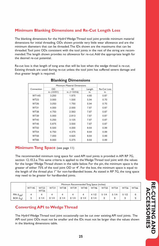
Wedge Thread Field Handbook
4 25
NominalSize
Drill Pipe Data Tool Joint Data Mechanical Properties
NominalWeight
AdjustedWeight Type Upset Connec-
tionOD ID Drift Tool
JointToolJoint
TorsionalRatio
in. lb/ft. lb/ft. in. in. in. 1000 lb. 1000 lb. ft-lb.* ft-lb.*
4 1/2 20.00 22.00 EU-135 WT46 6 3 1/2 3.375 742 1280 66420 70000 1.05
22.50 EU-135 WT46 6 1/4 3 1/2 3.375 742 1280 66420 70000 1.05
21.50 IEU-135 WT40 5 1/2 3 1/8 3.000 742 998 66420 54000 0.81
21.30 IEU-135 WT39 5 1/8 2 13/16 2.688 742 910 66420 46000 0.69
20.80 IU-135 WT38 4 5/8 2 9/16 2.438 742 877 66420 41000 0.62
5 19.50 22.70 EU-135 WT50 6 3/4 4 3.875 712 1440 74100 109000 1.47
23.30 EU-135 WT50 7 4 3.875 712 1440 74100 109000 1.47
22.20 IEU-135 WT50 6 5/8 3 7/8 3.750 712 1533 74100 109000 1.47
21.40 IEU-135 WT46 6 3 1/2 3.375 712 1280 74100 70000 0.94
20.80 IEU-135 WT40 5 3/8 3 1/8 3.000 712 998 74100 54000 0.73
20.80 IEU-135 WT39 5 1/8 2 13/16 2.688 712 910 74100 46000 0.62
5 25.60 28.50 EU-135 WT50 6 3/4 3 7/8 3.750 954 1533 94060 109000 1.16
29.10 EU-135 WT50 7 3 7/8 3.750 954 1533 94060 109000 1.16
28.20 IEU-135 WT50 6 5/8 3 5/8 3.500 954 1710 94060 109000 1.16
27.00 IEU-135 WT46 6 3 1/2 3.375 954 1280 94060 70000 0.74
26.40 IEU-135 WT40 5 3/8 3 1/8 3.000 954 998 94060 54000 0.57
26.40 IEU-135 WT39 5 1/8 2 13/16 2.688 954 910 94060 46000 0.49
5 1/2 21.90 24.20 EU-135 WT56 7 4 5/8 4.500 787 1473 91280 132000 1.45
24.70 EU-135 WT56 7 1/4 4 5/8 4.500 787 1473 91280 132000 1.45
24.30 IEU-135 WT56 7 4 3/8 4.250 787 1685 91280 132000 1.45
24.90 IEU-135 WT56 7 1/4 4 3/8 4.250 787 1685 91280 132000 1.45
24.30 IEU-135 WT54 7 4 3/8 4.250 787 1406 91280 120000 1.31
24.40 IEU-135 WT50 6 3/4 4 3.875 787 1440 91280 109000 1.19
25.00 IEU-135 WT50 7 4 3.875 787 1440 91280 109000 1.19
23.40 IEU-135 WT46 5 7/8 3 1/2 3.375 787 1280 91280 70000 0.77
5 1/2 24.70 26.60 EU-135 WT56 7 4 5/8 4.500 895 1473 101830 132000 1.30
27.20 EU-135 WT56 7 1/4 4 5/8 4.500 895 1473 101830 132000 1.30
26.70 IEU-135 WT56 7 4 3/8 4.250 895 1685 101830 132000 1.30
27.30 IEU-135 WT56 7 1/4 4 3/8 4.250 895 1685 101830 132000 1.30
26.70 IEU-135 WT54 7 4 3/8 4.250 895 1406 101830 120000 1.18
26.90 IEU-135 WT50 6 3/4 4 3.875 895 1440 101830 109000 1.07
27.40 IEU-135 WT50 7 4 3.875 895 1440 101830 109000 1.07
25.80 IEU-135 WT46 5 7/8 3 1/2 3.375 895 1280 101830 70000 0.69
5 7/8 23.40 25.90 IU-135 WT54 7 4 3/8 4.250 844 1406 105490 120000 1.14
25.50 IU-135 WT56 7 4 5/8 4.500 844 1473 105490 132000 1.25
5 7/8 27.00 28.60 IU-135 WT54 7 4 3/8 4.250 961 1406 117920 120000 1.02
28.10 IU-135 WT56 7 4 5/8 4.500 961 1473 117920 132000 1.12
6 5/8 25.20 28.30 IEU-135 WT66 8 5 3/8 5.250 881 1654 127050 168000 1.32
27.00 IEU-135 WT56 7 4 5/8 4.500 881 1473 127050 132000 1.04
6 5/8 27.70 30.10 IEU-135 WT66 8 5 3/8 5.250 962 1654 137330 168000 1.22
28.80 IEU-135 WT56 7 4 5/8 4.500 962 1473 137330 132000 0.96
Performance Data Con’t.
*multiply ft-lb by 1.36 to convert to N-m
Minimum Tong Space (see page 11)
The recommended minimum tong space for used API tool joints is provided in API RP 7G,section 12.10.2.e.This same criteria is applied to the Wedge Thread tool joint with the valuesfor the longer Wedge Thread shown in the table below. For the pin, the minimum space is thegreater of either 75% of the tool joint OD or 4". For the box, the minimum space is equal tothe length of the thread plus 1" for non-hardbanded boxes. As stated in RP 7G, the tong spacemay need to be greater for hardbanded joints.
RE
-CU
TT
ING
AN
D
AC
CE
SS
OR
IES
WT14S 3.250 1.975 4.60 0.87
WT23 3.000 1.500 5.94 0.70
WT26 3.250 1.750 5.94 0.70
WT31 4.000 2.000 7.87 0.87
WT38 4.750 2.563 7.87 0.87
WT39 5.000 2.813 7.87 0.87
WT40 5.250 3.125 7.87 0.87
WT46 5.875 3.500 7.87 0.87
WT50 6.500 4.000 8.64 0.99
WT54 6.750 4.375 8.64 0.99
WT56 7.000 4.625 8.64 0.99
WT66 8.000 5.375 8.64 0.99
Minimum Blanking Dimensions and Re-Cut Length Loss
The blanking dimensions for the Hydril Wedge Thread tool joint provide minimum materialdimensions for initial threading. ODs shown provide very little wear allowance and are theminimum diameters that can be threaded.The IDs shown are the maximums that can bethreaded.Tool joint ODs consistent with the tool joints in the rest of the string are recom-mended.The length shown provides no allowance for re-cut.Add the appropriate length for the desired re-cut potential.
Re-cut loss is that length of tong area that will be lost when the wedge thread is re-cut.Existing threads are used during re-cut unless the tool joint has suffered severe damage andthus greater length is required.
Minimum Material Dimensions
Re-Cut Lossin.
Lengthin.
IDin. (+ 0.016)
ODin. (-0.031)
Connection
Torsional YieldTensile Yield
Blanking Dimensions
Pipe Pipe
Converting API to Wedge Thread
The Hydril Wedge Thread tool joint occasionally can be cut over existing API tool joints. TheAPI tool joint ODs must not be smaller and the IDs must not be larger than the values shownin the blanking dimensions table.
PIN (Lpb) 4 4 4 4 4 4 4 1/2 5 1/4 5 1/4 5 1/2 6
BOX (Lb) 5 6 1/4 8 1/4 8 1/4 8 1/4 8 1/4 8 1/4 9 9 9 9
Minimum Recommended Tong Space (inches)
WT14S WT23 WT31 WT38 WT39 WT40 WT46 WT50 WT54 WT56 WT66WT26
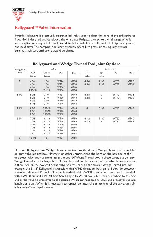
NominalSize
Drill Pipe Data Tool Joint Data Mechanical Properties
NominalWeight
AdjustedWeight Type Upset Connec-
tionOD ID Drift
Torsional Yield
Pipe ToolJoint
Tensile Yield
Pipe ToolJoint
TorsionalRatio
in. lb/ft. lb/ft. in. in. in. 1000 lb. 1000 lb. ft-lb.* ft-lb.*2 3/8 6.65 7.20 EU-105 WT26 3 3/8 1 3/4 1.625 194 416 8750 12300 1.41
7.10 EU-105 WT23 3 1/8 1 1/2 1.375 194 387 8750 10400 1.19
7.20 EU-105 WT14S 3 3/8 1 3/4 1.625 194 314 8750 11100 1.27
2 7/8 10.40 11.30 EU-135 WT31 4 1/8 2 1.875 386 697 20800 28500 1.37
10.50 IU-135 WT26 3 3/8 1 3/4 1.625 386 416 20800 12300 0.59
10.50 IU-135 WT23 3 1/8 1 1/2 1.375 386 387 20800 10400 0.50
10.50 EU-135 WT14S 3 3/8 1.975 1.875 386 314 20800 11100 0.53
3 1/2 13.30 14.50 EU-135 WT38 4 3/4 2 9/16 2.438 489 877 33390 41000 1.23
14.90 EU-135 WT38 5 2 9/16 2.438 489 877 33390 41000 1.23
13.90 IU-135 WT31 4 1/8 2 1.875 489 697 33390 28500 0.85
13.40 IU-135 WT26 3 9/16 1 3/4 1.625 489 416 33390 12300 0.37
3 1/2 15.50 16.70 EU-135 WT38 4 3/4 2 1/2 2.375 581 907 37950 41000 1.08
17.10 EU-135 WT38 5 2 1/2 2.375 581 907 37950 41000 1.08
16.20 IEU-135 WT31 4 1/8 2 1.875 581 697 37950 28500 0.75
4 14.00 15.80 EU-135 WT40 5 3/8 3 1/8 3.000 514 998 41920 54000 1.29
16.00 EU-135 WT40 5 1/2 3 1/8 3.000 514 998 41920 54000 1.29
15.30 IU-135 WT39 5 2 13/16 2.688 514 910 41920 46000 1.10
15.50 IU-135 WT39 5 1/8 2 13/16 2.688 514 910 41920 46000 1.10
15.20 IU-135 WT38 4 3/4 2 9/16 2.438 514 877 41920 41000 0.98
15.60 IU-135 WT38 5 2 9/16 2.438 514 877 41920 41000 0.98
14.70 IU-135 WT31 4 1/8 2 1.875 514 697 41920 28500 0.68
4 15.70 17.40 EU-135 WT40 5 3/8 3 1/8 3.000 583 998 46460 54000 1.16
17.60 EU-135 WT40 5 1/2 3 1/8 3.000 583 998 46460 54000 1.16
16.90 IU-135 WT39 5 2 13/16 2.688 583 910 46460 46000 0.99
17.10 IU-135 WT39 5 1/8 2 13/16 2.688 583 910 46460 46000 0.99
16.80 IU-135 WT38 4 3/4 2 9/16 2.438 583 877 46460 41000 0.88
17.10 IU-135 WT38 5 2 9/16 2.438 583 877 46460 41000 0.88
16.20 IU-135 WT31 4 1/8 2 1.875 583 697 46460 28500 0.61
4 1/2 16.60 18.60 EU-135 WT46 6 3 1/2 3.375 595 1280 55450 70000 1.26
19.10 EU-135 WT46 6 1/4 3 1/2 3.375 595 1280 55450 70000 1.26
17.80 IEU-135 WT40 5 1/2 3 1/8 3.000 595 998 55450 54000 0.97
17.60 IEU-135 WT39 5 1/8 2 13/16 2.688 595 910 55450 46000 0.83
17.10 IU-135 WT38 4 5/8 2 9/16 2.438 595 877 55450 41000 0.74
Wedge Thread Field Handbook
326
The Wedge ThreadTM Drill Pipe Tool Joint
“The Series 500™ Wedge Thread™ drill pipe tool joint is a tapered, two-step threaded connection.The pipe body sealing capability of the Wedge Thread is provided by the tapered,dovetail Wedge Thread and the lubricant. A comprehensive process of designing and testing ledto the initial exhibition of a proto-type two-step, tapered configuration at the Aberdeen Oil Show in September, 1993. Since that time, the Wedge Thread has become recognized as theindustry leader in drill pipe tool joint technology, as evidenced by its universal applicationincluding the North Sea, Africa, Gulf of Mexico, Australia, Southeast Asia, Canada, SouthAmerica and Mexico. The following tables contain performance data and dimensions for theSeries 500™ Wedge Thread™ drill pipe tool joint.”
PR
OD
UC
T
Performance Data
*multiply ft-lb by 1.36 to convert to N-m Continued on Page 4
3 4 3/4 1 3/4 WT26 WT38 4 3/4 2 1/8 WT38 WT264 3/4 1 3/4 WT31 WT38 4 3/4 2 1/8 WT38 WT314 3/4 1 3/4 WT38 WT38
4 15/16 2 1/16 WT38 WT38
3 1/2 5 3/8 2 1/4 WT38 WT40 5 3/8 3 WT40 WT385 3/8 2 1/4 WT39 WT40 5 3/8 3 WT40 WT395 3/8 2 1/4 WT40 WT406 1/8 2 1/4 WT46 WT46
4 1/4 6 5/8 2 13/16 WT40 WT46 6 3 1/2 WT46 WT406 5/8 2 13/16 WT46 WT466 5/8 2 13/16 WT50 WT50
5 1/4 7 3/8 3 1/16 WT40 WT50 6 1/2 3 1/2 WT50 WT407 3/8 3 1/16 WT46 WT50 6 1/2 4 WT50 WT467 3/8 3 1/16 WT50 WT507 3/8 3 1/16 WT54 WT547 3/4 3 1/16 WT56 WT56
8 3 1/16 WT66 WT66
6 10 1/2 5 WT84 WT84
KellyguardSize
On some Kellyguard and Wedge Thread combinations, the desired Wedge Thread size is availableon both valve pin and box. However, on other combinations, the bore on the box end of the one piece valve body prevents using the desired Wedge Thread box. In these cases, a larger sizeWedge Thread with its larger box ID must be used on the box end of the valve. A crossover subis then used on the box end of the valve to cross back to the smaller Wedge Thread size. Forexample, the 3 1/2" Kellyguard is available with a WT40 thread on both pin and box. No crossoveris needed. However, if the 3 1/2" valve is desired with a WT38 connection, the valve is threadedwith a WT38 pin and a WT40 box.A WT40 pin by WT38 box sub is then bucked-on to the boxend of the valve to crossover to the desired WT38 connection.The valve and crossover sub arehandled as a unit.When it is necessary to replace the internal components of the valve, the subis bucked-off and repairs made.
Kellyguard and Wedge Thread Tool Joint OptionsValve Crossover
Kellyguard™ Valve Information
Hydril’s Kellyguard is a manually operated ball valve used to close the bore of the drill string toflow. Hydril designed and developed the one piece Kellyguard to serve the full range of kellyvalve applications: upper kelly cock, top drive kelly cock, lower kelly cock, drill pipe safety valve,and mud saver.The compact, one piece assembly offers high pressure sealing, high tensionstrength, high torsional strength, and durability.
inches inches inches inchesPinOD Ball ID Box OD ID Pin Box
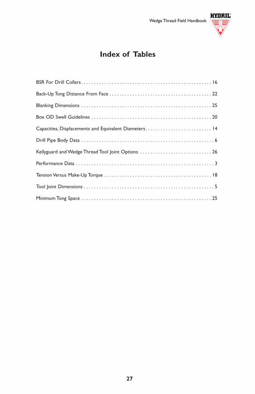
Wedge Thread Field Handbook
2 27
Index of Tables
BSR For Drill Collars . . . . . . . . . . . . . . . . . . . . . . . . . . . . . . . . . . . . . . . . . . . . . . . . . . . 16
Back-Up Tong Distance From Face . . . . . . . . . . . . . . . . . . . . . . . . . . . . . . . . . . . . . . . . 22
Blanking Dimensions . . . . . . . . . . . . . . . . . . . . . . . . . . . . . . . . . . . . . . . . . . . . . . . . . . . 25
Box OD Swell Guidelines . . . . . . . . . . . . . . . . . . . . . . . . . . . . . . . . . . . . . . . . . . . . . . . 20
Capacities, Displacements and Equivalent Diameters. . . . . . . . . . . . . . . . . . . . . . . . . . 14
Drill Pipe Body Data . . . . . . . . . . . . . . . . . . . . . . . . . . . . . . . . . . . . . . . . . . . . . . . . . . . . 6
Kellyguard and Wedge Thread Tool Joint Options . . . . . . . . . . . . . . . . . . . . . . . . . . . . 26
Performance Data . . . . . . . . . . . . . . . . . . . . . . . . . . . . . . . . . . . . . . . . . . . . . . . . . . . . . . 3
Tension Versus Make-Up Torque . . . . . . . . . . . . . . . . . . . . . . . . . . . . . . . . . . . . . . . . . . 18
Tool Joint Dimensions . . . . . . . . . . . . . . . . . . . . . . . . . . . . . . . . . . . . . . . . . . . . . . . . . . . 5
Minimum Tong Space . . . . . . . . . . . . . . . . . . . . . . . . . . . . . . . . . . . . . . . . . . . . . . . . . . . 25
Wedge Thread Field Handbook
Wedge ThreadTM Field Handbook
PRODUCT
Wedge ThreadTM Drill Pipe Tool Joint . . . . . . . . . . . . . . . . . . . . . . . . . . . . . . . . . . . . . . . . . . .3
Pipe Body Data Tables . . . . . . . . . . . . . . . . . . . . . . . . . . . . . . . . . . . . . . . . . . . . . . . . . . . . . . . .6
Terminology . . . . . . . . . . . . . . . . . . . . . . . . . . . . . . . . . . . . . . . . . . . . . . . . . . . . . . . . . . . . . . .10
API Designations . . . . . . . . . . . . . . . . . . . . . . . . . . . . . . . . . . . . . . . . . . . . . . . . . . . . . . . . . . .11
Internal Coating Recommendation . . . . . . . . . . . . . . . . . . . . . . . . . . . . . . . . . . . . . . . . . . . .12
Capacities, Displacements, and Equivalent Diameters . . . . . . . . . . . . . . . . . . . . . . . . . . . . . .13
Bending Strength Ratios . . . . . . . . . . . . . . . . . . . . . . . . . . . . . . . . . . . . . . . . . . . . . . . . . . . . .16
Tension vs. Make-Up Torque . . . . . . . . . . . . . . . . . . . . . . . . . . . . . . . . . . . . . . . . . . . . . . . . . .18
INSPECTION
Field Inspection . . . . . . . . . . . . . . . . . . . . . . . . . . . . . . . . . . . . . . . . . . . . . . . . . . . . . . . . . . . .19
Shoulder Gap . . . . . . . . . . . . . . . . . . . . . . . . . . . . . . . . . . . . . . . . . . . . . . . . . . . . . . . . . . . . . .19
Bevel Diameter . . . . . . . . . . . . . . . . . . . . . . . . . . . . . . . . . . . . . . . . . . . . . . . . . . . . . . . . . . . .20
Box OD Swell Guidelines . . . . . . . . . . . . . . . . . . . . . . . . . . . . . . . . . . . . . . . . . . . . . . . . . . . .20
RUNNING AND HANDLING
Thread Compound . . . . . . . . . . . . . . . . . . . . . . . . . . . . . . . . . . . . . . . . . . . . . . . . . . . . . . . . .21
Initial Make-Up Procedure (Break-In) . . . . . . . . . . . . . . . . . . . . . . . . . . . . . . . . . . . . . . . . . . .21
Make-Up Torque . . . . . . . . . . . . . . . . . . . . . . . . . . . . . . . . . . . . . . . . . . . . . . . . . . . . . . . . . . .21
Top Drive Make-Up . . . . . . . . . . . . . . . . . . . . . . . . . . . . . . . . . . . . . . . . . . . . . . . . . . . . . . . . .22
Back-Up Tong Distance from Face . . . . . . . . . . . . . . . . . . . . . . . . . . . . . . . . . . . . . . . . . . . . .22
Alignment and Standing Back . . . . . . . . . . . . . . . . . . . . . . . . . . . . . . . . . . . . . . . . . . . . . . . . .22
Elevators . . . . . . . . . . . . . . . . . . . . . . . . . . . . . . . . . . . . . . . . . . . . . . . . . . . . . . . . . . . . . . . . .22
Characteristic Break-Out Torques . . . . . . . . . . . . . . . . . . . . . . . . . . . . . . . . . . . . . . . . . . . . .23
Lift-out . . . . . . . . . . . . . . . . . . . . . . . . . . . . . . . . . . . . . . . . . . . . . . . . . . . . . . . . . . . . . . . . . . .23
Free Point and Back-off . . . . . . . . . . . . . . . . . . . . . . . . . . . . . . . . . . . . . . . . . . . . . . . . . . . . . .24
RECUTTING AND ACCESSORIES
Minimum Blanking Dimensions and Re-cut Length Loss . . . . . . . . . . . . . . . . . . . . . . . . . . . .25
Minimum Tong Spaces . . . . . . . . . . . . . . . . . . . . . . . . . . . . . . . . . . . . . . . . . . . . . . . . . . . . . . .25
Converting API to Wedge ThreadTM . . . . . . . . . . . . . . . . . . . . . . . . . . . . . . . . . . . . . . . . . . . .25
KellyguardTM Valve Information . . . . . . . . . . . . . . . . . . . . . . . . . . . . . . . . . . . . . . . . . . . . . . . .26
Series 500,Wedge Thread,WT, and Kellyguard are trademarks.
©2001 Hydril Company. All Rights Reserved.
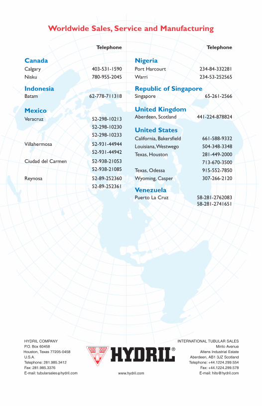
Wedge ThreadTM
Field HandbookFourth Edition
Telephone
CanadaCalgary 403-531-1590
Nisku 780-955-2045
IndonesiaBatam 62-778-711318
MexicoVeracruz 52-298-10213
52-298-10230
52-298-10233
Villahermosa 52-931-44944
52-931-44942
Ciudad del Carmen 52-938-21053
52-938-21085
Reynosa 52-89-252360
52-89-252361
Telephone
NigeriaPort Harcourt 234-84-332281
Warri 234-53-252565
Republic of SingaporeSingapore 65-261-2566
United KingdomAberdeen, Scotland 441-224-878824
United StatesCalifornia, Bakersfield 661-588-9332
Louisiana,Westwego 504-348-3348
Texas, Houston 281-449-2000
713-670-3500
Texas, Odessa 915-552-7850
Wyoming, Casper 307-266-2120
VenezuelaPuerto La Cruz 58-281-2762083
58-281-2741651
Worldwide Sales, Service and Manufacturing
HYDRIL COMPANY INTERNATIONAL TUBULAR SALESP.O. Box 60458 Minto AvenueHouston, Texas 77205-0458 Altens Industrial EstateU.S.A. Aberdeen, AB1 3JZ ScotlandTelephone: 281.985.3412 Telephone: +44.1224.299.554Fax: 281.985.3376 Fax: +44.1224.299.578E-mail: [email protected] E-mail: [email protected]