Embed Size (px)
Citation preview

900 series POWER AMPLIFIERS
P-906MK2P-912MK2P-924MK2
SIGNAL
NORMAL
PROTECTMASTER
ONOFF
PEAK
POWER
SIGNAL
NORMAL
PROTECTMASTER
ONOFF
PEAK
POWER
P-906MK2P-912MK2
P-924MK2
OPERATING INSTRUCTIONS
Thank you for purchasing TOA's 900 Series Power Amplifier. Please carefully follow the instructions in this manual to ensure long, trouble-free use of your equipment.
TABLE OF CONTENTS
1. IMPORTANT SAFETY INSTRUCTIONS ..... 2
2. SAFETY PRECAUTIONS ............................ 3
3. GENERAL DESCRIPTION .......................... 5
4. FEATURES .................................................. 5
5. NOMENCLATURE AND FUNCTIONS Front ............................................................. 6Rear .............................................................. 7
6. INSTALLATION AND CONNECTIONS 6.1. Input Connections ................................. 86.2. Speaker Connections ............................ 9
7. RACK MOUNTING BRACKET ATTACHMENT ... 11
8. OPERATION .............................................. 12
9. VOLUME CONTROL COVER ................... 12
10. DIMENSIONAL DIAGRAMS 10.1. P-906MK2, P-912MK2 ...................... 1310.2. P-924MK2 ......................................... 14
11. SPECIFICATIONS 11.1. P-906MK2, P-912MK2 ...................... 1511.2. P-924MK2 ......................................... 16
2
1. IMPORTANT SAFETY INSTRUCTIONS
• Read these instructions.
• Keep these instructions.
• Heed all warnings.
• Follow all instructions.
• Do not use this apparatus near water.
• Clean only with dry cloth.
• Do not block any ventilation openings. Install in accordance with the manufacturer's instructions.
• Do not install near any heat sources such as radiators, heat registers, stoves, or other apparatus (includingamplifiers) that produce heat.
• Do not defeat the safety purpose of the polarized or grounding-type plug. A polarized plug has two bladeswith one wider than the other. A grounding type plug has two blades and a third grounding prong. The wideblade or the third prong are provided for your safety. If the provided plug does not fit into your outlet, consultan electrician for replacement of the obsolete outlet.
• Protect the power cord from being walked on or pinched particularly at plugs, convenience receptacles, andthe point where they exit from the apparatus.
• Only use attachments/accessories specified by the manufacturer.
• Use only with the cart, stand, tripod, bracket, or table specified by the manufacturer,or sold with the apparatus. When a cart is used, use caution when moving thecart/apparatus combination to avoid injury from tip-over.
• Unplug this apparatus during lightning storms or when unused for long periods of time.
• Refer all servicing to qualified service personnel. Servicing is required when the apparatus has beendamaged in any way, such as power-supply cord or plug is damaged, liquid has been spilled or objects havefallen into the apparatus, the apparatus has been exposed to rain or moisture, does not operate normally, orhas been dropped.
3
2. SAFETY PRECAUTIONS
• Before installation or use, be sure to carefully read all the instructions in this section for correct and safeoperation.
• Be sure to follow all the precautionary instructions in this section, which contain important warnings and/orcautions regarding safety.
• After reading, keep this manual handy for future reference.
Safety Symbol and Message Conventions Safety symbols and messages described below are used in this manual to prevent bodily injury and propertydamage which could result from mishandling. Before operating your product, read this manual first andunderstand the safety symbols and messages so you are thoroughly aware of the potential safety hazards.
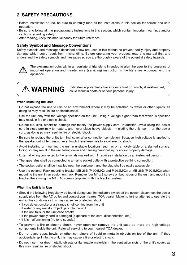
When Installing the Unit
• Do not expose the unit to rain or an environment where it may be splashed by water or other liquids, asdoing so may result in fire or electric shock.
• Use the unit only with the voltage specified on the unit. Using a voltage higher than that which is specifiedmay result in fire or electric shock.
• Do not cut, kink, otherwise damage nor modify the power supply cord. In addition, avoid using the powercord in close proximity to heaters, and never place heavy objects -- including the unit itself -- on the powercord, as doing so may result in fire or electric shock.
• Be sure to replace the unit's terminal cover after connection completion. Because high voltage is applied tothe speaker output terminals, never touch these terminals to avoid electric shock.
• Avoid installing or mounting the unit in unstable locations, such as on a rickety table or a slanted surface.Doing so may result in the unit falling down and causing personal injury and/or property damage.
• External wiring connected to the terminals marked with requires installation by an instructed person.
• The apparatus shall be connected to a mains socket outlet with a protective earthing connection.
• The socket-outlet shall be installed near the equipment and the plug shall be easily accessible.
• Use the optional Rack mounting bracket MB-25B (P-906MK2 and P-912MK2) or MB-35B (P-924MK2) whenmounting the unit in an equipment rack. Remove four M4 x 8 screws on both sides of the unit, and mount thebracket there using the M4 x 16 screws (supplied with the bracket) instead.
When the Unit is in Use
• Should the following irregularity be found during use, immediately switch off the power, disconnect the powersupply plug from the AC outlet and contact your nearest TOA dealer. Make no further attempt to operate theunit in this condition as this may cause fire or electric shock. · If you detect smoke or a strange smell coming from the unit· If water or any metallic object gets into the unit · If the unit falls, or the unit case breaks · If the power supply cord is damaged (exposure of the core, disconnection, etc.)· If it is malfunctioning (no tone sounds.)
• To prevent a fire or electric shock, never open nor remove the unit case as there are high voltagecomponents inside the unit. Refer all servicing to your nearest TOA dealer.
• Do not place cups, bowls, or other containers of liquid or metallic objects on top of the unit. If theyaccidentally spill into the unit, this may cause a fire or electric shock.
• Do not insert nor drop metallic objects or flammable materials in the ventilation slots of the unit's cover, asthis may result in fire or electric shock.
Indicates a potentially hazardous situation which, if mishandled,could result in death or serious personal injury. WARNING
The exclamation point within an equilateral triangle is intended to alert the user to the presence ofimportant operation and maintenance (servicing) instruction in the literature accompanying theappliance.
4
When Installing the Unit
• Never plug in nor remove the power supply plug with wet hands, as doing so may cause electric shock.
• When unplugging the power supply cord, be sure to grasp the power supply plug; never pull on the corditself. Operating the unit with a damaged power supply cord may cause a fire or electric shock.
• When moving the unit, be sure to remove its power supply cord from the wall outlet. Moving the unit with thepower cord connected to the outlet may cause damage to the power cord, resulting in fire or electric shock.When removing the power cord, be sure to hold its plug to pull.
• Do not block the ventilation slots in the unit's cover. Doing so may cause heat to build up inside the unit andresult in fire.
• Avoid installing the unit in humid or dusty locations, in locations exposed to the direct sunlight, near theheaters, or in locations generating sooty smoke or steam as doing otherwise may result in fire or electricshock.
• To avoid electric shocks, be sure to unplug the unit's power supply cord when connecting speakers.
• Be sure to follow the instructions below when rack-mounting the unit. Failure to do so may cause a fire orpersonal injury.· Install the equipment rack on a stable, hard floor. Fix it with anchor bolts or take other arrangements to
prevent it from falling down.· When connecting the unit's power cord to an AC outlet, use the AC outlet with current capacity allowable to
the unit.· No rack-mounting screws are supplied with the unit. Separately prepare the appropriate screws for the
rack.
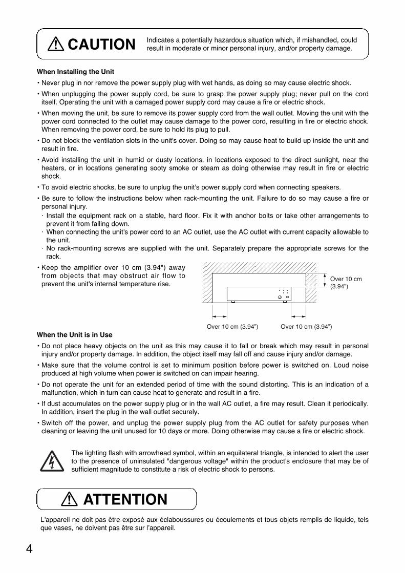
• Keep the amplifier over 10 cm (3.94") awayfrom objects that may obstruct air flow toprevent the unit's internal temperature rise.
When the Unit is in Use
• Do not place heavy objects on the unit as this may cause it to fall or break which may result in personalinjury and/or property damage. In addition, the object itself may fall off and cause injury and/or damage.
• Make sure that the volume control is set to minimum position before power is switched on. Loud noiseproduced at high volume when power is switched on can impair hearing.
• Do not operate the unit for an extended period of time with the sound distorting. This is an indication of amalfunction, which in turn can cause heat to generate and result in a fire.
• If dust accumulates on the power supply plug or in the wall AC outlet, a fire may result. Clean it periodically.In addition, insert the plug in the wall outlet securely.
• Switch off the power, and unplug the power supply plug from the AC outlet for safety purposes whencleaning or leaving the unit unused for 10 days or more. Doing otherwise may cause a fire or electric shock.
Indicates a potentially hazardous situation which, if mishandled, couldresult in moderate or minor personal injury, and/or property damage.CAUTION
L'appareil ne doit pas être exposé aux éclaboussures ou écoulements et tous objets remplis de liquide, telsque vases, ne doivent pas être sur l’appareil.
ATTENTION
The lighting flash with arrowhead symbol, within an equilateral triangle, is intended to alert the userto the presence of uninsulated "dangerous voltage" within the product's enclosure that may be ofsufficient magnitude to constitute a risk of electric shock to persons.
Over 10 cm (3.94”) Over 10 cm (3.94”)
Over 10 cm(3.94”)
5
3. GENERAL DESCRIPTION
TOA's P-906MK2 (rated output: 60 W), P-912MK2 (120 W), and P-924MK2 (240 W) Power Amplifiers featurea high-impedance direct input terminal and an input port that permits the use of various optional plug-inmodules. The most appropriate plug-in module can be selected depending on applications.The power amplifiers have a low-cut switch for a cutoff frequency of 60 Hz, and an input level switch for inputsensitivity of 0 dBV (1 V) or –20 dBV (100 mV). The speaker output terminals are designed to match 25 V or70 V line and 4 Ω or 8 Ω speaker systems.Each Power Amplifier can be mounted in an EIA equipment rack with the addition of the optional rackmounting bracket MB-25B (P-906MK2 and P-912MK2) or MB-35B (P-924MK2). The optional perforated panelPF-511 provides suitable ventilation, finished in black color to match the Power Amplifiers.
4. FEATURES
• A wide frequency response of 20 to 20,000 Hz (±1 dB)
• Low distortion and low noise level
• Usable a wide range of plug-in optional modules
• Built-in protection circuitry
• Input level switch (selectable 0 dBV or –20 dBV)
• Mountable in a standard 19" equipment rack (rack mounting bracket: optional)
6
900 SERIES AMPLIFIER P – 924MK2
SIGNAL NORMAL
PROTECT
MASTER
ONOFF
PEAK
POWER
900 SERIES AMPLIFIER P – 906MK2
SIGNAL NORMAL
PROTECT
MASTER
ONOFF
PEAK
POWER
3 4 5 6 7
2
1
3 4 5 6 7
2
1
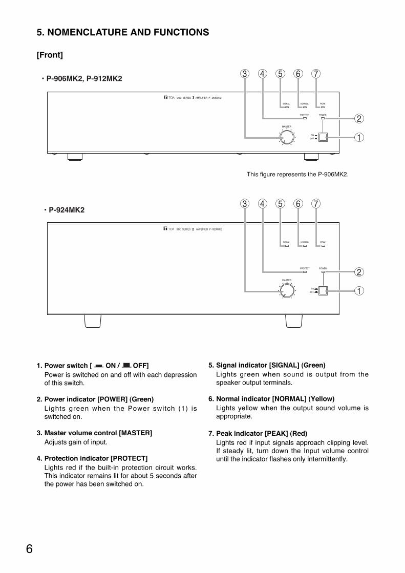
• P-906MK2, P-912MK2
This figure represents the P-906MK2.
• P-924MK2
5. NOMENCLATURE AND FUNCTIONS
[Front]
1. Power switch [ ON / OFF]Power is switched on and off with each depressionof this switch.
2. Power indicator [POWER] (Green)Lights green when the Power switch (1) isswitched on.
3. Master volume control [MASTER]Adjusts gain of input.
4. Protection indicator [PROTECT] Lights red if the built-in protection circuit works.This indicator remains lit for about 5 seconds afterthe power has been switched on.
5. Signal indicator [SIGNAL] (Green)Lights green when sound is output from thespeaker output terminals.
6. Normal indicator [NORMAL] (Yellow)Lights yellow when the output sound volume isappropriate.
7. Peak indicator [PEAK] (Red)Lights red if input signals approach clipping level.If steady lit, turn down the Input volume controluntil the indicator flashes only intermittently.
7
HOT
ONLOWCUT
INPUTLEVEL
OFF
0dB– 20dB
COM
INPUTDIRECT
4Ω 8Ω
70V
25V
COM
CLASS 2 WIRINGMAY BE USED.
INPUT
ON
OFF
0dBV
HOT
COM
–20dBV
LOW CUT
INPUT LEVEL
70V
25V
8Ω
COM
OT IN
4Ω
8 9 10 11 12
13 14 15
14 15
8 9 10 1112
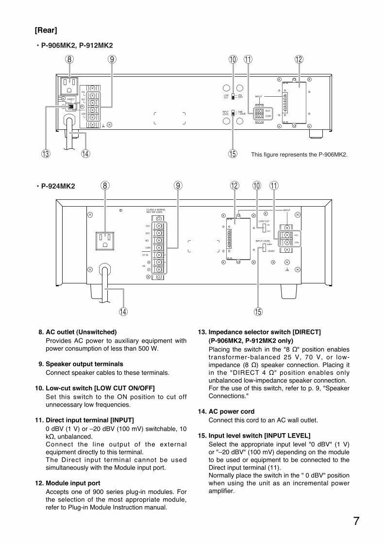
• P-906MK2, P-912MK2
This figure represents the P-906MK2.
• P-924MK2
[Rear]
8. AC outlet (Unswitched)Provides AC power to auxiliary equipment withpower consumption of less than 500 W.
9. Speaker output terminalsConnect speaker cables to these terminals.
10. Low-cut switch [LOW CUT ON/OFF]Set this switch to the ON position to cut offunnecessary low frequencies.
11. Direct input terminal [INPUT]0 dBV (1 V) or –20 dBV (100 mV) switchable, 10kΩ, unbalanced.Connect the l ine output of the externalequipment directly to this terminal.The Direct input terminal cannot be usedsimultaneously with the Module input port.
12. Module input port Accepts one of 900 series plug-in modules. Forthe selection of the most appropriate module,refer to Plug-in Module Instruction manual.
13. Impedance selector switch [DIRECT](P-906MK2, P-912MK2 only)Placing the switch in the "8 Ω" position enablestransformer-balanced 25 V, 70 V, or low-impedance (8 Ω) speaker connection. Placing itin the "DIRECT 4 Ω" position enables onlyunbalanced low-impedance speaker connection.For the use of this switch, refer to p. 9, "SpeakerConnections."
14. AC power cordConnect this cord to an AC wall outlet.
15. Input level switch [INPUT LEVEL]Select the appropriate input level "0 dBV" (1 V)or "–20 dBV" (100 mV) depending on the moduleto be used or equipment to be connected to theDirect input terminal (11). Normally place the switch in the " 0 dBV" positionwhen using the unit as an incremental poweramplifier.
8
6. INSTALLATION AND CONNECTIONS
6.1. Input Connections
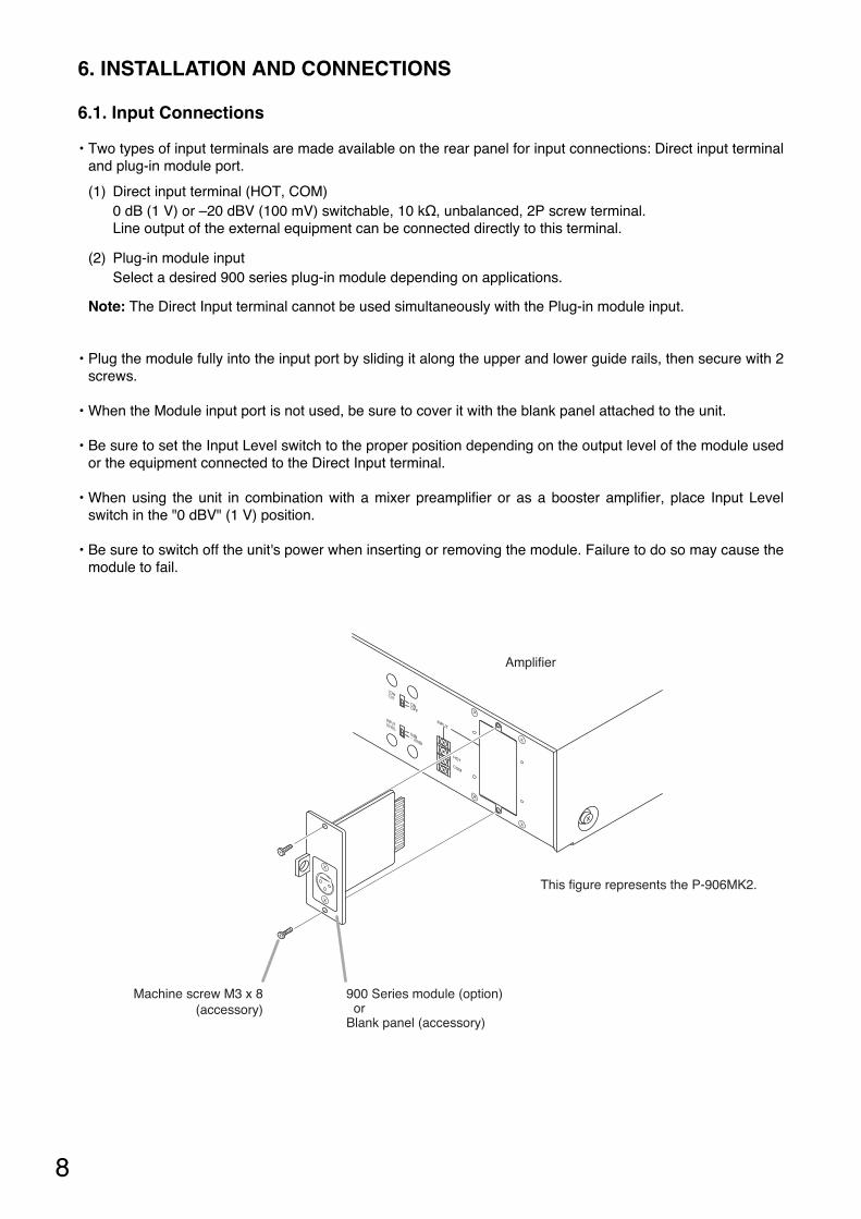
• Two types of input terminals are made available on the rear panel for input connections: Direct input terminaland plug-in module port.
(1) Direct input terminal (HOT, COM)0 dB (1 V) or –20 dBV (100 mV) switchable, 10 kΩ, unbalanced, 2P screw terminal.Line output of the external equipment can be connected directly to this terminal.
(2) Plug-in module inputSelect a desired 900 series plug-in module depending on applications.
Note: The Direct Input terminal cannot be used simultaneously with the Plug-in module input.
• Plug the module fully into the input port by sliding it along the upper and lower guide rails, then secure with 2screws.
• When the Module input port is not used, be sure to cover it with the blank panel attached to the unit.
• Be sure to set the Input Level switch to the proper position depending on the output level of the module usedor the equipment connected to the Direct Input terminal.
• When using the unit in combination with a mixer preamplifier or as a booster amplifier, place Input Levelswitch in the "0 dBV" (1 V) position.
• Be sure to switch off the unit's power when inserting or removing the module. Failure to do so may cause themodule to fail.
HOT
ON
LOWCUT
INPUTLEVEL
OFF
0dB– 20dB
COM
INPUT
Amplifier
900 Series module (option) orBlank panel (accessory)
Machine screw M3 x 8(accessory)
This figure represents the P-906MK2.
9
70V
25V
8Ω
COM
OT IN
4Ω
DIRECT4Ω 8Ω
70V
25V
COM
• P-906MK2, P-912MK2
• P-924MK2
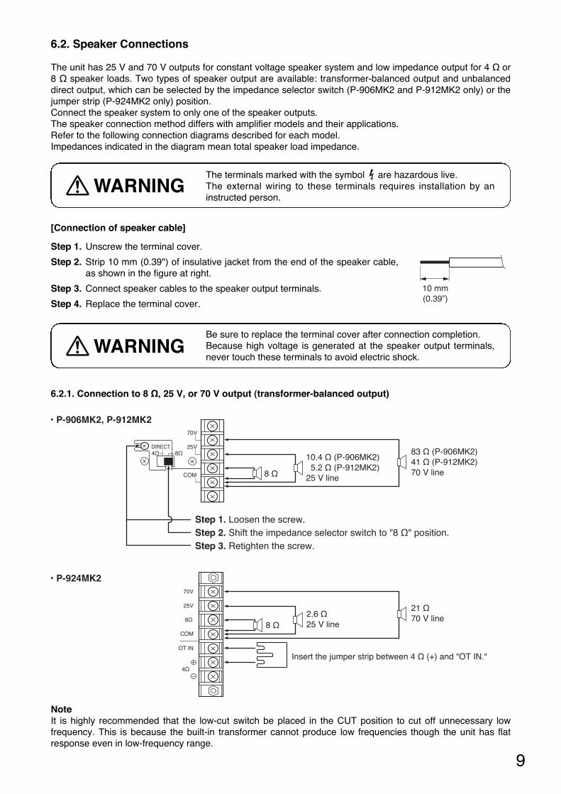
8 Ω
10.4 Ω (P-906MK2) 5.2 Ω (P-912MK2)25 V line
83 Ω (P-906MK2)41 Ω (P-912MK2)70 V line
Step 1. Loosen the screw.Step 2. Shift the impedance selector switch to "8 Ω" position.Step 3. Retighten the screw.
8 Ω
Insert the jumper strip between 4 Ω (+) and "OT IN."
2.6 Ω25 V line
21 Ω70 V line
6.2. Speaker Connections
The unit has 25 V and 70 V outputs for constant voltage speaker system and low impedance output for 4 Ω or8 Ω speaker loads. Two types of speaker output are available: transformer-balanced output and unbalanceddirect output, which can be selected by the impedance selector switch (P-906MK2 and P-912MK2 only) or thejumper strip (P-924MK2 only) position.Connect the speaker system to only one of the speaker outputs. The speaker connection method differs with amplifier models and their applications.Refer to the following connection diagrams described for each model.Impedances indicated in the diagram mean total speaker load impedance.
6.2.1. Connection to 8 Ω, 25 V, or 70 V output (transformer-balanced output)
Step 1. Unscrew the terminal cover.
Step 2. Strip 10 mm (0.39") of insulative jacket from the end of the speaker cable,as shown in the figure at right.
Step 3. Connect speaker cables to the speaker output terminals.
Step 4. Replace the terminal cover.
10 mm(0.39”)
[Connection of speaker cable]
NoteIt is highly recommended that the low-cut switch be placed in the CUT position to cut off unnecessary lowfrequency. This is because the built-in transformer cannot produce low frequencies though the unit has flatresponse even in low-frequency range.
Be sure to replace the terminal cover after connection completion.Because high voltage is generated at the speaker output terminals,never touch these terminals to avoid electric shock.
WARNING
The terminals marked with the symbol are hazardous live. The external wiring to these terminals requires installation by aninstructed person.
WARNING
10
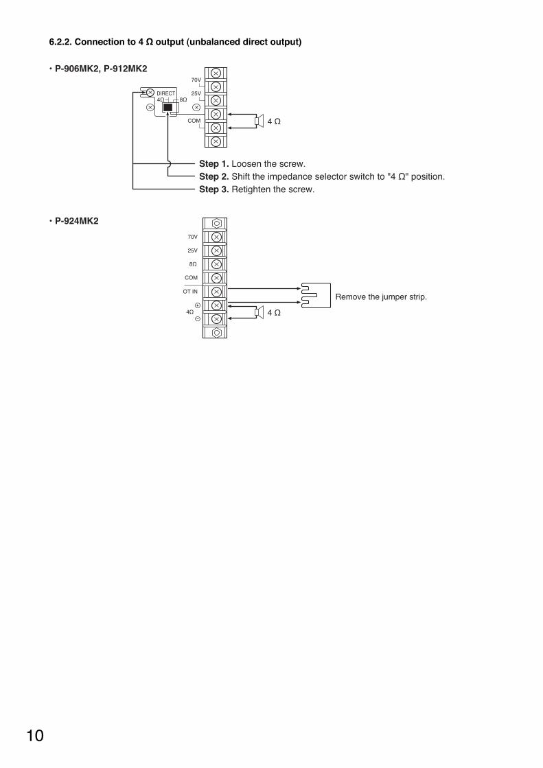
6.2.2. Connection to 4 Ω output (unbalanced direct output)
DIRECT4Ω 8Ω
70V
25V
COM
70V
25V
8Ω
COM
OT IN
4Ω
• P-906MK2, P-912MK2
• P-924MK2
4 Ω
4 Ω
Step 1. Loosen the screw.Step 2. Shift the impedance selector switch to "4 Ω" position.Step 3. Retighten the screw.
Remove the jumper strip.
11
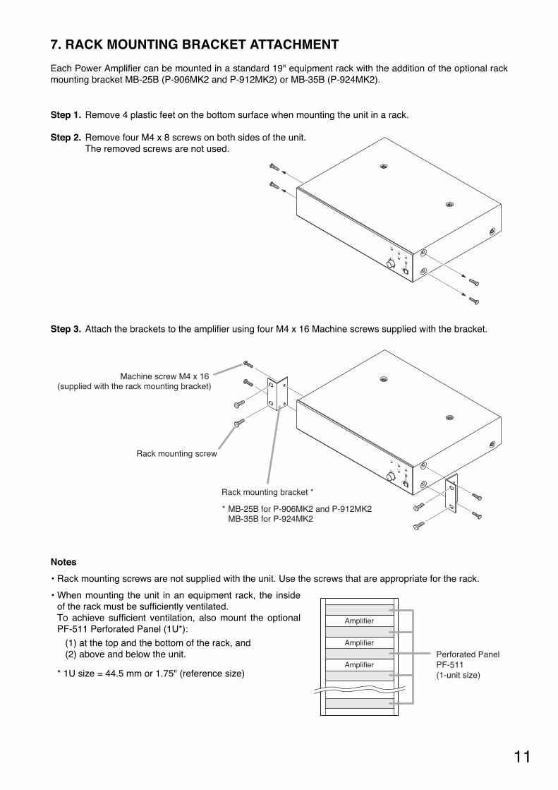
7. RACK MOUNTING BRACKET ATTACHMENT
Each Power Amplifier can be mounted in a standard 19" equipment rack with the addition of the optional rackmounting bracket MB-25B (P-906MK2 and P-912MK2) or MB-35B (P-924MK2).
Notes
• Rack mounting screws are not supplied with the unit. Use the screws that are appropriate for the rack.
• When mounting the unit in an equipment rack, the insideof the rack must be sufficiently ventilated. To achieve sufficient ventilation, also mount the optionalPF-511 Perforated Panel (1U*):
(1) at the top and the bottom of the rack, and(2) above and below the unit.
* 1U size = 44.5 mm or 1.75" (reference size)
Amplifier
Amplifier
AmplifierPerforated PanelPF-511 (1-unit size)
SIGNAL
NORMAL
PROTECTMASTER
ONOFF
PEAK
POWER
SIGNAL
NORMAL
PROTECTMASTER
ONOFF
PEAK
POWER
Rack mounting screw
Machine screw M4 x 16 (supplied with the rack mounting bracket)
Rack mounting bracket *
* MB-25B for P-906MK2 and P-912MK2MB-35B for P-924MK2
Step 1. Remove 4 plastic feet on the bottom surface when mounting the unit in a rack.
Step 2. Remove four M4 x 8 screws on both sides of the unit. The removed screws are not used.
Step 3. Attach the brackets to the amplifier using four M4 x 16 Machine screws supplied with the bracket.
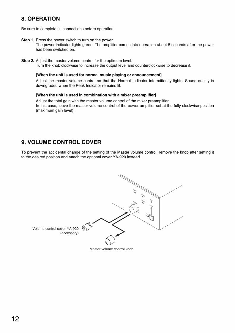
Master volume control knob
Volume control cover YA-920(accessory)
9. VOLUME CONTROL COVER
To prevent the accidental change of the setting of the Master volume control, remove the knob after setting itto the desired position and attach the optional cover YA-920 instead.
12
8. OPERATION
Be sure to complete all connections before operation.
Step 1. Press the power switch to turn on the power.The power indicator lights green. The amplifier comes into operation about 5 seconds after the powerhas been switched on.
Step 2. Adjust the master volume control for the optimum level. Turn the knob clockwise to increase the output level and counterclockwise to decrease it.
[When the unit is used for normal music playing or announcement]Adjust the master volume control so that the Normal Indicator intermittently lights. Sound quality isdowngraded when the Peak Indicator remains lit.
[When the unit is used in combination with a mixer preamplifier]Adjust the total gain with the master volume control of the mixer preamplifier.In this case, leave the master volume control of the power amplifier set at the fully clockwise position(maximum gain level).
13
10. DIMENSIONAL DIAGRAMS
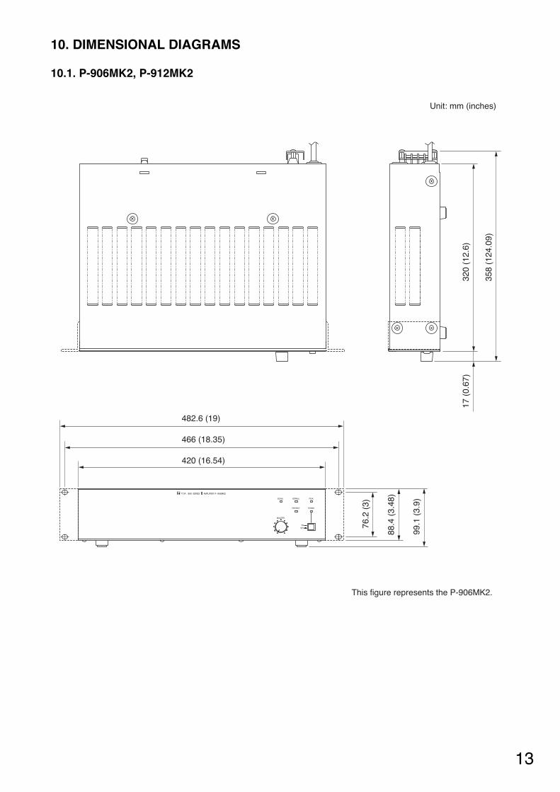
10.1. P-906MK2, P-912MK2
900 SERIES AMPLIFIER P – 906MK2
SIGNAL NORMAL
PROTECT
MASTER
ONOFF
PEAK
POWER
320
(12.
6)17
(0.
67)
358
(124
.09)
Unit: mm (inches)
76.2
(3)
88.4
(3.
48)
99.1
(3.
9)
466 (18.35)
420 (16.54)
This figure represents the P-906MK2.
482.6 (19)
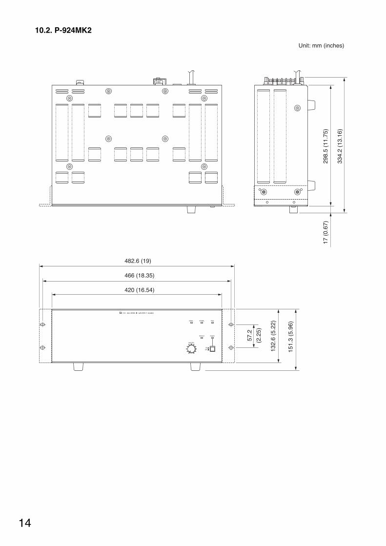
10.2. P-924MK2
900 SERIES AMPLIFIER P – 924MK2
SIGNAL NORMAL
PROTECT
MASTER
ONOFF
PEAK
POWER
Unit: mm (inches)
298.
5 (1
1.75
)17
(0.
67)
334.
2 (1
3.16
)
482.6 (19)
466 (18.35)
420 (16.54)
57.2
(2.2
5)
132.
6 (5
.22)
151.
3 (5
.96)
14
15
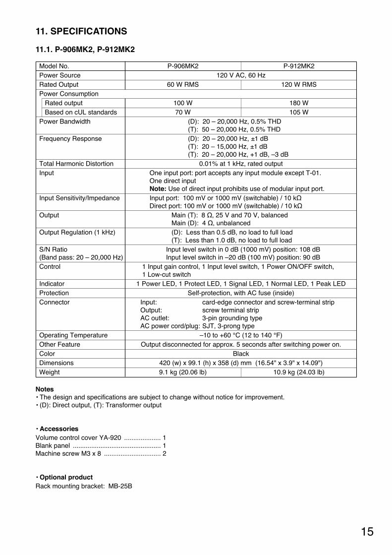
P-906MK2 P-912MK2120 V AC, 60 Hz
60 W RMS 120 W RMS
100 W 180 W70 W 105 W
(D): 20 – 20,000 Hz, 0.5% THD(T): 50 – 20,000 Hz, 0.5% THD(D): 20 – 20,000 Hz, ±1 dB(T): 20 – 15,000 Hz, ±1 dB (T): 20 – 20,000 Hz, +1 dB, –3 dB
0.01% at 1 kHz, rated outputOne input port: port accepts any input module except T-01.One direct input Note: Use of direct input prohibits use of modular input port.Input port: 100 mV or 1000 mV (switchable) / 10 kΩDirect port: 100 mV or 1000 mV (switchable) / 10 kΩ
Main (T): 8 Ω, 25 V and 70 V, balancedMain (D): 4 Ω, unbalanced(D): Less than 0.5 dB, no load to full load (T): Less than 1.0 dB, no load to full load
Input level switch in 0 dB (1000 mV) position: 108 dBInput level switch in –20 dB (100 mV) position: 90 dB
1 Input gain control, 1 Input level switch, 1 Power ON/OFF switch, 1 Low-cut switch
1 Power LED, 1 Protect LED, 1 Signal LED, 1 Normal LED, 1 Peak LEDSelf-protection, with AC fuse (inside)
Input: card-edge connector and screw-terminal stripOutput: screw terminal stripAC outlet: 3-pin grounding typeAC power cord/plug: SJT, 3-prong type
–10 to +60 °C (12 to 140 °F)Output disconnected for approx. 5 seconds after switching power on.
Black420 (w) x 99.1 (h) x 358 (d) mm (16.54" x 3.9" x 14.09") 9.1 kg (20.06 lb) 10.9 kg (24.03 lb)
Model No.Power SourceRated OutputPower Consumption
Rated outputBased on cUL standards
Power Bandwidth
Frequency Response
Total Harmonic DistortionInput
Input Sensitivity/Impedance
Output
Output Regulation (1 kHz)
S/N Ratio(Band pass: 20 – 20,000 Hz)Control
IndicatorProtectionConnector
Operating TemperatureOther FeatureColorDimensionsWeight
11. SPECIFICATIONS
Notes• The design and specifications are subject to change without notice for improvement. • (D): Direct output, (T): Transformer output
• AccessoriesVolume control cover YA-920 .................... 1Blank panel ................................................ 1Machine screw M3 x 8 ............................... 2
• Optional productRack mounting bracket: MB-25B
11.1. P-906MK2, P-912MK2
133-12-116-6C
URL: http://www.toa.jp/
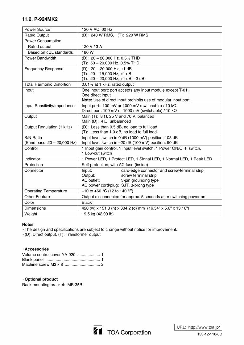
120 V AC, 60 Hz(D): 240 W RMS, (T): 220 W RMS
120 V / 3 A180 W(D): 20 – 20,000 Hz, 0.5% THD(T): 50 – 20,000 Hz, 0.5% THD(D): 20 – 20,000 Hz, ±1 dB(T): 20 – 15,000 Hz, ±1 dB (T): 20 – 20,000 Hz, +1 dB, –3 dB0.01% at 1 kHz, rated outputOne input port: port accepts any input module except T-01.One direct input Note: Use of direct input prohibits use of modular input port.Input port: 100 mV or 1000 mV (switchable) / 10 kΩDirect port: 100 mV or 1000 mV (switchable) / 10 kΩMain (T): 8 Ω, 25 V and 70 V, balancedMain (D): 4 Ω, unbalanced(D): Less than 0.5 dB, no load to full load (T): Less than 1.0 dB, no load to full loadInput level switch in 0 dB (1000 mV) position: 108 dBInput level switch in –20 dB (100 mV) position: 90 dB1 Input gain control, 1 Input level switch, 1 Power ON/OFF switch, 1 Low-cut switch1 Power LED, 1 Protect LED, 1 Signal LED, 1 Normal LED, 1 Peak LEDSelf-protection, with AC fuse (inside)Input: card-edge connector and screw-terminal stripOutput: screw terminal stripAC outlet: 3-pin grounding typeAC power cord/plug: SJT, 3-prong type–10 to +60 °C (12 to 140 °F)Output disconnected for approx. 5 seconds after switching power on.Black420 (w) x 151.3 (h) x 334.2 (d) mm (16.54" x 5.6" x 13.16") 19.5 kg (42.99 lb)
Power SourceRated OutputPower Consumption
Rated outputBased on cUL standards
Power Bandwidth
Frequency Response
Total Harmonic DistortionInput
Input Sensitivity/Impedance
Output
Output Regulation (1 kHz)
S/N Ratio(Band pass: 20 – 20,000 Hz)Control
IndicatorProtectionConnector
Operating TemperatureOther FeatureColorDimensionsWeight
Notes• The design and specifications are subject to change without notice for improvement. • (D): Direct output, (T): Transformer output
• AccessoriesVolume control cover YA-920 .................... 1Blank panel ................................................ 1Machine screw M3 x 8 ............................... 2
• Optional product Rack mounting bracket: MB-35B
11.2. P-924MK2